EP3650743B1 - Dispositif de fixation - Google Patents
Dispositif de fixation Download PDFInfo
- Publication number
- EP3650743B1 EP3650743B1 EP19201618.6A EP19201618A EP3650743B1 EP 3650743 B1 EP3650743 B1 EP 3650743B1 EP 19201618 A EP19201618 A EP 19201618A EP 3650743 B1 EP3650743 B1 EP 3650743B1
- Authority
- EP
- European Patent Office
- Prior art keywords
- suspension structure
- fastening device
- opening
- supporting position
- luminaire
- Prior art date
- Legal status (The legal status is an assumption and is not a legal conclusion. Google has not performed a legal analysis and makes no representation as to the accuracy of the status listed.)
- Active
Links
Images

Classifications
-
- F—MECHANICAL ENGINEERING; LIGHTING; HEATING; WEAPONS; BLASTING
- F16—ENGINEERING ELEMENTS AND UNITS; GENERAL MEASURES FOR PRODUCING AND MAINTAINING EFFECTIVE FUNCTIONING OF MACHINES OR INSTALLATIONS; THERMAL INSULATION IN GENERAL
- F16G—BELTS, CABLES, OR ROPES, PREDOMINANTLY USED FOR DRIVING PURPOSES; CHAINS; FITTINGS PREDOMINANTLY USED THEREFOR
- F16G11/00—Means for fastening cables or ropes to one another or to other objects; Caps or sleeves for fixing on cables or ropes
- F16G11/10—Quick-acting fastenings; Clamps holding in one direction only
-
- F—MECHANICAL ENGINEERING; LIGHTING; HEATING; WEAPONS; BLASTING
- F16—ENGINEERING ELEMENTS AND UNITS; GENERAL MEASURES FOR PRODUCING AND MAINTAINING EFFECTIVE FUNCTIONING OF MACHINES OR INSTALLATIONS; THERMAL INSULATION IN GENERAL
- F16G—BELTS, CABLES, OR ROPES, PREDOMINANTLY USED FOR DRIVING PURPOSES; CHAINS; FITTINGS PREDOMINANTLY USED THEREFOR
- F16G11/00—Means for fastening cables or ropes to one another or to other objects; Caps or sleeves for fixing on cables or ropes
- F16G11/10—Quick-acting fastenings; Clamps holding in one direction only
- F16G11/103—Quick-acting fastenings; Clamps holding in one direction only deforming the cable by bending it around or inserting it into the fastener
-
- F—MECHANICAL ENGINEERING; LIGHTING; HEATING; WEAPONS; BLASTING
- F16—ENGINEERING ELEMENTS AND UNITS; GENERAL MEASURES FOR PRODUCING AND MAINTAINING EFFECTIVE FUNCTIONING OF MACHINES OR INSTALLATIONS; THERMAL INSULATION IN GENERAL
- F16M—FRAMES, CASINGS OR BEDS OF ENGINES, MACHINES OR APPARATUS, NOT SPECIFIC TO ENGINES, MACHINES OR APPARATUS PROVIDED FOR ELSEWHERE; STANDS; SUPPORTS
- F16M13/00—Other supports for positioning apparatus or articles; Means for steadying hand-held apparatus or articles
- F16M13/02—Other supports for positioning apparatus or articles; Means for steadying hand-held apparatus or articles for supporting on, or attaching to, an object, e.g. tree, gate, window-frame, cycle
- F16M13/027—Ceiling supports
-
- F—MECHANICAL ENGINEERING; LIGHTING; HEATING; WEAPONS; BLASTING
- F21—LIGHTING
- F21S—NON-PORTABLE LIGHTING DEVICES; SYSTEMS THEREOF; VEHICLE LIGHTING DEVICES SPECIALLY ADAPTED FOR VEHICLE EXTERIORS
- F21S8/00—Lighting devices intended for fixed installation
- F21S8/04—Lighting devices intended for fixed installation intended only for mounting on a ceiling or the like overhead structures
- F21S8/06—Lighting devices intended for fixed installation intended only for mounting on a ceiling or the like overhead structures by suspension
- F21S8/061—Lighting devices intended for fixed installation intended only for mounting on a ceiling or the like overhead structures by suspension with a non-rigid pendant, i.e. a cable, wire or chain
-
- F—MECHANICAL ENGINEERING; LIGHTING; HEATING; WEAPONS; BLASTING
- F21—LIGHTING
- F21V—FUNCTIONAL FEATURES OR DETAILS OF LIGHTING DEVICES OR SYSTEMS THEREOF; STRUCTURAL COMBINATIONS OF LIGHTING DEVICES WITH OTHER ARTICLES, NOT OTHERWISE PROVIDED FOR
- F21V21/00—Supporting, suspending, or attaching arrangements for lighting devices; Hand grips
- F21V21/10—Pendants, arms, or standards; Fixing lighting devices to pendants, arms, or standards
- F21V21/112—Fixing lighting devices to pendants
-
- F—MECHANICAL ENGINEERING; LIGHTING; HEATING; WEAPONS; BLASTING
- F16—ENGINEERING ELEMENTS AND UNITS; GENERAL MEASURES FOR PRODUCING AND MAINTAINING EFFECTIVE FUNCTIONING OF MACHINES OR INSTALLATIONS; THERMAL INSULATION IN GENERAL
- F16B—DEVICES FOR FASTENING OR SECURING CONSTRUCTIONAL ELEMENTS OR MACHINE PARTS TOGETHER, e.g. NAILS, BOLTS, CIRCLIPS, CLAMPS, CLIPS OR WEDGES; JOINTS OR JOINTING
- F16B21/00—Means for preventing relative axial movement of a pin, spigot, shaft or the like and a member surrounding it; Stud-and-socket releasable fastenings
- F16B21/09—Releasable fastening devices with a stud engaging a keyhole slot
Definitions
- the present invention relates to a fastening device for fastening a luminaire such as a pendant luminaire to a suspension structure, a luminaire housing comprising such a fastening device, a luminaire comprising such a luminaire housing and a luminaire system comprising such a luminaire.
- Fastening devices of the type mentioned above are generally known from the prior art.
- luminaires which have a fastening device formed with the luminaire body or luminaire housing, which fastens the luminaire to a suspension structure, such as a cable suspension.
- the suspension structure typically has a suspension element, in particular a cable, and a suspension body, for example in the form of a nipple or a ball, connected to the distal end of the suspension element.
- the suspension structure can be fixedly mounted to the fastening device, for example with a screw.
- the suspension structure can also be mounted to the fastening device via a corresponding receptacle by inserting the suspension structure into the fastening device and moving it to a supporting position in which the suspension structure supports the fastening device in a suspended manner or in which the suspension body is blocked in the direction of the supporting force.
- This is done, for example, in the simplest form by means of a horizontal slot into which the suspension structure or the cable suspension is inserted laterally, so that the suspension structure is suspended accordingly, in particular via the suspension body.
- Another embodiment known from the prior art has a type of keyhole opening, which has an opening with a larger diameter and a further opening with a smaller diameter connected to this directly or via a longitudinal slot.
- the larger opening has a diameter that is larger than the suspension body.
- the further or smaller opening has a diameter that is correspondingly smaller than the suspension body.
- the longitudinal slot if present, is preferably narrower than the two openings, but wide enough that, for example, the cable of the cable suspension fits through it.
- the suspension structure is then inserted with the suspension body first into the larger opening and moved towards the smaller opening, where the suspension structure rests against the suspension body and is thus held.
- the securing of the suspension structure or the suspension body known from the state of the art is safe, but requires a high level of assembly effort, since in addition to threading the suspension structure, another component is required to block the inserted suspension structure.
- the invention relates to a luminaire housing comprising a fastening device for fastening a luminaire, such as a pendant luminaire (or another element), to a suspension structure, with at least one fastening structure, wherein the at least one fastening structure comprises: an opening and a slot connected to the opening, which are designed such that a suspension structure inserted into the fastening device via the opening can be moved via the slot into a supporting position in which the suspension structure supports the fastening device in a suspended manner.
- the slot has a serrated section for preventing movement of the suspension structure from the supporting position, and the slot is designed such that the suspension structure can be (automatically) driven into the supporting position by the weight of the fastening device.
- preventing a movement of the suspension structure from the carrying position is understood to mean that a manual movement of the suspension structure from the carrying position (for example by a fitter) is still possible, but an (unintentional) movement of the suspension structure from the carrying position, in particular due to external forces or impacts acting on the fastening device, is prevented.
- the slot can also be provided with only the jagged or deliberately non-rectilinear section, or the slot can be designed such that the suspension structure can be driven into the supporting position by the weight of the fastening device.
- the serrated section has a first and second subsection forming the serrated section, wherein the first and second subsections extend in such a way that, when the suspension structure supports the fastening device in the supporting position, movement of the suspension structure from the first subsection into the second subsection and thus out of the supporting position is prevented.
- the angle between the first subsection and the second subsection ensures that the suspension structure cannot be inadvertently moved out of the supporting position.
- the angle lies in a range of 20° to 70°, preferably in a range of 30° to 50°, for example, is substantially 37°.
- the first subsection is longer than the second subsection. Consequently, the first subsection can advantageously ensure that external forces or impacts acting on the fastening structure and thus a skidding suspension structure are absorbed.
- the slot has at least one further serrated section, wherein the further serrated section Section is connected (directly) to the opening and (directly) to the serrated section, so that the suspension structure inserted into the fastening device via the opening can be moved into the supporting position via the further serrated section and the serrated section, and the serrated sections can prevent movement of the suspension structure from the supporting position.
- the suspension structure can be held even more securely in the supporting position, since the further serrated section, together with the serrated section, provides a type of labyrinth, lightning, or zigzag guide, which even better prevents unintentional movement of the suspension structure from the supporting position.
- the further serrated section can have a (further) first and (further) second subsection forming the (further) serrated section, wherein the (further) first subsection is (directly) connected to the opening and the (further) second subsection is (directly) connected to the serrated section.
- the (further) second subsection of the further serrated section is the second subsection of the serrated section.
- the (further) first and the (further) second subsections can extend in such a way that, when the suspension structure supports the fastening device in the carrying position, a movement of the suspension structure from the (further) second subsection into the (further) first subsection and thus out of the carrying position can be prevented.
- the angle between the (further) first subsection and the (further) second subsection in particular causes the suspension structure to move into the (further) first subsection and thus out of the carrying position.
- This angle is preferably acute and is particularly preferably in a range of 70° to 90°. For example, the angle is substantially 80°.
- the slot preferably extends such that a contact area, with which the suspension structure is in contact in the carrying position in order to support the fastening device, is arranged higher than the opening (on the side of the contact area) when the suspension structure supports the fastening device in the carrying position.
- the weight of the fastening device thus causes the suspension structure - due to the movement of the fastening device by its weight in the direction of the weight force - to cover the height difference between the opening and the contact area relative to the fastening device in order to reach the carrying position.
- the weight of the fastening device thus holds the suspension structure in the carrying position.
- the slot runs obliquely to the horizontal when the suspension structure supports the fastening device in the carrying position, so that the suspension structure can be driven into the carrying position by the weight of the fastening device.
- securing the suspension structure in the carrying position by the weight of the fastening device can be provided particularly easily.
- the slot runs at an angle of 5° to 15°, particularly preferably at an angle of 10°, to the horizontal when the suspension structure supports the fastening device in the carrying position.
- the slot is formed in an inclined (sloped) surface of the mounting structure so as to extend obliquely to the horizontal when the suspension structure supports the mounting device in the supporting position. Since an inclined surface is easy to provide, securing the suspension structure in the supporting position by the weight of the mounting device can be particularly easily achieved.
- the at least one fastening structure can have a further opening that is (directly) connected to the slot, in particular to the first subsection of the serrated section, and is designed to hold the suspension structure in the supporting position.
- the geometry of the further opening thus ensures, in particular, that the suspension structure is held or (partially) received in the supporting position in a defined manner, namely in the region of the opening. It is preferred if the further opening has the aforementioned contact area.
- the opening and/or the further opening can be designed to correspond to the suspension structure and/or to be round, preferably circular, or polygonal, preferably rectangular or square.
- the advantageous purpose is thus that the suspension structure can be easily inserted through the opening into the fastening device or can be held in a defined manner and preferably blocked by the further opening.
- the fact that the opening is designed to correspond to the suspension structure advantageously ensures that the suspension structure or its suspension body fits into the opening in only one orientation, for example vertically, whereby the installation of the suspension structure in the fastening device is simplified and more secure.
- the opening is preferably larger than the further opening so that the suspension structure can be passed through the opening and cannot be passed through the further opening.
- the opening preferably has a diameter of 5 mm to 10 mm, particularly preferably 8.5 mm.
- the further opening preferably has a diameter of 2 mm to 6 mm, particularly preferably 4.5 mm.
- the fastening device can have at least two, preferably three or four fastening structures. This is particularly advantageous when heavier and/or larger objects or devices, such as a large-area luminaire, in particular a pendant luminaire, are to be fastened to a corresponding number of suspension structures via the fastening device.
- the plurality of fastening structures are preferably distributed (arranged) evenly over the fastening device so that, in particular, the weight of the fastening device and, if present, the weight of the luminaire connected to it can be distributed evenly across the corresponding number of suspension structures.
- the plurality of fastening structures are formed in regions delimiting the fastening device, such as corner regions. This is particularly advantageous for good accessibility of the fastening structures.
- the fastening device is preferably made of aluminum, in particular by an aluminum die-casting process. This allows for a lightweight fastening device while simultaneously maintaining sufficient strength.
- the at least one fastening structure can be formed integrally with the fastening device.
- the invention relates to a luminaire housing comprising a fastening device as described above.
- the fastening device is preferably formed integrally with the luminaire housing; the luminaire housing and fastening device are preferably manufactured together using an aluminum die-casting process.
- the fastening device is detachably connected to the luminaire housing is provided, for example via a clip connection.
- the invention relates to a luminaire, in particular a pendant luminaire, comprising a luminaire housing as described above and at least one illuminant, such as an LED, accommodated in the luminaire housing.
- the invention relates to a lighting system comprising a luminaire as described above and a suspension structure (for example in the form of a cable suspension with a suspension body provided in particular at the distal end of the cable suspension), wherein the suspension structure in the carrying position carries the fastening device and thus the luminaire, so that the luminaire is fastened to the suspension structure via the fastening device.
- a suspension structure for example in the form of a cable suspension with a suspension body provided in particular at the distal end of the cable suspension
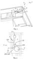
- FIG. 1 shows, by way of example, a fastening device 1 according to a preferred embodiment.
- the fastening device 1 is provided for fastening a luminaire, in particular a pendant luminaire, or another suspended element, in particular an (electrical) device or even a suspended ceiling, to a suspension structure (suspension structure or suspension option) not shown in detail.
- the suspension structure generally hangs from a ceiling vertically or obliquely, for example at an angle of 45° to the vertical.
- the suspension structure preferably has a suspension body provided in particular at the distal end of the suspension structure.
- the suspension structure is designed in the form of a cable suspension.
- the suspension body is designed as a nipple or sphere.
- Other geometries of the suspension body are also conceivable, for example suspension bodies with a polygonal (rectangular, square, etc.) or round (circular, elliptical, etc.) cross-section.
- the fastening device 1 is preferably rectangular in plan view. However, the fastening device 1 can also have any other shape in plan view, for example, a polygonal (square, etc.) or round (circular, elliptical, etc.) shape.
- the fastening device 1 has at least one fastening structure 2.
- the fastening device 1 can also have more than one fastening structure 2, i.e. at least two, preferably three or - as in Figure 1 clearly visible - four fastening structures 2.
- the fastening structures 2 can be evenly distributed over the fastening device 1.
- the fastening structures 2 are formed in the regions delimiting the fastening device 1, such as corner regions 3.
- the fastening device 1 can also have only one fastening structure 2, which then for example, is formed centrally in the fastening device 1. Only one fastening structure 2 is particularly advantageous in the case of a spherical light.
- fastening structures 2 is described as an example.
- the description of this fastening structure 2 applies analogously to the other fastening structure(s) 2, unless otherwise described.
- the fastening structure 2 has an opening 4 through which the suspension structure (partially) or the suspension body of the suspension structure (completely) can be inserted into the fastening device 1.
- the opening 4 is preferably designed to correspond to the suspension structure, in particular to the suspension body, for example round, preferably circular or elliptical. However, the opening 4 can also be polygonal, in particular rectangular or square. The only important thing is that the suspension structure or its suspension body can be inserted into the fastening device 1 through the opening 4.
- the opening 4 preferably has a diameter of 5 mm to 10 mm, particularly preferably 8.5 mm. In other exemplary embodiments, in particular for particularly heavy objects or lights, the diameter can also be over 10 mm.
- a slot 5 is preferably directly connected to the opening 4, so that the suspension structure introduced into the fastening device 1 via the opening 4 can be moved via the slot 5 into a supporting position.
- the suspension structure can thus be moved along the slot 5, but cannot be moved out of the fastening device 1 via the slot 5.
- the slot 5 is designed to be so wide that the suspension body, if present, and thus the suspension structure cannot be guided out of the fastening device 1 via the slot 5.
- the slot 5 is preferably designed to be constant in width along its direction of extension.
- the suspension structure can thus be moved via the slot 5 into a supporting position in which the suspension structure supports the fastening device 1 in a suspended manner.
- the suspension structure preferably reaches the supporting position when the suspension structure comes into force-fitting and/or form-fitting contact with a (defined) contact area.
- the suspension structure reaches the supporting position in particular when it reaches a further opening 6 formed with the fastening structure 2.
- the supporting position is any position in which the suspension structure can support the fastening device in a suspended manner; the supporting position therefore does not include the opening 4 in particular.
- the further opening 6 is therefore also connected to the slot 5.
- the geometry of the further opening 6 can thus hold the suspension structure, in particular its suspension body, in the supporting position.
- the further opening 6 preferably has the contact area.
- the contact area is formed by the circumference of the further opening 6.
- the further opening 6 preferably has a shape corresponding to the suspension structure, in particular the suspension body.
- the further opening 6 is round, preferably circular, or polygonal, preferably rectangular or square.
- the further opening 6 is preferably smaller than the opening 4, so that the suspension structure, in particular its suspension body, cannot be passed through the further opening 6. It is particularly preferred if the further opening 6 has a diameter of 2 mm to 6 mm, for example 4.5 mm.
- the slot 5 has a serrated section 51, which is designed to prevent movement of the suspension structure from the supporting position. In the embodiment shown in the figures, this is achieved in such a way that the serrated extending section 51 has a first sub-section 51a and a second sub-section 51b forming the serrated section 51 or the serrated shape of the section 51.
- the sub-sections 51a, 51b are each preferably designed to run in a straight line.
- the first sub-section 51a preferably runs in the direction of the carrying position or the further opening 6, i.e. is preferably (directly) connected to the further opening 6.
- the second sub-section 51b preferably runs with an extension direction that points neither in the direction of the opening 4 nor in the direction of the carrying position or the further opening 6.
- the sections 51a, 51b extend in such a way that, when the suspension structure supports the fastening device 1 in the supporting position, i.e., when the suspension structure is provided in particular in the region of the further opening 6 or in the first section 51a, movement of the suspension structure from the first section 51a into the second section 51b and thus from the supporting position is prevented.
- This is achieved by selecting the angle between the sections 51a and 51b accordingly, for example, as an acute angle.
- this angle lies in a range of 20° to 70°, preferably in a range of 30° to 50°, for example, substantially 37°.
- the first section 51a is preferably longer than the second section 51b.
- the length of the first section 51a is a multiple of the length of the second section 51b; the first section 51a is therefore preferably elongated.
- the first section 51a can be twice or three times as long as the second section 51b.
- the slot 5 has at least one further serrated section 52 which is connected to the opening 4 and the serrated section 51, so that the opening 4
- the suspension structure inserted into the fastening device 1 can be moved into the carrying position via the further serrated section 52 and the serrated section 51.
- the further serrated section 52 ensures that a movement of the suspension structure from the carrying position, i.e. in particular into the opening 4, can be prevented even better.
- the further serrated section 52 has a (further) first partial section 52a and (further) second partial section 52b forming the further serrated section 52 or the serrated shape of the section 52, wherein, as shown in the Figures 2 and 3
- the (further) second subsection 52b is preferably the second subsection 51b.
- the subsections 52a, 52b are each preferably designed to run in a straight line. Alternatively, however, it can also be provided that the second subsection 51b is indirectly connected to the second subsection 52b.
- the (further) first subsection 52a is preferably (directly) connected to the opening 4.
- the (further) first sub-section 52a and the (further) second sub-section 52b extend in such a way that, when the suspension structure supports the fastening device 1 in the supporting position, a movement of the suspension structure from the (further) second sub-section 52b into the (further) first sub-section 52a and thus from the supporting position or into the opening 4 can be prevented.
- the sub-sections 52a, 52b preferably extend at a defined, in particular acute angle.
- the defined angle between the sub-sections 52a and 52b lies in a range of 70° to 90°.
- the aforementioned angle is substantially 80°.
- the sub-sections 52a, 52b are preferably of substantially equal length.
- Section 52a leads away from opening 4.
- section 51b or 52b leads away from the further opening 6.
- section 51a leads (in a straight line) to the further opening 4.
- the jagged sections 51, 52 thus form a kind of labyrinth, zigzag, or lightning guide, which particularly effectively prevents or impedes the suspension structure from moving out of the supporting position, i.e., in particular, from unintentionally moving the suspension structure into opening 4.
- the slot 5 can also have more than one further serrated section 52, for example two or three further serrated sections, so that, for example, a first sub-section of a further serrated section forming the respective serration is the second sub-section of the serration of the next further serrated section, etc.
- the slot 5 is also designed such that the suspension structure can be driven into the carrying position, i.e. in particular into the further opening 6, by the weight of the fastening device 1.
- this is achieved in that, in a state in which the suspension structure supports the fastening device 1 in the carrying position, the slot 5 extends such that the contact area with which the suspension structure is in contact in the carrying position in order to support the fastening device 1 is arranged higher than the opening 4.
- this is preferably achieved in the embodiment shown in the figures in such a way that the further opening 6 is arranged higher than the opening 4. This means that if the further Opening 6 provides the contact area, the contact area is preferably arranged higher than the opening 4 on the side of the contact area.
- the slot 5 can extend obliquely to the horizontal, so that in particular the aforementioned height difference between opening 4 and the further opening 6 is provided. In this way, the suspension structure can move relative to the fastening device 1 by the weight of the fastening device 1 and be driven into the carrying position.
- the slot 5 preferably runs at an angle of 5° to 15°, particularly preferably at an angle of 10° to the horizontal, when the suspension structure supports the fastening device 1 in the carrying position.
- the fastening structure 2 has a surface 7 which is inclined with respect to the (main extension direction of the) fastening device 1 and in which the slot 5 is formed, so that the slot 5 runs obliquely to the horizontal when the suspension structure supports the fastening device 1 in the carrying position.
- the opening 5 is thus provided at a lower region of the inclination of the surface 7, with the further opening 6 being provided at a higher region of the inclination of the surface 7; the inclination of the surface 7 therefore leads from the opening 5 to the further opening 7.
- the fastening device 1 is preferably made of aluminum. Alternatively or additionally, however, it can also be provided that the fastening device 1 is made of another material, for example, plastic. Preferably, an aluminum die-casting process is used to manufacture the fastening device 1.
- the fastening structure 2 is preferably integral with the fastening device 1, i.e. in particular with the fastening device 1 made from a single cast.
- the slot 5 preferably has both the jagged, labyrinthine, or lightning-shaped design described above and the design such that the suspension structure can be driven into the carrying position by the weight of the fastening device 1. This ensures particularly good securing of the suspension structure in the carrying position. However, in order to adequately secure the suspension structure in the carrying position without separately provided securing means, it is already sufficient according to the invention if the slot 5 only runs in a jagged shape as described above or if the slot 5 is only designed such that the suspension structure can be driven into the carrying position by the weight of the fastening device 1.
- the fastening device 1 can be part of a luminaire housing or partially form the luminaire housing.
- the fastening device 1 can have structures via which parts of the luminaire housing or the luminaire, in particular components for operating the luminaire, such as an operating device, can be accommodated. It is particularly preferred if the fastening device 1 is formed integrally with the luminaire housing.
- the fastening device 1 can also be detachably connected to the luminaire housing, for example via appropriate fastening means such as a clip connection.
Landscapes
- Engineering & Computer Science (AREA)
- General Engineering & Computer Science (AREA)
- Mechanical Engineering (AREA)
- Clamps And Clips (AREA)
Claims (13)
- Boîtier de luminaire présentant un dispositif de fixation (1) destiné à fixer un luminaire, tel que par exemple un luminaire suspendu, à une structure de suspension, comportant au moins une structure de fixation (2), ladite au moins une structure de fixation (2) présentant :une ouverture (4) et une fente (5) reliée à l'ouverture (4), qui sont réalisées de telle sorte qu'une structure de suspension introduite dans le dispositif de fixation (1) par l'intermédiaire de l'ouverture (4) peut être déplacée par l'intermédiaire de la fente (5) dans une position de support, dans laquelle la structure de suspension supporte le dispositif de fixation (1) en suspension, la fente (5) présentant une section (51 ; 52) s'étendant en forme de dentelure afin d'empêcher un déplacement de la structure de suspension à partir de la position de support,• la section (51) s'étendant en forme de dentelure présentant une première et une seconde section partielle (51a, 51b) formant la section (51) s'étendant en forme de dentelure,∘ la première et la seconde section partielle (51a, 51b) s'étendant de telle sorte que, lorsque la structure de suspension supporte le dispositif de fixation (1) dans la position de support, un déplacement de la structure de suspension à partir de la première section partielle (51a) dans la seconde section partielle (51b) et par conséquent à partir de la position de support est empêché etla fente (5) étant réalisée de telle sorte que la structure de suspension (1) peut être entraînée dans la position de support par le poids du dispositif de fixation,caractérisé en ce que l'angle entre la première section partielle (51a) et la seconde section partielle (51b) est situé dans une plage de 20° à 70°,• et en ce que la fente (6) présente une autre section (52) s'étendant en forme de dentelure,l'autre section (52) s'étendant en forme de dentelure étant reliée à l'ouverture (4) et à la section (51) s'étendant en forme de dentelure, de telle sorte que la structure de suspension introduite dans le dispositif de fixation (1) par l'intermédiaire de l'ouverture (4) peut être déplacée dans la position de support par l'intermédiaire de l'autre section (52) s'étendant en forme de dentelure et de la section (51) s'étendant en forme de dentelure et les sections (51, 52) s'étendant en forme de dentelure pouvant empêcher un déplacement de la structure de suspension à partir de la position de support,la fente (5) étant réalisée dans une surface inclinée (7) de la structure de fixation (2) de manière à s'étendre de manière inclinée par rapport à l'horizontale lorsque la structure de suspension supporte le dispositif de fixation (1) dans la position de support.
- Boîtier de luminaire selon la revendication 1,la première section partielle (51a) étant plus longue que la seconde section partielle (51b) et/oul'angle entre la première section partielle (51a) et la seconde section partielle (51b) étant situé dans une plage de 30° à 50°, par exemple étant sensiblement de 37°.
- Boîtier de luminaire selon l'une des revendications précédentes, l'autre section (52) s'étendant en forme de dentelure présentant une autre première et une autre seconde section partielle (52a, 52b) formant l'autre section (52) s'étendant en forme de dentelure, l'autre première section partielle (52a) étant reliée à l'ouverture (4) et l'autre seconde section partielle (52) étant reliée à la section (51) s'étendant en forme de dentelure, l'autre seconde section partielle (52b) de l'autre section (52) s'étendant en forme de dentelure étant de préférence la seconde section partielle (51b) de la section (51) s'étendant en forme de dentelure.
- Boîtier de luminaire selon la revendication 3, l'autre première et l'autre seconde section partielle (52a, 52b) s'étendant de telle sorte que, lorsque la structure de suspension supporte le dispositif de fixation (1) dans la position de support, un déplacement de la structure de suspension à partir de l'autre seconde section partielle (52b) dans l'autre première section partielle (52a) et par conséquent à partir de la position de support peut être empêché, l'angle entre l'autre première section partielle (52a) et l'autre seconde section partielle (52b) étant de préférence situé dans une plage de 70° à 90°, par exemple étant sensiblement de 80°.
- Boîtier de luminaire selon l'une des revendications précédentes, la fente (5) s'étendant de telle sorte qu'une zone de contact, avec laquelle la structure de suspension est en contact dans la position de support pour supporter le dispositif de fixation (1), est disposée plus haut que l'ouverture (4) lorsque la structure de suspension supporte le dispositif de fixation (1) dans la position de support.
- Boîtier de luminaire selon l'une des revendications précédentes, la fente (5) s'étendant de manière inclinée par rapport à l'horizontale lorsque la structure de suspension supporte le dispositif de fixation (1) dans la position de support, de telle sorte que la structure de suspension peut être entraînée dans la position de support par le poids du dispositif de fixation (1), la fente s'étendant de préférence de manière inclinée d'un angle de 5° à 15°, de manière particulièrement préférée d'un angle de 10°, par rapport à l'horizontale lorsque la structure de suspension supporte le dispositif de fixation (1) dans la position de support.
- Boîtier de luminaire selon l'une des revendications précédentes, l'au moins une structure de fixation (2) présentant une autre ouverture (6) qui est reliée à la fente (5), en particulier à la première section partielle (51a) de la section (51) s'étendant en forme de dentelure, et qui est réalisée afin de pouvoir maintenir la structure de suspension dans la position de support, l'autre ouverture (6) présentant de préférence la zone de contact.
- Boîtier de luminaire selon l'une des revendications précédentes, l'ouverture (4) et/ou l'autre ouverture (6) étant réalisée(s) en fonction de la structure de suspension et/ou étant de forme ronde, de préférence circulaire, ou polygonale, de préférence rectangulaire ou carrée et/ou l'ouverture (4) étant plus grande que l'autre ouverture (6), de telle sorte que la structure de suspension peut passer à travers l'ouverture (4) et ne peut pas passer à travers l'autre ouverture (6), l'ouverture (4) présentant de préférence un diamètre de 5 mm à 10 mm, de manière particulièrement préférée de 8,5 mm et/ou l'autre ouverture (6) présentant de préférence un diamètre de 2 mm à 6 mm, de manière particulièrement préférée de 4,5 mm.
- Boîtier de luminaire selon l'une des revendications précédentes, comportant au moins deux, de préférence trois ou quatre structures de fixation (2), qui sont de préférence réparties uniformément sur le dispositif de fixation (1) et/ou sont de préférence réalisées dans des zones délimitant le dispositif de fixation (1), comme par exemple des zones de coin (3).
- Boîtier de luminaire selon l'une des revendications précédentes, le dispositif de fixation (1) étant fabriqué en aluminium, en particulier par un procédé de moulage sous pression d'aluminium, et/ou l'au moins une structure de fixation (2) étant réalisée d'un seul tenant avec le dispositif de fixation (1).
- Boîtier de luminaire selon l'une des revendications précédentes, le dispositif de fixation (1) étant relié d'un seul tenant ou de manière amovible au boîtier de luminaire.
- Luminaire, en particulier luminaire suspendu, présentant un boîtier de luminaire selon l'une des revendications précédentes ainsi qu'au moins une source lumineuse, telle que par exemple une DEL, logée dans le boîtier de luminaire.
- Système d'éclairage présentant un luminaire selon la revendication précédente et une structure de suspension, la structure de suspension, dans la position de support, supportant le dispositif de fixation (1) et donc le luminaire, de telle sorte que le luminaire est fixé à la structure de suspension par l'intermédiaire du dispositif de fixation (1).
Applications Claiming Priority (1)
| Application Number | Priority Date | Filing Date | Title |
|---|---|---|---|
| DE202018106320.0U DE202018106320U1 (de) | 2018-11-07 | 2018-11-07 | Befestigungsvorrichtung |
Publications (2)
| Publication Number | Publication Date |
|---|---|
| EP3650743A1 EP3650743A1 (fr) | 2020-05-13 |
| EP3650743B1 true EP3650743B1 (fr) | 2025-05-07 |
Family
ID=68295929
Family Applications (1)
| Application Number | Title | Priority Date | Filing Date |
|---|---|---|---|
| EP19201618.6A Active EP3650743B1 (fr) | 2018-11-07 | 2019-10-07 | Dispositif de fixation |
Country Status (3)
| Country | Link |
|---|---|
| EP (1) | EP3650743B1 (fr) |
| AT (1) | AT17365U1 (fr) |
| DE (1) | DE202018106320U1 (fr) |
Families Citing this family (1)
| Publication number | Priority date | Publication date | Assignee | Title |
|---|---|---|---|---|
| DE202023103320U1 (de) * | 2023-06-15 | 2024-09-17 | Zumtobel Lighting Gmbh | Pendelleuchte mit Sicherungselement |
Citations (4)
| Publication number | Priority date | Publication date | Assignee | Title |
|---|---|---|---|---|
| JPH08115607A (ja) * | 1994-10-17 | 1996-05-07 | Misawa Homes Co Ltd | コーナー固定照明器具 |
| CN2529002Y (zh) * | 2002-01-29 | 2003-01-01 | 袁青 | 防误取螺钉悬挂槽 |
| WO2017044449A1 (fr) * | 2015-09-09 | 2017-03-16 | Hubbell Incorporated | Ensemble de jonction actionné de l'extérieur destiné à raccorder des structures adjacentes |
| CN207921991U (zh) * | 2018-04-09 | 2018-09-28 | 中山雷士灯饰科技有限公司 | 一种便于安装的灯具结构 |
Family Cites Families (8)
| Publication number | Priority date | Publication date | Assignee | Title |
|---|---|---|---|---|
| DE3729276A1 (de) * | 1987-09-02 | 1989-03-16 | Hoffmeister Leuchten Kg | Vorrichtung zur befestigung von verkleidungsrohren fuer stromschienen mit langfeldleuchten |
| EP1674790B1 (fr) * | 2004-12-20 | 2008-09-10 | Siteco Beleuchtungstechnik GmbH | Système de fixation pour montage de luminaires dans un rail d'éclairage |
| JP2009127795A (ja) * | 2007-11-27 | 2009-06-11 | Victor Co Of Japan Ltd | 部材連結構造及び天井取付器具 |
| JP5565956B2 (ja) * | 2010-09-28 | 2014-08-06 | パナソニック株式会社 | 照明器具 |
| DE202012003859U1 (de) * | 2012-04-16 | 2012-06-18 | Ayal Rosin | Leuchtenaufhängung |
| AT14046U1 (de) * | 2013-10-17 | 2015-03-15 | Zumtobel Lighting Gmbh | Befestigungsvorrichtung für Profilkörper |
| EP2940322B1 (fr) * | 2014-04-30 | 2017-03-22 | Axis AB | Agencement de suspension et dispositif de surveillance comportant ledit agencement |
| AT14937U1 (de) * | 2015-08-10 | 2016-09-15 | Zumtobel Lighting Gmbh | Seilabhängungsvorrichtung |
-
2018
- 2018-11-07 DE DE202018106320.0U patent/DE202018106320U1/de active Active
- 2018-12-05 AT ATGM50250/2018U patent/AT17365U1/de unknown
-
2019
- 2019-10-07 EP EP19201618.6A patent/EP3650743B1/fr active Active
Patent Citations (4)
| Publication number | Priority date | Publication date | Assignee | Title |
|---|---|---|---|---|
| JPH08115607A (ja) * | 1994-10-17 | 1996-05-07 | Misawa Homes Co Ltd | コーナー固定照明器具 |
| CN2529002Y (zh) * | 2002-01-29 | 2003-01-01 | 袁青 | 防误取螺钉悬挂槽 |
| WO2017044449A1 (fr) * | 2015-09-09 | 2017-03-16 | Hubbell Incorporated | Ensemble de jonction actionné de l'extérieur destiné à raccorder des structures adjacentes |
| CN207921991U (zh) * | 2018-04-09 | 2018-09-28 | 中山雷士灯饰科技有限公司 | 一种便于安装的灯具结构 |
Also Published As
| Publication number | Publication date |
|---|---|
| DE202018106320U1 (de) | 2020-02-10 |
| EP3650743A1 (fr) | 2020-05-13 |
| AT17365U1 (de) | 2022-02-15 |
Similar Documents
| Publication | Publication Date | Title |
|---|---|---|
| EP2886946A1 (fr) | Support pour un composant de fonctionnement d'un éclairage | |
| DE102014110192A1 (de) | Befestiger für eine Montageschiene | |
| EP3650743B1 (fr) | Dispositif de fixation | |
| DE112016004037B4 (de) | Befestigungsvorrichtung, vorrangig zur Montage einer Antenne an einem Fahrzeug | |
| DE102009022780B4 (de) | Ständer für rechteckige Solarmodule | |
| EP0622575B1 (fr) | Dispositif de serrage utilisant un collier de fixation ou similaire pour tuyaux | |
| WO2017137261A1 (fr) | Système de bande lumineuse à rail de support de forme allongée | |
| EP2767659B1 (fr) | Guide à barres rondes réglable en hauteur | |
| DE9017373U1 (de) | Schutzrohrsegment für die Zusammensetzung eines Schutzrohrabschnitts für elektrische Leitungskabel | |
| EP0874423B1 (fr) | Fixation pour barre de courant | |
| EP3951114A1 (fr) | Dispositif de fixation | |
| DE4116210C2 (de) | Befestigungssystem für Lichtschrankenelemente | |
| EP2902265B1 (fr) | Support d'écran | |
| DE20207685U1 (de) | Halter | |
| DE29901397U1 (de) | Längliche, im Querschnittsprofil linsenartige Pendel- oder Anbauleuchte | |
| DE19803774C2 (de) | Vorrichtung zum Befestigen von Bauteilen - insbesondere Leuchten und Überwachunskameras - an Masten | |
| AT15349U1 (de) | Drahthalter für eine Leuchte | |
| DE29722471U1 (de) | Einbaudose zum Einsetzen in einen Installationskanal | |
| EP2469162B1 (fr) | Dispositif de support pour une lampe | |
| EP1820752B1 (fr) | Dispositif de fixation destiné à la fixation d'un récipient de collecte sur un profil rond et/ou anguleux ou sur une paroi | |
| EP2383511A2 (fr) | Agencement de fixation d'un objet sur un élément de suspension étiré en longueur | |
| DE2147843C3 (de) | Vorrichtung zur Arretierung einer Schraubenmutter in Profilschienen | |
| AT519482B1 (de) | Hängeklemme | |
| AT14937U1 (de) | Seilabhängungsvorrichtung | |
| AT15688U1 (de) | Haltevorrichtung mit Tragschiene und Halteelement für die Tragschiene |
Legal Events
| Date | Code | Title | Description |
|---|---|---|---|
| PUAI | Public reference made under article 153(3) epc to a published international application that has entered the european phase |
Free format text: ORIGINAL CODE: 0009012 |
|
| STAA | Information on the status of an ep patent application or granted ep patent |
Free format text: STATUS: THE APPLICATION HAS BEEN PUBLISHED |
|
| AK | Designated contracting states |
Kind code of ref document: A1 Designated state(s): AL AT BE BG CH CY CZ DE DK EE ES FI FR GB GR HR HU IE IS IT LI LT LU LV MC MK MT NL NO PL PT RO RS SE SI SK SM TR |
|
| AX | Request for extension of the european patent |
Extension state: BA ME |
|
| STAA | Information on the status of an ep patent application or granted ep patent |
Free format text: STATUS: REQUEST FOR EXAMINATION WAS MADE |
|
| 17P | Request for examination filed |
Effective date: 20200819 |
|
| RBV | Designated contracting states (corrected) |
Designated state(s): AL AT BE BG CH CY CZ DE DK EE ES FI FR GB GR HR HU IE IS IT LI LT LU LV MC MK MT NL NO PL PT RO RS SE SI SK SM TR |
|
| STAA | Information on the status of an ep patent application or granted ep patent |
Free format text: STATUS: EXAMINATION IS IN PROGRESS |
|
| 17Q | First examination report despatched |
Effective date: 20210611 |
|
| GRAP | Despatch of communication of intention to grant a patent |
Free format text: ORIGINAL CODE: EPIDOSNIGR1 |
|
| STAA | Information on the status of an ep patent application or granted ep patent |
Free format text: STATUS: GRANT OF PATENT IS INTENDED |
|
| INTG | Intention to grant announced |
Effective date: 20250107 |
|
| GRAS | Grant fee paid |
Free format text: ORIGINAL CODE: EPIDOSNIGR3 |
|
| GRAA | (expected) grant |
Free format text: ORIGINAL CODE: 0009210 |
|
| STAA | Information on the status of an ep patent application or granted ep patent |
Free format text: STATUS: THE PATENT HAS BEEN GRANTED |
|
| P01 | Opt-out of the competence of the unified patent court (upc) registered |
Free format text: CASE NUMBER: APP_11211/2025 Effective date: 20250306 |
|
| AK | Designated contracting states |
Kind code of ref document: B1 Designated state(s): AL AT BE BG CH CY CZ DE DK EE ES FI FR GB GR HR HU IE IS IT LI LT LU LV MC MK MT NL NO PL PT RO RS SE SI SK SM TR |
|
| REG | Reference to a national code |
Ref country code: GB Ref legal event code: FG4D Free format text: NOT ENGLISH |
|
| REG | Reference to a national code |
Ref country code: CH Ref legal event code: EP |
|
| REG | Reference to a national code |
Ref country code: DE Ref legal event code: R096 Ref document number: 502019013311 Country of ref document: DE |
|
| REG | Reference to a national code |
Ref country code: IE Ref legal event code: FG4D Free format text: LANGUAGE OF EP DOCUMENT: GERMAN |
|
| REG | Reference to a national code |
Ref country code: DE Ref legal event code: R084 Ref document number: 502019013311 Country of ref document: DE |
|
| REG | Reference to a national code |
Ref country code: NL Ref legal event code: MP Effective date: 20250507 |
|
| PG25 | Lapsed in a contracting state [announced via postgrant information from national office to epo] |
Ref country code: PT Free format text: LAPSE BECAUSE OF FAILURE TO SUBMIT A TRANSLATION OF THE DESCRIPTION OR TO PAY THE FEE WITHIN THE PRESCRIBED TIME-LIMIT Effective date: 20250908 Ref country code: ES Free format text: LAPSE BECAUSE OF FAILURE TO SUBMIT A TRANSLATION OF THE DESCRIPTION OR TO PAY THE FEE WITHIN THE PRESCRIBED TIME-LIMIT Effective date: 20250507 Ref country code: FI Free format text: LAPSE BECAUSE OF FAILURE TO SUBMIT A TRANSLATION OF THE DESCRIPTION OR TO PAY THE FEE WITHIN THE PRESCRIBED TIME-LIMIT Effective date: 20250507 |
|
| REG | Reference to a national code |
Ref country code: LT Ref legal event code: MG9D |
|
| PG25 | Lapsed in a contracting state [announced via postgrant information from national office to epo] |
Ref country code: GR Free format text: LAPSE BECAUSE OF FAILURE TO SUBMIT A TRANSLATION OF THE DESCRIPTION OR TO PAY THE FEE WITHIN THE PRESCRIBED TIME-LIMIT Effective date: 20250808 Ref country code: NO Free format text: LAPSE BECAUSE OF FAILURE TO SUBMIT A TRANSLATION OF THE DESCRIPTION OR TO PAY THE FEE WITHIN THE PRESCRIBED TIME-LIMIT Effective date: 20250807 |
|
| PG25 | Lapsed in a contracting state [announced via postgrant information from national office to epo] |
Ref country code: PL Free format text: LAPSE BECAUSE OF FAILURE TO SUBMIT A TRANSLATION OF THE DESCRIPTION OR TO PAY THE FEE WITHIN THE PRESCRIBED TIME-LIMIT Effective date: 20250507 Ref country code: NL Free format text: LAPSE BECAUSE OF FAILURE TO SUBMIT A TRANSLATION OF THE DESCRIPTION OR TO PAY THE FEE WITHIN THE PRESCRIBED TIME-LIMIT Effective date: 20250507 |
|
| PG25 | Lapsed in a contracting state [announced via postgrant information from national office to epo] |
Ref country code: BG Free format text: LAPSE BECAUSE OF FAILURE TO SUBMIT A TRANSLATION OF THE DESCRIPTION OR TO PAY THE FEE WITHIN THE PRESCRIBED TIME-LIMIT Effective date: 20250507 |
|
| PG25 | Lapsed in a contracting state [announced via postgrant information from national office to epo] |
Ref country code: HR Free format text: LAPSE BECAUSE OF FAILURE TO SUBMIT A TRANSLATION OF THE DESCRIPTION OR TO PAY THE FEE WITHIN THE PRESCRIBED TIME-LIMIT Effective date: 20250507 |
|
| PG25 | Lapsed in a contracting state [announced via postgrant information from national office to epo] |
Ref country code: RS Free format text: LAPSE BECAUSE OF FAILURE TO SUBMIT A TRANSLATION OF THE DESCRIPTION OR TO PAY THE FEE WITHIN THE PRESCRIBED TIME-LIMIT Effective date: 20250807 |
|
| PG25 | Lapsed in a contracting state [announced via postgrant information from national office to epo] |
Ref country code: IS Free format text: LAPSE BECAUSE OF FAILURE TO SUBMIT A TRANSLATION OF THE DESCRIPTION OR TO PAY THE FEE WITHIN THE PRESCRIBED TIME-LIMIT Effective date: 20250907 |
|
| PG25 | Lapsed in a contracting state [announced via postgrant information from national office to epo] |
Ref country code: LV Free format text: LAPSE BECAUSE OF FAILURE TO SUBMIT A TRANSLATION OF THE DESCRIPTION OR TO PAY THE FEE WITHIN THE PRESCRIBED TIME-LIMIT Effective date: 20250507 |
|
| PGFP | Annual fee paid to national office [announced via postgrant information from national office to epo] |
Ref country code: DE Payment date: 20251028 Year of fee payment: 7 |
|
| PGFP | Annual fee paid to national office [announced via postgrant information from national office to epo] |
Ref country code: GB Payment date: 20251023 Year of fee payment: 7 |
|
| PG25 | Lapsed in a contracting state [announced via postgrant information from national office to epo] |
Ref country code: SM Free format text: LAPSE BECAUSE OF FAILURE TO SUBMIT A TRANSLATION OF THE DESCRIPTION OR TO PAY THE FEE WITHIN THE PRESCRIBED TIME-LIMIT Effective date: 20250507 Ref country code: DK Free format text: LAPSE BECAUSE OF FAILURE TO SUBMIT A TRANSLATION OF THE DESCRIPTION OR TO PAY THE FEE WITHIN THE PRESCRIBED TIME-LIMIT Effective date: 20250507 |
|
| PGFP | Annual fee paid to national office [announced via postgrant information from national office to epo] |
Ref country code: FR Payment date: 20251027 Year of fee payment: 7 |
|
| PG25 | Lapsed in a contracting state [announced via postgrant information from national office to epo] |
Ref country code: CZ Free format text: LAPSE BECAUSE OF FAILURE TO SUBMIT A TRANSLATION OF THE DESCRIPTION OR TO PAY THE FEE WITHIN THE PRESCRIBED TIME-LIMIT Effective date: 20250507 |
|
| PG25 | Lapsed in a contracting state [announced via postgrant information from national office to epo] |
Ref country code: EE Free format text: LAPSE BECAUSE OF FAILURE TO SUBMIT A TRANSLATION OF THE DESCRIPTION OR TO PAY THE FEE WITHIN THE PRESCRIBED TIME-LIMIT Effective date: 20250507 |
|
| PG25 | Lapsed in a contracting state [announced via postgrant information from national office to epo] |
Ref country code: SK Free format text: LAPSE BECAUSE OF FAILURE TO SUBMIT A TRANSLATION OF THE DESCRIPTION OR TO PAY THE FEE WITHIN THE PRESCRIBED TIME-LIMIT Effective date: 20250507 Ref country code: RO Free format text: LAPSE BECAUSE OF FAILURE TO SUBMIT A TRANSLATION OF THE DESCRIPTION OR TO PAY THE FEE WITHIN THE PRESCRIBED TIME-LIMIT Effective date: 20250507 |
|
| PG25 | Lapsed in a contracting state [announced via postgrant information from national office to epo] |
Ref country code: IT Free format text: LAPSE BECAUSE OF FAILURE TO SUBMIT A TRANSLATION OF THE DESCRIPTION OR TO PAY THE FEE WITHIN THE PRESCRIBED TIME-LIMIT Effective date: 20250507 |
|
| REG | Reference to a national code |
Ref country code: DE Ref legal event code: R097 Ref document number: 502019013311 Country of ref document: DE |
|
| PLBE | No opposition filed within time limit |
Free format text: ORIGINAL CODE: 0009261 |
|
| STAA | Information on the status of an ep patent application or granted ep patent |
Free format text: STATUS: NO OPPOSITION FILED WITHIN TIME LIMIT |
|
| REG | Reference to a national code |
Ref country code: CH Ref legal event code: L10 Free format text: ST27 STATUS EVENT CODE: U-0-0-L10-L00 (AS PROVIDED BY THE NATIONAL OFFICE) Effective date: 20260318 |
|
| 26N | No opposition filed |
Effective date: 20260210 |