EP3652111B1 - Films minces polymères électrochromiques ayant un comportement d'auto-blanchiment réduit et une stabilité de cycle améliorée - Google Patents
Films minces polymères électrochromiques ayant un comportement d'auto-blanchiment réduit et une stabilité de cycle améliorée Download PDFInfo
- Publication number
- EP3652111B1 EP3652111B1 EP18832949.4A EP18832949A EP3652111B1 EP 3652111 B1 EP3652111 B1 EP 3652111B1 EP 18832949 A EP18832949 A EP 18832949A EP 3652111 B1 EP3652111 B1 EP 3652111B1
- Authority
- EP
- European Patent Office
- Prior art keywords
- ecp
- ito
- substrate
- film
- ito substrate
- Prior art date
- Legal status (The legal status is an assumption and is not a legal conclusion. Google has not performed a legal analysis and makes no representation as to the accuracy of the status listed.)
- Active
Links
Images



Classifications
-
- C—CHEMISTRY; METALLURGY
- C09—DYES; PAINTS; POLISHES; NATURAL RESINS; ADHESIVES; COMPOSITIONS NOT OTHERWISE PROVIDED FOR; APPLICATIONS OF MATERIALS NOT OTHERWISE PROVIDED FOR
- C09K—MATERIALS FOR MISCELLANEOUS APPLICATIONS, NOT PROVIDED FOR ELSEWHERE
- C09K9/00—Tenebrescent materials, i.e. materials for which the range of wavelengths for energy absorption is changed as a result of excitation by some form of energy
- C09K9/02—Organic tenebrescent materials
-
- G—PHYSICS
- G02—OPTICS
- G02F—OPTICAL DEVICES OR ARRANGEMENTS FOR THE CONTROL OF LIGHT BY MODIFICATION OF THE OPTICAL PROPERTIES OF THE MEDIA OF THE ELEMENTS INVOLVED THEREIN; NON-LINEAR OPTICS; FREQUENCY-CHANGING OF LIGHT; OPTICAL LOGIC ELEMENTS; OPTICAL ANALOGUE/DIGITAL CONVERTERS
- G02F1/00—Devices or arrangements for the control of the intensity, colour, phase, polarisation or direction of light arriving from an independent light source, e.g. switching, gating or modulating; Non-linear optics
- G02F1/01—Devices or arrangements for the control of the intensity, colour, phase, polarisation or direction of light arriving from an independent light source, e.g. switching, gating or modulating; Non-linear optics for the control of the intensity, phase, polarisation or colour
- G02F1/15—Devices or arrangements for the control of the intensity, colour, phase, polarisation or direction of light arriving from an independent light source, e.g. switching, gating or modulating; Non-linear optics for the control of the intensity, phase, polarisation or colour based on an electrochromic effect
- G02F1/153—Constructional details
- G02F1/155—Electrodes
-
- C—CHEMISTRY; METALLURGY
- C08—ORGANIC MACROMOLECULAR COMPOUNDS; THEIR PREPARATION OR CHEMICAL WORKING-UP; COMPOSITIONS BASED THEREON
- C08G—MACROMOLECULAR COMPOUNDS OBTAINED OTHERWISE THAN BY REACTIONS ONLY INVOLVING UNSATURATED CARBON-TO-CARBON BONDS
- C08G61/00—Macromolecular compounds obtained by reactions forming a carbon-to-carbon link in the main chain of the macromolecule
- C08G61/12—Macromolecular compounds containing atoms other than carbon in the main chain of the macromolecule
- C08G61/122—Macromolecular compounds containing atoms other than carbon in the main chain of the macromolecule derived from five- or six-membered heterocyclic compounds, other than imides
- C08G61/123—Macromolecular compounds containing atoms other than carbon in the main chain of the macromolecule derived from five- or six-membered heterocyclic compounds, other than imides derived from five-membered heterocyclic compounds
- C08G61/126—Macromolecular compounds containing atoms other than carbon in the main chain of the macromolecule derived from five- or six-membered heterocyclic compounds, other than imides derived from five-membered heterocyclic compounds with a five-membered ring containing one sulfur atom in the ring
-
- G—PHYSICS
- G02—OPTICS
- G02F—OPTICAL DEVICES OR ARRANGEMENTS FOR THE CONTROL OF LIGHT BY MODIFICATION OF THE OPTICAL PROPERTIES OF THE MEDIA OF THE ELEMENTS INVOLVED THEREIN; NON-LINEAR OPTICS; FREQUENCY-CHANGING OF LIGHT; OPTICAL LOGIC ELEMENTS; OPTICAL ANALOGUE/DIGITAL CONVERTERS
- G02F1/00—Devices or arrangements for the control of the intensity, colour, phase, polarisation or direction of light arriving from an independent light source, e.g. switching, gating or modulating; Non-linear optics
- G02F1/01—Devices or arrangements for the control of the intensity, colour, phase, polarisation or direction of light arriving from an independent light source, e.g. switching, gating or modulating; Non-linear optics for the control of the intensity, phase, polarisation or colour
- G02F1/13—Devices or arrangements for the control of the intensity, colour, phase, polarisation or direction of light arriving from an independent light source, e.g. switching, gating or modulating; Non-linear optics for the control of the intensity, phase, polarisation or colour based on liquid crystals, e.g. single liquid crystal display cells
- G02F1/133—Constructional arrangements; Operation of liquid crystal cells; Circuit arrangements
- G02F1/1333—Constructional arrangements; Manufacturing methods
- G02F1/1343—Electrodes
- G02F1/13439—Electrodes characterised by their electrical, optical, physical properties; materials therefor; method of making
-
- G—PHYSICS
- G02—OPTICS
- G02F—OPTICAL DEVICES OR ARRANGEMENTS FOR THE CONTROL OF LIGHT BY MODIFICATION OF THE OPTICAL PROPERTIES OF THE MEDIA OF THE ELEMENTS INVOLVED THEREIN; NON-LINEAR OPTICS; FREQUENCY-CHANGING OF LIGHT; OPTICAL LOGIC ELEMENTS; OPTICAL ANALOGUE/DIGITAL CONVERTERS
- G02F1/00—Devices or arrangements for the control of the intensity, colour, phase, polarisation or direction of light arriving from an independent light source, e.g. switching, gating or modulating; Non-linear optics
- G02F1/01—Devices or arrangements for the control of the intensity, colour, phase, polarisation or direction of light arriving from an independent light source, e.g. switching, gating or modulating; Non-linear optics for the control of the intensity, phase, polarisation or colour
- G02F1/15—Devices or arrangements for the control of the intensity, colour, phase, polarisation or direction of light arriving from an independent light source, e.g. switching, gating or modulating; Non-linear optics for the control of the intensity, phase, polarisation or colour based on an electrochromic effect
- G02F1/153—Constructional details
- G02F1/1533—Constructional details structural features not otherwise provided for
-
- C—CHEMISTRY; METALLURGY
- C08—ORGANIC MACROMOLECULAR COMPOUNDS; THEIR PREPARATION OR CHEMICAL WORKING-UP; COMPOSITIONS BASED THEREON
- C08G—MACROMOLECULAR COMPOUNDS OBTAINED OTHERWISE THAN BY REACTIONS ONLY INVOLVING UNSATURATED CARBON-TO-CARBON BONDS
- C08G2261/00—Macromolecular compounds obtained by reactions forming a carbon-to-carbon link in the main chain of the macromolecule
- C08G2261/10—Definition of the polymer structure
- C08G2261/14—Side-groups
- C08G2261/149—Side-chains having heteroaromatic units
-
- C—CHEMISTRY; METALLURGY
- C08—ORGANIC MACROMOLECULAR COMPOUNDS; THEIR PREPARATION OR CHEMICAL WORKING-UP; COMPOSITIONS BASED THEREON
- C08G—MACROMOLECULAR COMPOUNDS OBTAINED OTHERWISE THAN BY REACTIONS ONLY INVOLVING UNSATURATED CARBON-TO-CARBON BONDS
- C08G2261/00—Macromolecular compounds obtained by reactions forming a carbon-to-carbon link in the main chain of the macromolecule
- C08G2261/30—Monomer units or repeat units incorporating structural elements in the main chain
- C08G2261/31—Monomer units or repeat units incorporating structural elements in the main chain incorporating aromatic structural elements in the main chain
- C08G2261/314—Condensed aromatic systems, e.g. perylene, anthracene or pyrene
-
- C—CHEMISTRY; METALLURGY
- C08—ORGANIC MACROMOLECULAR COMPOUNDS; THEIR PREPARATION OR CHEMICAL WORKING-UP; COMPOSITIONS BASED THEREON
- C08G—MACROMOLECULAR COMPOUNDS OBTAINED OTHERWISE THAN BY REACTIONS ONLY INVOLVING UNSATURATED CARBON-TO-CARBON BONDS
- C08G2261/00—Macromolecular compounds obtained by reactions forming a carbon-to-carbon link in the main chain of the macromolecule
- C08G2261/30—Monomer units or repeat units incorporating structural elements in the main chain
- C08G2261/32—Monomer units or repeat units incorporating structural elements in the main chain incorporating heteroaromatic structural elements in the main chain
- C08G2261/324—Monomer units or repeat units incorporating structural elements in the main chain incorporating heteroaromatic structural elements in the main chain condensed
- C08G2261/3243—Monomer units or repeat units incorporating structural elements in the main chain incorporating heteroaromatic structural elements in the main chain condensed containing one or more sulfur atoms as the only heteroatom, e.g. benzothiophene
-
- C—CHEMISTRY; METALLURGY
- C08—ORGANIC MACROMOLECULAR COMPOUNDS; THEIR PREPARATION OR CHEMICAL WORKING-UP; COMPOSITIONS BASED THEREON
- C08G—MACROMOLECULAR COMPOUNDS OBTAINED OTHERWISE THAN BY REACTIONS ONLY INVOLVING UNSATURATED CARBON-TO-CARBON BONDS
- C08G2261/00—Macromolecular compounds obtained by reactions forming a carbon-to-carbon link in the main chain of the macromolecule
- C08G2261/90—Applications
-
- G—PHYSICS
- G02—OPTICS
- G02F—OPTICAL DEVICES OR ARRANGEMENTS FOR THE CONTROL OF LIGHT BY MODIFICATION OF THE OPTICAL PROPERTIES OF THE MEDIA OF THE ELEMENTS INVOLVED THEREIN; NON-LINEAR OPTICS; FREQUENCY-CHANGING OF LIGHT; OPTICAL LOGIC ELEMENTS; OPTICAL ANALOGUE/DIGITAL CONVERTERS
- G02F1/00—Devices or arrangements for the control of the intensity, colour, phase, polarisation or direction of light arriving from an independent light source, e.g. switching, gating or modulating; Non-linear optics
- G02F1/01—Devices or arrangements for the control of the intensity, colour, phase, polarisation or direction of light arriving from an independent light source, e.g. switching, gating or modulating; Non-linear optics for the control of the intensity, phase, polarisation or colour
- G02F1/15—Devices or arrangements for the control of the intensity, colour, phase, polarisation or direction of light arriving from an independent light source, e.g. switching, gating or modulating; Non-linear optics for the control of the intensity, phase, polarisation or colour based on an electrochromic effect
- G02F1/1514—Devices or arrangements for the control of the intensity, colour, phase, polarisation or direction of light arriving from an independent light source, e.g. switching, gating or modulating; Non-linear optics for the control of the intensity, phase, polarisation or colour based on an electrochromic effect characterised by the electrochromic material, e.g. by the electrodeposited material
- G02F1/1516—Devices or arrangements for the control of the intensity, colour, phase, polarisation or direction of light arriving from an independent light source, e.g. switching, gating or modulating; Non-linear optics for the control of the intensity, phase, polarisation or colour based on an electrochromic effect characterised by the electrochromic material, e.g. by the electrodeposited material comprising organic material
- G02F1/15165—Polymers
-
- G—PHYSICS
- G02—OPTICS
- G02F—OPTICAL DEVICES OR ARRANGEMENTS FOR THE CONTROL OF LIGHT BY MODIFICATION OF THE OPTICAL PROPERTIES OF THE MEDIA OF THE ELEMENTS INVOLVED THEREIN; NON-LINEAR OPTICS; FREQUENCY-CHANGING OF LIGHT; OPTICAL LOGIC ELEMENTS; OPTICAL ANALOGUE/DIGITAL CONVERTERS
- G02F1/00—Devices or arrangements for the control of the intensity, colour, phase, polarisation or direction of light arriving from an independent light source, e.g. switching, gating or modulating; Non-linear optics
- G02F1/01—Devices or arrangements for the control of the intensity, colour, phase, polarisation or direction of light arriving from an independent light source, e.g. switching, gating or modulating; Non-linear optics for the control of the intensity, phase, polarisation or colour
- G02F1/15—Devices or arrangements for the control of the intensity, colour, phase, polarisation or direction of light arriving from an independent light source, e.g. switching, gating or modulating; Non-linear optics for the control of the intensity, phase, polarisation or colour based on an electrochromic effect
- G02F1/153—Constructional details
- G02F1/1533—Constructional details structural features not otherwise provided for
- G02F2001/1536—Constructional details structural features not otherwise provided for additional, e.g. protective, layer inside the cell
Definitions
- the disclosure relates generally to electrochromic devices, and more particularly, to electrochromic devices having electrochromic polymer (ECP) thin films with suppressed self-bleaching behavior.
- ECP electrochromic polymer
- Electrochromism refers to a reversible optical spectrum change upon an electron transfer reaction induced via an application of voltage. Electrochromic thin films which can manipulate light transmission by switching a small voltage bias to oxidize/reduce the active materials have been developed for decades. Various types of the active materials, including inorganic materials (e.g. WO 3 , MoO 3 , V 2 O 5 , Nb 2 O 5 , etc.), small molecules (e.g. viologens, Prussian blue, etc.), conjugated polymers and inorganic-organic hybrids have been explored. Among them, conjugated polymers present many attractive properties such as fast coloringbleaching time, low cost, and flexibility. However, there are also a few obstacles to overcome, including cycling stability, photo-stability, optical memory, etc. Despite of considerable progresses towards a development of polymer-based electrochromics, there are still several technological hurdles.
- inorganic materials e.g. WO 3 , MoO 3 , V 2 O 5 , N
- the optical memory is the ability of an electrochromic material to maintain its colored/bleached state at an open circuit.
- conjugated polymer thin films generally have good adhesion on device electrodes, a self-bleaching behavior of conjugated polymer often exists, and it has not been fully understood.
- a self-bleaching behavior refers to a phenomena that an electrochromic material resumes its bleached state from a colored state with an application of voltage.
- the self-bleaching behavior hinders the applications of electrochromic devices (ECDs) in many scenarios. For instance, transmissivity of smart windows is required to be precisely controlled based on variations of solar radiation. Because of the self-bleaching behavior, an automatic control becomes more challenging. Therefore, it is important to understand and solve the self-bleaching behaviors of conjugated polymers.
- JP2009145461 discloses a method of manufacturing an electrochemical display element, comprising processing an injection hole for an electrolyte using a silane coupling agent.
- Electrochromic devices and thin film transistors from a new family of ethylenedioxythiophene based conjugated polymers discloses soaking a silicon dioxide substrate in OTS/hexane dilute solution (1: 750 vol. ratio) for 30 minutes to enhance surface hydrophobicity in fabrication of a FET.
- the invention is set out in the appended claims and provides an electrochromic device, a method for preparing an electrochromic device and a method for suppressing a self-bleaching behaviour of an electrochromic polymer film.
- the electrochromic devices disclosed herein may be smart windows or display devices, e.g., anti-glare car mirrors; smart windows configured to modulate the transmission or reflected solar radiation for use in cars, aircrafts, buildings, and the like; protective eyewear; camouflage and/or chameleonic materials; etc.
- compositions and methods include the recited elements, but not excluding others.
- Consisting essentially of' when used to define compositions and methods shall mean excluding other elements of any essential significance to the combination. For example, a composition consisting essentially of the elements as defined herein would not exclude other elements that do not materially affect the basic and novel characteristic(s) of the claimed invention.
- Consisting of shall mean excluding more than trace amount of other ingredients and substantial method steps recited. Embodiments defined by each of these transition terms are within the scope of this invention.
- alkyl refers to a straight or branched hydrocarbon chain radical consisting solely of carbon (C) and hydrogen (H) atoms, which is saturated or unsaturated (i.e., contains one or more double and/or triple bonds).
- alkyl has from 1 to 30 carbon atoms (C 1 -C 30 alkyl), and which is attached to the rest of the molecule by a single bond, e.g., methyl, ethyl, n -propyl, 1-methylethyl ( iso -propyl), n -butyl, n -pentyl, 1,1-dimethylethyl ( t -butyl), 3-methylhexyl, 2-methylhexyl, ethenyl, prop-1-enyl, but-1-enyl, pent-1-enyl, penta-1,4-dienyl, ethynyl, propynyl, butynyl
- alkyl is a straight or branched hydrocarbon chain radical having 1 to 24 carbon atoms (C 1 -C 24 alkyl), 1 to 10 carbon atoms (C 1 -C 10 alkyl), 1 to 6 carbon atoms (C 1 -C 6 alkyl), or 1 to 4 carbon atoms (C 1 -C 4 alkyl).
- ECP films having low self-bleaching and/or enhanced cycling stability and electrochromic devices comprising the ECP films are provided.
- the ECP films have a percentage change of the optical density ( ⁇ OD/OD (%)) of no more than about 15% or about 10% after 120 seconds under V off .
- the ECP films have a percentage change of the optical density ( ⁇ OD/OD (%)) of no more than about 20% or about 10% after 900 seconds under V off .
- the ECP films have a cycling stability of maintaining at least about 95% of color contrast after about 1000 redox cycles or more.
- provided is a method for suppressing the self-bleaching behavior of an ECP film comprising applying a cathodic polarization.
- a method for preparing an electrochromic device comprising applying a cathodic polarization for at least about 60 seconds.
- the cathodic polarization is applied for at least about 60 seconds, or at least about 120 seconds, or at least about 150 seconds, or at least about 180 seconds, or at least about 210 seconds, or at least about 240 seconds or at least about 270 seconds, or at least about 300 seconds. In some embodiments, the cathodic polarization is applied for about 60 seconds to about 360 seconds. In some embodiments, the cathodic polarization is applied for about 300 seconds. In some embodiments, the polarization potential is from about -0.1 V to about -0.5 V, or from about -0.1 V to about -0.4 V, about -0.1 V to about -0.3 V, or about -0.2 V.
- the ECP film is capable of maintaining a colored state for at least 300 seconds or at least 600 seconds. In some embodiments, the ECP film has a percentage change of the optical density ( ⁇ OD/OD (%)) under V off of no more than about 15% or about 10% after 120 seconds. In some embodiments, the ECP film has a percentage change of the optical density ( ⁇ OD/OD (%)) under V off of no more than about 5 % after 120 seconds.
- an electrochromic device comprising an electrochromic polymer (ECP) film on a modified transparent conductive oxide substrate which is a transparent conductive oxide (TCO) substrate partially or fully covered with a modification material selected from C 6 -C 24 alkyltrichlorosilane, TiO 2 , ZnO, WO 3 , MoOs, V 2 O 5 , NiO, Ni 2 O 3 , and Ni 3 O 4 , HMDS (bis(trimethylsilyl)amine), APTS ((3-aminopropyl)triethoxysilane), and trimethoxy(2-phenylethyl)silane, poly(vinylidene fluoride-co-hexafluoropropylene) (PVDF-HFP), poly(3,4-ethylenedioxythiophene)-poly(styrenesulfonate) (PEDOT:PSS), or a combination thereof.
- a modification material selected from C 6 -C 24 alkyltrichlor
- the transparent conductive oxide substrate comprises indium tin oxide (ITO), fluorine-doped tin oxide (FTO), aluminium-doped zinc oxide (AZO), or antimony-doped tin oxide (ATO), or a mixture thereof.
- the transparent conductive oxide substrate comprises ITO.
- the transparent conductive oxide substrate comprises FTO.
- the transparent conductive oxide substrate comprises ATO.
- the transparent conductive oxide substrate comprises AZO.
- the modification material comprises TiO 2 . In some embodiments, the modification material comprises ZnO. In some embodiments, the modification material comprises WO 3 . In some embodiments, the modification material comprises MoOs. In some embodiments, the modification material comprises V 2 O 5 . In some embodiments, the modification material comprises NiO. In some embodiments, the modification material comprises Ni 2 O 3 . In some embodiments, the modification material comprises Ni 3 O 4 . In some embodiments, the modification material comprises HMDS (bis(trimethylsilyl)amine). In some embodiments, the modification material comprises APTS ((3-aminopropyl)triethoxysilane). In some embodiments, the modification material comprises trimethoxy(2-phenylethyl)silane.
- the modification material comprises poly(vinylidene fluoride-co-hexafluoropropylene) (PVDF-HFP). In some embodiments, the modification material comprises poly(3,4-ethylenedioxythiophene)-poly(styrenesulfonate) (PEDOT:PSS).
- the modification material comprises C 6 -C 24 alkyltrichlorosilane. In some embodiments, the modification material comprises C 10 -C 20 alkyltrichlorosilane. In some embodiments, the alkyl is saturated straight or branched hydrocarbon chain. In some embodiments, the alkyl is saturated straight hydrocarbon chain.
- the modification material comprises octadecyltrichlorosilane (OTS).
- the modification material is in the form of a thin layer. In some embodiments, the modification material forms a self-assembled monolayer on the TCO substrate.
- the thickness of a thin layer is less than about 100 nm or less than about 50 nm, or less than about 20 nm, or less than about 10 nm.
- the transparent conductive oxide substrate is fully covered with the modification material. In some embodiments, the transparent conductive oxide substrate is partially covered with the modification material. In some embodiments, about 40%, 35%, 30%, 25%, 20%, 15%, or 10%, or any range between any two of the numbers (end points inclusive), of the transparent conductive oxide substrate is covered with the modification material. According to the invention, the coverage of the modification material on the transparent conductive oxide substrate is between about 10% to about 40%.
- the modified TCO substrate has a higher hydrophobicity than an unmodified TCO substrate.
- the modified TCO substrate has contact angles of at least 100°, or at least 110°, such as about 116°.
- an electrochromic device wherein the self-bleaching behavior of an electrochromic polymer (ECP) film is suppressed, the ECD comprising:
- an electrochromic device wherein the self-bleaching behavior of an electrochromic polymer (ECP) film is suppressed, the ECD comprising:
- the period of time is about 80 minutes.
- a method for preparing an electrochromic device comprising forming an electrochromic polymer film on modified TCO substrate partially or fully covered with a modification material.
- a method for preparing an electrochromic device comprising forming an electrochromic polymer film on an indium tin oxide substrate partially covered with octadecyltrichlorosilane.
- ECP electrochromic polymer
- the obtaining the POTS-ITO substrate comprises immersing the ITO substrate in an OTS hexane solution for about 80 minutes.
- the concentration of the OTS hexane solution is about 1 vol%.
- the method further comprises cleaning the ITO substrate prior to immersing the ITO substrate in the OTS hexane solution.
- cleaning the ITO substrate comprises
- cleaning the ITO substrate comprises
- the method further comprises applying a cathodic polarization as described herein.
- the OTS coverage on the ITO substrate is between about 10% to about 40%.
- the OTS forms a self-assembled monolayer on the ITO substrate.
- the thickness of the OTS layer is about 2 nm to about 4 nm.
- the POTS-ITO substrate has a higher hydrophobicity than the ITO substrate.
- the ITO substrate has contact angles of at least 100°, or at least 110°, such as about 116°.
- the ECP film on a modified transparent conductive oxide substrate such as a POTS-ITO substrate, has a cycling stability that is higher than that of the ECP film on an unmodified transparent conductive oxide substrate, such as an unmodified ITO substrate.
- the ECP film is further treated with a cathodic polarization for about 60 seconds to about 360 seconds, such as at least about 60 seconds, or at least about 120 seconds, or at least about 150 seconds, or at least about 180 seconds, or at least about 210 seconds, or at least about 240 seconds, or at least about 270 seconds, or at least about 300 seconds.
- the ECP film is further treated with a cathodic polarization for about 300 seconds.
- the polarization potential is from about -0.1 V to about -0.5 V, or from about -0.1 V to about -0.4 V, about -0.1 V to about -0.3 V, or about -0.2 V.
- the ECP film on a modified transparent conductive oxide substrate, such as a POTS-ITO substrate, with cathodic polarization is capable of maintaining a colored state for at least about 600 seconds or at least about 900 seconds.
- the ECP film has a percentage change of the optical density ( ⁇ OD/OD (%)) under V off of no more than about 20% or about 10% after 900 seconds.
- the ECP film has a percentage change of the optical density ( ⁇ OD/OD (%)) under V off of no more than about 8 % after 900 seconds.
- the modified transparent conductive oxide substrate shows a lower peak current density than an unmodified transparent conductive oxide substrate, such as an unmodified ITO substrate, in a cyclic voltammetry measurement.
- the modified transparent conductive oxide substrate such as a POTS-ITO substrate
- the modified transparent conductive oxide substrate, such as a POTS-ITO substrate has a peak current density of about 0.03 mA/cm 2 .
- the modified transparent conductive oxide substrate such as a POTS-ITO substrate
- the modified transparent conductive oxide substrate such as a POTS-ITO substrate
- the modified transparent conductive oxide substrate, such as a POTS-ITO substrate has a distance between cathodic and anodic peaks of about 0.6 V.
- the ECP film has a cycling stability of maintaining at least 95% of color contrast after about 1000 redox cycles or about 2000 redox cycles or more.
- the OTS forms a self-assembled monolayer on the ITO substrate, and the coverage of the OTS on the ITO substrate is between about 10% to about 40%.
- the POTS-ITO substrate has a higher hydrophobicity than the ITO substrate.
- the ECP film comprises an ECP selected from poly-3,4-ethylenedioxy thiophene (PEDOT), poly-2,2'-bithiophene, polypyrrole, polyaniline (PANI), polythiopene, polyisothianaphthene, poly(oaminophenol), polypyridine, polyindole, polycarbazole, polyquinone, octacyanophthalocyanine, viologen, anthraquinone, phenocyazine, and combinations thereof.
- PEDOT poly-3,4-ethylenedioxy thiophene
- PANI polyaniline
- PANI polythiopene
- polyisothianaphthene poly(oaminophenol)
- polypyridine polyindole
- polycarbazole polyquinone
- octacyanophthalocyanine viologen
- anthraquinone phenocyazine, and combinations thereof.
- the ECP film comprises an ECP selected from wherein R is C 1 -C 30 alkyl, each of x, y and n is independently an integer greater than 0.
- R is 2-ethylhexyl.
- each of x and y is independently an integer from 1 to 50, from 1 to 25 or from 1 to 12.
- n is an integer from 1 to 200, from 1 to 100 or from 1 to 50.
- the ECP film is selected from a group consisting of an ECP-Black film, an ECP-Magenta film, and an ECP-Blue film.
- the thickness of the ECP film is about 200 nm to about 500 nm, or about 250 to about 450 nm, or about 300 nm to about 400 nm, or about 375 nm.
- an electrochromic device comprising an electrochromic polymer (ECP) film described herein.
- the ECD is a smart window or a display system.
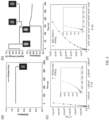
- FIG. 1(a) is a graphical representation illustrating chemical structures of an ECP-Black, an ECP-Magenta, and an ECP-Blue thin film, where R is 2-ethylhexyl.
- FIG. 1(b) is a diagram of cyclic voltammetry (CV) measurement results of the ECP-Black, ECP-Magenta, and ECP-Blue thin films.
- CV cyclic voltammetry
- a HOMO energy level of the ECP-Black was estimated to be - 4.8 eV by using an empirical formula (Eqn. (1)).
- the self-bleaching of the ECP-Black polymer could occur under V off due to an interface electron transfer (IET) according to a previous work ( Shin, H.; Seo, S.; Park, C.; Na, J.; Han, M.; Kim, E. Energy Saving Electrochromic Windows from Bistable Low-HOMO Level, Conjugated Polymers. Energy Environ. Sci. 2016, 9 (1), 117-122 ).
- IET interface electron transfer
- E HOMO ⁇ 4.8 + E ox ⁇ E 1 / 2 ferrocene eV
- E HOMO the HOMO energy level of the conjugated polymer
- E ox is an onset oxidation potential of the conjugated polymer obtained from the CV measurement result of the ECP-Black thin film, which is comparable to an E ox measured in a differential pulse voltammetry (DPV) measurement
- the E 1/2(ferrocene) is the half-wave potential of ferrocene.
- FIG. 2(a) shows a diagram illustrating an in-situ optical density (OD) measurement result of the ECP thin film at a pristine state; consistent with exemplary embodiments of the present disclosure.
- An inset in FIG. 2(a) shows a photograph of an exemplary pristine film.
- an optical memory of the pristine ECP-Black thin film was evaluated with recording the absorption change at ⁇ ⁇ max (640 nm) for 900 s under V off .
- the absorption of the pristine film remained unchanged, suggesting that the pristine thin-film did not undergo self-bleaching within the observation period. This observation does not follow the early report that conjugated polymers with HOMO levels higher than - 5.0 eV will undergo self-bleaching on the ITO substrate.
- 15 cycles of break-in processes was applied to the ECP-Black thin film by cycling from -0.2 V to 1.0 V at 40 mV/s.
- the ECP-Black thin film was first oxidized to its bleached state.
- the pre-oxidized thin film was then subjected to 1 V for 30 s and the potential was switched off from the 30 th to 150 th second.
- the absorption profile of the bleached ECP-Black thin film had little change, indicating that a self-coloring is absent.
- the ECP-Black thin film was reduced back to its colored (neutral) state by applying a reverse bias at -0.2 V for 30 s.
- FIG. 2(b) shows photographs of the exemplary ECP-Black film at different states.
- the ECP-Black thin film can be reversely switched from transmissive state to its original black-blue color state, suggesting that the polymer thin film does not decompose during the break-in process and the cycling test. Therefore, we propose that an activation of the self-bleaching behavior can be ascribed to a change of a structure of the ECP-Black thin film during oxidation-reduction (redox) processes.
- redox oxidation-reduction
- atomic-force microscopy (AFM) and electrochemical impedance spectroscopy (EIS) experiments may be conducted to probe the structural changes of the ECP-Black thin film after the break-in process.
- AFM atomic-force microscopy
- EIS electrochemical impedance spectroscopy
- looser topologies can be observed for ECP-black thin films after the break-in process.
- the loose morphologies can facilitate diffusions of solvated ions to compensate the positive charges generated on the polymer backbone during the self-bleaching process.
- PPy(DBS) polypyrrole (dodecylbenzenesulfonate)
- the volume changes of the first cycle may be between 60 - 100%, whereas only a 30 - 40% of volume change may be obtained in the following cycles. The differences of volume change indicate that the pristine compactness of the PPy(DBS) thin films cannot be recovered.
- FIGs. 2(c) - (d) are diagrams illustrating the EIS measurement results of the ECP-Black thin film: (c) at a pristine state and (d) after a break-in process and with 300s of a cathodic polarization, consistent with exemplary embodiments of the present disclosure.
- the EIS of the ECP-Black film before the break-in process was first measured, and the EIS was measured with a frequency from 1 Hz to 1 MHz.
- the break-in process was carried out, followed by a 300 s cathodic polarization potential (-0.2 V) that was applied to reset the ECP-Black thin film back to its color state.
- a 300 s cathodic polarization potential (-0.2 V) that was applied to reset the ECP-Black thin film back to its color state.
- the EIS of the broken-in thin film i.e., the thin film experienced with a break-in process was taken, as shown FIG. 2(d) .
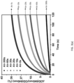
- FIG. 3(a) shows an exemplary short-term percentage change of the optical density after applied different periods of reverse bias (-0.2 V) in an ambient environment, consistent with exemplary embodiments of the present disclosure.
- the degree of self-bleaching within 120 s may decrease with an increase of the cathodic polarization time. The result matches the ESCR model.
- a electroosmotic process refers to a motion of ions induced by an applied potential across a porous material. Once the voltage is turned off, the degree of self-bleaching becomes lower, since it becomes more difficult for ions to penetrate into the thin film to compensate the positive charge generated in the self-bleaching process.
- FIG. 3(b) shows an exemplary short-term percentage change of the optical density after applied different periods of reverse bias (-0.2 V) under nitrogen flow with a 10 L/min flow rate, consistent with exemplary embodiments of the present disclosure.
- oxidant e.g. molecular oxygen in the air
- FIG. 3(b) shows an exemplary short-term percentage change of the optical density after applied different periods of reverse bias (-0.2 V) under nitrogen flow with a 10 L/min flow rate, consistent with exemplary embodiments of the present disclosure.
- a freeze pump treatment was applied to get rid of oxygen residues inside the electrolyte.
- a cuvette was sealed by a Teflon tape and parafilm inside the N 2 glove box. The spectral measurement was conducted under the N 2 protection. Results in FIG.
- the cathodic polarization may still play a role in controlling the degree of self-bleaching, which is similar to the results obtained under the ambient conditions.
- the degree of self-bleaching decreases when increasing the period of cathodic polarization.
- the existing of the oxidant were the dominant factor that caused the self-bleaching of the black-ECP thin film, then the self-bleaching would be observed for the pristine film before any electrochemical experiments (which cannot be observed in FIG. 2(a) ).
- the self-bleaching of the break-in ECP-Black thin films may be due to the spontaneous electron transfer from the ECP-Black thin film to the ITO electrode, instead of the effect of an oxidant.
- OTS Octadecyltrichlorosilane
- OFET organic field effect transistor
- the insulated nature of the OTS could be used to impede the spontaneous electron transfer associated with the self-bleaching of ECP thin film.
- the electrochemical processes of ECP thin films could be hampered at the same time.
- both roughness of the ITO and an immersion time of the ITO in the OTS solution are critical. For a rough unpolished ITO, it may take longer time ( ⁇ 15 hrs) to form a condensed self-assembled monolayer (SAM) layer. Kept under a 1 vol% OTS hexane solution for a short time (for example, 80 mins), ITO substrates may be partially modified by the OTS.
- ITO substrates was first washed by ultrasonic bath of ethanol, acetone, ethanol for about 10 mins each. Then the washed ITO substrates was dried by nitrogen blowing. Next, conducting sides of the ITO substrates was treated for about 20 mins in a UV-ozone chamber. Then the ITO was partially covered by the OTS monolayer (POTS) after immersing in a 1 vol% OTS hexane solution for about 80 mins.
- POTS OTS monolayer
- FIG. 4(a) is a diagram illustrating cyclic voltammetry results of 0.1M Ferrocene in 0.1 M TBAPF 6 propylene carbonate (PC) using a POTS-ITO, a condensed OTS (COTS)-ITO, and an ITO as working electrodes, consistent with exemplary embodiments of the present disclosure.
- the voltammogram of ferrocene shows a lower peak current density, and a larger distance between cathodic and anodic peaks, as compared to the bare ITO.
- a more condensed OTS layer can be formed on an ITO, which is indicated by the extremely small current from the CV of ferrocene, as shown in FIG.
- the distinct difference between the CV signals of ferrocene may demonstrate that the ITO is partially covered by the OTS at which electron transfer is interfered, but could proceed with the aid of an external potential.
- the coverage of the OTS on the ITO may be between 10% to 40%, estimated from the anodic peak current of cyclic voltammetry results.
- FIG. 4(b) is a graphical representation illustrating exemplary AFM images of the ITO and POTS-ITO; and FIG. 4(c) is exemplary contact angle images of a bare ITO, a UV-ozone treated ITO and a POTS-ITO, consistent with exemplary embodiments of the present disclosure.
- the contact angle measurements in some embodiments, 5 ⁇ L of deionized water was first titrated on the top of each substrate, and images then was taken immediately. The substrate was cleaned by a UV-ozone before the OTS modification. The surface wettability of the bare ITO, UV- ozone cleaned ITO, and partially OTS modified ITO (POTS-ITO) can be determined by their contact angles, respectively. In some embodiments, the average contact angle values may be obtained from measurements at four different positions (shown in Table 2). Table 2 Bare ITO UV-Ozone-ITO POTS-ITO 79.87 ⁇ 5.91 80.02 ⁇ 6.30 49.12 ⁇ 2.43 49.04 ⁇ 3.27 115.95 ⁇ 2.09 115.46 ⁇ 1.63
- the ITO surface may become more hydrophilic with a small contact angle.
- the hydrophobicity of the ITO surface increases after the OTS modification, suggested by a larger value of the contact angle ⁇ 116°.
- the increase of the contact angle compared to that of the UV-zone treated ITO ( ⁇ 49°) suggests the formation of OTS layer on the ITO surface.
- the average R q increases slightly from 2.93 to 3.38 nm which may suggest a SAM layer has been formed on most of the surfaces.
- the degree of self-bleaching was measured for ECP-Black thin films on both ITO and POTS-ITO. From curves of the first derivative of the OD (640 nm) as a function of time, the change of the OD (640 nm) was negligible after ⁇ 500 s, which is indicated by a small value of the decay rate (dOD/dt). Thus, in some embodiments, 900 s is sufficient and can be selected as a time period for monitoring the degree of a self-bleaching behavior.
- FIGs. 5(a) - (c) are diagrams illustrating long-term percentage changes of the OD of an ECP-Black, an ECP-Magenta, and an ECP-Blue thin film, consistent with exemplary embodiments of the present disclosure.
- FIG. 5(a) shows a long-term percentage change of the OD of an ECP-Black thin film on a bare ITO after a 60 s cathodic polarization, and on a POTS-ITO after 60 s and 300 s cathodic polarization.
- the degree of self-bleaching was observed to decrease from 27.6% ⁇ 4.6% to 15.5 ⁇ 2.98% after using the POTS-ITO and 60 s cathodic polarization.
- the average and standard deviation are calculated based on three individual experiments.
- This decrease in self-bleaching is because that the spontaneous electron transfer is disturbed by the insulated POTS layer.
- the degree of self-bleaching was further reduced to 7.6% ⁇ 1.4%. This phenomenon may also support that the self-bleaching behaviors of the ECP-Black thin film are primarily caused by the IET at the organic/ITO interfaces.
- an ECP- Magenta, and an ECP-Blue thin film was selected to measure the optical memory after break-in on both bare ITO and POTS-ITO, and exemplary measurement results are presented in FIGs. 5(b) and (c) respectively.
- Both the ECP-Magenta and ECP-Blue polymer films showed self-bleaching behaviors, because of their high HOMO levels which are calculated to be - 4.79 eV and - 4.95 eV, respectively (shown in FIG. 1 ).
- the POTS modification and cathodic polarization may be able to suppress the self-bleaching behaviors of ECP.
- spectroelectrochemical behaviors and electrochromic switching of the ECP-Black thin film on the POTS-ITO was also studied. Comparing the ECP-Black thin film on a bare ITO and a POTS-ITO, in some embodiments, no obvious difference was identified. Since the ITO surface is partially covered by the OTS, electrochemical oxidation/reduction can still progress when driven by an external potential. From an energy point of view, coloration efficiency (CE) measurements can be carried out for the broken-in thin films of the ECP-Black on both substrates. Coloration efficiency can be defined as a change in optical density per unit of inserted charge. FIG.
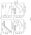
- FIG. 6(a) is a diagram illustrating a coloration efficiency of exemplary ECP-Black thin films on a bare ITO and a POTS-ITO, consistent with exemplary embodiments of the present disclosure.
- the CE of the bleached processes can be calculated from a slope of a curve plotted by ⁇ OD vs. ejected charge density. Compared to the slope obtained from the ECP-Black on the bare ITO, the CE of the ECP-Black on the POTS-ITO is more inclined at the beginning, but starts to gradually decrease till the end, as shown in FIG. 6(a) .
- the initial larger values of the CE may be due to a better contact between the polymer thin film and the ITO electrode, so the electron transfer driven by externally applied voltage is more efficient at the beginning.
- due to the existing of insulated features of POTS modified surfaces it may require more energy to completely oxidize the whole ECP-Black thin film.
- a cycling stability of the ECP-Black on the POTS-ITO was tested by cyclic voltammetry (CV) and double potential step chronoamperometric (DPSC).
- the CV cycling test can access the adhesion of the ECP-Black thin film on the substrate by monitoring the development of the voltammogram and peak current density of each cycle.
- DPSC cycling experiments can provide in-situ transmittance change at an on-off switching mode. However, the transmittance measurement is based on one spot where the light penetrates through, so the result may not represent the conditions of the entire film. Therefore, we can combine these two methods to evaluate the effect of POTS in term of the cycling stability.
- FIG. 6 (b) is a diagram illustrating anodically peak currents of the exemplary ECP-Black thin films on a POTS-ITO and a bare ITO versus number of cycles; and FIGs. 6(c) - (d) are diagrams illustrating selected cycling voltammetry of exemplary ECP-Black thin films on a bare ITO and a POTS-ITO, consistent with exemplary embodiments of the present disclosure.
- the CV cycling experiments were scanned between -0.2 V to 1.0 V at a scan rate of 40 mV/s.
- the development of the anodic peak current density (I pa ) of CV is summarized in FIG. 6(b) .
- the voltammogram of the initial cycle, 4 th cycle, and the last cycle were shown in FIGs. 6(c) and 6(d) for the ECP-Black on the POTS-ITO and the bare ITO, respectively.
- the I pa of the first scan (dash line) was excluded due to a first scan effect as shown in FIGs. 6(c) and 6(d).
- the I pa of the CV decreased rapidly, and shapes of the CV changed dramatically with more and more cycles, indicating a delamination of the ECP-Black from the bare ITO.
- the electrochromic thin films on the ITO may be expanded/contracted due to incorporations and extractions of solvated ions.
- the hydrophilic surface of the ITO may not provide enough adhesion to hydrophobic conjugated polymer thin films to overcome the volume change. It may lead to the delamination of the thin film, indicated by a 28% decrease (from 2 nd cycle to 150 th cycle) of the value of I pa .
- the position of anodic peak slightly moved towards higher potential while the oxidation onset was comparable, indicating that electron transfer is partially impeded.
- the I pa for the ECP-Black on the POTS-ITO increased slightly from the 1 st to 4 th cycle as the thin film became looser for solvated ions to permeate into, and more materials could get involved in the reaction.
- the I pa decreased 10% from 4 th cycle to 200 th cycle (shown in FIG. 6(b) ).
- the overall shape of CV only changed slightly for the 200 cycles, indicating that the ECP-Black on the POTS-ITO can maintain its adhesion via the hydrophobic interaction (FIG. 6(d)), thus the cycling stability is improved.
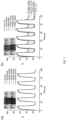
- FIGs. 7(a) - (b) are diagrams illustrating transmittance at 640 nm of exemplary ECP-Black thin films on a POTS-ITO and a Bare ITO under DPSC experiments, consistent with exemplary embodiments of the present disclosure.
- the potential was switching between -0.2 V and 1.0 V with a 10 s interval.
- the optical contrast of ECP-Black thin film on POTS-ITO was maintained up to 2300 cycles with losing only 5% of its original contrast. After ⁇ 4300 cycles, most part of the ECP-Black thin film could remain a good adhesion on the POTS-ITO, as shown in FIG. 7(a) .
- FIG. 7(a) is a photography of the thin film after 4300 cycles.
- losses of optical contrast can be observed for the ECP-Black thin film on a bare ITO at about 600 cycles, and increased to about 35 % loss of its original contrast after about 1800 cycles, indicating the delamination of the thin film.
- the ECP-Black thin film delaminated from the bare ITO, and was not capable of being fully reduced back to black-blue color as shown in the photograph in FIG. 7(b) .
- electrochemistry related experiments may be performed using BioLogic SP-150.
- a UV-vis spectrum and an optical memory which is a kinetic measurement of absorption at certain wavelength may be obtained from Agilent Cary 5000 UV-Vis-NIR spectrophotometer.
- AFM images may be taken by using the Veeco dimension 3100.
- Contact Angle measurements may be carried out by using Ramé-Hart Model 790.
- CV experiments may be carried out by using a conventional three-electrode system.
- Working electrodes may be ITO coated by polymer thin films; the pseudoreference electrode is an Ag wire coated by AgCl; the counter electrode may be a platinum wire; the electrolyte may be 0.2 M TBAPF 6 in PC.
- the thin film of polymer may be made by spin-coating ⁇ 0.1 ml of 40 mg/ml solution on top of the ITO with a 1500 rpm/s spin rate to form a film with ⁇ 375 nm thick which shows the highest optical contrast.
- the voltage may be scanned from -0.2 V to 1.0 V at a 40 mV/s scan rate for the ECP-Black and ECP-Magenta, and from -0.2V to 1.3V at a 40 mV/s scan rate for the ECP-Blue. Same set-up and parameters may be also used for the CV cycling stability test.
- the anodic peak current density in the voltammogram may be used to indicate the cycling stability of the polymer thin film.
- 15 cycles of break-in may be used before the characterizations of the polymer thin films unless otherwise mentioned.
- DPV measurements may be done by using a platinum bottom as a working electrode.
- a thin polymer layer may be coated on top of the platinum bottom by drop casting the 3 - 5 mg/ml solution. All other set-ups may be the same as CV experiments.
- a pulse height of 20 mV, a pulse width of 50 ms, a step height of 1.0 mV, and a step time of 100 ms may be used.
- the potential range for the experiment may be set between -0.2 and 1.0 V.
- an optical memory may be tested by measuring ⁇ OD (640 nm) of the thin films under open circuit conditions.
- the broken-in thin film may be oxidized by applying 1.0 V for 30 s for the ECP-Black and ECP-Magenta, and 1.3 V for 30s for the ECP-Blue.
- the optical memory at bleached state may be recorded for 2 mins.
- a - 0.2 V cathodic potential may be applied for certain time (5 s, 10 s, 20 s, 30 s, 60 s, 300 s).
- the potential may be switched to voltage off and the optical memories at color state may be recorded for 120 s for short-term measurement, and 900 s for long-term measurement.
- N 2 may be pre-purged into the chamber of the Cary 5000 for 30 mins at 10 L/mins before the experiments, and may be continuously supplied in the rest of the experiments.
- AFM images may be obtained in a tapping mode at a 0.5 Hz scan rate.
- the average R q may be calculated based on three different images.
- a fully or partially modified transparent conductive oxide substrate for example, partially OTS modified ITO
- cathodic polarization to probe and study the self-bleaching behaviors of the ECP-Black thin films.
- a method to mitigate the self-bleaching problems of ECP thin films with these two approaches.
- surface modification could increasing the adhesion between EC polymer and the conductive surface.
- the POTS layer can turn the ITO surface to hydrophobic which provides stronger adhesion to the conjugated polymer thin films. As a result, the cycling stability of the ECP-Black thin film can be enhanced.
- a SAM layer can also be investigated, since it can induce an interface dipole to increase a work function of the ITO, so that the electron transfer at the ITO/ECP interfaces can be completely prevented under V off . Also, the adhesion of thin film can be improved on the ITO surface to enhance the cycling stability.
- This disclosure could provide instructions on an automation control of electrochromic windows for improving energy saving. Knowing the factors that can control the self-bleaching behaviors, the colored state of the electrochromic windows can be maintained by refreshing cathodic bias at a low frequency and with a minimum energy consumption. This disclosure provides more insight into the self-bleaching behaviors of the ECP polymers and brings the ECP a step forward to practical applications.
Landscapes
- Physics & Mathematics (AREA)
- Nonlinear Science (AREA)
- Chemical & Material Sciences (AREA)
- Optics & Photonics (AREA)
- General Physics & Mathematics (AREA)
- Organic Chemistry (AREA)
- Materials Engineering (AREA)
- Engineering & Computer Science (AREA)
- Crystallography & Structural Chemistry (AREA)
- Mathematical Physics (AREA)
- Health & Medical Sciences (AREA)
- Chemical Kinetics & Catalysis (AREA)
- Medicinal Chemistry (AREA)
- Polymers & Plastics (AREA)
- Electrochromic Elements, Electrophoresis, Or Variable Reflection Or Absorption Elements (AREA)
Claims (9)
- Dispositif électrochrome, ECD, l'ECD comprenant :un substrat d'oxyde d'indium et d'étain, ITO, recouvert partiellement d'octadécyltrichlorosilane, OTS, substrat POTS-ITO, dans lequel le substrat POTS-ITO est un substrat ITO comprenant une couverture OTS entre environ 10 % et environ 40 % ; etun film polymère électrochimique, ECP, sur le substrat POTS-ITO, dans lequel le substrat POTS-ITO est obtenu par un procédé comprenant l'immersion d'un substrat ITO dans une solution OTS-hexane pendant environ 80 minutes, dans lequel la concentrationen OTS dans la solution OTS-hexane est de 1 % en volume ;moyennant quoi le POTS-ITO élimine le comportement d'auto-blanchiment de l'ECP.
- Dispositif électrochrome selon la revendication 1, dans lequel le procédé, pour obtenir le substrat POTS-ITO, comprend en outre :le lavage du substrat ITO dans un bain ultrasonore d'éthanol, d'acétone et d'éthanol pendant environ 10 minutes chacun ;le séchage du substrat ITO ; etle traitement d'un côté conducteur du substrat ITO dans une chambre UV-ozone avant l'immersion du substrat ITO dans la solution OTS-hexane.
- Dispositif électrochrome selon l'une quelconque des revendications 1 à 2, dans lequel le film ECP est en outre traité en appliquant une polarisation cathodique ; et facultativement, comprenant une ou plusieurs des caractéristiques suivantes dans lesquelles :(i) la polarisation cathodique est appliquée pendant environ 60 secondes à environ 300 secondes ;(ii) l'OTS forme une monocouche auto-assemblée sur le substrat ITO ;(iii) l'épaisseur de la couche OTS est d'environ 2 à 4 nm ;(iv) le substrat ITO présente des angles de contact d'au moins 100° ;(v) le substrat POTS-ITO a une hydrophobicité plus grande que le substrat ITO ; et(vi) le substrat POTS-ITO présente une densité de courant de crête plus basse et une distance plus grande entre des crêtes cathodique et anodique que le substrat ITO lors d'une mesure de voltampérométrie cyclique.
- Dispositif électrochrome selon l'une quelconque des revendications 1 à 3, dans lequel le film ECP est sélectionné parmi un groupe constitué par un film noir ECP, un film magenta ECP et un film bleu ECP ; ou,dans lequel le film ECP comprend un ECP sélectionné parmi le poly-3,4-éthylènedioxythiophène (PEDOT), le poly-2,2'-bithiophène, le polypyrrole, la polyaniline (PANI), le polythiophène, le polyisothianaphtène, le poly(oaminophénol), la polypyridine, le polyindole, le polycarbazole, la polyquinone, l'octacyanophtalocyanine, le viologène, l'anthraquinone, la phénocyazine et des combinaisons de ceux-ci ; ou,dans lequel le film ECP comprend un ECP sélectionné parmi

 dans lequel R est alkyle en C1-C30, chacun de x, y et n est indépendamment un nombre entier supérieur à 0 ; etfacultativement, dans lequel R est le 2-éthylhexyle, chacun de x et y est indépendamment un nombre entier de 1 à 12, et n est un nombre entier de 1 à 200 ; etde préférence, dans lequel l'épaisseur du film ECP est d'environ 200 nm à environ 500 nm.
 - Dispositif électrochrome selon l'une quelconque des revendications 1 à 4, et comprenant une ou plusieurs des caractéristiques suivantes dans lequel :(i) le film ECP est capable de maintenir un état coloré pendant au moins 300 secondes ou au moins 600 secondes ;(ii) le film ECP sur le substrat POTS-ITO a une stabilité de cycle qui est plus grande que celle du film ECP sur le substrat ITO ;(iii) le film ECP a une stabilité de cycle de maintien d'au moins 95 % du contraste de couleurs après 2000 cycles redox ou plus ;(iv) l'ECD est une fenêtre intelligente ou un système d'affichage.
- Procédé pour préparer un dispositif électrochrome, ECD, comprenant la formation d'un film polymère électrochrome sur un substrat d'oxyde conducteur transparent modifié dans lequel le substrat d'oxyde conducteur transparent modifié est un substrat d'oxyde d'indium et d'étain, ITO, recouvert partiellement d'octadécyltrichlorosilane, OTS, substrat POTS-ITO, dans lequel le substrat POTS-ITO est un substrat ITO comprenant une couverture OTS entre environ 10 % et environ 40 %, dans lequel l'obtention du substrat POTS-ITO comprend :
l'immersion du substrat ITO dans une solution OTS-hexane pendant 80 minutes et dans lequel la concentration en OTS dans la solution OTS-hexane est de 1 % en volume. - Procédé pour préparer le dispositif électrochrome selon la revendication 6, comprenant en outre l'application d'une polarisation cathodique pendant au moins environ 60 secondes.
- Procédé pour supprimer un comportement d'auto-blanchiment d'un film polymère électrochimique, ECP, comprenant :l'obtention d'un substrat d'oxyde conducteur transparent modifié, dans lequel le substrat d'oxyde conducteur transparent modifié est un substrat d'oxyde d'indium et d'étain, ITO, recouvert partiellement d'octadécyltrichlorosilane, OTS, substrat POTS-ITO, dans lequel le POTS-ITO est un substrat ITO comprenant une couverture OTS entre 10 % et environ 40 % ; etla formation du film ECP sur le substrat POTS-ITO ; etl'application d'une polarisation cathodique, dans lequel l'obtention du substrat POTS-ITO comprend :l'immersion du substrat ITO dans une solution OTS-hexane pendant environ 80 minutes et,dans lequel la concentration en OTS dans la solution OTS-hexane est d'environ 1 % en volume.
- Procédé selon la revendication 6 ou 8, comprenant en outre une ou plusieurs des caractéristiques suivantes :(i) nettoyage du substrat ITO avant l'immersion du substrat ITO dans la solution OTS-hexane ; et facultativement, dans lequel le nettoyage du substrat ITO comprend :le lavage du substrat ITO dans un bain ultrasonore d'éthanol, d'acétone et d'éthanol pendant 10 minutes chacun ;le séchage du substrat ITO ; etle traitement d'un côté conducteur du substrat ITO dans une chambre UV-ozone ; et de préférence,dans lequel le matériau de modification forme une monocouche auto-assemblée sur le substrat ;(ii) dans lequel la polarisation cathodique est appliquée pendant environ 60 secondes à environ 300 secondes ;(iii) dans lequel le substrat modifié a une hydrophobicité plus grande que le substrat non modifié ;(iv) dans lequel le film ECP est sélectionné parmi un groupe constitué par un film noir ECP, un film magenta ECP et un film bleu ECP ; ou,dans lequel le film ECP comprend un ECP sélectionné parmi le poly-3,4-éthylènedioxythiophène (PEDOT), le poly-2,2'-bithiophène, le polypyrrole, la polyaniline (PANI), le polythiophène, le polyisothianaphtène, le poly(oaminophénol), la polypyridine, le polyindole, le polycarbazole, la polyquinone, l'octacyanophtalocyanine, le viologène, l'anthraquinone, la phénocyazine et des combinaisons de ceux-ci ; ou, dans lequel le film ECP comprend un ECP sélectionné parmi :

 dans lequel R est alkyle en C1-C30, chacun de x, y et n est indépendamment un nombre entier supérieur à 0 ; etfacultativement, dans lequel R est le 2-éthylhexyle, chacun de x et y est indépendamment un nombre entier de 1 à 12, et n est un nombre entier de 1 à 200 ;(v) dans lequel l'épaisseur du film ECP est d'environ 200 nm à environ 500 nm ;(vi) dans lequel la stabilité de cycle du film ECP sur le substrat modifié est plus grande que celle du film ECP sur le substrat non modifié ;(vii) dans lequel le substrat modifié présente une densité de courant de crête plus petite et une distance plus grande entre des crêtes cathodique et anodique que le substrat non modifié lors d'une mesure de voltampérométrie cyclique ; et(viii) dans lequel le film ECP est capable de maintenir un état coloré pendant au moins 300 secondes ou au moins 600 secondes ; et de préférence, dans lequel le film ECP a une stabilité de cycle de maintien d'au moins 95 % du contraste de couleurs après 2000 cycles redox ou plus.
Applications Claiming Priority (2)
| Application Number | Priority Date | Filing Date | Title |
|---|---|---|---|
| US201762532699P | 2017-07-14 | 2017-07-14 | |
| PCT/US2018/041679 WO2019014369A1 (fr) | 2017-07-14 | 2018-07-11 | Films minces polymères électrochromiques ayant un comportement d'auto-blanchiment réduit et une stabilité de cycle améliorée |
Publications (3)
| Publication Number | Publication Date |
|---|---|
| EP3652111A1 EP3652111A1 (fr) | 2020-05-20 |
| EP3652111A4 EP3652111A4 (fr) | 2020-12-09 |
| EP3652111B1 true EP3652111B1 (fr) | 2023-02-22 |
Family
ID=65002438
Family Applications (1)
| Application Number | Title | Priority Date | Filing Date |
|---|---|---|---|
| EP18832949.4A Active EP3652111B1 (fr) | 2017-07-14 | 2018-07-11 | Films minces polymères électrochromiques ayant un comportement d'auto-blanchiment réduit et une stabilité de cycle améliorée |
Country Status (4)
| Country | Link |
|---|---|
| US (1) | US10921674B2 (fr) |
| EP (1) | EP3652111B1 (fr) |
| CN (1) | CN110809560B (fr) |
| WO (1) | WO2019014369A1 (fr) |
Families Citing this family (10)
| Publication number | Priority date | Publication date | Assignee | Title |
|---|---|---|---|---|
| CN110684521B (zh) * | 2019-08-28 | 2023-02-28 | 合肥工业大学 | 一种共价键合三氧化钨纳米线/聚噻吩电致变色材料及其制备方法 |
| US11773213B2 (en) * | 2020-07-13 | 2023-10-03 | Ambilight Inc. | Thermally stable and solvent-resistant conductive polymer composites |
| KR20220036713A (ko) * | 2020-09-16 | 2022-03-23 | 현대자동차주식회사 | 색상 가변 플라스틱 |
| KR102829345B1 (ko) | 2020-11-03 | 2025-07-02 | 현대자동차주식회사 | 색상 가변 플라스틱 |
| CN114563895A (zh) * | 2022-03-10 | 2022-05-31 | 四川大学 | 一种多孔导电聚合物基电致变色薄膜及其制备方法 |
| WO2023172066A1 (fr) * | 2022-03-11 | 2023-09-14 | 에스케이씨 주식회사 | Dispositif électrochromique et son procédé de fabrication |
| KR102713455B1 (ko) * | 2022-03-11 | 2024-10-04 | 에스케이씨 주식회사 | 전기변색소자 및 이의 제조방법 |
| KR102713454B1 (ko) * | 2022-03-11 | 2024-10-04 | 에스케이씨 주식회사 | 전기변색소자 및 이의 제조방법 |
| JP2026003961A (ja) * | 2024-06-25 | 2026-01-14 | Jfeスチール株式会社 | 積層体、ペロブスカイト太陽電池、積層体の製造方法およびペロブスカイト太陽電池の製造方法 |
| CN119371697A (zh) * | 2024-12-30 | 2025-01-28 | 牛津大学(苏州)科技有限公司 | 电致变色聚合物膜、制备方法、含其电致变色器件及应用 |
Family Cites Families (7)
| Publication number | Priority date | Publication date | Assignee | Title |
|---|---|---|---|---|
| US4973391A (en) * | 1988-08-30 | 1990-11-27 | Osaka Gas Company, Ltd. | Composite polymers of polyaniline with metal phthalocyanine and polyaniline with organic sulfonic acid and nafion |
| US5086351A (en) * | 1989-07-13 | 1992-02-04 | M&T Chemicals, Inc. | Electrochromic elements, materials for use in such element, processes for making such elements and such materials and use of such element in an electrochromic glass device |
| EP1854160B1 (fr) * | 2005-02-10 | 2017-06-21 | Yeda Research And Development Co., Ltd. | Structures redox actives et dispositifs utilisant celles-ci |
| US8593714B2 (en) * | 2008-05-19 | 2013-11-26 | Ajjer, Llc | Composite electrode and electrolytes comprising nanoparticles and resulting devices |
| JP2009145461A (ja) * | 2007-12-12 | 2009-07-02 | Konica Minolta Holdings Inc | 電気化学表示素子及びその製造方法 |
| TW201009062A (en) * | 2008-05-07 | 2010-03-01 | Nissan Chemical Ind Ltd | Electrochromic material |
| US10115917B2 (en) | 2015-05-19 | 2018-10-30 | Northwestern University | Dopant-free polymeric hole-transporting materials for perovskite solar cell |
-
2018
- 2018-07-11 CN CN201880043215.8A patent/CN110809560B/zh active Active
- 2018-07-11 WO PCT/US2018/041679 patent/WO2019014369A1/fr not_active Ceased
- 2018-07-11 EP EP18832949.4A patent/EP3652111B1/fr active Active
- 2018-07-11 US US16/032,980 patent/US10921674B2/en active Active
Non-Patent Citations (2)
| Title |
|---|
| CHOI YOUNGSIK ET AL: "Structural Effect on Formation of Alkylsilane Self-Assembled Monolayers on Indium Tin Oxide Surface", MOLECULAR CRYSTALS AND LIQUID CRYSTALS, vol. 492, no. 1, 9 October 2008 (2008-10-09), UK, pages 165/ 529! - 171/ 535!, XP055846631, ISSN: 1542-1406, DOI: 10.1080/15421400802330556 * |
| MARKOVICH INNA ET AL: "Preparation and characterization of octadecylsilane monolayers on indium-tin oxide (ITO) surfaces", JOURNAL OF ELECTROANALYTICAL CHEMISTRY, vol. 500, no. 1-2, 1 March 2001 (2001-03-01), AMSTERDAM, NL, pages 453 - 460, XP055846640, ISSN: 1572-6657, DOI: 10.1016/S0022-0728(00)00458-7 * |
Also Published As
| Publication number | Publication date |
|---|---|
| WO2019014369A1 (fr) | 2019-01-17 |
| CN110809560B (zh) | 2021-11-09 |
| CN110809560A (zh) | 2020-02-18 |
| EP3652111A1 (fr) | 2020-05-20 |
| US20190086757A1 (en) | 2019-03-21 |
| EP3652111A4 (fr) | 2020-12-09 |
| US10921674B2 (en) | 2021-02-16 |
Similar Documents
| Publication | Publication Date | Title |
|---|---|---|
| US10921674B2 (en) | Electrochromic polymer thin films having reduced self-bleaching behavior and enhanced cycling stability | |
| CA2849307C (fr) | Appareil electrochromique transparent et flexible et methode de preparation de celui-ci | |
| US11609471B2 (en) | Minimally color changing n-type ion storage layers, electrochromic devices made therewith, and related methods | |
| Ling et al. | One-pot sequential electrochemical deposition of multilayer poly (3, 4-ethylenedioxythiophene): poly (4-styrenesulfonic acid)/tungsten trioxide hybrid films and their enhanced electrochromic properties | |
| Poverenov et al. | Major effect of electropolymerization solvent on morphology and electrochromic properties of PEDOT films | |
| JP3009725B2 (ja) | エレクトロクロミック素子、この素子に使用する物質、この素子の製造方法及びエレクトロクロミックガラス装置におけるこの素子の使用 | |
| US6266177B1 (en) | Electrochromic devices | |
| US20170031224A1 (en) | Methods for producing electrochromic films by low temperature condensation of polyoxometalates | |
| EP2965148A1 (fr) | Dispositif electrochrome a quatre ou trois couches | |
| Najafi-Ashtiani et al. | A dual electrochromic film based on nanocomposite of copolymer and WO3 nanoparticles: Enhanced electrochromic coloration efficiency and switching response | |
| He et al. | Self-bleaching behaviors in black-to-transmissive electrochromic polymer thin films | |
| Yoo et al. | High contrast ratio and fast switching polymeric electrochromic films based on water-dispersible polyaniline-poly (4-styrenesulfonate) nanoparticles | |
| Lin et al. | Electrochromic properties of nano-composite nickel oxide film | |
| CN107479293A (zh) | 一种可见红外分区可控的电致变色器件及其制备方法 | |
| Döbbelin et al. | Innovative materials and applications based on poly (3, 4-ethylenedioxythiophene) and ionic liquids | |
| León-Silva et al. | Effect of modified ITO substrate on electrochromic properties of polyaniline films | |
| JP2017026750A (ja) | エレクトロクロミック素子、調光眼鏡及びエレクトロクロミック素子の製造方法 | |
| Vasantha et al. | Effect of hydroxypropyl-β-cyclodextrin on the electrochemical oxidation and polymerization of 3, 4-ethylenedioxythiophene | |
| Baray-Calderón et al. | Enhanced performance of poly (3-hexylthiophene)-based electrochromic devices by adding a mesoporous TiO2 layer | |
| CN110501852B (zh) | 一种基于高浓水系电解质的电致变色器件及其制备方法 | |
| US10377943B2 (en) | Black-to-transmissive electrochromic device | |
| KR102795480B1 (ko) | 전기변색 장치의 투명 전도성 산화물 전극을 위한 보호용 층 | |
| US12228836B2 (en) | Method of manufacturing thin film electrode for electrochromic device and electrochromic device including the same | |
| CN102918454B (zh) | 制造一种电致变色物品的方法 | |
| KR20210051342A (ko) | 전기변색소자 |
Legal Events
| Date | Code | Title | Description |
|---|---|---|---|
| STAA | Information on the status of an ep patent application or granted ep patent |
Free format text: STATUS: THE INTERNATIONAL PUBLICATION HAS BEEN MADE |
|
| PUAI | Public reference made under article 153(3) epc to a published international application that has entered the european phase |
Free format text: ORIGINAL CODE: 0009012 |
|
| STAA | Information on the status of an ep patent application or granted ep patent |
Free format text: STATUS: REQUEST FOR EXAMINATION WAS MADE |
|
| 17P | Request for examination filed |
Effective date: 20191125 |
|
| AK | Designated contracting states |
Kind code of ref document: A1 Designated state(s): AL AT BE BG CH CY CZ DE DK EE ES FI FR GB GR HR HU IE IS IT LI LT LU LV MC MK MT NL NO PL PT RO RS SE SI SK SM TR |
|
| AX | Request for extension of the european patent |
Extension state: BA ME |
|
| DAV | Request for validation of the european patent (deleted) | ||
| DAX | Request for extension of the european patent (deleted) | ||
| REG | Reference to a national code |
Ref country code: DE Ref legal event code: R079 Ref document number: 602018046498 Country of ref document: DE Free format text: PREVIOUS MAIN CLASS: C01G0015000000 Ipc: C09K0009020000 |
|
| A4 | Supplementary search report drawn up and despatched |
Effective date: 20201105 |
|
| RIC1 | Information provided on ipc code assigned before grant |
Ipc: G02F 1/155 20060101ALI20201030BHEP Ipc: C09K 9/02 20060101AFI20201030BHEP Ipc: G02F 1/1516 20190101ALI20201030BHEP |
|
| STAA | Information on the status of an ep patent application or granted ep patent |
Free format text: STATUS: EXAMINATION IS IN PROGRESS |
|
| 17Q | First examination report despatched |
Effective date: 20211012 |
|
| GRAP | Despatch of communication of intention to grant a patent |
Free format text: ORIGINAL CODE: EPIDOSNIGR1 |
|
| STAA | Information on the status of an ep patent application or granted ep patent |
Free format text: STATUS: GRANT OF PATENT IS INTENDED |
|
| INTG | Intention to grant announced |
Effective date: 20220830 |
|
| GRAS | Grant fee paid |
Free format text: ORIGINAL CODE: EPIDOSNIGR3 |
|
| GRAA | (expected) grant |
Free format text: ORIGINAL CODE: 0009210 |
|
| STAA | Information on the status of an ep patent application or granted ep patent |
Free format text: STATUS: THE PATENT HAS BEEN GRANTED |
|
| AK | Designated contracting states |
Kind code of ref document: B1 Designated state(s): AL AT BE BG CH CY CZ DE DK EE ES FI FR GB GR HR HU IE IS IT LI LT LU LV MC MK MT NL NO PL PT RO RS SE SI SK SM TR |
|
| REG | Reference to a national code |
Ref country code: GB Ref legal event code: FG4D |
|
| REG | Reference to a national code |
Ref country code: CH Ref legal event code: EP |
|
| REG | Reference to a national code |
Ref country code: AT Ref legal event code: REF Ref document number: 1549533 Country of ref document: AT Kind code of ref document: T Effective date: 20230315 Ref country code: IE Ref legal event code: FG4D |
|
| REG | Reference to a national code |
Ref country code: DE Ref legal event code: R096 Ref document number: 602018046498 Country of ref document: DE |
|
| REG | Reference to a national code |
Ref country code: LT Ref legal event code: MG9D |
|
| REG | Reference to a national code |
Ref country code: NL Ref legal event code: MP Effective date: 20230222 |
|
| REG | Reference to a national code |
Ref country code: AT Ref legal event code: MK05 Ref document number: 1549533 Country of ref document: AT Kind code of ref document: T Effective date: 20230222 |
|
| PG25 | Lapsed in a contracting state [announced via postgrant information from national office to epo] |
Ref country code: RS Free format text: LAPSE BECAUSE OF FAILURE TO SUBMIT A TRANSLATION OF THE DESCRIPTION OR TO PAY THE FEE WITHIN THE PRESCRIBED TIME-LIMIT Effective date: 20230222 Ref country code: PT Free format text: LAPSE BECAUSE OF FAILURE TO SUBMIT A TRANSLATION OF THE DESCRIPTION OR TO PAY THE FEE WITHIN THE PRESCRIBED TIME-LIMIT Effective date: 20230622 Ref country code: NO Free format text: LAPSE BECAUSE OF FAILURE TO SUBMIT A TRANSLATION OF THE DESCRIPTION OR TO PAY THE FEE WITHIN THE PRESCRIBED TIME-LIMIT Effective date: 20230522 Ref country code: NL Free format text: LAPSE BECAUSE OF FAILURE TO SUBMIT A TRANSLATION OF THE DESCRIPTION OR TO PAY THE FEE WITHIN THE PRESCRIBED TIME-LIMIT Effective date: 20230222 Ref country code: LV Free format text: LAPSE BECAUSE OF FAILURE TO SUBMIT A TRANSLATION OF THE DESCRIPTION OR TO PAY THE FEE WITHIN THE PRESCRIBED TIME-LIMIT Effective date: 20230222 Ref country code: LT Free format text: LAPSE BECAUSE OF FAILURE TO SUBMIT A TRANSLATION OF THE DESCRIPTION OR TO PAY THE FEE WITHIN THE PRESCRIBED TIME-LIMIT Effective date: 20230222 Ref country code: HR Free format text: LAPSE BECAUSE OF FAILURE TO SUBMIT A TRANSLATION OF THE DESCRIPTION OR TO PAY THE FEE WITHIN THE PRESCRIBED TIME-LIMIT Effective date: 20230222 Ref country code: ES Free format text: LAPSE BECAUSE OF FAILURE TO SUBMIT A TRANSLATION OF THE DESCRIPTION OR TO PAY THE FEE WITHIN THE PRESCRIBED TIME-LIMIT Effective date: 20230222 Ref country code: AT Free format text: LAPSE BECAUSE OF FAILURE TO SUBMIT A TRANSLATION OF THE DESCRIPTION OR TO PAY THE FEE WITHIN THE PRESCRIBED TIME-LIMIT Effective date: 20230222 |
|
| PG25 | Lapsed in a contracting state [announced via postgrant information from national office to epo] |
Ref country code: SE Free format text: LAPSE BECAUSE OF FAILURE TO SUBMIT A TRANSLATION OF THE DESCRIPTION OR TO PAY THE FEE WITHIN THE PRESCRIBED TIME-LIMIT Effective date: 20230222 Ref country code: PL Free format text: LAPSE BECAUSE OF FAILURE TO SUBMIT A TRANSLATION OF THE DESCRIPTION OR TO PAY THE FEE WITHIN THE PRESCRIBED TIME-LIMIT Effective date: 20230222 Ref country code: IS Free format text: LAPSE BECAUSE OF FAILURE TO SUBMIT A TRANSLATION OF THE DESCRIPTION OR TO PAY THE FEE WITHIN THE PRESCRIBED TIME-LIMIT Effective date: 20230622 Ref country code: GR Free format text: LAPSE BECAUSE OF FAILURE TO SUBMIT A TRANSLATION OF THE DESCRIPTION OR TO PAY THE FEE WITHIN THE PRESCRIBED TIME-LIMIT Effective date: 20230523 Ref country code: FI Free format text: LAPSE BECAUSE OF FAILURE TO SUBMIT A TRANSLATION OF THE DESCRIPTION OR TO PAY THE FEE WITHIN THE PRESCRIBED TIME-LIMIT Effective date: 20230222 |
|
| PG25 | Lapsed in a contracting state [announced via postgrant information from national office to epo] |
Ref country code: SM Free format text: LAPSE BECAUSE OF FAILURE TO SUBMIT A TRANSLATION OF THE DESCRIPTION OR TO PAY THE FEE WITHIN THE PRESCRIBED TIME-LIMIT Effective date: 20230222 Ref country code: RO Free format text: LAPSE BECAUSE OF FAILURE TO SUBMIT A TRANSLATION OF THE DESCRIPTION OR TO PAY THE FEE WITHIN THE PRESCRIBED TIME-LIMIT Effective date: 20230222 Ref country code: EE Free format text: LAPSE BECAUSE OF FAILURE TO SUBMIT A TRANSLATION OF THE DESCRIPTION OR TO PAY THE FEE WITHIN THE PRESCRIBED TIME-LIMIT Effective date: 20230222 Ref country code: DK Free format text: LAPSE BECAUSE OF FAILURE TO SUBMIT A TRANSLATION OF THE DESCRIPTION OR TO PAY THE FEE WITHIN THE PRESCRIBED TIME-LIMIT Effective date: 20230222 Ref country code: CZ Free format text: LAPSE BECAUSE OF FAILURE TO SUBMIT A TRANSLATION OF THE DESCRIPTION OR TO PAY THE FEE WITHIN THE PRESCRIBED TIME-LIMIT Effective date: 20230222 |
|
| REG | Reference to a national code |
Ref country code: DE Ref legal event code: R097 Ref document number: 602018046498 Country of ref document: DE |
|
| PG25 | Lapsed in a contracting state [announced via postgrant information from national office to epo] |
Ref country code: SK Free format text: LAPSE BECAUSE OF FAILURE TO SUBMIT A TRANSLATION OF THE DESCRIPTION OR TO PAY THE FEE WITHIN THE PRESCRIBED TIME-LIMIT Effective date: 20230222 |
|
| PLBE | No opposition filed within time limit |
Free format text: ORIGINAL CODE: 0009261 |
|
| STAA | Information on the status of an ep patent application or granted ep patent |
Free format text: STATUS: NO OPPOSITION FILED WITHIN TIME LIMIT |
|
| 26N | No opposition filed |
Effective date: 20231123 |
|
| PG25 | Lapsed in a contracting state [announced via postgrant information from national office to epo] |
Ref country code: SI Free format text: LAPSE BECAUSE OF FAILURE TO SUBMIT A TRANSLATION OF THE DESCRIPTION OR TO PAY THE FEE WITHIN THE PRESCRIBED TIME-LIMIT Effective date: 20230222 |
|
| PG25 | Lapsed in a contracting state [announced via postgrant information from national office to epo] |
Ref country code: MC Free format text: LAPSE BECAUSE OF FAILURE TO SUBMIT A TRANSLATION OF THE DESCRIPTION OR TO PAY THE FEE WITHIN THE PRESCRIBED TIME-LIMIT Effective date: 20230222 |
|
| PG25 | Lapsed in a contracting state [announced via postgrant information from national office to epo] |
Ref country code: MC Free format text: LAPSE BECAUSE OF FAILURE TO SUBMIT A TRANSLATION OF THE DESCRIPTION OR TO PAY THE FEE WITHIN THE PRESCRIBED TIME-LIMIT Effective date: 20230222 |
|
| REG | Reference to a national code |
Ref country code: CH Ref legal event code: PL |
|
| REG | Reference to a national code |
Ref country code: BE Ref legal event code: MM Effective date: 20230731 |
|
| PG25 | Lapsed in a contracting state [announced via postgrant information from national office to epo] |
Ref country code: LU Free format text: LAPSE BECAUSE OF NON-PAYMENT OF DUE FEES Effective date: 20230711 |
|
| PG25 | Lapsed in a contracting state [announced via postgrant information from national office to epo] |
Ref country code: LU Free format text: LAPSE BECAUSE OF NON-PAYMENT OF DUE FEES Effective date: 20230711 |
|
| REG | Reference to a national code |
Ref country code: IE Ref legal event code: MM4A |
|
| PG25 | Lapsed in a contracting state [announced via postgrant information from national office to epo] |
Ref country code: CH Free format text: LAPSE BECAUSE OF NON-PAYMENT OF DUE FEES Effective date: 20230731 |
|
| PG25 | Lapsed in a contracting state [announced via postgrant information from national office to epo] |
Ref country code: IT Free format text: LAPSE BECAUSE OF FAILURE TO SUBMIT A TRANSLATION OF THE DESCRIPTION OR TO PAY THE FEE WITHIN THE PRESCRIBED TIME-LIMIT Effective date: 20230222 Ref country code: BE Free format text: LAPSE BECAUSE OF NON-PAYMENT OF DUE FEES Effective date: 20230731 |
|
| PG25 | Lapsed in a contracting state [announced via postgrant information from national office to epo] |
Ref country code: IE Free format text: LAPSE BECAUSE OF NON-PAYMENT OF DUE FEES Effective date: 20230711 |
|
| PG25 | Lapsed in a contracting state [announced via postgrant information from national office to epo] |
Ref country code: IE Free format text: LAPSE BECAUSE OF NON-PAYMENT OF DUE FEES Effective date: 20230711 |
|
| PG25 | Lapsed in a contracting state [announced via postgrant information from national office to epo] |
Ref country code: BG Free format text: LAPSE BECAUSE OF FAILURE TO SUBMIT A TRANSLATION OF THE DESCRIPTION OR TO PAY THE FEE WITHIN THE PRESCRIBED TIME-LIMIT Effective date: 20230222 |
|
| PG25 | Lapsed in a contracting state [announced via postgrant information from national office to epo] |
Ref country code: BG Free format text: LAPSE BECAUSE OF FAILURE TO SUBMIT A TRANSLATION OF THE DESCRIPTION OR TO PAY THE FEE WITHIN THE PRESCRIBED TIME-LIMIT Effective date: 20230222 |
|
| PG25 | Lapsed in a contracting state [announced via postgrant information from national office to epo] |
Ref country code: CY Free format text: LAPSE BECAUSE OF FAILURE TO SUBMIT A TRANSLATION OF THE DESCRIPTION OR TO PAY THE FEE WITHIN THE PRESCRIBED TIME-LIMIT; INVALID AB INITIO Effective date: 20180711 |
|
| PG25 | Lapsed in a contracting state [announced via postgrant information from national office to epo] |
Ref country code: HU Free format text: LAPSE BECAUSE OF FAILURE TO SUBMIT A TRANSLATION OF THE DESCRIPTION OR TO PAY THE FEE WITHIN THE PRESCRIBED TIME-LIMIT; INVALID AB INITIO Effective date: 20180711 |
|
| PGFP | Annual fee paid to national office [announced via postgrant information from national office to epo] |
Ref country code: DE Payment date: 20250729 Year of fee payment: 8 |
|
| PG25 | Lapsed in a contracting state [announced via postgrant information from national office to epo] |
Ref country code: TR Free format text: LAPSE BECAUSE OF FAILURE TO SUBMIT A TRANSLATION OF THE DESCRIPTION OR TO PAY THE FEE WITHIN THE PRESCRIBED TIME-LIMIT Effective date: 20230222 |
|
| PGFP | Annual fee paid to national office [announced via postgrant information from national office to epo] |
Ref country code: GB Payment date: 20260608 Year of fee payment: 9 |
|
| PGFP | Annual fee paid to national office [announced via postgrant information from national office to epo] |
Ref country code: FR Payment date: 20260608 Year of fee payment: 9 |