EP3655679B1 - Gicleur de lubrifiant pour un reducteur de vitesse a train epicycloïdal de turbomachine - Google Patents
Gicleur de lubrifiant pour un reducteur de vitesse a train epicycloïdal de turbomachine Download PDFInfo
- Publication number
- EP3655679B1 EP3655679B1 EP18758923.9A EP18758923A EP3655679B1 EP 3655679 B1 EP3655679 B1 EP 3655679B1 EP 18758923 A EP18758923 A EP 18758923A EP 3655679 B1 EP3655679 B1 EP 3655679B1
- Authority
- EP
- European Patent Office
- Prior art keywords
- nozzle
- cage
- axis
- wall
- nozzles
- Prior art date
- Legal status (The legal status is an assumption and is not a legal conclusion. Google has not performed a legal analysis and makes no representation as to the accuracy of the status listed.)
- Active
Links
Images

Classifications
-
- F—MECHANICAL ENGINEERING; LIGHTING; HEATING; WEAPONS; BLASTING
- F16—ENGINEERING ELEMENTS AND UNITS; GENERAL MEASURES FOR PRODUCING AND MAINTAINING EFFECTIVE FUNCTIONING OF MACHINES OR INSTALLATIONS; THERMAL INSULATION IN GENERAL
- F16H—GEARING
- F16H57/00—General details of gearing
- F16H57/04—Features relating to lubrication or cooling or heating
- F16H57/048—Type of gearings to be lubricated, cooled or heated
- F16H57/0482—Gearings with gears having orbital motion
-
- F—MECHANICAL ENGINEERING; LIGHTING; HEATING; WEAPONS; BLASTING
- F16—ENGINEERING ELEMENTS AND UNITS; GENERAL MEASURES FOR PRODUCING AND MAINTAINING EFFECTIVE FUNCTIONING OF MACHINES OR INSTALLATIONS; THERMAL INSULATION IN GENERAL
- F16H—GEARING
- F16H57/00—General details of gearing
- F16H57/04—Features relating to lubrication or cooling or heating
- F16H57/048—Type of gearings to be lubricated, cooled or heated
- F16H57/0482—Gearings with gears having orbital motion
- F16H57/0486—Gearings with gears having orbital motion with fixed gear ratio
-
- F—MECHANICAL ENGINEERING; LIGHTING; HEATING; WEAPONS; BLASTING
- F01—MACHINES OR ENGINES IN GENERAL; ENGINE PLANTS IN GENERAL; STEAM ENGINES
- F01D—NON-POSITIVE DISPLACEMENT MACHINES OR ENGINES, e.g. STEAM TURBINES
- F01D25/00—Component parts, details, or accessories, not provided for in, or of interest apart from, other groups
- F01D25/18—Lubricating arrangements
-
- F—MECHANICAL ENGINEERING; LIGHTING; HEATING; WEAPONS; BLASTING
- F02—COMBUSTION ENGINES; HOT-GAS OR COMBUSTION-PRODUCT ENGINE PLANTS
- F02C—GAS-TURBINE PLANTS; AIR INTAKES FOR JET-PROPULSION PLANTS; CONTROLLING FUEL SUPPLY IN AIR-BREATHING JET-PROPULSION PLANTS
- F02C7/00—Features, components parts, details or accessories, not provided for in, or of interest apart form groups F02C1/00 - F02C6/00; Air intakes for jet-propulsion plants
- F02C7/36—Power transmission arrangements between the different shafts of the gas turbine plant, or between the gas-turbine plant and the power user
-
- F—MECHANICAL ENGINEERING; LIGHTING; HEATING; WEAPONS; BLASTING
- F16—ENGINEERING ELEMENTS AND UNITS; GENERAL MEASURES FOR PRODUCING AND MAINTAINING EFFECTIVE FUNCTIONING OF MACHINES OR INSTALLATIONS; THERMAL INSULATION IN GENERAL
- F16H—GEARING
- F16H57/00—General details of gearing
- F16H57/02—Gearboxes; Mounting gearing therein
- F16H57/023—Mounting or installation of gears or shafts in the gearboxes, e.g. methods or means for assembly
-
- F—MECHANICAL ENGINEERING; LIGHTING; HEATING; WEAPONS; BLASTING
- F16—ENGINEERING ELEMENTS AND UNITS; GENERAL MEASURES FOR PRODUCING AND MAINTAINING EFFECTIVE FUNCTIONING OF MACHINES OR INSTALLATIONS; THERMAL INSULATION IN GENERAL
- F16H—GEARING
- F16H57/00—General details of gearing
- F16H57/04—Features relating to lubrication or cooling or heating
- F16H57/0409—Features relating to lubrication or cooling or heating characterised by increasing efficiency, e.g. by reducing splash losses
-
- F—MECHANICAL ENGINEERING; LIGHTING; HEATING; WEAPONS; BLASTING
- F16—ENGINEERING ELEMENTS AND UNITS; GENERAL MEASURES FOR PRODUCING AND MAINTAINING EFFECTIVE FUNCTIONING OF MACHINES OR INSTALLATIONS; THERMAL INSULATION IN GENERAL
- F16H—GEARING
- F16H57/00—General details of gearing
- F16H57/04—Features relating to lubrication or cooling or heating
- F16H57/042—Guidance of lubricant
- F16H57/0427—Guidance of lubricant on rotary parts, e.g. using baffles for collecting lubricant by centrifugal force
-
- F—MECHANICAL ENGINEERING; LIGHTING; HEATING; WEAPONS; BLASTING
- F16—ENGINEERING ELEMENTS AND UNITS; GENERAL MEASURES FOR PRODUCING AND MAINTAINING EFFECTIVE FUNCTIONING OF MACHINES OR INSTALLATIONS; THERMAL INSULATION IN GENERAL
- F16H—GEARING
- F16H57/00—General details of gearing
- F16H57/04—Features relating to lubrication or cooling or heating
- F16H57/042—Guidance of lubricant
- F16H57/043—Guidance of lubricant within rotary parts, e.g. axial channels or radial openings in shafts
- F16H57/0431—Means for guiding lubricant directly onto a tooth surface or to foot areas of a gear, e.g. by holes or grooves in a tooth flank
-
- F—MECHANICAL ENGINEERING; LIGHTING; HEATING; WEAPONS; BLASTING
- F16—ENGINEERING ELEMENTS AND UNITS; GENERAL MEASURES FOR PRODUCING AND MAINTAINING EFFECTIVE FUNCTIONING OF MACHINES OR INSTALLATIONS; THERMAL INSULATION IN GENERAL
- F16H—GEARING
- F16H57/00—General details of gearing
- F16H57/04—Features relating to lubrication or cooling or heating
- F16H57/0456—Lubrication by injection; Injection nozzles or tubes therefor
-
- F—MECHANICAL ENGINEERING; LIGHTING; HEATING; WEAPONS; BLASTING
- F16—ENGINEERING ELEMENTS AND UNITS; GENERAL MEASURES FOR PRODUCING AND MAINTAINING EFFECTIVE FUNCTIONING OF MACHINES OR INSTALLATIONS; THERMAL INSULATION IN GENERAL
- F16H—GEARING
- F16H57/00—General details of gearing
- F16H57/04—Features relating to lubrication or cooling or heating
- F16H57/0457—Splash lubrication
-
- F—MECHANICAL ENGINEERING; LIGHTING; HEATING; WEAPONS; BLASTING
- F16—ENGINEERING ELEMENTS AND UNITS; GENERAL MEASURES FOR PRODUCING AND MAINTAINING EFFECTIVE FUNCTIONING OF MACHINES OR INSTALLATIONS; THERMAL INSULATION IN GENERAL
- F16H—GEARING
- F16H57/00—General details of gearing
- F16H57/04—Features relating to lubrication or cooling or heating
- F16H57/0467—Elements of gearings to be lubricated, cooled or heated
- F16H57/0479—Gears or bearings on planet carriers
-
- F—MECHANICAL ENGINEERING; LIGHTING; HEATING; WEAPONS; BLASTING
- F16—ENGINEERING ELEMENTS AND UNITS; GENERAL MEASURES FOR PRODUCING AND MAINTAINING EFFECTIVE FUNCTIONING OF MACHINES OR INSTALLATIONS; THERMAL INSULATION IN GENERAL
- F16H—GEARING
- F16H57/00—General details of gearing
- F16H57/08—General details of gearing of gearings with members having orbital motion
- F16H57/082—Planet carriers
-
- F—MECHANICAL ENGINEERING; LIGHTING; HEATING; WEAPONS; BLASTING
- F05—INDEXING SCHEMES RELATING TO ENGINES OR PUMPS IN VARIOUS SUBCLASSES OF CLASSES F01-F04
- F05D—INDEXING SCHEME FOR ASPECTS RELATING TO NON-POSITIVE-DISPLACEMENT MACHINES OR ENGINES, GAS-TURBINES OR JET-PROPULSION PLANTS
- F05D2220/00—Application
- F05D2220/30—Application in turbines
- F05D2220/32—Application in turbines in gas turbines
- F05D2220/323—Application in turbines in gas turbines for aircraft propulsion, e.g. jet engines
-
- F—MECHANICAL ENGINEERING; LIGHTING; HEATING; WEAPONS; BLASTING
- F05—INDEXING SCHEMES RELATING TO ENGINES OR PUMPS IN VARIOUS SUBCLASSES OF CLASSES F01-F04
- F05D—INDEXING SCHEME FOR ASPECTS RELATING TO NON-POSITIVE-DISPLACEMENT MACHINES OR ENGINES, GAS-TURBINES OR JET-PROPULSION PLANTS
- F05D2250/00—Geometry
- F05D2250/10—Two-dimensional
- F05D2250/11—Two-dimensional triangular
-
- F—MECHANICAL ENGINEERING; LIGHTING; HEATING; WEAPONS; BLASTING
- F05—INDEXING SCHEMES RELATING TO ENGINES OR PUMPS IN VARIOUS SUBCLASSES OF CLASSES F01-F04
- F05D—INDEXING SCHEME FOR ASPECTS RELATING TO NON-POSITIVE-DISPLACEMENT MACHINES OR ENGINES, GAS-TURBINES OR JET-PROPULSION PLANTS
- F05D2250/00—Geometry
- F05D2250/10—Two-dimensional
- F05D2250/12—Two-dimensional rectangular
-
- F—MECHANICAL ENGINEERING; LIGHTING; HEATING; WEAPONS; BLASTING
- F05—INDEXING SCHEMES RELATING TO ENGINES OR PUMPS IN VARIOUS SUBCLASSES OF CLASSES F01-F04
- F05D—INDEXING SCHEME FOR ASPECTS RELATING TO NON-POSITIVE-DISPLACEMENT MACHINES OR ENGINES, GAS-TURBINES OR JET-PROPULSION PLANTS
- F05D2250/00—Geometry
- F05D2250/10—Two-dimensional
- F05D2250/13—Two-dimensional trapezoidal
-
- F—MECHANICAL ENGINEERING; LIGHTING; HEATING; WEAPONS; BLASTING
- F05—INDEXING SCHEMES RELATING TO ENGINES OR PUMPS IN VARIOUS SUBCLASSES OF CLASSES F01-F04
- F05D—INDEXING SCHEME FOR ASPECTS RELATING TO NON-POSITIVE-DISPLACEMENT MACHINES OR ENGINES, GAS-TURBINES OR JET-PROPULSION PLANTS
- F05D2260/00—Function
- F05D2260/40—Transmission of power
- F05D2260/403—Transmission of power through the shape of the drive components
- F05D2260/4031—Transmission of power through the shape of the drive components as in toothed gearing
- F05D2260/40311—Transmission of power through the shape of the drive components as in toothed gearing of the epicyclical, planetary or differential type
-
- F—MECHANICAL ENGINEERING; LIGHTING; HEATING; WEAPONS; BLASTING
- F05—INDEXING SCHEMES RELATING TO ENGINES OR PUMPS IN VARIOUS SUBCLASSES OF CLASSES F01-F04
- F05D—INDEXING SCHEME FOR ASPECTS RELATING TO NON-POSITIVE-DISPLACEMENT MACHINES OR ENGINES, GAS-TURBINES OR JET-PROPULSION PLANTS
- F05D2260/00—Function
- F05D2260/98—Lubrication
Definitions
- the present invention relates to the field of planetary-gear gear reducers for turbomachinery, in particular aircraft, the invention relates to a lubricant nozzle for such a reducer.
- the invention further relates to an assembly comprising such nozzles and an aircraft turbomachine comprising at least one such nozzle.
- the state of the art includes in particular the documents WO-A1-2010/092263 , FR-A1 -2 987 416 , CN-A-106 594 248 (which shows the preamble of claim 1), DE-A1-10 2008 004999 And FR-A1-3 041 054 .
- turbomachines in particular turbomachines comprising one or more propellers blowing a secondary flow, comprise a transmission system, called a reducer, to drive this or these propellers at the correct speed of rotation from the shaft of the power turbine of the primary body of the motor.
- reduction gears in particular on turbomachines with a fan propeller with a high bypass rate, requires a particularly high oil flow, of the order of 6000 to 7000 liters per hour at take-off, to ensure lubrication and cooling. of their gears and bearings.
- gearboxes there are planetary gearboxes and (with planetary gear) which have the advantage of offering high rates of reduction in the speed of rotation in reduced dimensions.
- Such a reducer comprises a planetary pinion or central pinion, called sun gear, an outer crown and satellite pinions, called satellites, which mesh with the sun gear and with the crown, the support of one of these three components having to be blocked rotating for the operation of the gear train.
- the sun gear and the crown are driving and driven, respectively, or vice versa.
- the reducer is then of the “planetary” type.
- the present invention proposes an improvement which provides a simple, effective and economical solution to at least some of these problems.
- the invention relates to a lubricant nozzle for a turbomachine planetary gear reduction gear, said nozzle having a general shape elongated and comprising a body of longitudinal axis B, said body comprising a longitudinal internal cavity which is in fluid communication with a lubricant inlet located at a longitudinal end of said body and with lubricant outlets which are formed in an annular wall said body and which extend substantially radially with respect to said axis B, said orifices are formed in at least one boss of said body, which projects radially outwards on said wall, characterized in that the boss has an angular extent around of said axis less than 180°.
- a nozzle thus has more material at the level of the oil projection orifices.
- This addition of material has the form of a boss at the top of which the orifices open.
- the orifices thus have a radial dimension greater than that of the orifices of a nozzle according to the prior art, and have their radially outer ends which are at a greater radius and can be brought closer to the teeth to be lubricated.
- the oil passing through the holes is guided over a longer distance and is projected closer to the teeth, which significantly optimizes the lubrication of the gearbox.
- substantially radial orifices is meant orifices which have a substantially radial orientation, that is to say that each of their axes is substantially coincident with a radius, in particular with the axis of the body.
- the invention relates to an assembly comprising a planet carrier and nozzles as defined above, for a turbomachine planetary gear reduction gear, said planet carrier comprising a cage defining an internal mounting space of a central solar axis X of rotation and an annular row of satellites arranged around the X axis and meshed with said sun gear, said sun gear comprising means for coupling to a first shaft, said cage comprising two substantially parallel annular walls centered on said X axis and a cylindrical wall connecting said annular walls at their outer periphery , a first of said annular walls being connected to a substantially cylindrical body comprising means for coupling to a second shaft, and a second of said annular walls comprising passages for mounting nozzles, by displacement of each nozzle in a direction substantially parallel to said X axis, characterized in that said nozzles are configured to be mounted on said second wall from inside the cage.
- the nozzles each comprise a first longitudinal portion comprising said bosses and said plate and a second threaded portion, the first portion of each nozzle being configured to extend inside said cage and the threaded portion being intended to receive a nut intended to bear against an outer face of said cage.
- each nozzle can pass through, on the one hand, a housing of an attached impeller and fixed to said second wall of the cage, and, on the other hand, a housing of this second wall.
- the invention relates to an aircraft turbine engine, characterized in that it comprises at least one nozzle or an assembly as described above.
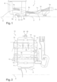
- FIG 1 shows a turbomachine 1 which comprises, in a conventional manner, a fan propeller S, a low pressure compressor 1a, a high pressure compressor 1b, an annular combustion chamber 1c, a high pressure turbine 1d, a low pressure turbine 1e and a nozzle exhaust 1h.
- the high pressure compressor 1b and the high pressure turbine 1d are connected by a high pressure shaft 2 and form with it a high pressure body (HP).
- the low pressure compressor 1a and the low pressure turbine 1e are connected by a low pressure shaft 3 and form with it a low pressure body (LP).
- the fan propeller S is driven by a fan shaft 4 which is coupled to the LP shaft 3 by means of a planetary gear reduction gear 10 shown here schematically.
- the reducer 10 is positioned in the front part of the turbomachine.
- a fixed structure comprising schematically, here, an upstream part 5a and a downstream part 5b is arranged so as to form an enclosure E1 surrounding the reducer 10.
- This enclosure E1 is here closed upstream by joints at the level of a bearing allowing the crossing of the fan shaft 4, and downstream by seals at the level of the crossing of the LP shaft 3.
- the reducer 10 comprises a crown 14 which is fixed by means of a crown carrier (not shown) to the fixed structure 5a, 5b with flexible means arranged to enable it to follow any movements of the drive shaft.
- fan 4 in certain cases of degraded operation for example.
- the crown carrier is made up of a more or less flexible part which drives the crown and of a part maintained by bearings or bearings and on which the fan is mounted.
- the reducer 10 engages on the one hand on the shaft BP3 via splines 7 which drive a planetary or sun gear pinion 11, and on the other hand on the fan shaft 4 which is attached to a door -satellites 13.
- the solar 11, whose axis of rotation X coincides with that of the turbomachine drives a series of satellite gears or satellites 12, which are regularly distributed over the circumference of the reducer 10.
- the number of satellites 12 is generally defined between three and seven.
- the crown 14 which is fixed to a stator of the turbomachine via flanges 20 in the case of an epicyclic or fixed to a rotor of the turbomachine in the case of a planetary.
- Each of the satellites 12 rotates freely around a satellite axis/bearing 16 connected to the planet carrier 13, using a bearing which may be smooth, as shown in the figure 2 , or a bearing with rolling elements (ball or roller bearings).
- FIG. 2 shows the routing of the oil to the reducer 10 and its path inside the latter. Arrows show on the picture 2 the path followed by the oil from, in this example, a buffer tank linked to the fixed structure of the turbomachine, to the pinions and the bearings to be lubricated.
- the lubrication device conventionally comprises three parts: a first part linked to the fixed structure and delivering the oil to the rotating parts of the reducer 10, a spinning wheel with the planet carrier 13 receiving this oil in the case of an epicyclic and a distributor assembled to the planet carrier , which are fixed on a planetary architecture, and oil distribution circuits supplied with oil by the impeller to convey it to the places to be lubricated.
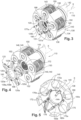
- THE figures 3 to 8 illustrate an embodiment of a reducer 110 according to the invention.
- the reference 130 designates the planet carrier of the reducer 110, which is here of the one-piece type comprising a part forming a cage 134 and a part forming a shaft 142.
- the cage comprises two annular walls 136, 138 coaxial and connected at their periphery by a cylindrical wall 140.
- the annular wall 136 is secured to the substantially cylindrical shaft 142, partially visible, this shaft comprising means of meshing with the fan shaft 4 of the turbomachine.
- the coupling means are for example longitudinal splines.
- the cylindrical wall 140 is perforated and comprises slots 143 crossing in the radial direction allowing the mounting of the satellites 150.
- the wall 138 comprises a central opening 144 (allowing the mounting of the solar panel) centered on the X axis and a series of orifices 146 regularly distributed around the X axis, the opening 144 and the orifices 146 being through in the axial direction ( figure 5 ).
- the holes 146 are used to mount the axes 148 of rotation of the satellites 150.
- the axes 148 are parallel to the axis X and are mounted in the cage 134 by axial translation passing through the holes 146. They are fixed at their longitudinal ends on the walls 136, 138, respectively.
- Each axis 148 is integral with a plain bearing 149 around which the satellite 150 is mounted ( figure 4 ).
- Shaft 148 is hollow and comprises an internal cylindrical cavity 152.
- Shaft 148 and bearing 149 are traversed by at least one radial duct (not visible) which opens at its radially internal end into cavity 152, and at its end radially external in a longitudinal groove of the periphery of the bearing for its oil supply.
- the satellites 150 rotatably mounted on the axes 148 have their outer peripheries which partly pass through the slots 143 with a view to their meshing with the outer crown of the reducer 110 intended to surround the cage 134.
- the planet gears 150 mesh with the sun gear 151 which comprises rectilinear internal splines 151a for coupling to another shaft such as a turbine shaft.
- a wheel 120 is added and fixed to the wall 138, on the side of its external face, that is to say the one which is not located on the side of the satellites 150.
- the function of the wheel 120 is to lubricate the reducer 110 and comprises lubricating means configured to supply lubricant to the nozzles 172 and to the shafts 148 and bearings 149.
- the oil supply to the nozzles 172 makes it possible to lubricate the meshing teeth of the satellites 150 and the sun gear 151 , as will be described in more detail in the following with reference to the figure 8 .
- the impeller 120 has a generally annular shape and comprises arms 120a projecting radially outwards, five in number in the example shown.
- the impeller 120 is intended to be mounted coaxially on the wall 138 and has a face 120b for bearing and fixing on this wall.
- the impeller 120 comprises a central opening 120c delimited on the outside by an annular part defining one or more annular grooves 158a, 158b which are coaxial and arranged axially one beside the other. These grooves 158a, 158b extend around the axis X and emerge radially inwards. Their radially outer bottom wall comprises orifices in fluid communication with radial channels 160, on the one hand, and radial ducts 162, on the other hand ( figure 6 ).
- oil is intended to be squirted into grooves 158a, 158b by lubricant supply means.
- lubricant supply means generally comprise a series of injectors which are arranged around the X axis and pass through the openings 120c, 144. The injectors are carried by a stator and spray lubricant radially outwards directly into the grooves 158a, 158b , which will then flow through channels 160 and conduits 162.
- the number of channels 160 is equal to the number of conduits 162 which is equal to the number of axes 148 and satellites 150. This number is here five.
- the channels 160 are evenly distributed around the X axis and the ducts 162 are evenly distributed around the X axis, each duct 162 being arranged between two adjacent channels 160.
- the ducts and channels are formed in extra thicknesses 165, 166 of the impeller ( picture 3 ).
- the extra thicknesses 165, 166 in which the channels 160 and the ducts 162 are formed extend radially outwards from the part in which the grooves 158a, 158b are formed.
- the extra thicknesses 165 in which the ducts 162 are formed extend over the arms 120a of the impeller.
- the extra thicknesses 166 in which the channels 150 are formed extend over the fingers 120d projecting radially outward from the impeller.
- the fingers 120d have a smaller radial extent than that of the arms 120a and are each placed between two adjacent arms.
- Each of the ducts 162 communicates at its radially outer end with a cavity 152 of a shaft 148 for the supply of lubricant to this shaft 148 and the associated bearing 149 ( figure 6 ).
- the lubricant supplied by the conduits 162 is intended to be injected into the cavities 152, then to flow through the aforementioned conduits to the periphery of the bearings 149.
- Each of the channels 160 communicates at its radially outer end with a longitudinal end of a nozzle 172 visible in particular to the figure 5 And 7 .
- the nozzles 172 have an elongated shape and extend parallel to the axis X. Their axes of elongation are denoted B. They are five in number and regularly distributed around the axis X, each being arranged between two axes 148 adjacent.
- Each channel 160 communicates with cylindrical housings 160a, 160b passing through the wall 138 and the impeller, in which is engaged a longitudinal end portion 172a of the nozzle ( figure 7 ).
- the portion 172a comprises two external annular grooves in which are mounted sealing O-rings which cooperate with the wall of the housing 160a of the impeller, and which are arranged on either side of a transverse channel 173 of the portion 172a intended to be aligned with the channel 160 and therefore in fluid communication with the latter.
- Portion 172a has an external thread at its free end and is connected to an opposite end portion 172b by a fixing lug 175. The free end of this other portion 172b is closed.
- the lug 175 is formed in one piece with the substantially tubular body of the nozzle, and it extends in a plane substantially perpendicular to the longitudinal axis B of this body.
- the lug 175 is intended to be applied against the internal face of the wall 138.
- the lug 175 comprises an orifice for passing a fixing screw 175a, which is screwed into a tapped hole in the wall 138.
- Each nozzle 172 comprises a longitudinal internal cavity 174 connected to the lubricant inlet formed by the channel 160a and furthermore substantially radial orifices 176, distributed along its length, which open into the cavity 174.
- the lubricant supplied by the channels 160 to 'to the nozzles 172 is intended to be sprayed through the orifices 176 on the teeth of the satellites 150 and the solar 151 in operation (cf. figure 8 ).
- the orifices 176 are formed in at least one boss 176a of the body of the nozzle, this boss 176a projecting radially outwards.
- each nozzle 172 comprises two bosses 176a spaced axially from one another with respect to the longitudinal axis B of the nozzle.
- Each boss 176a comprises six orifices 176 divided into two rows of three regularly spaced orifices.
- the number of orifices and rows can of course vary. In the example shown, there is one boss per tooth helix. One row is dedicated for solar and one row is dedicated for a satellite. Furthermore, in the example represented, three jets are assigned per function but this number can vary according to the flow rate required or the need for distribution of the lubrication.
- Each boss 176a has an angular extent ⁇ around the axis of elongation B of the nozzle, which is less than or equal to 360°, and preferably 180° ( figure 8 ). It has here in cross section a generally rectangular, triangular or trapezoidal shape. The sides of the boss 176a are here substantially parallel. Finally, as we see in figure 8 , the tubular wall has a wall thickness E and each boss forms an extra thickness on this wall, which is equal to E′ with E′ greater than or equal to E in the example shown. E' is present to bring the jet exit closer to the sun and also allows the guide length to be increased.
- the orifices 176 are oriented so that the oil is directed towards the teeth to be lubricated.
- the orifices of each row of each boss project oil onto a toothing, these orifices extending in a plane not parallel to that in which the orifices of the other row extend.
- each nozzle 172 is configured to spray oil on the solar 151 and one of the satellites 150.
- a dedicated tool 180 is positioned on the wall 138 ( figure 5 ).
- a centering element 180a of the tool 180 allows it to be centered on the wall 138.
- each nozzle 172 is engaged in the housing 160b of the wall 138 and in the housing 180b of the tool 180. Once the nozzles 172 have been positioned through the cage and the tool, each leg of fixing 175 of the nozzles 172 is brought to rest on the wall 138 and fixed by the screw 175a. The tool 180 can then be removed.
- the solar system, the satellites and the impeller 120 are then mounted.
- the impeller 120 comprises a centering element 120e which ensures the centering of the impeller 120 on the wall 180. Thanks to the centering elements 120e of the impeller and 180b of the tooling, the nozzles 172 have been positioned relative to the cage 140 and to the impeller 120 with sufficient location precision to ensure the insertion of the longitudinal ends of the nozzles 172 into the housings 160a of the impeller 120 despite the hyperstatism of the assembly .
- a nut 177a is then screwed onto each free end 172a of the nozzles 172, so as to hold the impeller 120 in position on the cage 140.
- the invention thus proposes bosses 176a for extending the oil passages in the nozzles up to these orifices. and therefore shortening of the oil jets.
- the nozzles 172 are here mounted from the inside of the cage 134 unlike the prior art.
- the spinning wheel 120 can be mounted prior to the assembly of the cage or at the very end of the assembly process.
- the nozzles 172 are inserted into the housings 160b of the wall 138 of the cage then can be positioned relative to each other using the tool 180 which temporarily replaces the impeller.
- Each nozzle 172 is then clamped using the screw 175a inside the cage and then the positioning tool is removed. After this step, the solar 151, the satellites 150 and their axes 148 can be mounted. Finally, the impeller 120 is fixed on the planet carrier 130 using the nuts screwed on the threaded parts of the nozzles. This assembly sequence is the preferred one even if there are others.
- the inventors sought to identify all the geometric parameters which represent the distance between a nozzle and the solar. Starting from the solar head diameter, and adding an assembly clearance, we obtain a centering diameter of the wheel in the planet carrier. Then, a slight clearance is left for the assembly of the nozzle. This depends on the diameter of the pipe and the thickness of the O-ring. Material is then added to the nozzles, through the bosses, so as to increase the guide length of the jet of lubricant.
Landscapes
- Engineering & Computer Science (AREA)
- General Engineering & Computer Science (AREA)
- Mechanical Engineering (AREA)
- Chemical & Material Sciences (AREA)
- Combustion & Propulsion (AREA)
- General Details Of Gearings (AREA)
- Retarders (AREA)
Description
- La présente invention concerne le domaine des réducteurs de vitesse à train épicycloïdal pour turbomachine en particulier d'aéronef, l'invention concerne un gicleur de lubrifiant pour un tel réducteur. L'invention concerne en outre un ensemble comprenant tels gicleurs et un turbomachine d'aéronef comprenant au moins un de tel gicleur.
- L'état de l'art comprend notamment les documents
WO-A1-2010/092263 ,FR-A1 -2 987 416 CN-A-106 594 248 (qui montre la préambule de la revendication 1),DE-A1-10 2008 004999 FR-A1-3 041 054 - Les turbomachines actuelles, notamment les turbomachines comportant une ou plusieurs hélices soufflant un flux secondaire, comprennent un système de transmission, appelé réducteur, pour entraîner cette ou ces hélices à la bonne vitesse de rotation à partir de l'arbre de la turbine de puissance du corps primaire du moteur.
- Le fonctionnement des réducteurs, en particulier sur des turbomachines avec hélice de soufflante à fort taux de dilution, nécessite un débit d'huile particulièrement important, de l'ordre de 6000 à 7000 litres par heure au décollage, pour assurer la lubrification et le refroidissement de leurs pignons et paliers.
- Parmi les réducteurs utilisés, on trouve les réducteurs planétaire et (à train) épicycloïdal qui ont l'avantage d'offrir des taux de réduction importants de la vitesse de rotation dans des encombrements réduits.
- Un tel réducteur comprend un pignon planétaire ou pignon central, appelé solaire, une couronne extérieure et des pignons satellites, appelés satellites, qui sont en prise avec le solaire et avec la couronne, le support de l'un de ces trois composants devant être bloqué en rotation pour le fonctionnement du train d'engrenages.
- Lorsque le porte-satellites est fixe en rotation, le solaire et la couronne sont menant et mené, respectivement, ou inversement. Le réducteur est alors du type « planétaire ».
- Dans le cas inverse, le plus fréquent, d'un réducteur à train épicycloïdal, la couronne extérieure est fixe en rotation et le solaire et le porte-satellites sont menants et menés.
- Cependant, ce type de réducteur présente des inconvénients. Une des problématiques est lié à la bonne lubrification des dentures des satellites et du solaire. L'huile doit passer d'une partie fixe du moteur à une partie tournante à haute vitesse. Une fois dans la partie tournante, l'huile n'est plus sous pression. A haute vitesse, il est difficile d'atteindre le solaire avec l'huile à cause de l'effet de centrifugation. Il est alors primordial de rapprocher le gicleur au plus près du solaire. Une autre des problématiques est liée à la complexité du montage.
- La présente invention propose un perfectionnement qui apporte une solution simple, efficace et économique à au moins une partie de ces problèmes.
- L'invention concerne un gicleur de lubrifiant pour un réducteur de vitesse à train épicycloïdal de turbomachine, ledit gicleur ayant une forme générale allongée et comportant un corps d'axe longitudinal B, ledit corps comportant une cavité interne longitudinale qui est en communication fluidique avec une entrée de lubrifiant située à une extrémité longitudinale dudit corps et avec des orifices de sortie de lubrifiant qui sont formés dans une paroi annulaire dudit corps et qui s'étendent sensiblement radialement par rapport audit axe B, lesdits orifices sont formés dans au moins un bossage dudit corps, qui est en saillie radialement vers l'extérieur sur ladite paroi caractérisé en ce que le bossage a une étendue angulaire autour dudit axe inférieure à 180°.
- Par opposition à la technique antérieure, un gicleur a ainsi davantage de matière au niveau des orifices de projection d'huile. Cet ajout de matière a la forme d'un bossage au sommet duquel débouchent les orifices. Les orifices ont ainsi une dimension radiale supérieure à celle des orifices d'un gicleur selon la technique antérieure, et ont leurs extrémités radialement externes qui sont à un rayon supérieur et peuvent être rapprochées des dentures à lubrifier. L'huile traversant les orifices est guidée sur une plus longue distance et est projetée au plus près des dentures, ce qui optimise de manière significative la lubrification du réducteur.
- Dans la présente demande, on entend par des orifices sensiblement radiaux des orifices qui ont une orientation sensiblement radiale, c'est-à-dire que chacun de leurs axes est sensiblement confondu avec un rayon, en particulier à l'axe du corps.
- Le gicleur selon l'invention peut comprendre une ou plusieurs des caractéristiques suivantes, prises isolément les unes des autres, ou en combinaison les unes avec les autres :
- le au moins un bossage a en section transversale une forme générale rectangulaire, triangulaire ou en trapézoïdale ; la forme du bossage est ainsi optimisée pour acheminer l'huile au plus près des dentures à lubrifier ;
- le bossage en trapèze comprend une petite base qui est définie par l'extrémité radialement externe du bossage sur laquelle débouchent lesdits orifices, et des flancs qui forment entre eux un angle compris entre 0 et 90° ; l'encombrement des bossages est ainsi réduit ;
- la petite base a une forme incurvée convexe, qui peut être obtenue par tournage par exemple ;
- ledit au moins un bossage comprend au moins une rangée d'orifices par élément à lubrifier ; il comporte par exemple deux rangées comportant chacune plusieurs orifices ; en variante, les orifices pourraient avoir une autre disposition ;
- ledit corps comprend au moins deux bossages à distance longitudinale l'un de l'autre ; les bossages sont situés dans des zones privilégiées du corps du gicleur afin d'optimiser la lubrification des dentures tout en optimisant l'encombrement et la masse du gicleur ; dans notre cas, la zone privilégiée est définie par le nombre et la largeur des hélices des dentures ;
- le gicleur comprend une patte de fixation formée d'une seule pièce avec le corps, ladite patte s'étendant sensiblement dans un plan perpendiculaire audit axe et comportant un orifice de passage d'un moyen de fixation du type vis-écrou ou vis-trou taraudé; le corps du gicleur a ainsi une forme relativement simple, ce qui limite son coût de fabrication ;
- ledit corps comprend au moins une gorge annulaire externe de logement d'un joint annulaire d'étanchéité.
- Selon un autre aspect, l'invention concerne un ensemble comportant un porte-satellites et des gicleurs tels que définis ci-dessus, pour un réducteur de vitesse à train épicycloïdal de turbomachine, ledit porte-satellites comprenant une cage définissant un espace interne de montage d'un solaire central d'axe X de rotation et d'une rangée annulaire de satellites disposés autour de l'axe X et engrenés avec ledit solaire, ledit solaire comportant des moyens d'accouplement à un premier arbre, ladite cage comportant deux parois annulaires sensiblement parallèles centrées sur ledit axe X et une paroi cylindrique reliant lesdites parois annulaires à leur périphérie externe, une première desdites parois annulaires étant reliée à un corps sensiblement cylindrique comportant des moyens d'accouplement à un second arbre, et une seconde desdites parois annulaires comportant des passages pour le montage des gicleurs, par déplacement de chaque gicleur dans une direction sensiblement parallèle audit axe X, caractérisé en ce que lesdits gicleurs sont configurés pour être montés sur ladite seconde paroi depuis l'intérieur de la cage.
- Avantageusement, les gicleurs comprennent chacun une première portion longitudinale comportant lesdits bossages et ladite platine et une seconde portion filetée, la première portion de chaque gicleur étant configurée pour s'étendre à l'intérieur de ladite cage et la portion filetée étant destinée à recevoir un écrou destiné à prendre appui sur une face externe de ladite cage.
- La portion filetée de chaque gicleur peut traverser d'une part un logement d'un rouet rapporté et fixé sur ladite seconde paroi de la cage, et d'autre part un logement de cette seconde paroi.
- Selon un autre aspect, l'invention concerne une turbomachine d'aéronef, caractérisée en ce qu'elle comprend au moins un gicleur ou un ensemble tel que décrit ci-dessus.
- Selon un autre aspect, l'invention concerne un porte-satellites et un procédé d'assemblage d'un porte-satellites tel que décrit ci-dessus, dans lequel il comprend les étapes de :
- fixation des gicleurs à la cage,
- montage des satellites et du solaire dans la cage, et
- fixation du rouet sur la cage.
- D'autres variantes du procédé de montage sont naturellement possible.
- D'autres caractéristiques et avantages ressortiront de la description qui suit d'un mode de réalisation non limitatif de l'invention en référence aux dessins annexés sur lesquels :
- la
figure 1 est une vue schématique en coupe axiale d'une turbomachine utilisant l'invention, - la
figure 2 est une vue en coupe axiale d'un réducteur à train épicycloïdal, - la
figure 3 est une vue schématique en perspective d'un mode de réalisation d'un réducteur à train épicycloïdal, - la
figure 4 est une vue schématique en perspective du réducteur de lafigure 3 , son rouet étant dissocié du reste du réducteur, - la
figure 5 est une vue schématique en perspective d'un ensemble comportant un rouet, des gicleurs et une cage du réducteur de lafigure 3 , cette cage étant partiellement représentée, - la
figure 6 est une autre vue en perspective du rouet du réducteur de lafigure 3 , - la
figure 7 est une vue schématique partielle en coupe axiale et à plus grande échelle d'un détail du réducteur de lafigure 3 , et en particulier d'un gicleur du réducteur, et - la
figure 8 est une vue schématique partielle en coupe transversale et à plus grande échelle d'un détail du réducteur de lafigure 3 , et en particulier d'un gicleur du réducteur. - La
figure 1 montre une turbomachine 1 qui comporte, de manière classique, une hélice de soufflante S, un compresseur basse pression 1a, un compresseur haute pression 1b, une chambre annulaire de combustion 1c, une turbine haute pression 1d, une turbine basse pression 1e et une tuyère d'échappement 1h. Le compresseur haute pression 1b et la turbine haute pression 1d sont reliés par un arbre haute pression 2 et forment avec lui un corps haute pression (HP). Le compresseur basse pression 1a et la turbine basse pression 1e sont reliés par un arbre basse pression 3 et forment avec lui un corps basse pression (BP). - L'hélice de soufflante S est entraînée par un arbre de soufflante 4 qui est couplé à l'arbre BP 3 au moyen d'un réducteur 10 à train épicycloïdal représenté ici schématiquement.
- Le réducteur 10 est positionné dans la partie avant de la turbomachine. Une structure fixe comportant schématiquement, ici, une partie amont 5a et une partie aval 5b est agencée de manière à former un enceinte E1 entourant le réducteur 10. Cette enceinte E1 est ici fermée en amont par des joints au niveau d'un palier permettant la traversée de l'arbre de soufflante 4, et en aval par des joints au niveau de la traversée de l'arbre BP 3.
- En référence à la
figure 2 , le réducteur 10 comprend une couronne 14 qui est fixée par l'intermédiaire d'un porte-couronne (non représenté) à la structure fixe 5a, 5b avec des moyens souples agencés pour lui permettre de suivre les mouvements éventuels de l'arbre de soufflante 4, dans certains cas de fonctionnement dégradés par exemple. Dans une architecture planétaire, le porte-couronne est composé d'une partie plus ou moins souple qui entraine la couronne et d'une partie maintenue par des roulements ou des paliers et sur lequel vient se monter la soufflante. Ces moyens de fixation sont connus de l'homme du métier et ne sont pas détaillés ici. Une brève description peut en être trouvée par exemple dansFR-A1-2987416 - Le réducteur 10 embraye d'une part sur l'arbre BP3 par l'intermédiaire de cannelures 7 qui entraînent un pignon d'engrenage planétaire ou solaire 11, et d'autre part sur l'arbre de soufflante 4 qui est attaché à un porte-satellites 13. Classiquement, le solaire 11, dont l'axe de rotation X est confondu avec celui de la turbomachine, entraîne une série de pignons de satellites ou satellites 12, qui sont répartis régulièrement sur la circonférence du réducteur 10. Le nombre de satellites 12 est généralement défini entre trois et sept. Les satellites 12 tournent aussi autour de l'axe X de la turbomachine sauf dans le cas d'un planétaire où ils tournent uniquement autour de leurs axes de révolution, en engrenant sur des dentures internes de la couronne 14, qui est fixée à un stator de la turbomachine par l'intermédiaire de brides 20 dans le cas d'un épicycloïdal ou fixé à un rotor de la turbomachine dans le cas d'un planétaire. Chacun des satellites 12 tourne librement autour d'un axe/palier de satellite 16 relié au porte-satellite 13, à l'aide d'un palier qui peut être lisse, comme représenté sur la
figure 2 , ou un palier à éléments roulants (roulements à billes ou à rouleaux). - La rotation des satellites 12 autour de leur axe de satellite 16, du fait de la coopération de leurs pignons avec les dentures de la couronne 14, entraîne la rotation du porte-satellites 13 autour de l'axe X, et par conséquent celle de l'arbre de soufflante 4 qui lui est lié, à une vitesse de rotation qui est inférieure à celle de l'arbre BP 3.
- La
figure 2 montre l'acheminement de l'huile vers le réducteur 10 et son cheminement à l'intérieur de celui-ci. Des flèches montrent sur lafigure 2 le cheminement suivi par l'huile depuis, sur cet exemple, un réservoir tampon lié à la structure fixe de la turbomachine, jusqu'aux pignons et aux paliers à lubrifier. Le dispositif de lubrification comporte classiquement trois parties : une première partie liée à la structure fixe et délivrant l'huile vers les parties tournantes du réducteur 10, un rouet tournant avec le porte-satellites 13 réceptionnant cette huile dans le cas d'un épicycloïdal et d'un distributeur assemblé au porte-satellite, qui sont fixes sur une architecture planétaire, et des circuits de distribution d'huile alimentés en huile par le rouet pour l'acheminer vers les endroits à lubrifier. - Les
figures 3 à 8 illustrent un exemple de réalisation d'un réducteur 110 selon l'invention. - La référence 130 désigne le porte-satellites du réducteur 110, qui est ici du type monobloc comprenant une partie formant une cage 134 et une partie formant un fût 142. La cage comporte deux parois annulaires 136, 138 coaxiales et reliées à leur périphérie par une paroi cylindrique 140.
- La paroi annulaire 136 est solidaire du fût 142 sensiblement cylindrique, partiellement visible, ce fût comportant des moyens d'engrènement avec l'arbre de soufflante 4 de la turbomachine. Les moyens d'accouplement sont par exemple des cannelures longitudinales.
- Dans l'exemple représenté, la paroi cylindrique 140 est ajourée et comprend des lumières 143 traversantes en direction radiale permettant le montage des satellites 150.
- La paroi 138 comprend une ouverture centrale 144 (permettant le montage du solaire) centrée sur l'axe X et une série d'orifices 146 régulièrement répartis autour de l'axe X, l'ouverture 144 et les orifices 146 étant traversants en direction axiale (
figure 5 ). - Les orifices 146 servent au montage des axes 148 de rotation des satellites 150. Les axes 148 sont parallèles à l'axe X et sont montés dans la cage 134 par translation axiale en passant par les orifices 146. Ils sont fixés à leurs extrémités longitudinales sur les parois 136, 138, respectivement. Chaque axe 148 est solidaire d'un palier lisse 149 autour duquel est monté le satellite 150 (
figure 4 ). L'axe 148 est creux et comprend une cavité cylindrique interne 152. L'axe 148 et le palier 149 sont traversés par au moins un conduit radial (non visible) qui débouche à son extrémité radialement interne dans la cavité 152, et à son extrémité radialement externe dans une rainure longitudinale de la périphérie du palier en vue de son alimentation en huile. - Comme cela est visible à la
figure 4 , les satellites 150 montés à rotation sur les axes 148 ont leurs périphéries externes qui traversent en partie les lumières 143 en vue de leur engrènement avec la couronne externe du réducteur 110 destinée à entourer la cage 134. - Les satellites 150 engrènent avec le solaire 151 qui comprend des cannelures rectilignes internes 151a d'accouplement à un autre arbre tel qu'un arbre de turbine.
- Un rouet 120 est rapporté et fixé sur la paroi 138, du côté de sa face externe, c'est-à-dire celle qui n'est pas située du côté des satellites 150. Le rouet 120 a pour fonction de lubrifier le réducteur 110 et comprend des moyens de lubrification configurés pour amener du lubrifiant jusqu'à des gicleurs 172 et jusqu'aux axes 148 et paliers 149. L'alimentation en huile des gicleurs 172 permet de lubrifier les dents d'engrènement des satellites 150 et du solaire 151, comme cela sera décrit plus en détail dans ce qui suit en référence à la
figure 8 . - Le rouet 120 a une forme générale annulaire et comprend des bras 120a en saillie radiale vers l'extérieur, au nombre de cinq dans l'exemple représenté.
- Le rouet 120 est destiné à être monté coaxialement sur la paroi 138 et comporte une face 120b d'appui et de fixation sur cette paroi.
- Le rouet 120 comporte une ouverture centrale 120cdélimitée extérieurement par une partie annulaire définissant une ou plusieurs gorges annulaires 158a, 158b coaxiales et disposées axialement l'une à côté de l'autre. Ces gorges 158a, 158b s'étendent autour de l'axe X et débouchent radialement vers l'intérieur. Leur paroi de fond radialement externe comprend des orifices en communication fluidique avec des canaux radiaux 160, d'une part, et des conduits radiaux 162, d'autre part (
figure 6 ). - Bien que cela ne soit pas représenté, de l'huile est destinée à être projetée dans les gorges 158a, 158b par des moyens d'alimentation en lubrifiant. Ces moyens comprennent en général une série d'injecteurs qui sont disposés autour de l'axe X et traversent les ouvertures 120c, 144. Les injecteurs sont portés par un stator et pulvérisent du lubrifiant radialement vers l'extérieur directement dans les gorges 158a, 158b, qui va ensuite s'écouler dans les canaux 160 et conduits 162.
- Dans l'exemple représenté, le nombre de canaux 160 est égal au nombre de conduits 162 qui est égal au nombre d'axes 148 et de satellites 150. Ce nombre est ici de cinq. Les canaux 160 sont régulièrement répartis autour de l'axe X et les conduits 162 sont régulièrement répartis autour de l'axe X, chaque conduit 162 étant disposé entre deux canaux 160 adjacents. Les conduits et canaux sont formés dans des surépaisseurs 165, 166 du rouet (
figure 3 ). Les surépaisseurs 165, 166 dans lesquelles sont formés les canaux 160 et les conduits 162 s'étendent radialement vers l'extérieur depuis la partie dans laquelle sont formées les gorges 158a, 158b. Les surépaisseurs 165 dans lesquelles sont formés les conduits 162 s'étendent sur les bras 120a du rouet. On peut considérer que les surépaisseurs 166 dans lesquelles sont formés les canaux 150 s'étendent sur des doigts 120d en saillie radiale vers l'extérieur du rouet. Les doigts 120d ont une étendue radiale inférieure à celle des bras 120a et sont chacun disposés entre deux bras adjacents. - Chacun des conduits 162 communique à son extrémité radialement externe avec une cavité 152 d'un axe 148 en vue de l'alimentation en lubrifiant de cet axe 148 et du palier 149 associé (
figure 6 ). Le lubrifiant amené par les conduits 162 est destiné à être injecté dans les cavités 152, puis à s'écouler à travers les conduits précités jusqu'à la périphérie des paliers 149. - Chacun des canaux 160 communique à son extrémité radialement externe avec une extrémité longitudinale d'un gicleur 172 visible notamment aux
figures 5 et7 . Les gicleurs 172 ont une forme allongée et s'étendent parallèlement à l'axe X. Leurs axes d'allongement sont notés B. Ils sont au nombre de cinq et régulièrement répartis autour de l'axe X en étant chacun disposés entre deux axes 148 adjacents. Chaque canal 160 communique avec des logements cylindriques 160a, 160b traversants de la paroi 138 et du rouet, dans lesquels est engagée une portion d'extrémité longitudinale 172a du gicleur (figure 7 ). La portion 172a comprend deux gorges annulaires externes dans lesquelles sont montées des joints toriques d'étanchéité qui coopèrent avec la paroi du logement 160a du rouet, et qui sont disposés de part et d'autre d'un canal transversal 173 de la portion 172a destiné à être aligné avec le canal 160 et donc en communication fluidique avec ce dernier. La portion 172a comporte un filetage externe à son extrémité libre et est reliée à une portion d'extrémité 172b opposée par une patte de fixation 175. L'extrémité libre de cette autre portion 172b est fermée. - La patte 175 est formée d'une seule pièce avec le corps sensiblement tubulaire du gicleur, et elle s'étend dans un plan sensiblement perpendiculaire à l'axe longitudinal B de ce corps.
- Comme on le voit aux
figures 5 et8 , la patte 175 est destinée à être appliquée contre la face interne de la paroi 138. La patte 175 comprend un orifice de passage d'une vis de fixation 175a, qui est vissée dans un trou taraudé de la paroi 138. - Chaque gicleur 172 comprend une cavité interne longitudinale 174 reliée à l'entrée de lubrifiant formée par le canal 160a et en outre des orifices 176 sensiblement radiaux, répartis sur sa longueur, qui débouchent dans la cavité 174. Le lubrifiant amené par les canaux 160 jusqu'aux gicleurs 172 est destiné à être pulvérisé par les orifices 176 sur les dentures des satellites 150 et du solaire 151 en fonctionnement (cf.
figure 8 ). - Comme on le voit mieux aux
figures 5 et7 , les orifices 176 sont formés dans au moins un bossage 176a du corps du gicleur, ce bossage 176a étant en saillie radialement vers l'extérieur. - Dans l'exemple représenté, chaque gicleur 172 comprend deux bossages 176a espacés axialement l'un de l'autre vis-à-vis de l'axe longitudinal B du gicleur. Chaque bossage 176a comprend six orifices 176 répartis en deux rangées de trois orifices régulièrement espacés. Le nombre d'orifices et de rangées peut naturellement varier. Dans l'exemple représenté, il y a un bossage par hélice de dent. Une rangée est dédiée pour le solaire et une rangée est dédiée pour un satellite. Par ailleurs, dans l'exemple représenté, trois jets sont assignés par fonction mais ce nombre peut varier selon le débit nécessaire ou le besoin de répartition de la lubrification.
- Chaque bossage 176a a une étendue angulaire β autour de l'axe d'allongement B du gicleur, qui est inférieure ou égale à 360°, et de préférence à 180° (
figure 8 ). Il a ici en section transversale une forme générale rectangulaire, triangulaire ou en trapézoïdale. Les flancs du bossage 176a sont ici sensiblement parallèles. Enfin, comme on le voit à lafigure 8 , la paroi tubulaire a une épaisseur de paroi E et chaque bossage forme une surépaisseur sur cette paroi, qui est égale à E' avec E' supérieure ou égale à E dans l'exemple représenté. E' est présent pour rapprocher la sortie de jet du solaire et permet aussi d'augmenter la longueur de guidage. - Les orifices 176 sont orientés de façon à ce que l'huile soit orientée vers les dentures à lubrifier. Dans l'exemple représenté, les orifices de chaque rangée de chaque bossage projettent de l'huile sur une denture, ces orifices s'étendant dans un plan non parallèle à celui dans lequel s'étendent les orifices de l'autre rangée. Dans l'exemple représenté, chaque gicleur 172 est configuré pour projeter de l'huile sur le solaire 151 et un des satellites 150.
- Un outillage 180 dédié est positionné sur la paroi 138 (
figure 5 ). Un élément de centrage 180a de l'outillage 180 permet de le centrer sur la paroi 138. - La portion d'extrémité longitudinale 172a de chaque gicleur 172 est engagée dans le logement 160b de la paroi 138 et dans le logement 180b de l'outillage 180. Une fois les gicleurs 172 positionnés à travers la cage et l'outillage, chaque patte de fixation 175 des gicleurs 172 est mise en appui sur la paroi 138 et fixée par la vis 175a. L'outillage 180 peut alors être retiré.
- On procède ensuite au montage du solaire, des satellites et du rouet 120. Le rouet 120 comporte un élément de centrage 120e qui permet d'assurer le centrage du rouet 120 sur la paroi 180. Grâce aux éléments de centrage 120e du rouet et 180b de l'outillage, les gicleurs 172 ont été positionnés par rapport à la cage 140 et au rouet 120 avec une précision de localisation suffisante pour assurer l'insertion des extrémités longitudinales des gicleurs 172 dans les logements 160a du rouet 120 malgré l'hyperstatisme du montage.
- Un écrou 177a est ensuite vissé sur chaque extrémité libre 172a des gicleurs 172, de façon à maintenir en position le rouet 120 sur la cage 140.
- Dans la position montée des gicleurs 172 sur le porte-satellites 130 représentée à la
figure 5 , les bossages 176a des gicleurs sont orientés plutôt radialement vers l'intérieur. - Afin de rapprocher les orifices 176 de projection d'huile portés par les gicleurs 172 au plus près des dentures du solaire et des satellites, l'invention propose ainsi des bossages 176a de rallongement des passages d'huile dans les gicleurs jusqu'à ces orifices et donc de raccourcissement des jets d'huile. Par ailleurs, les gicleurs 172 sont ici montés par l'intérieur de la cage 134 contrairement à la technique antérieure. Le rouet 120 peut être monté préalablement à l'assemblage de la cage ou tout à la fin du processus de montage. Les gicleurs 172 sont insérés dans les logements 160b de la paroi 138 de la cage puis peuvent être positionnés les uns par rapport aux autres à l'aide de l'outillage 180 qui remplace temporairement le rouet. Chaque gicleur 172 est ensuite bridé à l'aide de la vis 175a à l'intérieur de la cage puis l'outillage de positionnement est retiré. Après cette étape, le solaire 151, les satellites 150 et leurs axes 148 peuvent être montés. Enfin, le rouet 120 est fixé sur le porte-satellite 130 à l'aide des écrous vissés sur les parties filetées des gicleurs. Cette séquence de montage est celle préférée même s'il en existe d'autres.
- Dans le cadre de la présente invention, les inventeurs ont cherché à identifier tous les paramètres géométriques qui représentent la distance entre un gicleur et le solaire. En partant du diamètre de tête du solaire, et en y ajoutant un jeu de montage, on obtient un diamètre de centrage du rouet dans le porte-satellite. Ensuite, un léger jeu est laissé pour le montage du gicleur. Celui-ci dépend du diamètre de la canalisation et de l'épaisseur du joint torique. De la matière est ensuite ajoutée sur les gicleurs, par le biais des bossages, de façon à augmenter la longueur de guidage du jet de lubrifiant.
Claims (10)
- Gicleur (172) de lubrifiant pour un réducteur de vitesse à train épicycloïdal de turbomachine, ledit gicleur ayant une forme générale allongée et comportant un corps d'axe longitudinal B, ledit corps comportant une cavité interne longitudinale (174) qui est en communication fluidique avec une entrée de lubrifiant située à une extrémité longitudinale (172a) dudit corps et avec des orifices (176) de sortie de lubrifiant qui sont formés dans une paroi annulaire dudit corps et qui s'étendent sensiblement radialement par rapport audit axe longitudinal lesdits orifices sont formés dans au moins un bossage (176a) dudit corps, qui est en saillie radialement vers l'extérieur sur ladite paroi caractérisé en ce que le bossage (176a) a une étendue angulaire (β-Fig.8) autour dudit axe longitudinal B inférieure à 180°.
- Gicleur (172) selon la revendication précédente, dans lequel le au moins un bossage (176a) a en section transversale une forme générale rectangulaire, triangulaire ou en trapézoïdale.
- Gicleur (172) selon la revendication précédente, dans lequel le bossage (176a) en trapèze comprend une petite base qui est définie par l'extrémité radialement externe du bossage (176a) sur laquelle débouchent lesdits orifices (176), et des flancs qui forment entre eux un angle (α) compris entre 0 et 90°.
- Gicleur (172) selon l'une des revendications précédentes, dans lequel ledit corps comprend au moins deux bossages (176a) à distance longitudinale l'un de l'autre.
- Gicleur (172) selon l'une des revendications précédentes, dans lequel ledit corps comprend au moins une gorge annulaire externe de logement d'un joint annulaire d'étanchéité.
- Gicleur (172) selon l'une des revendications précédentes, comprenant une patte de fixation (175) formée d'une seule pièce avec le corps, ladite patte s'étendant sensiblement dans un plan perpendiculaire audit axe et comportant un orifice de passage d'un moyen de fixation du type vis-écrou ou vis-trou taraudé.
- Ensemble comportant un porte-satellites (130) et des gicleurs (172) selon l'une des revendications précédentes, pour un réducteur de vitesse à train épicycloïdal de turbomachine, ledit porte-satellites comprenant une cage (134) définissant un espace interne de montage d'un solaire central (151) d'axe X de rotation et d'une rangée annulaire de satellites (150) disposés autour de l'axe X et engrenés avec ledit solaire, ledit solaire comportant des moyens d'accouplement à un premier arbre, ladite cage comportant deux parois annulaires (136, 138) sensiblement parallèles centrées sur ledit axe X et une paroi cylindrique (140) reliant lesdites parois annulaires à leur périphérie externe, une première (136) desdites parois annulaires étant reliée à un corps (142) sensiblement cylindrique comportant des moyens d'accouplement à un second arbre, et une seconde (138) desdites parois annulaires comportant des passages pour le montage des gicleurs, par déplacement de chaque gicleur (172) dans une direction sensiblement parallèle audit axe X, caractérisé en ce que lesdits gicleurs (172) sont configurés pour être montés préalablement sur ladite seconde paroi depuis l'intérieur de la cage.
- Ensemble selon la revendication précédente, les gicleurs (172) étant tels que définis à la revendication 6, dans lequel lesdits gicleurs comprennent chacun une première portion longitudinale comportant lesdits bossages (176a) et ladite patte (175) et une seconde portion filetée, la première portion de chaque gicleur étant configurée pour s'étendre à l'intérieur de ladite cage (134) et la portion filetée étant destinée à recevoir un écrou (177a) destiné à prendre appui sur une face externe de ladite cage.
- Ensemble selon la revendication 8, dans lequel la portion filetée de chaque gicleur (172) traverse d'une part un logement (160a) d'un rouet (120) rapporté et fixé sur ladite seconde paroi (138) de la cage, et d'autre part un logement (160b) de cette seconde paroi.
- Turbomachine d'aéronef, caractérisée en ce qu'elle comprend un réducteur de vitesse à train épicycloïdal comportant au moins un gicleur (172) selon l'une des revendications 1 à 6 ou un ensemble selon l'une des revendication 7 à 9.
Applications Claiming Priority (3)
| Application Number | Priority Date | Filing Date | Title |
|---|---|---|---|
| FR1756894A FR3069300B1 (fr) | 2017-07-20 | 2017-07-20 | Ensemble comportant un rouet de lubrification et des gicleurs de lubrifiant, pour un reducteur de vitesse a train epicycloidal de turbomachine |
| FR1761760A FR3069301B1 (fr) | 2017-07-20 | 2017-12-07 | Gicleur de lubrifiant pour un reducteur de vitesse a train epicycloidal de turbomachine |
| PCT/FR2018/051870 WO2019016491A1 (fr) | 2017-07-20 | 2018-07-20 | Gicleur de lubrifiant pour un reducteur de vitesse a train epicycloïdal de turbomachine |
Publications (2)
| Publication Number | Publication Date |
|---|---|
| EP3655679A1 EP3655679A1 (fr) | 2020-05-27 |
| EP3655679B1 true EP3655679B1 (fr) | 2023-03-29 |
Family
ID=59746209
Family Applications (2)
| Application Number | Title | Priority Date | Filing Date |
|---|---|---|---|
| EP18755513.1A Active EP3655680B1 (fr) | 2017-07-20 | 2018-07-16 | Porte-satellites pour un réducteur de vitesse à train épicycloidal de turbomachine et procédé d'assemblage d'un tel porte-satellites |
| EP18758923.9A Active EP3655679B1 (fr) | 2017-07-20 | 2018-07-20 | Gicleur de lubrifiant pour un reducteur de vitesse a train epicycloïdal de turbomachine |
Family Applications Before (1)
| Application Number | Title | Priority Date | Filing Date |
|---|---|---|---|
| EP18755513.1A Active EP3655680B1 (fr) | 2017-07-20 | 2018-07-16 | Porte-satellites pour un réducteur de vitesse à train épicycloidal de turbomachine et procédé d'assemblage d'un tel porte-satellites |
Country Status (5)
| Country | Link |
|---|---|
| US (2) | US11112001B2 (fr) |
| EP (2) | EP3655680B1 (fr) |
| CN (2) | CN110914576A (fr) |
| FR (2) | FR3069300B1 (fr) |
| WO (1) | WO2019016463A1 (fr) |
Cited By (1)
| Publication number | Priority date | Publication date | Assignee | Title |
|---|---|---|---|---|
| WO2025262388A1 (fr) * | 2024-06-20 | 2025-12-26 | Safran Transmission Systems | Rouet de distribution d'huile pour un réducteur de vitesse |
Families Citing this family (29)
| Publication number | Priority date | Publication date | Assignee | Title |
|---|---|---|---|---|
| US10683773B2 (en) * | 2018-05-25 | 2020-06-16 | Pratt & Whitney Canada Corp. | Planetary gearbox having compliant journal bearings |
| FR3092889B1 (fr) | 2019-02-14 | 2021-12-03 | Safran Trans Systems | Lubrification d’un porte-satellites pour un reducteur mecanique de turbomachine, en particulier d’aeronef |
| FR3092888B1 (fr) * | 2019-02-14 | 2021-01-22 | Safran Trans Systems | Lubrification d’un porte-satellites pour un reducteur mecanique de turbomachine, en particulier d’aeronef |
| FR3098562B1 (fr) * | 2019-07-08 | 2021-06-11 | Safran Trans Systems | Couvercle de canalisation d’huile et reducteur mecanique de turbomachine d’aeronef comportant un tel couvercle |
| FR3103241B1 (fr) * | 2019-11-15 | 2021-12-17 | Safran Trans Systems | Rouet pour un porte-satellites de reducteur de vitesse a train epicycloïdal de turbomachine |
| FR3103243B1 (fr) | 2019-11-15 | 2022-07-15 | Safran Trans Systems | Rouet etage pour l’alimentation en huile d’un reducteur epicycloïdal ou planetaire. |
| US11473507B2 (en) * | 2020-08-04 | 2022-10-18 | Ge Avio S.R.L. | Gearbox efficiency rating for turbomachine engines |
| US11365688B2 (en) | 2020-08-04 | 2022-06-21 | G.E. Avio S.r.l. | Gearbox efficiency rating for turbomachine engines |
| US11486312B2 (en) * | 2020-08-04 | 2022-11-01 | Ge Avio S.R.L. | Gearbox efficiency rating for turbomachine engines |
| US11401829B2 (en) * | 2020-08-04 | 2022-08-02 | Ge Avio S.R.L. | Gearbox efficiency rating for turbomachine engines |
| FR3113934B1 (fr) | 2020-09-04 | 2022-10-28 | Safran Trans Systems | Reducteur mecanique de turbomachine d’aeronef |
| FR3115087B1 (fr) | 2020-10-08 | 2024-04-12 | Safran Trans Systems | Reducteur mecanique de turbomachine d’aeronef |
| FR3119431A1 (fr) * | 2021-02-03 | 2022-08-05 | Safran Transmission Systems | Réducteur mécanique |
| FR3120657B1 (fr) | 2021-03-10 | 2023-03-03 | Safran Trans Systems | Refroidissement de pignons d’un réducteur mécanique d’une turbomachine |
| EP4341586B1 (fr) * | 2021-05-19 | 2026-05-06 | Cummins, Inc. | Pulvérisateurs de fluide pour groupes motopropulseurs et leurs procédés de fabrication |
| CN114215951B (zh) * | 2021-11-22 | 2023-06-06 | 浙江华章科技有限公司 | 一种稀释水横幅定量调节系统的智能执行器 |
| IT202100029891A1 (it) * | 2021-11-25 | 2023-05-25 | Ge Avio Srl | Impianto di lubrificazione integrato |
| EP4198351A1 (fr) * | 2021-12-20 | 2023-06-21 | Flender GmbH | Engrenage pourvu d'élément de pulvérisation d'huile |
| IT202200001613A1 (it) | 2022-01-31 | 2023-07-31 | Gen Electric | Valutazione di efficienza motoristica complessiva per motori a turbomacchina |
| IT202300013707A1 (it) * | 2023-06-30 | 2024-12-30 | Ge Avio Srl | Impianto di lubrificazione per un gruppo ingranaggi |
| EP4484801A1 (fr) * | 2023-06-30 | 2025-01-01 | GE Avio S.r.l. | Système de lubrification pour un ensemble d'engrenages |
| US12092200B1 (en) | 2023-08-23 | 2024-09-17 | Allison Transmission, Inc. | Lubrication of a planetary gear system |
| US12135076B1 (en) * | 2023-09-29 | 2024-11-05 | Rtx Corporation | Fluid device(s) for supporting rotating structure(s) of a turbine engine |
| FR3156497A1 (fr) | 2023-12-06 | 2025-06-13 | Safran Transmission Systems | Gicleur d’huile pour un reducteur de turbomachine d’aeronef |
| US12516725B2 (en) * | 2024-02-19 | 2026-01-06 | Toyota Motor Engineering & Manufacturing North America, Inc. | Planetary pinion oil delivery device |
| FR3159631B1 (fr) | 2024-02-23 | 2026-01-30 | Safran Trans Systems | Dispositif d’alimentation en huile pour un reducteur mecanique d’une turbomachine d’aeronef |
| US12560125B2 (en) | 2024-06-14 | 2026-02-24 | General Electric Company | Gas turbine engine with acoustic spacing of the fan blades and outlet guide vanes |
| US12428962B1 (en) | 2024-06-14 | 2025-09-30 | General Electric Company | Gas turbine engine with acoustic spacing of the fan blades and outlet guide vanes |
| DE102024206499A1 (de) * | 2024-07-10 | 2026-01-15 | Zf Friedrichshafen Ag | Planetengetriebe mit einer Schmiermittelverteilungsvorrichtung |
Citations (1)
| Publication number | Priority date | Publication date | Assignee | Title |
|---|---|---|---|---|
| US20120222761A1 (en) * | 2009-11-16 | 2012-09-06 | Bell Helicopter Tetron Inc. | Dual-Path Fluid Injection Jet |
Family Cites Families (16)
| Publication number | Priority date | Publication date | Assignee | Title |
|---|---|---|---|---|
| DE102005031592A1 (de) * | 2005-07-06 | 2007-01-11 | Schaeffler Kg | Planetenradträger für ein Planetengetriebe |
| US8667688B2 (en) * | 2006-07-05 | 2014-03-11 | United Technologies Corporation | Method of assembly for gas turbine fan drive gear system |
| DE102008004999B4 (de) * | 2008-01-17 | 2016-12-01 | Jopp Holding GmbH | Vorrichtung zur Erzeugung eines fächerförmigen Strahls und Verfahren zur Herstellung der Vorrichtung |
| FR2942284B1 (fr) | 2009-02-16 | 2011-03-04 | Snecma | Lubrification et refroidissement d'un reducteur a train d'engrenages epicycloidal |
| WO2012048708A1 (fr) * | 2010-10-15 | 2012-04-19 | Ringkøbing Maskinværksted A/S | Dispositif de lubrification |
| US8172717B2 (en) * | 2011-06-08 | 2012-05-08 | General Electric Company | Compliant carrier wall for improved gearbox load sharing |
| CN102829166B (zh) * | 2011-06-18 | 2014-09-24 | 南车戚墅堰机车车辆工艺研究所有限公司 | 一种行星系啮合强制润滑系统 |
| FR2977291B1 (fr) * | 2011-06-29 | 2013-11-22 | Peugeot Citroen Automobiles Sa | Systeme porte satellites pour train epicycloidal |
| EP2610525B1 (fr) * | 2011-12-30 | 2017-09-06 | LEONARDO S.p.A. | Engrenage planétaire pour un aéronef à vol stationaire avec des gicleurs de lubrification |
| US9404420B2 (en) * | 2012-02-23 | 2016-08-02 | Snecma | Device for recovering lubricating oil from an epicyclic reduction gear |
| FR2987416B1 (fr) | 2012-02-23 | 2015-09-04 | Snecma | Dispositif de lubrification d'un reducteur epicycloidal. |
| JP6078160B2 (ja) * | 2012-09-28 | 2017-02-08 | ユナイテッド テクノロジーズ コーポレイションUnited Technologies Corporation | ガスタービンファン駆動ギアシステムの組立方法 |
| FR3009594B1 (fr) * | 2013-08-08 | 2016-12-09 | Snecma | Reducteur a train epicycloidal avec canalisations de transfert de fluide, et turbomachine a helice(s) pour aeronef avec un tel reducteur |
| FR3036763B1 (fr) * | 2015-05-27 | 2017-05-26 | Hispano-Suiza | Reducteur a train epicycloidal |
| FR3041054B1 (fr) | 2015-09-15 | 2017-09-15 | Hispano-Suiza | Dispositif d'alimentation en huile pour un reducteur a train epicycloidal. |
| CN106594248B (zh) * | 2016-12-12 | 2019-05-14 | 中国燃气涡轮研究院 | 一种用于高速重载锥齿轮的多点径向喷射供油喷嘴 |
-
2017
- 2017-07-20 FR FR1756894A patent/FR3069300B1/fr active Active
- 2017-12-07 FR FR1761760A patent/FR3069301B1/fr active Active
-
2018
- 2018-07-16 WO PCT/FR2018/051808 patent/WO2019016463A1/fr not_active Ceased
- 2018-07-16 US US16/631,103 patent/US11112001B2/en active Active
- 2018-07-16 EP EP18755513.1A patent/EP3655680B1/fr active Active
- 2018-07-16 CN CN201880047530.8A patent/CN110914576A/zh active Pending
- 2018-07-20 CN CN201880045550.1A patent/CN110869650A/zh active Pending
- 2018-07-20 EP EP18758923.9A patent/EP3655679B1/fr active Active
- 2018-07-20 US US16/630,394 patent/US11396940B2/en active Active
Patent Citations (1)
| Publication number | Priority date | Publication date | Assignee | Title |
|---|---|---|---|---|
| US20120222761A1 (en) * | 2009-11-16 | 2012-09-06 | Bell Helicopter Tetron Inc. | Dual-Path Fluid Injection Jet |
Cited By (2)
| Publication number | Priority date | Publication date | Assignee | Title |
|---|---|---|---|---|
| WO2025262388A1 (fr) * | 2024-06-20 | 2025-12-26 | Safran Transmission Systems | Rouet de distribution d'huile pour un réducteur de vitesse |
| FR3163703A1 (fr) * | 2024-06-20 | 2025-12-26 | Safran Transmission Systems | Rouet de distribution d’huile pour un réducteur de vitesse |
Also Published As
| Publication number | Publication date |
|---|---|
| EP3655679A1 (fr) | 2020-05-27 |
| US11112001B2 (en) | 2021-09-07 |
| CN110869650A (zh) | 2020-03-06 |
| US20210087946A1 (en) | 2021-03-25 |
| FR3069301B1 (fr) | 2021-11-05 |
| EP3655680A1 (fr) | 2020-05-27 |
| FR3069300A1 (fr) | 2019-01-25 |
| FR3069300B1 (fr) | 2019-07-26 |
| WO2019016463A1 (fr) | 2019-01-24 |
| FR3069301A1 (fr) | 2019-01-25 |
| US20200132186A1 (en) | 2020-04-30 |
| US11396940B2 (en) | 2022-07-26 |
| EP3655680B1 (fr) | 2025-11-19 |
| CN110914576A (zh) | 2020-03-24 |
Similar Documents
| Publication | Publication Date | Title |
|---|---|---|
| FR3069301A1 (fr) | Gicleur de lubrifiant pour un reducteur de vitesse a train epicycloidal de turbomachine | |
| EP3710727B1 (fr) | Réducteur de vitesse a train planétaire ou épicycloïdal de turbomachine | |
| WO2019016491A1 (fr) | Gicleur de lubrifiant pour un reducteur de vitesse a train epicycloïdal de turbomachine | |
| EP3827186B1 (fr) | Reducteur de vitesse a train planetaire ou epicycloidal pour turbomachine | |
| EP3495692B1 (fr) | Couronne de reducteur de vitesse a train planetaire de turbomachine | |
| EP3649373B1 (fr) | Couronne de reducteur epicycloidal ou planetaire pour une turbomachine | |
| EP3649378B1 (fr) | Couronne de reducteur epicycloïdal ou planetaire pour une turbomachine | |
| EP3705705B1 (fr) | Réducteur mécanique de turbomachine d'aéronef | |
| EP3763971A1 (fr) | Couvercle de canalisation d'huile et reducteur mecanique de turbomachine d'aeronef comportant un tel couvercle | |
| WO2019053371A1 (fr) | Pivot pour palier lisse | |
| EP4336070B1 (fr) | Ensemble d'entrainement pour un reducteur mecanique de turbomachine d'aeronef | |
| EP4336059B1 (fr) | Palier lisse pour un réducteur mécanique de turbomachine d'aéronef | |
| EP3699460B1 (fr) | Solaire pour un réducteur mécanique de turbomachine d'aéronef | |
| EP3696448B1 (fr) | Lubrification d'un porte-satellites pour un reducteur mecanique de turbomachine, en particulier d'aeronef | |
| FR3071293A1 (fr) | Reducteur de vitesse a train planetaire ou epicycloidal de turbomachine | |
| EP4023909B1 (fr) | Porte-satellites pour un reducteur mecanique de turbomachine d aeronef | |
| EP3807508B1 (fr) | Porte-satellites tournant pour un reducteur mecanique d'une turbomachine | |
| WO2024209148A1 (fr) | Couronne mobile pour un reducteur mecanique d'aeronef | |
| EP3807507B1 (fr) | Dispositif de repartition d'huile pour un porte-satellites tournant d'un reducteur mecanique d'une turbomachine | |
| WO2026003458A1 (fr) | Reducteur mecanique pour une turbomachine d'aeronef | |
| FR3163977A1 (fr) | Reducteur mecanique pour une turbomachine d’aeronef | |
| WO2026003457A1 (fr) | Reducteur mecanique pour une turbomachine d'aeronef | |
| WO2025176957A1 (fr) | Dispositif d'alimentation en huile pour un reducteur mecanique d'une turbomachine d'aeronef | |
| FR3151639A1 (fr) | Reducteur mecanique pour une turbomachine |
Legal Events
| Date | Code | Title | Description |
|---|---|---|---|
| STAA | Information on the status of an ep patent application or granted ep patent |
Free format text: STATUS: UNKNOWN |
|
| STAA | Information on the status of an ep patent application or granted ep patent |
Free format text: STATUS: THE INTERNATIONAL PUBLICATION HAS BEEN MADE |
|
| PUAI | Public reference made under article 153(3) epc to a published international application that has entered the european phase |
Free format text: ORIGINAL CODE: 0009012 |
|
| STAA | Information on the status of an ep patent application or granted ep patent |
Free format text: STATUS: REQUEST FOR EXAMINATION WAS MADE |
|
| 17P | Request for examination filed |
Effective date: 20200114 |
|
| AK | Designated contracting states |
Kind code of ref document: A1 Designated state(s): AL AT BE BG CH CY CZ DE DK EE ES FI FR GB GR HR HU IE IS IT LI LT LU LV MC MK MT NL NO PL PT RO RS SE SI SK SM TR |
|
| AX | Request for extension of the european patent |
Extension state: BA ME |
|
| DAV | Request for validation of the european patent (deleted) | ||
| DAX | Request for extension of the european patent (deleted) | ||
| STAA | Information on the status of an ep patent application or granted ep patent |
Free format text: STATUS: EXAMINATION IS IN PROGRESS |
|
| 17Q | First examination report despatched |
Effective date: 20210804 |
|
| GRAP | Despatch of communication of intention to grant a patent |
Free format text: ORIGINAL CODE: EPIDOSNIGR1 |
|
| STAA | Information on the status of an ep patent application or granted ep patent |
Free format text: STATUS: GRANT OF PATENT IS INTENDED |
|
| INTG | Intention to grant announced |
Effective date: 20221107 |
|
| GRAS | Grant fee paid |
Free format text: ORIGINAL CODE: EPIDOSNIGR3 |
|
| GRAA | (expected) grant |
Free format text: ORIGINAL CODE: 0009210 |
|
| STAA | Information on the status of an ep patent application or granted ep patent |
Free format text: STATUS: THE PATENT HAS BEEN GRANTED |
|
| AK | Designated contracting states |
Kind code of ref document: B1 Designated state(s): AL AT BE BG CH CY CZ DE DK EE ES FI FR GB GR HR HU IE IS IT LI LT LU LV MC MK MT NL NO PL PT RO RS SE SI SK SM TR |
|
| REG | Reference to a national code |
Ref country code: CH Ref legal event code: EP |
|
| REG | Reference to a national code |
Ref country code: DE Ref legal event code: R096 Ref document number: 602018047771 Country of ref document: DE |
|
| REG | Reference to a national code |
Ref country code: AT Ref legal event code: REF Ref document number: 1556879 Country of ref document: AT Kind code of ref document: T Effective date: 20230415 |
|
| REG | Reference to a national code |
Ref country code: IE Ref legal event code: FG4D Free format text: LANGUAGE OF EP DOCUMENT: FRENCH |
|
| REG | Reference to a national code |
Ref country code: LT Ref legal event code: MG9D |
|
| PG25 | Lapsed in a contracting state [announced via postgrant information from national office to epo] |
Ref country code: RS Free format text: LAPSE BECAUSE OF FAILURE TO SUBMIT A TRANSLATION OF THE DESCRIPTION OR TO PAY THE FEE WITHIN THE PRESCRIBED TIME-LIMIT Effective date: 20230329 Ref country code: NO Free format text: LAPSE BECAUSE OF FAILURE TO SUBMIT A TRANSLATION OF THE DESCRIPTION OR TO PAY THE FEE WITHIN THE PRESCRIBED TIME-LIMIT Effective date: 20230629 Ref country code: LV Free format text: LAPSE BECAUSE OF FAILURE TO SUBMIT A TRANSLATION OF THE DESCRIPTION OR TO PAY THE FEE WITHIN THE PRESCRIBED TIME-LIMIT Effective date: 20230329 Ref country code: LT Free format text: LAPSE BECAUSE OF FAILURE TO SUBMIT A TRANSLATION OF THE DESCRIPTION OR TO PAY THE FEE WITHIN THE PRESCRIBED TIME-LIMIT Effective date: 20230329 Ref country code: HR Free format text: LAPSE BECAUSE OF FAILURE TO SUBMIT A TRANSLATION OF THE DESCRIPTION OR TO PAY THE FEE WITHIN THE PRESCRIBED TIME-LIMIT Effective date: 20230329 |
|
| REG | Reference to a national code |
Ref country code: NL Ref legal event code: MP Effective date: 20230329 |
|
| REG | Reference to a national code |
Ref country code: AT Ref legal event code: MK05 Ref document number: 1556879 Country of ref document: AT Kind code of ref document: T Effective date: 20230329 |
|
| PG25 | Lapsed in a contracting state [announced via postgrant information from national office to epo] |
Ref country code: SE Free format text: LAPSE BECAUSE OF FAILURE TO SUBMIT A TRANSLATION OF THE DESCRIPTION OR TO PAY THE FEE WITHIN THE PRESCRIBED TIME-LIMIT Effective date: 20230329 Ref country code: NL Free format text: LAPSE BECAUSE OF FAILURE TO SUBMIT A TRANSLATION OF THE DESCRIPTION OR TO PAY THE FEE WITHIN THE PRESCRIBED TIME-LIMIT Effective date: 20230329 Ref country code: GR Free format text: LAPSE BECAUSE OF FAILURE TO SUBMIT A TRANSLATION OF THE DESCRIPTION OR TO PAY THE FEE WITHIN THE PRESCRIBED TIME-LIMIT Effective date: 20230630 Ref country code: FI Free format text: LAPSE BECAUSE OF FAILURE TO SUBMIT A TRANSLATION OF THE DESCRIPTION OR TO PAY THE FEE WITHIN THE PRESCRIBED TIME-LIMIT Effective date: 20230329 |
|
| PG25 | Lapsed in a contracting state [announced via postgrant information from national office to epo] |
Ref country code: SM Free format text: LAPSE BECAUSE OF FAILURE TO SUBMIT A TRANSLATION OF THE DESCRIPTION OR TO PAY THE FEE WITHIN THE PRESCRIBED TIME-LIMIT Effective date: 20230329 Ref country code: RO Free format text: LAPSE BECAUSE OF FAILURE TO SUBMIT A TRANSLATION OF THE DESCRIPTION OR TO PAY THE FEE WITHIN THE PRESCRIBED TIME-LIMIT Effective date: 20230329 Ref country code: PT Free format text: LAPSE BECAUSE OF FAILURE TO SUBMIT A TRANSLATION OF THE DESCRIPTION OR TO PAY THE FEE WITHIN THE PRESCRIBED TIME-LIMIT Effective date: 20230731 Ref country code: ES Free format text: LAPSE BECAUSE OF FAILURE TO SUBMIT A TRANSLATION OF THE DESCRIPTION OR TO PAY THE FEE WITHIN THE PRESCRIBED TIME-LIMIT Effective date: 20230329 Ref country code: EE Free format text: LAPSE BECAUSE OF FAILURE TO SUBMIT A TRANSLATION OF THE DESCRIPTION OR TO PAY THE FEE WITHIN THE PRESCRIBED TIME-LIMIT Effective date: 20230329 Ref country code: AT Free format text: LAPSE BECAUSE OF FAILURE TO SUBMIT A TRANSLATION OF THE DESCRIPTION OR TO PAY THE FEE WITHIN THE PRESCRIBED TIME-LIMIT Effective date: 20230329 |
|
| PG25 | Lapsed in a contracting state [announced via postgrant information from national office to epo] |
Ref country code: SK Free format text: LAPSE BECAUSE OF FAILURE TO SUBMIT A TRANSLATION OF THE DESCRIPTION OR TO PAY THE FEE WITHIN THE PRESCRIBED TIME-LIMIT Effective date: 20230329 Ref country code: PL Free format text: LAPSE BECAUSE OF FAILURE TO SUBMIT A TRANSLATION OF THE DESCRIPTION OR TO PAY THE FEE WITHIN THE PRESCRIBED TIME-LIMIT Effective date: 20230329 Ref country code: IS Free format text: LAPSE BECAUSE OF FAILURE TO SUBMIT A TRANSLATION OF THE DESCRIPTION OR TO PAY THE FEE WITHIN THE PRESCRIBED TIME-LIMIT Effective date: 20230729 |
|
| REG | Reference to a national code |
Ref country code: DE Ref legal event code: R097 Ref document number: 602018047771 Country of ref document: DE |
|
| PG25 | Lapsed in a contracting state [announced via postgrant information from national office to epo] |
Ref country code: DK Free format text: LAPSE BECAUSE OF FAILURE TO SUBMIT A TRANSLATION OF THE DESCRIPTION OR TO PAY THE FEE WITHIN THE PRESCRIBED TIME-LIMIT Effective date: 20230329 Ref country code: CZ Free format text: LAPSE BECAUSE OF FAILURE TO SUBMIT A TRANSLATION OF THE DESCRIPTION OR TO PAY THE FEE WITHIN THE PRESCRIBED TIME-LIMIT Effective date: 20230329 |
|
| PLBE | No opposition filed within time limit |
Free format text: ORIGINAL CODE: 0009261 |
|
| STAA | Information on the status of an ep patent application or granted ep patent |
Free format text: STATUS: NO OPPOSITION FILED WITHIN TIME LIMIT |
|
| PG25 | Lapsed in a contracting state [announced via postgrant information from national office to epo] |
Ref country code: MC Free format text: LAPSE BECAUSE OF FAILURE TO SUBMIT A TRANSLATION OF THE DESCRIPTION OR TO PAY THE FEE WITHIN THE PRESCRIBED TIME-LIMIT Effective date: 20230329 |
|
| PG25 | Lapsed in a contracting state [announced via postgrant information from national office to epo] |
Ref country code: MC Free format text: LAPSE BECAUSE OF FAILURE TO SUBMIT A TRANSLATION OF THE DESCRIPTION OR TO PAY THE FEE WITHIN THE PRESCRIBED TIME-LIMIT Effective date: 20230329 |
|
| REG | Reference to a national code |
Ref country code: CH Ref legal event code: PL |
|
| 26N | No opposition filed |
Effective date: 20240103 |
|
| REG | Reference to a national code |
Ref country code: BE Ref legal event code: MM Effective date: 20230731 |
|
| PG25 | Lapsed in a contracting state [announced via postgrant information from national office to epo] |
Ref country code: LU Free format text: LAPSE BECAUSE OF NON-PAYMENT OF DUE FEES Effective date: 20230720 |
|
| PG25 | Lapsed in a contracting state [announced via postgrant information from national office to epo] |
Ref country code: LU Free format text: LAPSE BECAUSE OF NON-PAYMENT OF DUE FEES Effective date: 20230720 |
|
| REG | Reference to a national code |
Ref country code: IE Ref legal event code: MM4A |
|
| PG25 | Lapsed in a contracting state [announced via postgrant information from national office to epo] |
Ref country code: CH Free format text: LAPSE BECAUSE OF NON-PAYMENT OF DUE FEES Effective date: 20230731 |
|
| PG25 | Lapsed in a contracting state [announced via postgrant information from national office to epo] |
Ref country code: SI Free format text: LAPSE BECAUSE OF FAILURE TO SUBMIT A TRANSLATION OF THE DESCRIPTION OR TO PAY THE FEE WITHIN THE PRESCRIBED TIME-LIMIT Effective date: 20230329 |
|
| PG25 | Lapsed in a contracting state [announced via postgrant information from national office to epo] |
Ref country code: SI Free format text: LAPSE BECAUSE OF FAILURE TO SUBMIT A TRANSLATION OF THE DESCRIPTION OR TO PAY THE FEE WITHIN THE PRESCRIBED TIME-LIMIT Effective date: 20230329 Ref country code: IT Free format text: LAPSE BECAUSE OF FAILURE TO SUBMIT A TRANSLATION OF THE DESCRIPTION OR TO PAY THE FEE WITHIN THE PRESCRIBED TIME-LIMIT Effective date: 20230329 Ref country code: BE Free format text: LAPSE BECAUSE OF NON-PAYMENT OF DUE FEES Effective date: 20230731 |
|
| PG25 | Lapsed in a contracting state [announced via postgrant information from national office to epo] |
Ref country code: IE Free format text: LAPSE BECAUSE OF NON-PAYMENT OF DUE FEES Effective date: 20230720 |
|
| PG25 | Lapsed in a contracting state [announced via postgrant information from national office to epo] |
Ref country code: IE Free format text: LAPSE BECAUSE OF NON-PAYMENT OF DUE FEES Effective date: 20230720 |
|
| PG25 | Lapsed in a contracting state [announced via postgrant information from national office to epo] |
Ref country code: BG Free format text: LAPSE BECAUSE OF FAILURE TO SUBMIT A TRANSLATION OF THE DESCRIPTION OR TO PAY THE FEE WITHIN THE PRESCRIBED TIME-LIMIT Effective date: 20230329 |
|
| PG25 | Lapsed in a contracting state [announced via postgrant information from national office to epo] |
Ref country code: BG Free format text: LAPSE BECAUSE OF FAILURE TO SUBMIT A TRANSLATION OF THE DESCRIPTION OR TO PAY THE FEE WITHIN THE PRESCRIBED TIME-LIMIT Effective date: 20230329 |
|
| PG25 | Lapsed in a contracting state [announced via postgrant information from national office to epo] |
Ref country code: CY Free format text: LAPSE BECAUSE OF FAILURE TO SUBMIT A TRANSLATION OF THE DESCRIPTION OR TO PAY THE FEE WITHIN THE PRESCRIBED TIME-LIMIT; INVALID AB INITIO Effective date: 20180720 |
|
| PG25 | Lapsed in a contracting state [announced via postgrant information from national office to epo] |
Ref country code: HU Free format text: LAPSE BECAUSE OF FAILURE TO SUBMIT A TRANSLATION OF THE DESCRIPTION OR TO PAY THE FEE WITHIN THE PRESCRIBED TIME-LIMIT; INVALID AB INITIO Effective date: 20180720 |
|
| PGFP | Annual fee paid to national office [announced via postgrant information from national office to epo] |
Ref country code: DE Payment date: 20250722 Year of fee payment: 8 |
|
| PGFP | Annual fee paid to national office [announced via postgrant information from national office to epo] |
Ref country code: GB Payment date: 20250724 Year of fee payment: 8 |
|
| PGFP | Annual fee paid to national office [announced via postgrant information from national office to epo] |
Ref country code: FR Payment date: 20250722 Year of fee payment: 8 |
|
| PG25 | Lapsed in a contracting state [announced via postgrant information from national office to epo] |
Ref country code: TR Free format text: LAPSE BECAUSE OF FAILURE TO SUBMIT A TRANSLATION OF THE DESCRIPTION OR TO PAY THE FEE WITHIN THE PRESCRIBED TIME-LIMIT Effective date: 20230329 |