EP3657012B1 - Boulons de centrage destinés à la fabrication d'un raccordement à bride entre deux composants d'une éolienne, procédé de fabrication d'un raccordement à bride ainsi que raccordement à bride - Google Patents
Boulons de centrage destinés à la fabrication d'un raccordement à bride entre deux composants d'une éolienne, procédé de fabrication d'un raccordement à bride ainsi que raccordement à bride Download PDFInfo
- Publication number
- EP3657012B1 EP3657012B1 EP18207201.7A EP18207201A EP3657012B1 EP 3657012 B1 EP3657012 B1 EP 3657012B1 EP 18207201 A EP18207201 A EP 18207201A EP 3657012 B1 EP3657012 B1 EP 3657012B1
- Authority
- EP
- European Patent Office
- Prior art keywords
- centering
- sleeve
- components
- bolt
- bores
- Prior art date
- Legal status (The legal status is an assumption and is not a legal conclusion. Google has not performed a legal analysis and makes no representation as to the accuracy of the status listed.)
- Active
Links
Images



Classifications
-
- F—MECHANICAL ENGINEERING; LIGHTING; HEATING; WEAPONS; BLASTING
- F03—MACHINES OR ENGINES FOR LIQUIDS; WIND, SPRING, OR WEIGHT MOTORS; PRODUCING MECHANICAL POWER OR A REACTIVE PROPULSIVE THRUST, NOT OTHERWISE PROVIDED FOR
- F03D—WIND MOTORS
- F03D1/00—Wind motors with rotation axis substantially parallel to the air flow entering the rotor
- F03D1/06—Rotors
- F03D1/065—Rotors characterised by their construction elements
- F03D1/0658—Arrangements for fixing wind-engaging parts to a hub
-
- F—MECHANICAL ENGINEERING; LIGHTING; HEATING; WEAPONS; BLASTING
- F03—MACHINES OR ENGINES FOR LIQUIDS; WIND, SPRING, OR WEIGHT MOTORS; PRODUCING MECHANICAL POWER OR A REACTIVE PROPULSIVE THRUST, NOT OTHERWISE PROVIDED FOR
- F03D—WIND MOTORS
- F03D13/00—Assembly, mounting or commissioning of wind motors; Arrangements specially adapted for transporting wind motor components
- F03D13/10—Assembly of wind motors; Arrangements for erecting wind motors
-
- F—MECHANICAL ENGINEERING; LIGHTING; HEATING; WEAPONS; BLASTING
- F03—MACHINES OR ENGINES FOR LIQUIDS; WIND, SPRING, OR WEIGHT MOTORS; PRODUCING MECHANICAL POWER OR A REACTIVE PROPULSIVE THRUST, NOT OTHERWISE PROVIDED FOR
- F03D—WIND MOTORS
- F03D13/00—Assembly, mounting or commissioning of wind motors; Arrangements specially adapted for transporting wind motor components
- F03D13/20—Arrangements for mounting or supporting wind motors; Masts or towers for wind motors
-
- F—MECHANICAL ENGINEERING; LIGHTING; HEATING; WEAPONS; BLASTING
- F03—MACHINES OR ENGINES FOR LIQUIDS; WIND, SPRING, OR WEIGHT MOTORS; PRODUCING MECHANICAL POWER OR A REACTIVE PROPULSIVE THRUST, NOT OTHERWISE PROVIDED FOR
- F03D—WIND MOTORS
- F03D15/00—Transmission of mechanical power
-
- F—MECHANICAL ENGINEERING; LIGHTING; HEATING; WEAPONS; BLASTING
- F03—MACHINES OR ENGINES FOR LIQUIDS; WIND, SPRING, OR WEIGHT MOTORS; PRODUCING MECHANICAL POWER OR A REACTIVE PROPULSIVE THRUST, NOT OTHERWISE PROVIDED FOR
- F03D—WIND MOTORS
- F03D80/00—Details, components or accessories not provided for in groups F03D1/00 - F03D17/00
-
- F—MECHANICAL ENGINEERING; LIGHTING; HEATING; WEAPONS; BLASTING
- F16—ENGINEERING ELEMENTS AND UNITS; GENERAL MEASURES FOR PRODUCING AND MAINTAINING EFFECTIVE FUNCTIONING OF MACHINES OR INSTALLATIONS; THERMAL INSULATION IN GENERAL
- F16B—DEVICES FOR FASTENING OR SECURING CONSTRUCTIONAL ELEMENTS OR MACHINE PARTS TOGETHER, e.g. NAILS, BOLTS, CIRCLIPS, CLAMPS, CLIPS OR WEDGES; JOINTS OR JOINTING
- F16B19/00—Bolts without screw-thread; Pins, including deformable elements; Rivets
- F16B19/02—Bolts or sleeves for positioning of machine parts, e.g. notched taper pins, fitting pins, sleeves, eccentric positioning rings
-
- F—MECHANICAL ENGINEERING; LIGHTING; HEATING; WEAPONS; BLASTING
- F16—ENGINEERING ELEMENTS AND UNITS; GENERAL MEASURES FOR PRODUCING AND MAINTAINING EFFECTIVE FUNCTIONING OF MACHINES OR INSTALLATIONS; THERMAL INSULATION IN GENERAL
- F16B—DEVICES FOR FASTENING OR SECURING CONSTRUCTIONAL ELEMENTS OR MACHINE PARTS TOGETHER, e.g. NAILS, BOLTS, CIRCLIPS, CLAMPS, CLIPS OR WEDGES; JOINTS OR JOINTING
- F16B35/00—Screw-bolts; Stay-bolts; Screw-threaded studs; Screws; Set screws
- F16B35/005—Set screws; Locking means therefor
-
- F—MECHANICAL ENGINEERING; LIGHTING; HEATING; WEAPONS; BLASTING
- F16—ENGINEERING ELEMENTS AND UNITS; GENERAL MEASURES FOR PRODUCING AND MAINTAINING EFFECTIVE FUNCTIONING OF MACHINES OR INSTALLATIONS; THERMAL INSULATION IN GENERAL
- F16B—DEVICES FOR FASTENING OR SECURING CONSTRUCTIONAL ELEMENTS OR MACHINE PARTS TOGETHER, e.g. NAILS, BOLTS, CIRCLIPS, CLAMPS, CLIPS OR WEDGES; JOINTS OR JOINTING
- F16B5/00—Joining sheets or plates, e.g. panels, to one another or to strips or bars parallel to them
- F16B5/02—Joining sheets or plates, e.g. panels, to one another or to strips or bars parallel to them by means of fastening members using screw-thread
- F16B5/0275—Joining sheets or plates, e.g. panels, to one another or to strips or bars parallel to them by means of fastening members using screw-thread the screw-threaded element having at least two axially separated threaded portions
-
- F—MECHANICAL ENGINEERING; LIGHTING; HEATING; WEAPONS; BLASTING
- F05—INDEXING SCHEMES RELATING TO ENGINES OR PUMPS IN VARIOUS SUBCLASSES OF CLASSES F01-F04
- F05B—INDEXING SCHEME RELATING TO WIND, SPRING, WEIGHT, INERTIA OR LIKE MOTORS, TO MACHINES OR ENGINES FOR LIQUIDS COVERED BY SUBCLASSES F03B, F03D AND F03G
- F05B2230/00—Manufacture
- F05B2230/60—Assembly methods
- F05B2230/604—Assembly methods using positioning or alignment devices for aligning or centering, e.g. pins
-
- F—MECHANICAL ENGINEERING; LIGHTING; HEATING; WEAPONS; BLASTING
- F05—INDEXING SCHEMES RELATING TO ENGINES OR PUMPS IN VARIOUS SUBCLASSES OF CLASSES F01-F04
- F05B—INDEXING SCHEME RELATING TO WIND, SPRING, WEIGHT, INERTIA OR LIKE MOTORS, TO MACHINES OR ENGINES FOR LIQUIDS COVERED BY SUBCLASSES F03B, F03D AND F03G
- F05B2260/00—Function
- F05B2260/30—Retaining components in desired mutual position
-
- F—MECHANICAL ENGINEERING; LIGHTING; HEATING; WEAPONS; BLASTING
- F16—ENGINEERING ELEMENTS AND UNITS; GENERAL MEASURES FOR PRODUCING AND MAINTAINING EFFECTIVE FUNCTIONING OF MACHINES OR INSTALLATIONS; THERMAL INSULATION IN GENERAL
- F16B—DEVICES FOR FASTENING OR SECURING CONSTRUCTIONAL ELEMENTS OR MACHINE PARTS TOGETHER, e.g. NAILS, BOLTS, CIRCLIPS, CLAMPS, CLIPS OR WEDGES; JOINTS OR JOINTING
- F16B35/00—Screw-bolts; Stay-bolts; Screw-threaded studs; Screws; Set screws
- F16B35/02—Screw-bolts; Stay-bolts; Screw-threaded studs; Screws; Set screws divided longitudinally
-
- F—MECHANICAL ENGINEERING; LIGHTING; HEATING; WEAPONS; BLASTING
- F16—ENGINEERING ELEMENTS AND UNITS; GENERAL MEASURES FOR PRODUCING AND MAINTAINING EFFECTIVE FUNCTIONING OF MACHINES OR INSTALLATIONS; THERMAL INSULATION IN GENERAL
- F16B—DEVICES FOR FASTENING OR SECURING CONSTRUCTIONAL ELEMENTS OR MACHINE PARTS TOGETHER, e.g. NAILS, BOLTS, CIRCLIPS, CLAMPS, CLIPS OR WEDGES; JOINTS OR JOINTING
- F16B7/00—Connections of rods or tubes, e.g. of non-circular section, mutually, including resilient connections
- F16B7/18—Connections of rods or tubes, e.g. of non-circular section, mutually, including resilient connections using screw-thread elements
- F16B7/182—Connections of rods or tubes, e.g. of non-circular section, mutually, including resilient connections using screw-thread elements for coaxial connections of two rods or tubes
-
- Y—GENERAL TAGGING OF NEW TECHNOLOGICAL DEVELOPMENTS; GENERAL TAGGING OF CROSS-SECTIONAL TECHNOLOGIES SPANNING OVER SEVERAL SECTIONS OF THE IPC; TECHNICAL SUBJECTS COVERED BY FORMER USPC CROSS-REFERENCE ART COLLECTIONS [XRACs] AND DIGESTS
- Y02—TECHNOLOGIES OR APPLICATIONS FOR MITIGATION OR ADAPTATION AGAINST CLIMATE CHANGE
- Y02E—REDUCTION OF GREENHOUSE GAS [GHG] EMISSIONS, RELATED TO ENERGY GENERATION, TRANSMISSION OR DISTRIBUTION
- Y02E10/00—Energy generation through renewable energy sources
- Y02E10/70—Wind energy
- Y02E10/72—Wind turbines with rotation axis in wind direction
-
- Y—GENERAL TAGGING OF NEW TECHNOLOGICAL DEVELOPMENTS; GENERAL TAGGING OF CROSS-SECTIONAL TECHNOLOGIES SPANNING OVER SEVERAL SECTIONS OF THE IPC; TECHNICAL SUBJECTS COVERED BY FORMER USPC CROSS-REFERENCE ART COLLECTIONS [XRACs] AND DIGESTS
- Y02—TECHNOLOGIES OR APPLICATIONS FOR MITIGATION OR ADAPTATION AGAINST CLIMATE CHANGE
- Y02E—REDUCTION OF GREENHOUSE GAS [GHG] EMISSIONS, RELATED TO ENERGY GENERATION, TRANSMISSION OR DISTRIBUTION
- Y02E10/00—Energy generation through renewable energy sources
- Y02E10/70—Wind energy
- Y02E10/728—Onshore wind turbines
-
- Y—GENERAL TAGGING OF NEW TECHNOLOGICAL DEVELOPMENTS; GENERAL TAGGING OF CROSS-SECTIONAL TECHNOLOGIES SPANNING OVER SEVERAL SECTIONS OF THE IPC; TECHNICAL SUBJECTS COVERED BY FORMER USPC CROSS-REFERENCE ART COLLECTIONS [XRACs] AND DIGESTS
- Y02—TECHNOLOGIES OR APPLICATIONS FOR MITIGATION OR ADAPTATION AGAINST CLIMATE CHANGE
- Y02P—CLIMATE CHANGE MITIGATION TECHNOLOGIES IN THE PRODUCTION OR PROCESSING OF GOODS
- Y02P70/00—Climate change mitigation technologies in the production process for final industrial or consumer products
- Y02P70/50—Manufacturing or production processes characterised by the final manufactured product
Definitions
- Centering bolt for producing a flange connection between two components of a wind energy installation method for producing a flange connection and flange connection
- the invention relates to a centering bolt for producing a flange connection between two components of a wind energy installation.
- the invention also relates to a method for producing a flange connection and a flange connection.
- Wind energy installations with wind energy installation rotor blades are widely known from the prior art and are used to convert wind energy into electrical energy.
- Wind turbines have a large number of components that are connected by means of a flange connection.
- the rotor blades have a rotor blade connection with a large number of bores, for example sleeves integrated into the laminate, via which the rotor blades are connected to a bearing ring of a so-called pitch bearing or to a component connected to the bearing ring such as an extender of the wind turbine using fastening bolts get connected.
- the sleeves can be part of a flange insert for the rotor blade connection.
- Such a structure is, for example, from the international application WO 2015/124568 A1 known.
- EP 3193011 A1 discloses a bolt with a centering sleeve.
- flange connections with or without sleeves are also used in the connection of rotor blade segments which, arranged lengthwise and joined together, form a rotor blade.
- the sleeves are then located in the laminate of a dividing flange of the rotor blade segments.
- the Rotor blade segments are connected to one another directly by means of screw bolts or via suitable spacers.
- One object on which the invention is based is to provide a concept for a flange connection between two components of a wind energy installation which enables the flange connection to be reliably produced.
- a centering bolt for producing a flange connection between two components of a wind energy installation, in particular between a rotor blade and a rotor hub or between a rotor shaft and a rotor hub.
- the centering bolt has a shaft with a longitudinal axis. Along the longitudinal axis, the shaft has a section with a first outer diameter and a second section that follows the first section and that has a second outer diameter that is smaller than the first outer diameter.
- the shaft has a centering sleeve which is pushed onto the second section of the shaft. The centering sleeve is rotatably mounted on the shaft about the longitudinal axis.
- the centering sleeve is secured against displacement axially with respect to the longitudinal axis.
- the centering sleeve has a sleeve outer diameter that is larger than the first outer diameter.
- the centering bolt is designed to be mounted in two aligned bores of flange connections of the two components to be connected in order to produce the flange connection in such a way that the centering sleeve is arranged in the two aligned bores for centering the components.
- a centering bolt is understood to be a bolt which is used to center the two components with respect to one another.
- the centering bolt is screwed into one of the two components to produce the flange connection.
- the two components are firmly connected by means of a large number of bearing bolts (also screw bolts or expansion bolts) to produce the flange connection.
- the bearing bolts typically have significantly higher strengths than the centering bolts, as these permanently ensure the connection between the two components.
- the bearing bolts are also not suitable for centering because they typically have a section that is tapered, especially in the flange area, in order to be able to better absorb bending and stretching forces.
- the bearing pins have no centering sleeves.
- centering bolts are removed again after the flange connection has been made, ie after all bearing bolts have been secured, and replaced by bearing bolts, since the centering bolts would easily break or fail as bearing bolts in normal operation.
- the centering bolts are removed from one of the two aligned holes, which are typically designed as a through hole. Ultimately, the two components are therefore connected exclusively via bearing bolts.
- the centering bolt described enables a particularly simple and safe centering of the two components to be assembled, the centering bolt then being able to be removed again from the bores of the two connected components and reused for other connections.
- This is achieved in particular through various details.
- the shaft and the corresponding outside diameter are selected so that the sleeve outside diameter nominally exceeds the two outside diameters of the shaft sections. This ensures that the centering in the flange area essentially only takes place via the centering sleeve.
- the sleeve is rotatably mounted and also secured axially so that the centering bolt can be unscrewed again after the flange connection has been established -pull can be removed.
- the centering bolt is unscrewed from at least one of the bores.
- the described design of the centering bolt enables it to be essentially not damaged during dismantling and that no residues of the centering bolt, such as the centering sleeve, remain in the corresponding bores. This means that bearing bolts can then be inserted into the holes that have become free. This means that the centering pins can be used again.
- the sleeve can be designed in one piece.
- the one-piece construction enables a more cost-effective and simpler manufacture and manufacture of the centering bolt.
- it helps the sleeve to withstand the mechanical forces when the centering bolts are removed and not fail, which, as indicated above, can lead to residues remaining in the bores. These residues would have to be removed at great expense. In the worst case, the bores could no longer be used for a bearing pin, which can result in stability problems.
- Another advantage of using the disclosed centering sleeve is that no use of lubricants is required when producing the flange connection. This prevents contamination of the screw connection with grease, so that there is no risk of the flange connection of the two components becoming detached.
- the bores of the flange connections are usually arranged in the shape of a circular arc.
- Two, three or four centering bolts are preferably used in the production of the flange connection; these can be located opposite one another or in pairs. are arranged evenly distributed over the circumference. A total of two to twelve centering bolts are conceivable. Even if, strictly speaking, this leads to mechanical overdetermination, it is thus possible to compensate for flexibility in the components of a wind energy installation to be connected, in particular deformations of the rotor blades.
- the centering bolt described is particularly suitable for connecting a rotor blade to a corresponding counter component on the hub, such as a pitch bearing or an extender. There, three to six or more such centering pins are preferably used.
- the centering bolt is also suitable for the positioning of hub to shaft, pitch bearing to hub or of tower segments to one another. Due to the higher rigidity, only two such centering bolts are preferred in these cases.
- the external diameters described are, for example, maximum external diameters of the corresponding shaft sections or of the centering sleeve.
- the outer diameter of the sleeve is preferably the largest diameter of the entire centering bolt. It should be mentioned at this point that the comparisons of the diameters can relate to dimensions and tolerances in the range of tenths of a millimeter.
- the shaft of the centering bolt is ideally made of a ductile but high-strength steel in order to ensure sufficient strength and, for example, to be tolerant of any notches.
- the two sections and possibly further sections of the shaft with different diameters are implemented, for example, by shaft shoulders.
- the first section of the shaft has, for example, an axial end of the centering bolt.
- the first paragraph has, for example, at least partially an external thread via which the centering bolt can be secured to one of the components via a bolt nut.
- the first and second sections are, for example, arranged directly adjacent to one another.
- the centering sleeve is secured axially in a form-fitting manner on the shaft with respect to the longitudinal axis by means of a securing ring.
- the centering sleeve is secured axially in a form-fitting manner on the shaft with respect to the longitudinal axis by means of a securing sleeve.
- secure, form-fitting axial securing is made possible.
- the locking ring enables inexpensive and simple production.
- the locking sleeve enables additional functions to be integrated, such as an external thread for screwing the entire centering bolt into a hole.
- the outer diameter of the locking ring or the locking sleeve is, for example, smaller than the outer diameter of the centering sleeve.
- one or more spacer sleeves which are pushed onto the shaft, are also arranged between the locking sleeve or the locking ring and the centering sleeve.
- This enables a particularly long shaft shape to be achieved. This is advantageous, for example, with a view to the strength of the flange connection and / or enables large distances to be bridged with the flange connection.
- the locking sleeve or locking ring have a smaller diameter than the centering sleeve.
- the locking sleeve is screwed onto the shaft.
- a mechanically particularly safe axial securing is achieved, which is the subsequent Removing the centering pin withstands.
- the securing sleeve is particularly preferably connected to the shaft by means of a left-hand thread.
- the securing sleeve is screwed onto a third section of the shaft, which is arranged downstream of the first and second sections and has a third outer diameter that is smaller than the second outer diameter.
- a securing sleeve with a greater wall thickness can be used, which alone or together with the spacer sleeves secures the centering sleeve axially. This contributes to a particularly stable arrangement.
- the one or more spacer sleeves can be arranged on the second, third or both sections of the shaft.
- the third section is arranged, for example, directly adjoining the second section.
- the third outside diameter is also, for example, a maximum outside diameter of the third section.
- the securing sleeve has an external thread for screwing into an internal thread of one of the two components.
- the locking sleeve thereby enables a further function, namely the screwing of the centering bolt with one end into the bore of one component, such as the rotor blade.
- the provision of the external thread on the securing sleeve also enables the bolt to be easily adapted to different bores or components by exchanging the securing sleeve, without necessarily using a completely differently dimensioned centering bolt.
- the external thread can also be formed on the shaft itself instead of on the securing sleeve, for example on one further section with reduced diameter.
- the internal thread of one component is provided, for example, on an insert such as a bearing sleeve.
- the internal thread can also be formed in another component or another component.
- the securing sleeve has a material which ensures emergency running properties. This enables, for example, a good loosening of the screwed-in locking sleeve from the corresponding hole if the centering bolts are removed as described above.
- the material is chosen so that, for example, when screwing in, no "seizure" can occur.
- the material is, for example, bronze, gunmetal, PTFE, or some other solid lubricant that is permanently connected to the sleeve or of which the sleeve is made. Lubricants as described above can be omitted.
- the centering sleeve has, with respect to the longitudinal axis, a circumferential first conically tapering section or first bevel at an axial end facing the first section. This facilitates the insertion of the centering bolt in a corresponding bore or the dismantling of the centering bolt from the two interconnected components.
- the centering sleeve has, with respect to the longitudinal axis, a second conically tapering section or second bevel at an axial end facing away from the first section.
- the second bevel makes it easier to mount the centering bolt in a corresponding bore, especially if the centering bolt is at least partially inserted into a corresponding bore in one of the components.
- the second bevel serves as a stop or stop surface when one of the two components is mounted in a bore.
- the second bevel in conjunction with the corresponding hole, limits the insertion of the centering bolt.
- contact of the centering sleeve with the inner wall of the bore of one component (for example a bearing sleeve of a rotor blade flange) in the flange area is optionally established exclusively via the second bevel. This enables a defined assembly and centering.
- the centering sleeve has a sliding material which ensures emergency running properties. What has been said in relation to the locking sleeve applies analogously. Such a material makes it particularly easy to dismantle the centering bolt from aligned bores in the two components connected to one another.
- the securing of the bolts means here and in the following a fixing, such as screwing.
- the centering bolts are dismantled from the bores after the flange connection has been established, and replaced by bearing bolts, analogously to the above.
- a flange connection between two components of a wind energy installation in particular between a rotor blade and a rotor hub or between a rotor shaft and a rotor hub, is disclosed.
- Each of the two components has a flange connection with several bores.
- the components are arranged and connected to one another in such a way that the bores are aligned with one another.
- One or more centering bolts according to one of the above embodiments are each mounted in two aligned bores of the flange connections of both components, so that each centering sleeve of a centering bolt in the respective two aligned holes for centering the components is arranged.
- the flange connection essentially enables the advantages and functions mentioned above.
- the flange connection can be developed according to the above embodiments in relation to the centering bolt.
- FIG 1 shows a schematic representation of a wind energy installation 100.
- the wind energy installation 100 has a tower 102.
- the tower 102 is fastened to a base by means of a foundation 104.
- a gondola 106 is rotatably mounted on an end of the tower 102 opposite the subsurface.
- the nacelle 106 has, for example, a generator which is coupled to a rotor 108 via a rotor shaft (not shown).
- the rotor 108 has one or more (wind energy installations) rotor blades 110 which are arranged on a rotor hub 112.
- the rotor 108 is set in rotation during operation by an air flow, for example wind. This rotational movement is transmitted to the generator via the rotor shaft and, if necessary, a gearbox. The generator converts the kinetic energy of the rotor 108 into electrical energy.
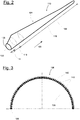
- FIG 2 shows an exemplary wind turbine rotor blade 110.
- the rotor blade 110 has the shape of a conventional rotor blade and has a rotor blade root region 114 which faces the rotor hub 112.
- the rotor blade root region 114 typically has a substantially circular cross section.
- the rotor blade root area 114 is followed by a transition area 116 and a profile area 118 of the Rotor blades 110.
- the rotor blade 110 has a pressure side 122 and an opposite suction side 124 with respect to a longitudinal extension direction 120.
- the interior of the rotor blade 110 is essentially hollow.
- a rotor blade connection 126 with a flange connection 128 is provided, by means of which the rotor blade 110 is mechanically connected to a pitch bearing or an extender.
- a flange insert 136 is provided, for example, as shown in FIG Figure 3 is shown.
- Figure 3 shows a partially circular segment of the flange insert 136 in a schematic cross-sectional view.
- the flange insert 136 has the flange connection 128 and is inserted as an insert into a production mold for producing the entire rotor blade 110.
- the structure comprises an inner laminate layer 138 and an outer laminate layer 140, which run in the manner of an arc of a circle and in which bearing sleeves 142 with an internal thread are embedded in the manner of an arc of a circle in the direction of longitudinal extent 120.
- the sleeves 142 are, for example, steel sleeves.
- Figure 4 shows schematically a partial sectional view through a flange connection 144 of two components 146 and 148 of a wind energy installation according to an exemplary embodiment of the invention.
- the first component 146 is a rotor blade 110, which has a flange connection 128 with bearing sleeves 142 - as described above and in FIG Fig. 3 shown - has.
- the second component 148 is an extender for connecting the rotor blade 110 to the rotor hub 112.
- the extender has a corresponding further flange connection 150.
- the bearing sleeves 142 each have a first bore 152.
- the further flange connection 150 points to the first bores 152 corresponding, aligned second bores 154, which are designed as through bores.
- Figure 4 shows the section through a pair of holes in both components.
- the two components 146, 148 are firmly connected to one another by means of bolts via the bores 152, 154.
- centering bolts 156 are used according to an exemplary embodiment of the invention, one of which is shown in FIG Figure 4 is shown. As described above, a centering bolt 156 is used to center the two components 146, 148 with respect to one another. After centering, the two components are firmly connected to one another via a large number of bearing bolts (not shown). Ultimately, the centering bolts 156 are removed again and replaced by further bearing bolts.
- Figure 5 shows a centering bolt 156 in isolation in a sectional view.
- centering bolt 156 and the flange connection 144 are described in detail below.
- the centering bolt 156 has a shaft 158 which extends along a longitudinal axis 160 from a first axial end 162 to a second axial end 164.
- the longitudinal axis 160 forms an axis of rotational symmetry.
- the shaft 158 is made of a steel material. Starting from the first end 162, the shaft 158 has along the Longitudinal axis 160 has a first section 166 with a first outside diameter 168, a second section 170 with a second outside diameter 172 and a third section 174 with a third outside diameter 176.
- the first section 166 has the first end 162 and the third section 174 has the second Late 164 on.
- the first outside diameter 168 is larger than the second outside diameter 172, which in turn is larger than the third outside diameter 176.
- the three sections 166, 170 and 174 are separated by shaft shoulders 180.
- the first section 166 has a first external thread 178.
- a one-piece centering sleeve 182 is pushed onto the second section 170 against the corresponding shaft shoulder 180.
- the centering sleeve 182 is made of bronze (a material with emergency running properties).
- the centering sleeve 182 is arranged on the shaft 158 so as to be rotatable about the longitudinal axis 160. For example, a clearance fit is provided.
- two spacer sleeves 184 are pushed onto the second section 170 against the centering sleeve. A throw fit is provided for this, for example.
- a securing sleeve 186 made of bronze (a material with emergency running properties) is screwed onto the third section 174.
- the securing sleeve 186 has an internal thread 188 which corresponds to a second external thread 190 of the third section 174 of the shaft 158. Both threads 188 and 190 are designed as left-hand threads.
- the securing sleeve 186 is screwed on, for example, against a stop on the shaft 156, for example an axial end of the second external thread 190.
- the securing sleeve 186 is designed and screwed onto the third section 174 such that the centering sleeve 182 is axially secured in a form-fitting manner with respect to the longitudinal axis 160 via the two spacer sleeves 184.
- the securing sleeve 186 also has a third external thread 192, by means of which the centering bolt 156 is screwed into the bearing sleeve 142, which has a corresponding second internal thread 192.
- the centering sleeve 182 has a sleeve outer diameter 196 which is greater than the outer diameters 168, 172, 176 and the outer diameters of the sleeves 184 and 186.
- the centering bolt 156 is designed such that with the flange connection 144 shown, i.e. when the two components 146, 148 are joined together, a fitting area 205 of the centering sleeve 182 is arranged in a flange area 198 of the two connected components 146 and 148.
- the flange area 198 means an axial area with respect to the longitudinal axis 160 around fitting surfaces 200 of the two assembled components 146 and 148.
- the two components 146, 148 are centered with respect to one another by means of the centering sleeve 182.
- the centering bolt 156 is firmly screwed and thus secured via a bolt nut, not shown, which is screwed onto the first section 166 from the side of the first axial end 162. All other centering bolts are mounted in the same way.
- FIG. 6 shows an enlarged sectional view through the centering sleeve 182.
- the centering sleeve 182 has the fitting area 205, which is arranged in the flange area 198 of the two connected components 146 and 148 in the assembled state of the centering bolt.
- the centering sleeve 182 has a on the outside circumferential first bevel 204, which gives the sleeve end 202 a conical shape.
- the centering sleeve 182 has a second bevel 208 running around the outside, which also gives the sleeve end 206 a conical shape.
- roundings can also be formed.
- the chamfers 204 and 208 facilitate the assembly and disassembly of the centering bolts 156.
- the first axial end 162 as in FIG Figure 5 can be seen to have a third bevel 210 for the same purposes.
- the second bevel 208 optionally serves as a stop element when the centering bolt 156 is screwed into the first bore 152, in which a corresponding counter bevel is located.
- the centering bolt 156 is only in contact with the securing sleeve 186 and with the bearing sleeve 142 via the second bevel 208.
- the centering bolt 156 in the flange area 198 is in contact with the bearing sleeve 142 only via the second bevel 208.
- the centering bolt 156 described enables the advantages and functions mentioned at the outset.
- the centering bolt 156 enables it to be removed again after all the bearing bolts have been screwed together. Details of the assembly or the production of the flange connection are illustrated using the schematic flow diagram of FIG Figure 7 explained.
- a first step S1 four of the centering bolts 156 described above are provided.
- the centering bolts 156 are mounted distributed uniformly over the circumference of the flange connection 128 of the first component 146.
- Centering bolt 156 is inserted into the corresponding bore 152 of a bearing sleeve 142 and screwed by means of the third external thread 192 of the securing sleeve 168.
- One or more centering bolts 156 can protrude with the first section 166 up to a part of the centering sleeve 182 from the corresponding bores 152.
- step S4 bearing bolts are screwed into the remaining first bores 152 in an analogous manner.
- the bearing bolts also protrude from the first bores 152, possibly not as far as the centering bolts 156.
- a next step S5 the two components 146, 148 are aligned with one another, so that the first bores 152 are arranged in alignment with the through bores 154 of the second component 148. This is done, for example, with the help of crane or lifting devices.
- a next step S6 the two components 146, 148 are joined together.
- the centering bolts 156 are first inserted into the corresponding bores due to their protrusion compared to the bearing bolts, so that a certain pre-centering takes place. Insertion is facilitated by the chamfers 210 on the first axial end 162 and the first chamfer 204. Then all the bearing bolts are inserted into the corresponding second bores 154.
- the components 146, 148 are joined together in a form-fitting manner, so that the mating surfaces 200 of the flange connections 128, 150 touch one another.
- the centering sleeves 182 are arranged in the flange region 198. As a result, the two components 146, 148 are centered with respect to one another.
- step S7 all centering bolts 156 and bearing bolts are secured with bolt nuts, so that the flange connection 144 is established. It can be advantageous to first secure the centering bolts 156 before the remaining bolts are secured.
- the centering bolts 156 are unlocked again, i.e. the bolt nuts are removed and the centering bolts 156 are dismantled.
- the centering bolts 156 are guided out of the bores 152, 154 from the side of the first axial end 162.
- the centering bolts 156 are rotated in order to loosen the screw connection in the bearing sleeve 142 and pulled out. Due to the structure described above, in particular the axial securing of the centering sleeve 182, the rotatability of the centering sleeve 182, the left-hand thread and the one-piece nature of the centering sleeve 182, the centering bolts 156 can be completely removed from the bores.
- bearing bolts are mounted in the bores previously occupied by centering bolts, so that the flange connection 144 is produced exclusively via the bearing bolts provided as intended.
- flange connection 144 is also suitable for other components of the wind energy installation, for example the connection of the two rotor blade segments 132, 134.
- the design of the centering bolt can also take place in the opposite direction with respect to the longitudinal axis 160 and the assembly is thus also changed.
- the centering bolt 156 is designed such that it is screwed with the first end 162 into the bearing sleeve 142 of the first component 146.
- the first section 166 of the shaft 158 is assigned to the bearing sleeve 140 and has an external thread for screwing into the bearing sleeve 142.
- the second section 170 with a reduced diameter and with the centering sleeve 182 pushed on.
- the centering sleeve 182 is again axially secured, for example by means of a securing sleeve 186 which is screwed onto the second or a third section 170, 174 of the shaft 158.
- Spacer sleeves 184 can, but do not have to be, arranged between securing sleeve 186 and centering sleeve 182.
- the second or third section 170, 174 has an external thread which protrudes from the second component 148 and via which the centering bolt 154 is secured on the second component 148, in particular by means of a bolt nut.
Landscapes
- Engineering & Computer Science (AREA)
- General Engineering & Computer Science (AREA)
- Mechanical Engineering (AREA)
- Life Sciences & Earth Sciences (AREA)
- Sustainable Development (AREA)
- Sustainable Energy (AREA)
- Chemical & Material Sciences (AREA)
- Combustion & Propulsion (AREA)
- Wind Motors (AREA)
Claims (15)
- Boulon de centrage (156) destiné à la réalisation d'une connexion à bride (144) entre deux composants (146, 148) d'une éolienne (100), en particulier entre une pale de rotor (110) et un moyeu de rotor (112) ou entre un arbre de rotor et un moyeu de rotor (112), présentant- un fût (158), sachant que le fût (158)- présente un axe longitudinal (160), et- présente le long de l'axe longitudinal (160) un premier tronçon (166) d'un premier diamètre extérieur (168) et un deuxième tronçon (170) consécutif au premier tronçon (166), qui présente un deuxième diamètre extérieur (172) plus petit en comparaison avec le premier diamètre extérieur (168),- une douille de centrage (182) qui est emmanchée sur le deuxième tronçon (170) du fût (158), sachant que la douille de centrage (182)sachant que le boulon de centrage (156) est constitué pour être monté, pour la réalisation de la connexion à bride (144), dans deux alésages (152, 154) en alignement l'un par rapport à l'autre de raccords à bride (128, 150) des deux composants (146, 148) à relier de telle manière que la douille de centrage (182) soit disposée dans les deux alésages (152, 154) en alignement pour le centrage des composants (146, 148).- est logée sur le fût (158) de manière rotative autour de l'axe longitudinal (160),- est arrêtée axialement par rapport à l'axe longitudinal (160) contre toute translation, et- présente un diamètre extérieur de douille (196) qui est plus grand que le premier diamètre extérieur (168),
- Boulon de centrage (156) selon la revendication 1, sachant que la douille de centrage (182) est arrêtée par adhérence de forme sur le fût (158) axialement par rapport à l'axe longitudinal (160) moyennant une bague d'arrêt.
- Boulon de centrage (156) selon la revendication 1 ou 2, sachant que la douille de centrage (182) est arrêtée par adhérence de forme sur le fût (158) axialement par rapport à l'axe longitudinal (160) moyennant une douille d'arrêt (186).
- Boulon de centrage (156) selon la revendication 2 ou 3, sachant qu'encore une ou plusieurs douilles d'entretoise (184) qui sont emmanchées sur le fût (158) sont disposées entre la douille d'arrêt (186) ou la bague d'arrêt et la douille de centrage (182).
- Boulon de centrage (156) selon la revendication 3 ou 4, sachant que la douille d'arrêt (186) est vissée sur le fût (158) .
- Boulon de centrage (156) selon l'une des revendications 3 à 5, sachant que la douille d'arrêt (186) est vissée sur un troisième tronçon (174) du fût (158) qui est disposé consécutivement au premier et au deuxième tronçon (166, 170) et présente un troisième diamètre extérieur (176) qui est plus petit que le deuxième diamètre extérieur (172).
- Boulon de centrage (156) selon l'une des revendications 3 à 6, sachant que la douille d'arrêt (186) présente un filetage extérieur (192) destiné à être vissé dans un filetage intérieur (194) de l'un des deux composants (146, 148) .
- Boulon de centrage (156) selon l'une des revendications 3 à 7, sachant que la douille d'arrêt (186) présente un matériau qui garantit des propriétés de fonctionnement d'urgence.
- Boulon de centrage (156) selon l'une des revendications précédentes, sachant que la douille de centrage (182) présente un premier tronçon à terminaison conique ou un premier chanfrein (204) par rapport à l'axe longitudinal (160) au niveau d'une extrémité (202) axiale tournée vers le premier tronçon (166).
- Boulon de centrage (156) selon l'une des revendications précédentes, sachant que la douille de centrage (182) présente un deuxième tronçon à terminaison conique ou un deuxième chanfrein (208) par rapport à l'axe longitudinal (160) au niveau d'une extrémité (206) axiale opposée au premier tronçon (166).
- Boulon de centrage (156) selon la revendication 10, sachant que le deuxième chanfrein (208) sert de face de butée lors du montage dans un alésage (152) d'un des deux composants (146, 148).
- Boulon de centrage (156) selon l'une des revendications précédentes, sachant que la douille de centrage (182) présente un matériau de glissement qui garantit des propriétés de fonctionnement d'urgence.
- Procédé destiné à la réalisation d'une connexion à bride (144) entre deux composants (146, 148) d'une éolienne (100), en particulier entre une pale de rotor (110) et un moyeu de rotor (112) ou entre un arbre de rotor et un moyeu de rotor (112), présentant les étapes :- mise à disposition d'un boulon de centrage (156) selon l'une des revendications 1 à 12,- mise à disposition d'une pluralité de boulons de palier,- montage du boulon de centrage (156) dans un alésage (152) correspondant d'un raccord à bride (128) du premier composant (146) de telle sorte que celui-ci dépasse des alésages (152) correspondants,- montage de la pluralité de boulons de palier dans des alésages (152) correspondants du raccord à bride (150) du premier composant (146) de telle sorte que ceux-ci dépassent des alésages (152) correspondants,- orientation des deux composants (146, 148) de telle manière que les alésages (152) du raccord à bride (128) du premier composant (146) et des alésages (154) d'un raccord à bride (150) du deuxième composant (148) soient disposés en alignement les uns par rapport aux autres,- assemblage des deux composants (146, 148) et insertion de tous les boulons montés dans les alésages (154) correspondants du raccord à bride (150) du deuxième composant (148) de telle sorte que la douille de centrage (182) du boulon de centrage (156) soit disposée dans deux alésages (152, 154) correspondants en alignement l'un par rapport à l'autre et de ce fait les deux composants (146, 148) soient centrés l'un par rapport à l'autre ;- arrêt du boulon de centrage (156) et des boulons de palier pour la réalisation de la connexion à bride (144).
- Procédé selon la revendication 13, sachant que le boulon de centrage (156) est démonté hors des alésages (152, 154) et remplacé par un boulon de palier après la réalisation de la connexion à bride (144).
- Connexion à bride (144) entre deux composants (146, 148) d'une éolienne (100), en particulier entre une pale de rotor (110) et un moyeu de rotor (112) ou entre un arbre de rotor et un moyeu de rotor (112), sachant que- chaque composant (146, 148) présente un raccord à bride (128, 150) présentant plusieurs alésages (152, 154),- les composants (146, 148) sont disposés l'un contre l'autre et reliés de telle sorte que les alésages (152, 154) soient en alignement les uns par rapport aux autres,- sachant qu'un ou plusieurs boulons de centrage (156) selon l'une des revendications 1 à 12 sont montés dans respectivement deux alésages (152, 154) en alignement l'un par rapport à l'autre des raccords à bride (128, 150) des deux composants (146, 148) de telle sorte que chaque douille de centrage (182) d'un boulon de centrage (156) soit disposée dans les respectivement deux alésages (152, 154) en alignement pour le centrage des composants (146, 148).
Priority Applications (3)
| Application Number | Priority Date | Filing Date | Title |
|---|---|---|---|
| DK18207201.7T DK3657012T3 (da) | 2018-11-20 | 2018-11-20 | Centreringsbolt til fremstilling af en flangeforbindelse mellem to komponenter af et vindenergianlæg, fremgangsmåde til fremstilling af en flangeforbindelse og en flangeforbindelse |
| EP18207201.7A EP3657012B1 (fr) | 2018-11-20 | 2018-11-20 | Boulons de centrage destinés à la fabrication d'un raccordement à bride entre deux composants d'une éolienne, procédé de fabrication d'un raccordement à bride ainsi que raccordement à bride |
| ES18207201T ES2886879T3 (es) | 2018-11-20 | 2018-11-20 | Perno de centraje para producir una unión abridada entre dos piezas constructivas de un aerogenerador, procedimiento para producir una unión abridada, así como unión abridada |
Applications Claiming Priority (1)
| Application Number | Priority Date | Filing Date | Title |
|---|---|---|---|
| EP18207201.7A EP3657012B1 (fr) | 2018-11-20 | 2018-11-20 | Boulons de centrage destinés à la fabrication d'un raccordement à bride entre deux composants d'une éolienne, procédé de fabrication d'un raccordement à bride ainsi que raccordement à bride |
Publications (2)
| Publication Number | Publication Date |
|---|---|
| EP3657012A1 EP3657012A1 (fr) | 2020-05-27 |
| EP3657012B1 true EP3657012B1 (fr) | 2021-06-02 |
Family
ID=64402051
Family Applications (1)
| Application Number | Title | Priority Date | Filing Date |
|---|---|---|---|
| EP18207201.7A Active EP3657012B1 (fr) | 2018-11-20 | 2018-11-20 | Boulons de centrage destinés à la fabrication d'un raccordement à bride entre deux composants d'une éolienne, procédé de fabrication d'un raccordement à bride ainsi que raccordement à bride |
Country Status (3)
| Country | Link |
|---|---|
| EP (1) | EP3657012B1 (fr) |
| DK (1) | DK3657012T3 (fr) |
| ES (1) | ES2886879T3 (fr) |
Cited By (1)
| Publication number | Priority date | Publication date | Assignee | Title |
|---|---|---|---|---|
| WO2026012555A1 (fr) * | 2024-07-09 | 2026-01-15 | Vestas Wind Systems A/S | Manchon de centrage, élément de fixation de centrage, pale de rotor d'une éolienne et procédé de montage d'une pale de rotor sur un moyeu d'une éolienne |
Families Citing this family (3)
| Publication number | Priority date | Publication date | Assignee | Title |
|---|---|---|---|---|
| WO2021063495A1 (fr) * | 2019-10-02 | 2021-04-08 | Nordex Energy Se & Co. Kg | Pale de rotor d'éolienne, manchon de montage et procédé de liaison de deux segments de pale de rotor |
| EP4239186B1 (fr) * | 2022-03-02 | 2025-10-22 | LM Wind Power A/S | Ensemble dispositif de fixation, ensemble moyeu d'éolienne et procédés associés |
| CN115788764B (zh) * | 2022-11-30 | 2026-03-20 | 三一重能股份有限公司 | 叶片叶根的连接结构、风力发电机及风电叶片的生产方法 |
Family Cites Families (5)
| Publication number | Priority date | Publication date | Assignee | Title |
|---|---|---|---|---|
| KR101345716B1 (ko) * | 2012-09-07 | 2013-12-27 | 삼성중공업 주식회사 | 풍력발전기용 결합 보조 장치 및 이에 의한 결합 방법 |
| GB201402830D0 (en) | 2014-02-18 | 2014-04-02 | Lm Wp Patent Holding As | Wind turbine blade brushing system |
| CN205243733U (zh) * | 2015-12-18 | 2016-05-18 | 新疆金风科技股份有限公司 | 叶片导正装置及风力发电机组 |
| DE102016000291A1 (de) * | 2016-01-15 | 2017-07-20 | Senvion Gmbh | Verfahren zum Herstellen einer Flanschverbindung, Verwendung, Flanschverbindung und Windenergieanlage |
| CN106640903B (zh) * | 2016-12-23 | 2019-06-21 | 北京金风科创风电设备有限公司 | 定心紧固件、其制作方法、使用方法及风力发电机组 |
-
2018
- 2018-11-20 ES ES18207201T patent/ES2886879T3/es active Active
- 2018-11-20 DK DK18207201.7T patent/DK3657012T3/da active
- 2018-11-20 EP EP18207201.7A patent/EP3657012B1/fr active Active
Cited By (1)
| Publication number | Priority date | Publication date | Assignee | Title |
|---|---|---|---|---|
| WO2026012555A1 (fr) * | 2024-07-09 | 2026-01-15 | Vestas Wind Systems A/S | Manchon de centrage, élément de fixation de centrage, pale de rotor d'une éolienne et procédé de montage d'une pale de rotor sur un moyeu d'une éolienne |
Also Published As
| Publication number | Publication date |
|---|---|
| DK3657012T3 (da) | 2021-09-06 |
| ES2886879T3 (es) | 2021-12-21 |
| EP3657012A1 (fr) | 2020-05-27 |
Similar Documents
| Publication | Publication Date | Title |
|---|---|---|
| EP4038271B1 (fr) | Pale de rotor d'éolienne et procédé de liaison de deux segments de pale de rotor | |
| EP1975405B1 (fr) | Raccordement des éléments d'une installation d'énergie éolienne, utilization et procédé | |
| EP1398499B1 (fr) | Fixation des aubes sur le moyeu d'éolienne | |
| EP3469212B1 (fr) | Rotor pour éolienne, pale de rotor pour éolienne, manchon et procédé de montage d'un rotor | |
| EP2154367B1 (fr) | Procédé de montage d'un moyeu d'hélice sur un arbre de rotor d'une éolienne et éolienne | |
| EP3657012A1 (fr) | Boulons de centrage destinés à la fabrication d'un raccordement à bride entre deux composants d'une éolienne, procédé de fabrication d'un raccordement à bride ainsi que raccordement à bride | |
| EP2882962B1 (fr) | Arbre de rotor destiné à une turbine éolienne | |
| EP3929431B1 (fr) | Module et procédé de raccordement de deux segments de pale de rotor d'une pale de rotor d'éolienne | |
| DE102017106875B4 (de) | Windkraftanlage und Verfahren zu dessen Montage | |
| EP3557041B1 (fr) | Manchon pour une pale de rotor d'éolienne, tambour bridé, pale de rotor d'éolienne et éolienne | |
| EP4155530B1 (fr) | Pale de rotor pour éolienne | |
| DE10160022A1 (de) | Verfahren zum Herstellen eines Turms einer Windkraftanlage, mit diesem Verfahren hergestellter Turm und Bauelemente zur Herstellung eines Turms | |
| EP3333439A1 (fr) | Procédé de remplacement du palier usé, en particulier de remplacement du palier de grand diamètre comme palier principal d'une éolienne et dispositif de palier | |
| DE102006031174B3 (de) | Rotornabe einer Windenergieanlage | |
| EP4062078B1 (fr) | Agencement de palier et procédé de fabrication dudit type d'agencement de palier | |
| EP4490411B1 (fr) | Dispositif de palier réglable, en particulier pour éoliennes | |
| DE102016123346B3 (de) | Faserverbundbauteil, Faserverbundstruktur und Herstellung derselben | |
| EP3561292B1 (fr) | Boulons filetés de fixation pour la production d'un raccord à bride d'une pale de rotor d'une éolienne, système, procédé, insert à bride, pale de rotor ainsi qu'éolienne | |
| EP3276197A1 (fr) | Dispositif de fixation de palier pour un palier monté en rotation sur un arbre | |
| EP1367273A2 (fr) | Palier lisse pour charges radiales et axiales | |
| EP2593691B1 (fr) | Arbre pour turbomachine | |
| DE102024209977A1 (de) | Getriebeanordnung und Windkraftanlage | |
| WO2020058104A1 (fr) | Système de palier de pale pour une éolienne, éolienne et procédé de fabrication d'un système de palier de pale | |
| BE1029770B1 (de) | Rotorlagereinheit für eine Windenergieanlage und Verfahren zur Einstellung der Vorspannung in einer Rotorlagereinheit | |
| EP4400713A1 (fr) | Pale de rotor d'éolienne divisée et procédé de liaison de deux segments de pale de rotor d'une pale de rotor d'éolienne |
Legal Events
| Date | Code | Title | Description |
|---|---|---|---|
| PUAI | Public reference made under article 153(3) epc to a published international application that has entered the european phase |
Free format text: ORIGINAL CODE: 0009012 |
|
| STAA | Information on the status of an ep patent application or granted ep patent |
Free format text: STATUS: THE APPLICATION HAS BEEN PUBLISHED |
|
| AK | Designated contracting states |
Kind code of ref document: A1 Designated state(s): AL AT BE BG CH CY CZ DE DK EE ES FI FR GB GR HR HU IE IS IT LI LT LU LV MC MK MT NL NO PL PT RO RS SE SI SK SM TR |
|
| AX | Request for extension of the european patent |
Extension state: BA ME |
|
| STAA | Information on the status of an ep patent application or granted ep patent |
Free format text: STATUS: REQUEST FOR EXAMINATION WAS MADE |
|
| 17P | Request for examination filed |
Effective date: 20201116 |
|
| RBV | Designated contracting states (corrected) |
Designated state(s): AL AT BE BG CH CY CZ DE DK EE ES FI FR GB GR HR HU IE IS IT LI LT LU LV MC MK MT NL NO PL PT RO RS SE SI SK SM TR |
|
| RIC1 | Information provided on ipc code assigned before grant |
Ipc: F03D 13/10 20160101ALI20201202BHEP Ipc: F16B 5/02 20060101ALI20201202BHEP Ipc: F03D 15/00 20160101ALI20201202BHEP Ipc: F16B 35/02 20060101ALI20201202BHEP Ipc: F03D 13/20 20160101ALI20201202BHEP Ipc: F03D 80/00 20160101ALI20201202BHEP Ipc: F16B 19/02 20060101ALI20201202BHEP Ipc: F16B 7/18 20060101ALI20201202BHEP Ipc: F03D 1/06 20060101AFI20201202BHEP Ipc: F16B 35/00 20060101ALI20201202BHEP |
|
| GRAP | Despatch of communication of intention to grant a patent |
Free format text: ORIGINAL CODE: EPIDOSNIGR1 |
|
| STAA | Information on the status of an ep patent application or granted ep patent |
Free format text: STATUS: GRANT OF PATENT IS INTENDED |
|
| INTG | Intention to grant announced |
Effective date: 20210112 |
|
| RAP3 | Party data changed (applicant data changed or rights of an application transferred) |
Owner name: NORDEX ENERGY SE & CO. KG |
|
| GRAS | Grant fee paid |
Free format text: ORIGINAL CODE: EPIDOSNIGR3 |
|
| GRAA | (expected) grant |
Free format text: ORIGINAL CODE: 0009210 |
|
| STAA | Information on the status of an ep patent application or granted ep patent |
Free format text: STATUS: THE PATENT HAS BEEN GRANTED |
|
| REG | Reference to a national code |
Ref country code: CH Ref legal event code: EP |
|
| AK | Designated contracting states |
Kind code of ref document: B1 Designated state(s): AL AT BE BG CH CY CZ DE DK EE ES FI FR GB GR HR HU IE IS IT LI LT LU LV MC MK MT NL NO PL PT RO RS SE SI SK SM TR |
|
| REG | Reference to a national code |
Ref country code: GB Ref legal event code: FG4D Free format text: NOT ENGLISH |
|
| REG | Reference to a national code |
Ref country code: AT Ref legal event code: REF Ref document number: 1398671 Country of ref document: AT Kind code of ref document: T Effective date: 20210615 |
|
| REG | Reference to a national code |
Ref country code: IE Ref legal event code: FG4D Free format text: LANGUAGE OF EP DOCUMENT: GERMAN |
|
| REG | Reference to a national code |
Ref country code: DE Ref legal event code: R096 Ref document number: 502018005507 Country of ref document: DE |
|
| REG | Reference to a national code |
Ref country code: DK Ref legal event code: T3 Effective date: 20210831 |
|
| REG | Reference to a national code |
Ref country code: LT Ref legal event code: MG9D |
|
| PG25 | Lapsed in a contracting state [announced via postgrant information from national office to epo] |
Ref country code: BG Free format text: LAPSE BECAUSE OF FAILURE TO SUBMIT A TRANSLATION OF THE DESCRIPTION OR TO PAY THE FEE WITHIN THE PRESCRIBED TIME-LIMIT Effective date: 20210902 Ref country code: FI Free format text: LAPSE BECAUSE OF FAILURE TO SUBMIT A TRANSLATION OF THE DESCRIPTION OR TO PAY THE FEE WITHIN THE PRESCRIBED TIME-LIMIT Effective date: 20210602 Ref country code: HR Free format text: LAPSE BECAUSE OF FAILURE TO SUBMIT A TRANSLATION OF THE DESCRIPTION OR TO PAY THE FEE WITHIN THE PRESCRIBED TIME-LIMIT Effective date: 20210602 Ref country code: LT Free format text: LAPSE BECAUSE OF FAILURE TO SUBMIT A TRANSLATION OF THE DESCRIPTION OR TO PAY THE FEE WITHIN THE PRESCRIBED TIME-LIMIT Effective date: 20210602 |
|
| PG25 | Lapsed in a contracting state [announced via postgrant information from national office to epo] |
Ref country code: GR Free format text: LAPSE BECAUSE OF FAILURE TO SUBMIT A TRANSLATION OF THE DESCRIPTION OR TO PAY THE FEE WITHIN THE PRESCRIBED TIME-LIMIT Effective date: 20210903 Ref country code: PL Free format text: LAPSE BECAUSE OF FAILURE TO SUBMIT A TRANSLATION OF THE DESCRIPTION OR TO PAY THE FEE WITHIN THE PRESCRIBED TIME-LIMIT Effective date: 20210602 Ref country code: NO Free format text: LAPSE BECAUSE OF FAILURE TO SUBMIT A TRANSLATION OF THE DESCRIPTION OR TO PAY THE FEE WITHIN THE PRESCRIBED TIME-LIMIT Effective date: 20210902 Ref country code: LV Free format text: LAPSE BECAUSE OF FAILURE TO SUBMIT A TRANSLATION OF THE DESCRIPTION OR TO PAY THE FEE WITHIN THE PRESCRIBED TIME-LIMIT Effective date: 20210602 Ref country code: RS Free format text: LAPSE BECAUSE OF FAILURE TO SUBMIT A TRANSLATION OF THE DESCRIPTION OR TO PAY THE FEE WITHIN THE PRESCRIBED TIME-LIMIT Effective date: 20210602 Ref country code: SE Free format text: LAPSE BECAUSE OF FAILURE TO SUBMIT A TRANSLATION OF THE DESCRIPTION OR TO PAY THE FEE WITHIN THE PRESCRIBED TIME-LIMIT Effective date: 20210602 |
|
| REG | Reference to a national code |
Ref country code: ES Ref legal event code: FG2A Ref document number: 2886879 Country of ref document: ES Kind code of ref document: T3 Effective date: 20211221 |
|
| PG25 | Lapsed in a contracting state [announced via postgrant information from national office to epo] |
Ref country code: EE Free format text: LAPSE BECAUSE OF FAILURE TO SUBMIT A TRANSLATION OF THE DESCRIPTION OR TO PAY THE FEE WITHIN THE PRESCRIBED TIME-LIMIT Effective date: 20210602 Ref country code: SK Free format text: LAPSE BECAUSE OF FAILURE TO SUBMIT A TRANSLATION OF THE DESCRIPTION OR TO PAY THE FEE WITHIN THE PRESCRIBED TIME-LIMIT Effective date: 20210602 Ref country code: SM Free format text: LAPSE BECAUSE OF FAILURE TO SUBMIT A TRANSLATION OF THE DESCRIPTION OR TO PAY THE FEE WITHIN THE PRESCRIBED TIME-LIMIT Effective date: 20210602 Ref country code: CZ Free format text: LAPSE BECAUSE OF FAILURE TO SUBMIT A TRANSLATION OF THE DESCRIPTION OR TO PAY THE FEE WITHIN THE PRESCRIBED TIME-LIMIT Effective date: 20210602 Ref country code: RO Free format text: LAPSE BECAUSE OF FAILURE TO SUBMIT A TRANSLATION OF THE DESCRIPTION OR TO PAY THE FEE WITHIN THE PRESCRIBED TIME-LIMIT Effective date: 20210602 Ref country code: NL Free format text: LAPSE BECAUSE OF FAILURE TO SUBMIT A TRANSLATION OF THE DESCRIPTION OR TO PAY THE FEE WITHIN THE PRESCRIBED TIME-LIMIT Effective date: 20210602 Ref country code: PT Free format text: LAPSE BECAUSE OF FAILURE TO SUBMIT A TRANSLATION OF THE DESCRIPTION OR TO PAY THE FEE WITHIN THE PRESCRIBED TIME-LIMIT Effective date: 20211004 |
|
| REG | Reference to a national code |
Ref country code: DE Ref legal event code: R097 Ref document number: 502018005507 Country of ref document: DE |
|
| PLBE | No opposition filed within time limit |
Free format text: ORIGINAL CODE: 0009261 |
|
| STAA | Information on the status of an ep patent application or granted ep patent |
Free format text: STATUS: NO OPPOSITION FILED WITHIN TIME LIMIT |
|
| 26N | No opposition filed |
Effective date: 20220303 |
|
| PG25 | Lapsed in a contracting state [announced via postgrant information from national office to epo] |
Ref country code: AL Free format text: LAPSE BECAUSE OF FAILURE TO SUBMIT A TRANSLATION OF THE DESCRIPTION OR TO PAY THE FEE WITHIN THE PRESCRIBED TIME-LIMIT Effective date: 20210602 |
|
| PG25 | Lapsed in a contracting state [announced via postgrant information from national office to epo] |
Ref country code: MC Free format text: LAPSE BECAUSE OF FAILURE TO SUBMIT A TRANSLATION OF THE DESCRIPTION OR TO PAY THE FEE WITHIN THE PRESCRIBED TIME-LIMIT Effective date: 20210602 |
|
| REG | Reference to a national code |
Ref country code: CH Ref legal event code: PL |
|
| PG25 | Lapsed in a contracting state [announced via postgrant information from national office to epo] |
Ref country code: LU Free format text: LAPSE BECAUSE OF NON-PAYMENT OF DUE FEES Effective date: 20211120 Ref country code: IT Free format text: LAPSE BECAUSE OF FAILURE TO SUBMIT A TRANSLATION OF THE DESCRIPTION OR TO PAY THE FEE WITHIN THE PRESCRIBED TIME-LIMIT Effective date: 20210602 Ref country code: BE Free format text: LAPSE BECAUSE OF NON-PAYMENT OF DUE FEES Effective date: 20211130 |
|
| REG | Reference to a national code |
Ref country code: BE Ref legal event code: MM Effective date: 20211130 |
|
| PG25 | Lapsed in a contracting state [announced via postgrant information from national office to epo] |
Ref country code: IE Free format text: LAPSE BECAUSE OF NON-PAYMENT OF DUE FEES Effective date: 20211120 |
|
| PG25 | Lapsed in a contracting state [announced via postgrant information from national office to epo] |
Ref country code: FR Free format text: LAPSE BECAUSE OF NON-PAYMENT OF DUE FEES Effective date: 20211130 |
|
| P01 | Opt-out of the competence of the unified patent court (upc) registered |
Effective date: 20230515 |
|
| PG25 | Lapsed in a contracting state [announced via postgrant information from national office to epo] |
Ref country code: CY Free format text: LAPSE BECAUSE OF FAILURE TO SUBMIT A TRANSLATION OF THE DESCRIPTION OR TO PAY THE FEE WITHIN THE PRESCRIBED TIME-LIMIT Effective date: 20210602 |
|
| GBPC | Gb: european patent ceased through non-payment of renewal fee |
Effective date: 20221120 |
|
| PG25 | Lapsed in a contracting state [announced via postgrant information from national office to epo] |
Ref country code: LI Free format text: LAPSE BECAUSE OF NON-PAYMENT OF DUE FEES Effective date: 20220630 Ref country code: HU Free format text: LAPSE BECAUSE OF FAILURE TO SUBMIT A TRANSLATION OF THE DESCRIPTION OR TO PAY THE FEE WITHIN THE PRESCRIBED TIME-LIMIT; INVALID AB INITIO Effective date: 20181120 Ref country code: CH Free format text: LAPSE BECAUSE OF NON-PAYMENT OF DUE FEES Effective date: 20220630 |
|
| PG25 | Lapsed in a contracting state [announced via postgrant information from national office to epo] |
Ref country code: GB Free format text: LAPSE BECAUSE OF NON-PAYMENT OF DUE FEES Effective date: 20221120 |
|
| PG25 | Lapsed in a contracting state [announced via postgrant information from national office to epo] |
Ref country code: MK Free format text: LAPSE BECAUSE OF FAILURE TO SUBMIT A TRANSLATION OF THE DESCRIPTION OR TO PAY THE FEE WITHIN THE PRESCRIBED TIME-LIMIT Effective date: 20210602 |
|
| PG25 | Lapsed in a contracting state [announced via postgrant information from national office to epo] |
Ref country code: TR Free format text: LAPSE BECAUSE OF FAILURE TO SUBMIT A TRANSLATION OF THE DESCRIPTION OR TO PAY THE FEE WITHIN THE PRESCRIBED TIME-LIMIT Effective date: 20210602 |
|
| PG25 | Lapsed in a contracting state [announced via postgrant information from national office to epo] |
Ref country code: MT Free format text: LAPSE BECAUSE OF FAILURE TO SUBMIT A TRANSLATION OF THE DESCRIPTION OR TO PAY THE FEE WITHIN THE PRESCRIBED TIME-LIMIT Effective date: 20210602 |
|
| REG | Reference to a national code |
Ref country code: AT Ref legal event code: MM01 Ref document number: 1398671 Country of ref document: AT Kind code of ref document: T Effective date: 20231120 |
|
| PG25 | Lapsed in a contracting state [announced via postgrant information from national office to epo] |
Ref country code: AT Free format text: LAPSE BECAUSE OF NON-PAYMENT OF DUE FEES Effective date: 20231120 |
|
| PG25 | Lapsed in a contracting state [announced via postgrant information from national office to epo] |
Ref country code: AT Free format text: LAPSE BECAUSE OF NON-PAYMENT OF DUE FEES Effective date: 20231120 |
|
| PGFP | Annual fee paid to national office [announced via postgrant information from national office to epo] |
Ref country code: DE Payment date: 20251118 Year of fee payment: 8 |
|
| PGFP | Annual fee paid to national office [announced via postgrant information from national office to epo] |
Ref country code: DK Payment date: 20251119 Year of fee payment: 8 |
|
| PGFP | Annual fee paid to national office [announced via postgrant information from national office to epo] |
Ref country code: ES Payment date: 20251216 Year of fee payment: 8 |
|
| PGFP | Annual fee paid to national office [announced via postgrant information from national office to epo] |
Ref country code: AT Payment date: 20260410 Year of fee payment: 5 |