EP3660241A1 - Kopplungseinheit für paneele - Google Patents
Kopplungseinheit für paneele Download PDFInfo
- Publication number
- EP3660241A1 EP3660241A1 EP19212439.4A EP19212439A EP3660241A1 EP 3660241 A1 EP3660241 A1 EP 3660241A1 EP 19212439 A EP19212439 A EP 19212439A EP 3660241 A1 EP3660241 A1 EP 3660241A1
- Authority
- EP
- European Patent Office
- Prior art keywords
- base body
- coupling unit
- retention
- extended
- panel
- Prior art date
- Legal status (The legal status is an assumption and is not a legal conclusion. Google has not performed a legal analysis and makes no representation as to the accuracy of the status listed.)
- Granted
Links
Images









Classifications
-
- E—FIXED CONSTRUCTIONS
- E04—BUILDING
- E04F—FINISHING WORK ON BUILDINGS, e.g. STAIRS, FLOORS
- E04F15/00—Flooring
- E04F15/02—Flooring or floor layers composed of a number of similar elements
- E04F15/02044—Separate elements for fastening to an underlayer
-
- E—FIXED CONSTRUCTIONS
- E04—BUILDING
- E04F—FINISHING WORK ON BUILDINGS, e.g. STAIRS, FLOORS
- E04F15/00—Flooring
- E04F15/02—Flooring or floor layers composed of a number of similar elements
- E04F15/02177—Floor elements for use at a specific location
- E04F15/02183—Floor elements for use at a specific location for outdoor use, e.g. in decks, patios, terraces, verandas or the like
-
- E—FIXED CONSTRUCTIONS
- E04—BUILDING
- E04F—FINISHING WORK ON BUILDINGS, e.g. STAIRS, FLOORS
- E04F15/00—Flooring
- E04F15/02—Flooring or floor layers composed of a number of similar elements
- E04F15/02044—Separate elements for fastening to an underlayer
- E04F2015/0205—Separate elements for fastening to an underlayer with load-supporting elongated furring elements between the flooring elements and the underlayer
- E04F2015/02066—Separate elements for fastening to an underlayer with load-supporting elongated furring elements between the flooring elements and the underlayer with additional fastening elements between furring elements and flooring elements
- E04F2015/02077—Separate elements for fastening to an underlayer with load-supporting elongated furring elements between the flooring elements and the underlayer with additional fastening elements between furring elements and flooring elements the additional fastening elements located in-between two adjacent flooring elements
- E04F2015/02094—Engaging side grooves running along the whole length of the flooring elements
-
- E—FIXED CONSTRUCTIONS
- E04—BUILDING
- E04F—FINISHING WORK ON BUILDINGS, e.g. STAIRS, FLOORS
- E04F2201/00—Joining sheets or plates or panels
- E04F2201/05—Separate connectors or inserts, e.g. pegs, pins, keys or strips
-
- E—FIXED CONSTRUCTIONS
- E04—BUILDING
- E04F—FINISHING WORK ON BUILDINGS, e.g. STAIRS, FLOORS
- E04F2201/00—Joining sheets or plates or panels
- E04F2201/05—Separate connectors or inserts, e.g. pegs, pins, keys or strips
- E04F2201/0505—Pegs or pins
-
- E—FIXED CONSTRUCTIONS
- E04—BUILDING
- E04F—FINISHING WORK ON BUILDINGS, e.g. STAIRS, FLOORS
- E04F2201/00—Joining sheets or plates or panels
- E04F2201/05—Separate connectors or inserts, e.g. pegs, pins, keys or strips
- E04F2201/0517—U- or C-shaped brackets and clamps
Definitions
- the present invention refers to a coupling unit for panels, according to the preamble of the independent claim No. 1.
- the present coupling unit is intended to be advantageously employed for fixing panels (such as boards or strips) to a support under-structure, in particular for attaining flooring (such as strip-like foundations, parquet for outdoor settings, decking, etc.) or for attaining facade cladding, both for external and internal settings.
- panels such as boards or strips
- flooring such as strip-like foundations, parquet for outdoor settings, decking, etc.
- facade cladding both for external and internal settings.
- the present coupling unit is inserted in the field of production of fixing systems (in particular carpentry components) for making cladding by means of panels of any material (such as wood, synthetic material, WPC, metal material, etc.).
- the typical structure of a strip-like foundation or of a panel cladding comprises a load-bearing under-structure (also termed nailing/gluing strip in the jargon of the field) constituted by a framework of different materials (such as wood, metal, synthetic material) intended to be abutted against the ground or anchored to the wall to be clad.
- a load-bearing under-structure also termed nailing/gluing strip in the jargon of the field
- a series of side-by-side covering panels are fixed, which constitute the treadable surface of the floor or the facade cladding.
- the covering panels are fixed by means of coupling systems which retain each strip rigidly fixed to the load-bearing under-structure.
- One of such coupling systems of known type provides for anchoring the panels to the load-bearing under-structure by means of a fitted connection.
- appendages or engagement teeth are made which are adapted to be engaged on corresponding notches or grooves made on the panels, and shaped with geometry such to retain the panels to the load-bearing under-structure without requiring further engagement elements.
- Such coupling system of known type complicates the removal of a panel from the under-structure (e.g. in order to substitute it) and it is subject, especially as time progresses, to forming loosening between the panel and the load-bearing under-structure.
- Coupling systems are also known which provide for simply abutting the panels against the load-bearing under-structure and fixing them by means of screws or nails which transversely perforate the panels up to being engaged in the load-bearing under-structure.
- the latter system of known type even if it is structurally simple and allows easily removing each single panel, has the disadvantage of subjecting the panels to greater stresses and of having to apply screws or nails to the panels which remain visible, deteriorating the aesthetic appearance of the floor or cladding.
- coupling systems have been introduced on the market which provide for anchoring the panels to the load-bearing under-structure by means of hooked plates which engage suitable longitudinal grooves made in the thickness of the sides of the panels.
- a first type of the latter coupling systems (an example of which is described in the patent application US 2009/0019805 ) comprises multiple plates that are substantially T-shaped, each provided with a stem intended to be fixed to the load-bearing under-structure and with two opposite lateral wings intended to be engaged in the longitudinal grooves of two corresponding adjacent sides of two side-by-side panels.
- the stem of each shaped plate is provided with a through hole in which a screw, a nail or a pin is inserted which is adapted to retain the shaped plate to the under-structure.
- a further drawback is due to the fact that the lateral wings of each shaped plate can be arranged at a single fixed distance from the under-structure (given for example by the length of the stem). Since, in the market, multiple types of panels are present with different thicknesses and with longitudinal grooves in different positions from the panel faces, it is necessary to arrange different specific shaped plates for each panel type.
- a coupling system which comprises a base body provided with a circular seat, and a T-shaped retention body, constituted by a stem rotatably engaged in the circular seat of the base body, and by a semicircular tab adapted to engage, on opposite sides, two adjacent panels.
- the retention body can be rotated in order to facilitate the installation or the removal of the panels.
- Such solution is hard to use since, in particular, it requires rotating the retention body multiple times in order to fix or remove the panels.
- each retention group comprises two separate lateral wings, slidably movable with respect to each other (e.g. by means of a cam mechanism), respectively mutually away or approaching in order to engage or free the corresponding adjacent sides of two side-by-side panels.
- An example of such retention group is described in the patent EP 2267241 .
- Coupling systems are also known that can be employed for fixing panels which have the lateral sides with different shape and/or with shape that is asymmetric with respect to the plane of the panel.
- An example of such coupling system is described in the patent application US 2017/0058534 .
- Such coupling system comprises L-shaped coupling clips, each of which provided with a stem which can be constrained, e.g. via fitting, in a suitable seat made in the load-bearing structure, and only one lateral wing inserted in the longitudinal groove of the corresponding panel.
- a first drawback is due to the fact that arranging sides, of each panel, with different or asymmetric shape increases the production costs of the panel itself, since it is necessary to execute specific processing and use special machines.
- the asymmetric shaping of the panel requires that the latter always be applied with the same face visible, preventing the attainment of finishes or decorations on both faces of the same panel which would render it suitable for two different applications.
- a further drawback is due to the fact that it is necessary to execute suitable seats in the load-bearing under-structure for coupling clips, hence rendering such system complex to make and non-versatile in application.
- a further drawback is due to the fact that each clip can be used for constraining only one single panel, therefore requiring the application of a great number of clips and consequent lengthy times for making the floor and the cladding.
- the problem underlying the present invention is that of remedying the drawbacks manifested in the prior art up to now, by providing a coupling unit for panels which is structurally simple and which simultaneously allows easily substituting each single panel, in particular without having to remove the side-by-side panels.
- Further object of the present invention is to provide a coupling unit for panels, which is adapted for use with strips of different thicknesses.
- Further object of the present invention is to provide a coupling unit for panels, which does not require the use of particular processing on the lateral sides of the panels.
- Further object of the present invention is to provide a coupling unit for panels, which which allows a quick and easy installation of the panels themselves.
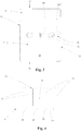
- reference number 1 overall indicates a coupling unit for panels, object of the present invention.
- the present coupling unit 1 is intended to be advantageously employed for fixing panels (such as boards or strips) in particular adapted to form flooring (such as strip-like foundations, parquet for outdoor settings, decking, etc.) or wall facade cladding.
- each panel 2 (which can be made of different materials, such as wood, synthetic, WPC, etc.) is provided with two opposite main faces 3 (of which one is intended to remain visible) and is extended linearly, preferably with elongated shape, between two head edges 4 along a longitudinal axis L.
- each panel 2 is transversely delimited by two lateral sides 5 which are extended along the longitudinal axis L, preferably parallel to each other, to connect the two head edges 4.
- each lateral side 5 of the panel 2 is provided with a longitudinal groove 6 made in the thickness between the two main faces 3 and extended between the two head edges 4 parallel to the longitudinal axis L.
- the longitudinal groove 6 is delimited width-wise by two corresponding shoulders 7, preferably parallel to each other.
- the longitudinal groove 6 can be positioned symmetrically at the same distance from the two main faces 3 of the panel 2 (as in the examples of figures 27a and 27b ) or at different distances from the main faces 3 (as in the examples of figures 27c and 27d ).
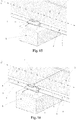
- the panels 2 are intended to be arranged one next to the other, with a lateral side 5 of each panel 2 adjacent to the lateral side 5 of the adjacent panel 2, and possibly also in succession one after the other with the head edge 4 of each panel 2 adjacent to the head edge 4 of the successive panel 2 (as exemplified in figures 6, 7 , 15, 16 , 19, 20 , 23, 24 , 26 , 27a-d ).
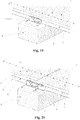
- the coupling unit 1 is advantageously intended to be applied between at least two side-by-side panels 2 in order to act on the corresponding adjacent lateral sides 5 of such panels 2, in intermediate position between the head edges 4 (in a manner such to act on only one panel 2 per side, as in the examples of figures 6 , 11 , 15 , 19 , 23 ) or at one of the head edges 4 (in a manner such to act, on at least one side, on two successive panels 2, as in the examples of figures 7 , 12 , 16 , 20 , 24 , 26 ).
- the present coupling unit 1 is adapted to integrally fix the panel 2 to a support structure 8 (in technical jargon termed nailing/gluing strip) anchored to the ground or to the wall to be clad.
- a support structure 8 in technical jargon termed nailing/gluing strip
- such support structure 8 can comprise a framework with parallel boards, made of different materials such as wood (as in figures 27b and 27d ) or metal (as in figures 27a and 27c ).
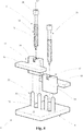
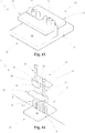
- the present coupling unit 1 comprises a base body 9 intended to be fixed to the support structure 8. More in detail, the base body 9 is provided with two opposite faces 10, 11, preferably flat and parallel to each other, including a bottom face 10 intended to be abutted against the support structure 8 and an opposite front face 11 against which the panel 2 is advantageously intended to be abutted (in particular with a portion of the main face 3 of the latter intended to remain concealed).
- the base body 9 has plate-like shape extended on a lying plane intended to be parallel to that of the panels 2.
- the base body 9 is provided with two opposite sides 12, at each of which the lateral side 5 of the corresponding panel 2 is intended to be arranged.
- the base body 9 is arranged between two side-by-side panels 2, receiving, in abutment against one of its sides 12, the lateral side 5 of a panel 2, and against the other side 12 the lateral side 5 of the adjacent panel 2.
- the coupling unit 1 is arranged at the head of the panel 2 (as in the examples of figures 7 , 12 , 16 , 20 , 24 , 26 )
- the two adjacent head edges 4 of the two successive panels 2 will be abutted against at least one side 12 of the base body 9.
- the base body 9 has substantially quadrangular shape (e.g. rectangular or square) with two lateral edges, parallel to each other, at the two sides 12.
- the base body 9 can have shape different from quadrangular, e.g. circular, with the lateral edges that can even be non-parallel and/or non-rectilinear.
- the bottom face 10 of the base body 9 is substantially flat so as to facilitate an easy abutment against the support structure 8, without the latter requiring particular processing for allowing the installation of the panels 2.
- the base body 9 is extended, in particular on its lying plane, at least according to an alignment direction X intended to be parallel to the longitudinal axis L of the panels 2 and which defines, on both sides, the two sides 12 of the base body 9 itself.
- the coupling unit 1 comprises at least two retention bodies 13 fixed to the base body 9 and adapted to engage, on the opposite sides 12 of the base body 9, the two side-by-side panels 2 between which the coupling unit 1 itself is arranged.
- Each of the aforesaid retention bodies 13 comprises a stem portion 14 which is extended along an extension direction Y' orthogonal to the front face 11 of the base body 9 (and in particular orthogonal to the lying plane of the latter).
- the stem portion 14 is extended, along the aforesaid extension direction Y', between a first end 15, which is directed towards the front face 11 of the base body 9, and an opposite second end 16, preferably free and intended to be directed outward.
- the stem portion 14 is provided with a first face 17 and with a second face 18 which are directed in opposite directions with respect to each other and are extended between the first end 15 and the second end 16 of the stem portion 14 itself.
- the aforesaid first face 17 of the stem portion 14 is intended to be directed, substantially exclusively, towards the lateral side 5 of the corresponding panel 2 on which the retention body 13 acts.
- the first face 17 is substantially exclusively oriented on the corresponding side 12 of the base body 9.
- each retention body 13 is provided, only on its first face 17, with an engagement portion 19, which is projectingly extended from such first face 17 with a length such to be inserted in the longitudinal groove 6 of the lateral side 5 of the corresponding panel 2 in order to be engaged with the latter.
- the engagement portion 19 is extended parallel to the front face 11 of the base body 9 and preferably is extended from the first face 17 of the stem portion 14 orthogonally to the extension direction Y' of the latter (and in particular to its first face 17).
- the engagement portion 19 is placed at the second end 16 of the stem portion 14, in a manner such that the retention body 13 has a transverse profile (obtained with a section on a plane orthogonal to the alignment direction X) of substantially overturned L-shape.
- the two retention bodies 13 of the coupling unit 1 are positioned with their respective engagement portions 19 arranged, with respect to each other, on the opposite sides 12 of the base body 9 so as to be engaged with the adjacent lateral sides 5 of two side-by-side panels 2.
- at least one of the retention bodies 13 has its engagement portion 19 exclusively arranged on one of the sides 12 of the base body 19, and at least another of the retention bodies 13 has its engagement portion 19 exclusively arranged on the other of the sides 12 of the base body 19.
- the second face 18 of the stem portion 14 of the retention body 13 lacks engagement portions, in a manner such to not interfere with the panel 2 adjoining that against which the engagement portion 19 of such retention body 13 acts.
- the coupling unit 1 can also comprise more than two retention bodies 13, as a function for example of the shapes of the engagement portions 19 and of the particular application conditions.
- three retention bodies 13 are provided, of which one is directed with its engagement portion 19 on a side 12 of the base body 9, and the other two are directed with their engagement portions 19 towards the other side 12 in order to be engaged with two successive corresponding panels 2 at the adjacent head edges 4 of the latter.
- the retention bodies 13 are arranged with their step portions 14 aligned one next to the other according to the alignment direction X of the base body 9.
- the stem portion 14 of each retention body 13 is provided with at least one through hole 20 extended from the second end 16 up to the first end 15 of the stem portion 14 itself.
- the stem portion 14 is advantageously provided with multiple through holes 20 (e.g. two) preferably arranged aligned with each other according to the alignment direction X of the base body 9.
- the coupling unit 1 comprises, for each retention body 13, at least one adjustment element 21 (or multiple adjustment elements 21), which is inserted in the corresponding through hole 20, being engaged with the retention body 13, and is configured for rigidly fixing the latter to the base body 9 in an adjustable manner along the aforesaid extension direction Y'.
- the adjustment element 21 acts on the retention body 13, forcing it towards the base body 9, in a manner such that the engagement portion 19 of the retention body 13 acts in abutment against a shoulder 7 of the longitudinal groove 6 in which it is inserted, pressing the panel 2 against the front face 11 of the base body 9.
- the adjustment element 21 is capable of fixing the retention body 13 at different distances from the base body 9, in a manner such that the coupling unit 1 is capable of being adapted to panels 2 with different thickness or with longitudinal grooves 6 arranged at difference distances from the main faces 3 of the panel 2.
- the adjustment element 21 is configured for continuously varying the position of the retention body 13 with respect to the base body 9 along the extension direction Y'.
- each retention body 13 acts, with its engagement portion 19, only on the corresponding side of the coupling unit 1 (i.e. only side 12 of the base body 9 on which the engagement portion 19 is extended) and keeps fixed only the panel/panels 2 present on that side 12.
- the adjustment element 21 is provided with a threaded portion 22 extended, preferably with elongated shape, along an extension axis Y" parallel to the extension direction Y' of the stem portion 14 of the retention body 13.
- Such threaded portion 22 is provided with a thread 23 extended around the extension axis Y" and adapted to be engaged in order to fix the retention body 13 at a specific distance from the base body 9 according to the aforesaid extension direction Y'.
- the threaded portion 22 of the adjustment element 21 is adapted to be engaged via screwing to the support structure 8 and/or to the base body 9, in accordance, in particular, with the embodiment versions described in detail hereinbelow.
- the adjustment element 21 is provided with a head portion 24 which acts in abutment against the retention body 13, in a manner such that, following the engagement via screwing of the threaded portion 22, it is adapted to push against the retention body 13 in order to force the engagement portion 19 of the latter to act on the shoulder 7 of the longitudinal groove 6 of the panel 2 in order to retain it with support structure 8.
- the head portion 24 of the adjustment element 21 is adapted to abut against the second end 16 of the stem portion 14 of the retention body 13, in particular within a seat 25 made in such second end 16.
- the adjustment element 21 is in screw form, the stem being inserted in the corresponding through hole 20 (and engaged via screwing with the base body 9 or with the support structure 8) and the head acting in abutment against the second end 16 of the stem portion 14 of the retention body 13.
- the adjustment element 21 can for example be in the form of a tie rod, grub screw, pin, etc., preferably threaded, and configured for adjustably fixing the retention body 13 to the base body 9, in accordance with that discussed above.
- the adjustment element 21 can also act as element for fixing the base body 9 to the support structure 8 (as in the examples of figures 1-24 ) or separate fixing elements 27 can be provided for constraining the base body 9 to the support structure 8 (as in the examples of figures 25 and 26 ).
- the adjustment element 21 also acts as fixing element for the base body 9
- the latter is provided with one or more passage holes 26, each of which aligned with the corresponding through hole 20 of the retention body 13 in which the adjustment element 21 is inserted. In this manner, such adjustment element 21 passes through the corresponding passage hole 26 in order to be engaged with the support structure 8 so as to fix the latter the base body 9.
- the adjustment element 21 engages via screwing, with its threaded portions 22, the support structure 8, and pushes, in abutment with its head portion 24, the retention body 13 which consequently pushes the panel 2 against the front face 11 of the base body 9, retaining the latter rigidly fixed to the support structure 8.
- Such embodiment in which the adjustment element 21 also determines the fixing of the base body 9, involves a greater installation speed as well as a structural simplification.
- the coupling unit 1 comprises, in addition to the adjustment elements 21, one or more fixing elements 27 separate from the adjustment elements 21 and adapted to rigidly constrain the base body 9 to the support structure 8.
- the base body 9 is provided with one or more fixing holes 28 (separate from the through holes 20) intended to be traversed by the corresponding fixing elements 27.
- each fixing hole 28 is extended in a through manner from the front face 11 to the bottom face 10 of the base body 9 in order to allow the passage of the fixing element 27. More in detail, the latter is inserted in the corresponding fixing hole 28 in order to be engaged with the support structure 8 and acts on the base body 9 in order to rigidly fix such base body 9 to the support structure 8.
- the fixing element 27 comprises an elongated body 29 (preferably threaded) inserted in the corresponding fixing hole 28, penetrating with one end (in particular via screwing) into the support structure 8 and being provided at the other end with a widened portion 30 adapted to abut against the front face 11 of the base body 9.
- the fixing element 27 is obtained by means of a screw (as in the example of figure 25 ), or otherwise with other fixing systems such as a grub screw, a nail, etc.
- Such embodiment which provides for separate fixing elements 27 and adjustment elements 21, involves a greater standardization and versatility in use.
- the base body 9 is fixable to the support structure by means of different fixing means, such as fitting, glue etc.
- the base body 9 is provided with one or more adjustment holes 31, preferably threaded, in each of which the corresponding adjustment element 21 - and, in particular, the threaded portion 22 of the latter - being engaged.
- adjustment holes 31 can be through, or blind (i.e. open only on the back of the front face 11 of the base body 9).
- the coupling unit 1 can be provided with separate fixing elements 27 and it can also be provided that adjustment elements 21 penetrate into the support structure 8 as further constraining element.
- the base body 9 of the coupling unit 1 is provided at least with a guide 32 extended orthogonally to the front face 11 of the base body 9 and with which the retention body 13 is slidably engaged, in a manner such to guide the latter during its application and during the application of the adjustment elements 21, maintaining the engagement portion 19 substantially parallel to the front face 11 of the base body 9 and, hence, to the panel 2.
- the guide 32 of the base body 9 blocks the retention body 13 with respect to rotation movements around the extension direction Y' of the stem portion 14 of the retention body 13 itself, so as in particular to apply the latter to the base body 9, maintaining its engagement portion 19 exclusively directed towards the corresponding side 12 of the base body 9.
- the guide 32 of the base body 9 is extended parallel to the extension direction Y' of the stem portion 14 of the retention body 13 and, in particular, orthogonal to the engagement portion of the latter.
- the guide 32 comprises one or more guide portions 33, each of which projectingly extended from the front face 11 of the base body 9 orthogonal to such front face 11.
- the retention body 13 is provided with corresponding guide seats 34, in each of which the respective guide portion 33 being inserted, in a manner so as to allow the retention body 13 to slide along the guide portion 33 itself.
- the guide portion 33 comprises a pin which is extended according to an axis parallel to the extension direction Y' of the stem portion 14 and orthogonal to the front face 11 of the base body 9.
- the guide seat 34 comprises a guide hole which is extended with axis parallel to the extension direction Y' of the stem portion 14 and in which the corresponding pin of the guide portion 33 is inserted.
- the guide hole is made in the stem portion 14 of the retention body 13 and is extended starting from the first end 15 of the stem portion 14 itself.
- the guide hole can be blind (as in the examples of figures 1-12 and 25-26 ) or through, reaching up to the second end 16 of the stem portion 14 (as in the examples of figures 13-24 ).
- the guide seat 34 is at least partially counter-shaped with respect to the corresponding guide portion 33, in a manner such to be able to allow the slidable coupling, preventing displacements transverse to the extension direction Y'.
- the guide portion 33 (and the corresponding guide seat 34) can have cross section (with respect to their axis) with circular shape (as in the examples of figures 1-24 ) or quadrangular shape (as in the example of figure 25-26 ), or even with another shape (e.g. elliptical) not illustrated in the enclosed figures.
- the adjustment holes 31 are made in the guide portions 33, and in such holes the adjustment elements 21 (in particular in the case of separate fixing elements 27) are engaged.
- each retention body 13 is provided with an abutment surface 35 directed towards the front face 11 of the base body 9 and intended to abut against the shoulder 7 of the longitudinal groove 6 of the corresponding panel 2 in order to push the latter (following the action of the adjustment elements 21) against the base body 9 so as to fix the panel 2 itself.
- the abutment surface 35 of the engagement portion 19 is provided with projecting portions 36 adapted to be engaged in the shoulder 7 of the longitudinal groove 6, at least partially penetrating into such shoulder 7, so as to better anchor the retention body 13 to the panel 2.
- projecting portions 36 comprise a plurality of tips or teeth (as in the illustrated example), or roughness, knurling, spikes, etc.
- the stem portion 14 of the retention body 13 is extended width-wise between a first side 37' and a second side 37", between which the first face 17 and the second face 18 of the stem portion 14 itself are extended.
- the stem portion 14 is extended width-wise parallel to the alignment direction X of the base body 9, preferably with shape elongated according to such alignment direction X.
- the engagement portion 19 is extended width-wise beyond at least one of the aforesaid sides 37', 37", in particular parallel to the alignment direction X.
- the engagement portion 19 is extended projectingly beyond only one of the sides 37', 37" of the stem portion 14, and with reference to the examples of figures 8-12 and 21-24 , the engagement portion 19 is extended projectingly beyond both sides 37', 37" of the stem portion 14.
- each retention body 13 that projects beyond the side 37', 37" of the corresponding stem portion 14 is extended, at least partially, in front of the second face 18 of the retention body 13 oriented on the opposite side 12 of the base body 9.
- the bottom face 10 of the base body 9 is provided with one or more storage cavities 37, each obtained around the corresponding passage hole 26, and preferably positioned coaxial with the latter.
- such storage cavities 37 have the function of collecting, at their interior, the chip that is generated when the threaded portion 22 of the adjustment element 21 is screwed in the support structure 8. This prevents the chip from being accumulated between the support structure 8 and the bottom face 10 of the base body 9, hence preventing such chip accumulations from displacing the base body 9 and misaligning its alignment direction X with respect to the position that the panels 2 must assume.
- the storage cavities 37 can be arranged, as an alternative or additionally, at the fixing holes 28 if present in the base body 9 (for example provided in the example of figures 25 and 26 ).
- the base body 9 is extended along the alignment direction X between a first edge 9' and a second edge 9", preferably substantially parallel to each other and orthogonal to the alignment direction X itself.
- the base body 9 is provided with one or more alignment teeth 38, which are projectingly extended from the first edge 9' of the base body 9, preferably parallel to the alignment direction X and in particular coplanar with the bottom face 10 of the base body 9 itself.
- the base body 9 comprises one or more alignment grooves 39 made on the second edge 9" of the base body 9 (in particular starting from the bottom face 10 of the latter) and intended to receive, at their interior, corresponding alignment teeth 38 of an adjacent base body 9.
- each alignment groove 39 is aligned with the corresponding alignment tooth 38 (placed on the first edge 9') according to the alignment direction X.
- each alignment groove 39 has shape at least partly corresponding with that of the corresponding alignment tooth 38 (e.g. with the same width).
- the alignment teeth 38 and the alignment grooves 39 are configured in a manner such that multiple base bodies 9 can be arranged one after the other (along their alignment direction X) by inserting the alignment teeth 38 of a base body 9 in the alignment grooves 39 of the successive base body 9, such that the two base bodies 9 are correctly aligned with each other and are not subjected to mutual displacements (transverse to the alignment direction X) during the steps of application of the coupling unit 1, for example during the application of the adjustment elements 21.
- the base body 9 is provided with at least one weakening line 40 which is made on the front face 11 and/or on the bottom face 10 of the base body 9 itself, is extended parallel to the alignment direction X of the base body 9, and is positioned on one side of the passage holes 26 (and advantageously of the guide portions 33) with respect to the alignment direction X.
- the weakening line 40 (obtained for example with an elongated groove) defines a first portion 41 in the base body 9, which contains the passage holes 26 (and advantageously the guide portions 33), and a remaining second portion 42, arranged on the side opposite the first portion 41 with respect to the weakening line 40.
- such weakening line 40 allows breaking the base body 9 into the aforesaid portions 41, 42, allowing the use of the first portion 41 at the terminal panels 2 which delimit the lateral edge of the floor or of the cladding, receiving in abutment such terminal panels 2 in a manner such that such first portion 41 projects from the opposite side of the panel 2 only for a brief section where the passage holes 26 are made.
- one or more retention bodies 13 are made which are directed with their engagement portion 19 only towards the corresponding terminal panel 2.
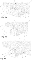
- the base bodies 9 can be arranged with different lengths according to the alignment direction X, as exemplified for example in the two embodiment variants illustrated in figures 28a-b and 29a-b . This allows configuring the base bodies 9 separately or in series as a function of the different application situations, as illustrated by way of example in the examples of figures 30a-c .
- the abovementioned characteristics of the aforesaid seventh embodiment can be arranged independently without one or more of the others and, in particular, they can be arranged, separately or together, in the other embodiments of the present invention which were described above.
- the base body 9 and the retention body 13 of the coupling unit 1 are made of substantially rigid material, e.g. metallic material or rigid synthetic materials.
- the invention thus conceived therefore attains the pre-established object.
- the present coupling unit 1 allows being able to easily substitute a single panel 2 (or two adjacent panels), independently from the surrounding panels 2 of the floor or of the cladding, since each retention body 13 is fixed to the base body 9 in an independent manner with respect to the other retention bodies 13 and is configured for keeping fixed the panel or panels 2 arranged only on the corresponding side 12 of the base body 9.
- the adjustment elements 21 according to the invention allow obtaining such advantage without requiring complex processing of the lateral sides 5 of the panels 2 or of the support structure 8, with a consequent improved efficiency and versatility of use, in particular continuing to allow viewing one of the main faces 3 of the panel 2 or the other, allowing the application of different surface finishes for different uses on such main faces 3.
- the possibility of adjustment given by the adjustment elements 21 of the coupling unit 1 renders it suitable for any thickness of panel 2.
- the substantially flat arrangement of the bottom face 10 of the base body allows the installation thereof without requiring the use of specific shapes of the support structure 8, nor requiring particular processing (e.g. milling or channeling) on the latter.
Landscapes
- Engineering & Computer Science (AREA)
- Architecture (AREA)
- Civil Engineering (AREA)
- Structural Engineering (AREA)
- Connection Of Plates (AREA)
- Finishing Walls (AREA)
- Floor Finish (AREA)
- Inverter Devices (AREA)
- Main Body Construction Of Washing Machines And Laundry Dryers (AREA)
- Polysaccharides And Polysaccharide Derivatives (AREA)
- Unwinding Webs (AREA)
- Pharmaceuticals Containing Other Organic And Inorganic Compounds (AREA)
- Joining Of Building Structures In Genera (AREA)
Priority Applications (1)
| Application Number | Priority Date | Filing Date | Title |
|---|---|---|---|
| SI201930195T SI3660241T1 (sl) | 2018-11-29 | 2019-11-29 | Sklopna enota za panele |
Applications Claiming Priority (1)
| Application Number | Priority Date | Filing Date | Title |
|---|---|---|---|
| IT102018000010700A IT201800010700A1 (it) | 2018-11-29 | 2018-11-29 | Gruppo di aggancio per pannelli |
Publications (2)
| Publication Number | Publication Date |
|---|---|
| EP3660241A1 true EP3660241A1 (de) | 2020-06-03 |
| EP3660241B1 EP3660241B1 (de) | 2022-01-05 |
Family
ID=65576529
Family Applications (1)
| Application Number | Title | Priority Date | Filing Date |
|---|---|---|---|
| EP19212439.4A Active EP3660241B1 (de) | 2018-11-29 | 2019-11-29 | Kopplungseinheit für paneele |
Country Status (7)
| Country | Link |
|---|---|
| EP (1) | EP3660241B1 (de) |
| KR (1) | KR102733159B1 (de) |
| ES (1) | ES2910264T3 (de) |
| IL (1) | IL271029B2 (de) |
| IT (1) | IT201800010700A1 (de) |
| PT (1) | PT3660241T (de) |
| SI (1) | SI3660241T1 (de) |
Cited By (4)
| Publication number | Priority date | Publication date | Assignee | Title |
|---|---|---|---|---|
| EP4056783A1 (de) * | 2021-03-12 | 2022-09-14 | Forestia | Vorrichtung zur befestigung von terrassendielen an eine unterlage |
| EP4361374A1 (de) * | 2022-10-28 | 2024-05-01 | Günther Gaisbauer | Terrassensystem und halteteil zum verbinden eines ersten und eines zweiten terrassenprofils mit einer unterkonstruktion des terrassensystems |
| EP4361373A1 (de) * | 2022-10-28 | 2024-05-01 | Günther Gaisbauer | Terrassensystem und halteteil hierfür |
| WO2024173959A1 (de) * | 2023-02-24 | 2024-08-29 | Gaisbauer Guenther | Terrassensystem und halteteil zum verbinden eines ersten und eines zweiten terrassenprofils mit einer unterkonstruktion des terrassensystems |
Families Citing this family (1)
| Publication number | Priority date | Publication date | Assignee | Title |
|---|---|---|---|---|
| USD1121421S1 (en) | 2023-08-17 | 2026-04-07 | Trex Company, Inc. | Fastener clip |
Citations (7)
| Publication number | Priority date | Publication date | Assignee | Title |
|---|---|---|---|---|
| US20090019805A1 (en) | 2007-07-18 | 2009-01-22 | Marcello Zanelli | Nail-Free Decking System |
| EP2267241A1 (de) | 2009-06-25 | 2010-12-29 | Giovanni Iovene | System zum Verlegen von Holzböden im Aussen- und Innenbereich, geeignet für stringenten Kontrolle |
| EP2995744A2 (de) * | 2014-09-09 | 2016-03-16 | Stefan Ehrenreich | Vorrichtung zur befestigung von dielen auf einer unterkonstruktion |
| EP3106585A1 (de) * | 2015-06-15 | 2016-12-21 | Elmich Pte Ltd | Befestigungssystem für terrassenplatten |
| US20170058534A1 (en) | 2015-08-24 | 2017-03-02 | Välinge Innovation AB | Panel with a fastening device |
| US20180223547A1 (en) * | 2017-02-06 | 2018-08-09 | MN Fastener LLC | Hidden clip and fastening system for decking |
| US20180238060A1 (en) * | 2017-02-21 | 2018-08-23 | Klevaklip Systems Pty Ltd. | Decking clip |
-
2018
- 2018-11-29 IT IT102018000010700A patent/IT201800010700A1/it unknown
-
2019
- 2019-11-28 IL IL271029A patent/IL271029B2/en unknown
- 2019-11-29 EP EP19212439.4A patent/EP3660241B1/de active Active
- 2019-11-29 SI SI201930195T patent/SI3660241T1/sl unknown
- 2019-11-29 KR KR1020190156620A patent/KR102733159B1/ko active Active
- 2019-11-29 ES ES19212439T patent/ES2910264T3/es active Active
- 2019-11-29 PT PT192124394T patent/PT3660241T/pt unknown
Patent Citations (7)
| Publication number | Priority date | Publication date | Assignee | Title |
|---|---|---|---|---|
| US20090019805A1 (en) | 2007-07-18 | 2009-01-22 | Marcello Zanelli | Nail-Free Decking System |
| EP2267241A1 (de) | 2009-06-25 | 2010-12-29 | Giovanni Iovene | System zum Verlegen von Holzböden im Aussen- und Innenbereich, geeignet für stringenten Kontrolle |
| EP2995744A2 (de) * | 2014-09-09 | 2016-03-16 | Stefan Ehrenreich | Vorrichtung zur befestigung von dielen auf einer unterkonstruktion |
| EP3106585A1 (de) * | 2015-06-15 | 2016-12-21 | Elmich Pte Ltd | Befestigungssystem für terrassenplatten |
| US20170058534A1 (en) | 2015-08-24 | 2017-03-02 | Välinge Innovation AB | Panel with a fastening device |
| US20180223547A1 (en) * | 2017-02-06 | 2018-08-09 | MN Fastener LLC | Hidden clip and fastening system for decking |
| US20180238060A1 (en) * | 2017-02-21 | 2018-08-23 | Klevaklip Systems Pty Ltd. | Decking clip |
Cited By (5)
| Publication number | Priority date | Publication date | Assignee | Title |
|---|---|---|---|---|
| EP4056783A1 (de) * | 2021-03-12 | 2022-09-14 | Forestia | Vorrichtung zur befestigung von terrassendielen an eine unterlage |
| FR3120642A1 (fr) * | 2021-03-12 | 2022-09-16 | Forestia | Dispositif de fixation de lames de terrasse à un support |
| EP4361374A1 (de) * | 2022-10-28 | 2024-05-01 | Günther Gaisbauer | Terrassensystem und halteteil zum verbinden eines ersten und eines zweiten terrassenprofils mit einer unterkonstruktion des terrassensystems |
| EP4361373A1 (de) * | 2022-10-28 | 2024-05-01 | Günther Gaisbauer | Terrassensystem und halteteil hierfür |
| WO2024173959A1 (de) * | 2023-02-24 | 2024-08-29 | Gaisbauer Guenther | Terrassensystem und halteteil zum verbinden eines ersten und eines zweiten terrassenprofils mit einer unterkonstruktion des terrassensystems |
Also Published As
| Publication number | Publication date |
|---|---|
| IL271029B2 (en) | 2023-11-01 |
| KR20200066234A (ko) | 2020-06-09 |
| IL271029B1 (en) | 2023-07-01 |
| IL271029A (en) | 2020-05-31 |
| PT3660241T (pt) | 2022-03-24 |
| SI3660241T1 (sl) | 2022-05-31 |
| IT201800010700A1 (it) | 2020-05-29 |
| ES2910264T3 (es) | 2022-05-12 |
| KR102733159B1 (ko) | 2024-11-21 |
| EP3660241B1 (de) | 2022-01-05 |
Similar Documents
| Publication | Publication Date | Title |
|---|---|---|
| EP3660241B1 (de) | Kopplungseinheit für paneele | |
| US8925271B1 (en) | System for mounting wall panels to a wall structure | |
| EP3555387B1 (de) | Satz aus terrassenplatten mit einem verbindungssystem | |
| US8627862B2 (en) | Mechanical locking of floor panels, methods to install and uninstall panels, a method and an equipment to produce the locking system, a method to connect a displaceable tongue to a panel and a tongue blank | |
| US10954989B2 (en) | Screw with irregular knurling pattern | |
| US20240229472A1 (en) | Exterior cladding panels and methods for installing them | |
| CA3047012A1 (en) | Panels, mounting clamps and wall or ceiling covering for a 3-dimensional pattern of wall- and ceiling panels | |
| US20260009234A1 (en) | Wall or ceiling panels and wall or ceiling covering | |
| WO2013156985A1 (en) | Ceiling plank | |
| NZ759637A (en) | Coupling Unit for Panels | |
| US5042220A (en) | Fastener and strip mounting system | |
| EP0719953B1 (de) | Vorrichtung zum Höhenausgleich von Bauelementen | |
| CN103362264B (zh) | 饰面装置 | |
| DE4115900A1 (de) | Befestigungssystem fuer decken- oder wandverkleidungen | |
| DE202016100284U1 (de) | System für die Innendämmung von Gebäuden, insbesondere von Schrägdächern | |
| DE202011110218U1 (de) | Verbindung von Modulen | |
| EP2392749A2 (de) | Halteprofil und Set mit Halteprofil | |
| DE4320190A1 (de) | Gebäudewandverkleidung | |
| US2117198A (en) | Flooring | |
| DE2621160A1 (de) | Einrichtung zum befestigen von profilbrettern fuer decken- und wandverkleidungen | |
| JP6808196B2 (ja) | 連結構造 | |
| DE29823195U1 (de) | Verbund von Brettern | |
| US2676365A (en) | Edgewise splicer for boardlike members | |
| US977796A (en) | Parquet flooring. | |
| DE19835204B4 (de) | Befestigungsband und Holzbalkenkonstruktion mit Befestigungsband |
Legal Events
| Date | Code | Title | Description |
|---|---|---|---|
| PUAI | Public reference made under article 153(3) epc to a published international application that has entered the european phase |
Free format text: ORIGINAL CODE: 0009012 |
|
| STAA | Information on the status of an ep patent application or granted ep patent |
Free format text: STATUS: THE APPLICATION HAS BEEN PUBLISHED |
|
| AK | Designated contracting states |
Kind code of ref document: A1 Designated state(s): AL AT BE BG CH CY CZ DE DK EE ES FI FR GB GR HR HU IE IS IT LI LT LU LV MC MK MT NL NO PL PT RO RS SE SI SK SM TR |
|
| AX | Request for extension of the european patent |
Extension state: BA ME |
|
| STAA | Information on the status of an ep patent application or granted ep patent |
Free format text: STATUS: REQUEST FOR EXAMINATION WAS MADE |
|
| 17P | Request for examination filed |
Effective date: 20201203 |
|
| RBV | Designated contracting states (corrected) |
Designated state(s): AL AT BE BG CH CY CZ DE DK EE ES FI FR GB GR HR HU IE IS IT LI LT LU LV MC MK MT NL NO PL PT RO RS SE SI SK SM TR |
|
| GRAP | Despatch of communication of intention to grant a patent |
Free format text: ORIGINAL CODE: EPIDOSNIGR1 |
|
| STAA | Information on the status of an ep patent application or granted ep patent |
Free format text: STATUS: GRANT OF PATENT IS INTENDED |
|
| INTG | Intention to grant announced |
Effective date: 20210706 |
|
| GRAS | Grant fee paid |
Free format text: ORIGINAL CODE: EPIDOSNIGR3 |
|
| GRAA | (expected) grant |
Free format text: ORIGINAL CODE: 0009210 |
|
| STAA | Information on the status of an ep patent application or granted ep patent |
Free format text: STATUS: THE PATENT HAS BEEN GRANTED |
|
| AK | Designated contracting states |
Kind code of ref document: B1 Designated state(s): AL AT BE BG CH CY CZ DE DK EE ES FI FR GB GR HR HU IE IS IT LI LT LU LV MC MK MT NL NO PL PT RO RS SE SI SK SM TR |
|
| REG | Reference to a national code |
Ref country code: GB Ref legal event code: FG4D |
|
| REG | Reference to a national code |
Ref country code: CH Ref legal event code: EP |
|
| REG | Reference to a national code |
Ref country code: AT Ref legal event code: REF Ref document number: 1460741 Country of ref document: AT Kind code of ref document: T Effective date: 20220115 |
|
| REG | Reference to a national code |
Ref country code: DE Ref legal event code: R096 Ref document number: 602019010657 Country of ref document: DE |
|
| REG | Reference to a national code |
Ref country code: IE Ref legal event code: FG4D |
|
| REG | Reference to a national code |
Ref country code: PT Ref legal event code: SC4A Ref document number: 3660241 Country of ref document: PT Date of ref document: 20220324 Kind code of ref document: T Free format text: AVAILABILITY OF NATIONAL TRANSLATION Effective date: 20220317 |
|
| REG | Reference to a national code |
Ref country code: LT Ref legal event code: MG9D |
|
| REG | Reference to a national code |
Ref country code: NL Ref legal event code: MP Effective date: 20220105 |
|
| REG | Reference to a national code |
Ref country code: ES Ref legal event code: FG2A Ref document number: 2910264 Country of ref document: ES Kind code of ref document: T3 Effective date: 20220512 |
|
| REG | Reference to a national code |
Ref country code: AT Ref legal event code: MK05 Ref document number: 1460741 Country of ref document: AT Kind code of ref document: T Effective date: 20220105 |
|
| PG25 | Lapsed in a contracting state [announced via postgrant information from national office to epo] |
Ref country code: NL Free format text: LAPSE BECAUSE OF FAILURE TO SUBMIT A TRANSLATION OF THE DESCRIPTION OR TO PAY THE FEE WITHIN THE PRESCRIBED TIME-LIMIT Effective date: 20220105 |
|
| PG25 | Lapsed in a contracting state [announced via postgrant information from national office to epo] |
Ref country code: SE Free format text: LAPSE BECAUSE OF FAILURE TO SUBMIT A TRANSLATION OF THE DESCRIPTION OR TO PAY THE FEE WITHIN THE PRESCRIBED TIME-LIMIT Effective date: 20220105 Ref country code: RS Free format text: LAPSE BECAUSE OF FAILURE TO SUBMIT A TRANSLATION OF THE DESCRIPTION OR TO PAY THE FEE WITHIN THE PRESCRIBED TIME-LIMIT Effective date: 20220105 Ref country code: NO Free format text: LAPSE BECAUSE OF FAILURE TO SUBMIT A TRANSLATION OF THE DESCRIPTION OR TO PAY THE FEE WITHIN THE PRESCRIBED TIME-LIMIT Effective date: 20220405 Ref country code: LT Free format text: LAPSE BECAUSE OF FAILURE TO SUBMIT A TRANSLATION OF THE DESCRIPTION OR TO PAY THE FEE WITHIN THE PRESCRIBED TIME-LIMIT Effective date: 20220105 Ref country code: HR Free format text: LAPSE BECAUSE OF FAILURE TO SUBMIT A TRANSLATION OF THE DESCRIPTION OR TO PAY THE FEE WITHIN THE PRESCRIBED TIME-LIMIT Effective date: 20220105 Ref country code: BG Free format text: LAPSE BECAUSE OF FAILURE TO SUBMIT A TRANSLATION OF THE DESCRIPTION OR TO PAY THE FEE WITHIN THE PRESCRIBED TIME-LIMIT Effective date: 20220405 |
|
| PG25 | Lapsed in a contracting state [announced via postgrant information from national office to epo] |
Ref country code: PL Free format text: LAPSE BECAUSE OF FAILURE TO SUBMIT A TRANSLATION OF THE DESCRIPTION OR TO PAY THE FEE WITHIN THE PRESCRIBED TIME-LIMIT Effective date: 20220105 Ref country code: LV Free format text: LAPSE BECAUSE OF FAILURE TO SUBMIT A TRANSLATION OF THE DESCRIPTION OR TO PAY THE FEE WITHIN THE PRESCRIBED TIME-LIMIT Effective date: 20220105 Ref country code: GR Free format text: LAPSE BECAUSE OF FAILURE TO SUBMIT A TRANSLATION OF THE DESCRIPTION OR TO PAY THE FEE WITHIN THE PRESCRIBED TIME-LIMIT Effective date: 20220406 Ref country code: FI Free format text: LAPSE BECAUSE OF FAILURE TO SUBMIT A TRANSLATION OF THE DESCRIPTION OR TO PAY THE FEE WITHIN THE PRESCRIBED TIME-LIMIT Effective date: 20220105 Ref country code: AT Free format text: LAPSE BECAUSE OF FAILURE TO SUBMIT A TRANSLATION OF THE DESCRIPTION OR TO PAY THE FEE WITHIN THE PRESCRIBED TIME-LIMIT Effective date: 20220105 |
|
| PG25 | Lapsed in a contracting state [announced via postgrant information from national office to epo] |
Ref country code: IS Free format text: LAPSE BECAUSE OF FAILURE TO SUBMIT A TRANSLATION OF THE DESCRIPTION OR TO PAY THE FEE WITHIN THE PRESCRIBED TIME-LIMIT Effective date: 20220505 |
|
| REG | Reference to a national code |
Ref country code: DE Ref legal event code: R097 Ref document number: 602019010657 Country of ref document: DE |
|
| PG25 | Lapsed in a contracting state [announced via postgrant information from national office to epo] |
Ref country code: SM Free format text: LAPSE BECAUSE OF FAILURE TO SUBMIT A TRANSLATION OF THE DESCRIPTION OR TO PAY THE FEE WITHIN THE PRESCRIBED TIME-LIMIT Effective date: 20220105 Ref country code: SK Free format text: LAPSE BECAUSE OF FAILURE TO SUBMIT A TRANSLATION OF THE DESCRIPTION OR TO PAY THE FEE WITHIN THE PRESCRIBED TIME-LIMIT Effective date: 20220105 Ref country code: RO Free format text: LAPSE BECAUSE OF FAILURE TO SUBMIT A TRANSLATION OF THE DESCRIPTION OR TO PAY THE FEE WITHIN THE PRESCRIBED TIME-LIMIT Effective date: 20220105 Ref country code: EE Free format text: LAPSE BECAUSE OF FAILURE TO SUBMIT A TRANSLATION OF THE DESCRIPTION OR TO PAY THE FEE WITHIN THE PRESCRIBED TIME-LIMIT Effective date: 20220105 Ref country code: DK Free format text: LAPSE BECAUSE OF FAILURE TO SUBMIT A TRANSLATION OF THE DESCRIPTION OR TO PAY THE FEE WITHIN THE PRESCRIBED TIME-LIMIT Effective date: 20220105 Ref country code: CZ Free format text: LAPSE BECAUSE OF FAILURE TO SUBMIT A TRANSLATION OF THE DESCRIPTION OR TO PAY THE FEE WITHIN THE PRESCRIBED TIME-LIMIT Effective date: 20220105 |
|
| PLBE | No opposition filed within time limit |
Free format text: ORIGINAL CODE: 0009261 |
|
| STAA | Information on the status of an ep patent application or granted ep patent |
Free format text: STATUS: NO OPPOSITION FILED WITHIN TIME LIMIT |
|
| PG25 | Lapsed in a contracting state [announced via postgrant information from national office to epo] |
Ref country code: AL Free format text: LAPSE BECAUSE OF FAILURE TO SUBMIT A TRANSLATION OF THE DESCRIPTION OR TO PAY THE FEE WITHIN THE PRESCRIBED TIME-LIMIT Effective date: 20220105 |
|
| 26N | No opposition filed |
Effective date: 20221006 |
|
| P01 | Opt-out of the competence of the unified patent court (upc) registered |
Effective date: 20230301 |
|
| PG25 | Lapsed in a contracting state [announced via postgrant information from national office to epo] |
Ref country code: IE Free format text: LAPSE BECAUSE OF NON-PAYMENT OF DUE FEES Effective date: 20221129 |
|
| PG25 | Lapsed in a contracting state [announced via postgrant information from national office to epo] |
Ref country code: HU Free format text: LAPSE BECAUSE OF FAILURE TO SUBMIT A TRANSLATION OF THE DESCRIPTION OR TO PAY THE FEE WITHIN THE PRESCRIBED TIME-LIMIT; INVALID AB INITIO Effective date: 20191129 |
|
| PG25 | Lapsed in a contracting state [announced via postgrant information from national office to epo] |
Ref country code: CY Free format text: LAPSE BECAUSE OF FAILURE TO SUBMIT A TRANSLATION OF THE DESCRIPTION OR TO PAY THE FEE WITHIN THE PRESCRIBED TIME-LIMIT Effective date: 20220105 |
|
| PG25 | Lapsed in a contracting state [announced via postgrant information from national office to epo] |
Ref country code: MK Free format text: LAPSE BECAUSE OF FAILURE TO SUBMIT A TRANSLATION OF THE DESCRIPTION OR TO PAY THE FEE WITHIN THE PRESCRIBED TIME-LIMIT Effective date: 20220105 |
|
| PG25 | Lapsed in a contracting state [announced via postgrant information from national office to epo] |
Ref country code: TR Free format text: LAPSE BECAUSE OF FAILURE TO SUBMIT A TRANSLATION OF THE DESCRIPTION OR TO PAY THE FEE WITHIN THE PRESCRIBED TIME-LIMIT Effective date: 20220105 |
|
| PG25 | Lapsed in a contracting state [announced via postgrant information from national office to epo] |
Ref country code: MT Free format text: LAPSE BECAUSE OF FAILURE TO SUBMIT A TRANSLATION OF THE DESCRIPTION OR TO PAY THE FEE WITHIN THE PRESCRIBED TIME-LIMIT Effective date: 20220105 |
|
| REG | Reference to a national code |
Ref country code: CH Ref legal event code: U11 Free format text: ST27 STATUS EVENT CODE: U-0-0-U10-U11 (AS PROVIDED BY THE NATIONAL OFFICE) Effective date: 20251201 |
|
| PGFP | Annual fee paid to national office [announced via postgrant information from national office to epo] |
Ref country code: PT Payment date: 20251120 Year of fee payment: 7 |
|
| PGFP | Annual fee paid to national office [announced via postgrant information from national office to epo] |
Ref country code: LU Payment date: 20251119 Year of fee payment: 7 |
|
| PGFP | Annual fee paid to national office [announced via postgrant information from national office to epo] |
Ref country code: DE Payment date: 20251119 Year of fee payment: 7 |
|
| PGFP | Annual fee paid to national office [announced via postgrant information from national office to epo] |
Ref country code: GB Payment date: 20251121 Year of fee payment: 7 |
|
| PGFP | Annual fee paid to national office [announced via postgrant information from national office to epo] |
Ref country code: MC Payment date: 20251121 Year of fee payment: 7 |
|
| PGFP | Annual fee paid to national office [announced via postgrant information from national office to epo] |
Ref country code: IT Payment date: 20251126 Year of fee payment: 7 |
|
| PGFP | Annual fee paid to national office [announced via postgrant information from national office to epo] |
Ref country code: FR Payment date: 20251126 Year of fee payment: 7 |
|
| PGFP | Annual fee paid to national office [announced via postgrant information from national office to epo] |
Ref country code: BE Payment date: 20251119 Year of fee payment: 7 |
|
| PGFP | Annual fee paid to national office [announced via postgrant information from national office to epo] |
Ref country code: CH Payment date: 20251201 Year of fee payment: 7 |
|
| PGFP | Annual fee paid to national office [announced via postgrant information from national office to epo] |
Ref country code: SI Payment date: 20251120 Year of fee payment: 7 Ref country code: ES Payment date: 20251229 Year of fee payment: 7 |