EP3660946A1 - Bloc-batterie et son procédé de fabrication - Google Patents
Bloc-batterie et son procédé de fabrication Download PDFInfo
- Publication number
- EP3660946A1 EP3660946A1 EP18838494.5A EP18838494A EP3660946A1 EP 3660946 A1 EP3660946 A1 EP 3660946A1 EP 18838494 A EP18838494 A EP 18838494A EP 3660946 A1 EP3660946 A1 EP 3660946A1
- Authority
- EP
- European Patent Office
- Prior art keywords
- connector
- lead wire
- floating connector
- exterior case
- battery pack
- Prior art date
- Legal status (The legal status is an assumption and is not a legal conclusion. Google has not performed a legal analysis and makes no representation as to the accuracy of the status listed.)
- Granted
Links
Images





Classifications
-
- H—ELECTRICITY
- H01—ELECTRIC ELEMENTS
- H01M—PROCESSES OR MEANS, e.g. BATTERIES, FOR THE DIRECT CONVERSION OF CHEMICAL ENERGY INTO ELECTRICAL ENERGY
- H01M50/00—Constructional details or processes of manufacture of the non-active parts of electrochemical cells other than fuel cells, e.g. hybrid cells
- H01M50/50—Current conducting connections for cells or batteries
- H01M50/528—Fixed electrical connections, i.e. not intended for disconnection
-
- H—ELECTRICITY
- H01—ELECTRIC ELEMENTS
- H01M—PROCESSES OR MEANS, e.g. BATTERIES, FOR THE DIRECT CONVERSION OF CHEMICAL ENERGY INTO ELECTRICAL ENERGY
- H01M10/00—Secondary cells; Manufacture thereof
- H01M10/42—Methods or arrangements for servicing or maintenance of secondary cells or secondary half-cells
- H01M10/425—Structural combination with electronic components, e.g. electronic circuits integrated to the outside of the casing
-
- H—ELECTRICITY
- H01—ELECTRIC ELEMENTS
- H01M—PROCESSES OR MEANS, e.g. BATTERIES, FOR THE DIRECT CONVERSION OF CHEMICAL ENERGY INTO ELECTRICAL ENERGY
- H01M10/00—Secondary cells; Manufacture thereof
- H01M10/04—Construction or manufacture in general
-
- H—ELECTRICITY
- H01—ELECTRIC ELEMENTS
- H01M—PROCESSES OR MEANS, e.g. BATTERIES, FOR THE DIRECT CONVERSION OF CHEMICAL ENERGY INTO ELECTRICAL ENERGY
- H01M10/00—Secondary cells; Manufacture thereof
- H01M10/42—Methods or arrangements for servicing or maintenance of secondary cells or secondary half-cells
- H01M10/425—Structural combination with electronic components, e.g. electronic circuits integrated to the outside of the casing
- H01M10/4257—Smart batteries, e.g. electronic circuits inside the housing of the cells or batteries
-
- H—ELECTRICITY
- H01—ELECTRIC ELEMENTS
- H01R—ELECTRICALLY-CONDUCTIVE CONNECTIONS; STRUCTURAL ASSOCIATIONS OF A PLURALITY OF MUTUALLY-INSULATED ELECTRICAL CONNECTING ELEMENTS; COUPLING DEVICES; CURRENT COLLECTORS
- H01R12/00—Structural associations of a plurality of mutually-insulated electrical connecting elements, specially adapted for printed circuits, e.g. printed circuit boards [PCB], flat or ribbon cables, or like generally planar structures, e.g. terminal strips, terminal blocks; Coupling devices specially adapted for printed circuits, flat or ribbon cables, or like generally planar structures; Terminals specially adapted for contact with, or insertion into, printed circuits, flat or ribbon cables, or like generally planar structures
- H01R12/70—Coupling devices
- H01R12/91—Coupling devices allowing relative movement between coupling parts, e.g. floating or self aligning
-
- H—ELECTRICITY
- H01—ELECTRIC ELEMENTS
- H01R—ELECTRICALLY-CONDUCTIVE CONNECTIONS; STRUCTURAL ASSOCIATIONS OF A PLURALITY OF MUTUALLY-INSULATED ELECTRICAL CONNECTING ELEMENTS; COUPLING DEVICES; CURRENT COLLECTORS
- H01R13/00—Details of coupling devices of the kinds covered by groups H01R12/70 or H01R24/00 - H01R33/00
- H01R13/46—Bases; Cases
- H01R13/516—Means for holding or embracing insulating body, e.g. casing, hoods
-
- H—ELECTRICITY
- H01—ELECTRIC ELEMENTS
- H01R—ELECTRICALLY-CONDUCTIVE CONNECTIONS; STRUCTURAL ASSOCIATIONS OF A PLURALITY OF MUTUALLY-INSULATED ELECTRICAL CONNECTING ELEMENTS; COUPLING DEVICES; CURRENT COLLECTORS
- H01R43/00—Apparatus or processes specially adapted for manufacturing, assembling, maintaining, or repairing of line connectors or current collectors or for joining electric conductors
- H01R43/20—Apparatus or processes specially adapted for manufacturing, assembling, maintaining, or repairing of line connectors or current collectors or for joining electric conductors for assembling or disassembling contact members with insulating base, case or sleeve
- H01R43/205—Apparatus or processes specially adapted for manufacturing, assembling, maintaining, or repairing of line connectors or current collectors or for joining electric conductors for assembling or disassembling contact members with insulating base, case or sleeve with a panel or printed circuit board
-
- H—ELECTRICITY
- H01—ELECTRIC ELEMENTS
- H01M—PROCESSES OR MEANS, e.g. BATTERIES, FOR THE DIRECT CONVERSION OF CHEMICAL ENERGY INTO ELECTRICAL ENERGY
- H01M10/00—Secondary cells; Manufacture thereof
- H01M10/42—Methods or arrangements for servicing or maintenance of secondary cells or secondary half-cells
- H01M10/425—Structural combination with electronic components, e.g. electronic circuits integrated to the outside of the casing
- H01M2010/4271—Battery management systems including electronic circuits, e.g. control of current or voltage to keep battery in healthy state, cell balancing
-
- H—ELECTRICITY
- H01—ELECTRIC ELEMENTS
- H01M—PROCESSES OR MEANS, e.g. BATTERIES, FOR THE DIRECT CONVERSION OF CHEMICAL ENERGY INTO ELECTRICAL ENERGY
- H01M50/00—Constructional details or processes of manufacture of the non-active parts of electrochemical cells other than fuel cells, e.g. hybrid cells
- H01M50/10—Primary casings; Jackets or wrappings
- H01M50/172—Arrangements of electric connectors penetrating the casing
- H01M50/174—Arrangements of electric connectors penetrating the casing adapted for the shape of the cells
- H01M50/176—Arrangements of electric connectors penetrating the casing adapted for the shape of the cells for prismatic or rectangular cells
-
- H—ELECTRICITY
- H01—ELECTRIC ELEMENTS
- H01M—PROCESSES OR MEANS, e.g. BATTERIES, FOR THE DIRECT CONVERSION OF CHEMICAL ENERGY INTO ELECTRICAL ENERGY
- H01M50/00—Constructional details or processes of manufacture of the non-active parts of electrochemical cells other than fuel cells, e.g. hybrid cells
- H01M50/20—Mountings; Secondary casings or frames; Racks, modules or packs; Suspension devices; Shock absorbers; Transport or carrying devices; Holders
- H01M50/204—Racks, modules or packs for multiple batteries or multiple cells
- H01M50/207—Racks, modules or packs for multiple batteries or multiple cells characterised by their shape
- H01M50/209—Racks, modules or packs for multiple batteries or multiple cells characterised by their shape adapted for prismatic or rectangular cells
-
- H—ELECTRICITY
- H01—ELECTRIC ELEMENTS
- H01M—PROCESSES OR MEANS, e.g. BATTERIES, FOR THE DIRECT CONVERSION OF CHEMICAL ENERGY INTO ELECTRICAL ENERGY
- H01M50/00—Constructional details or processes of manufacture of the non-active parts of electrochemical cells other than fuel cells, e.g. hybrid cells
- H01M50/20—Mountings; Secondary casings or frames; Racks, modules or packs; Suspension devices; Shock absorbers; Transport or carrying devices; Holders
- H01M50/271—Lids or covers for the racks or secondary casings
-
- Y—GENERAL TAGGING OF NEW TECHNOLOGICAL DEVELOPMENTS; GENERAL TAGGING OF CROSS-SECTIONAL TECHNOLOGIES SPANNING OVER SEVERAL SECTIONS OF THE IPC; TECHNICAL SUBJECTS COVERED BY FORMER USPC CROSS-REFERENCE ART COLLECTIONS [XRACs] AND DIGESTS
- Y02—TECHNOLOGIES OR APPLICATIONS FOR MITIGATION OR ADAPTATION AGAINST CLIMATE CHANGE
- Y02E—REDUCTION OF GREENHOUSE GAS [GHG] EMISSIONS, RELATED TO ENERGY GENERATION, TRANSMISSION OR DISTRIBUTION
- Y02E60/00—Enabling technologies; Technologies with a potential or indirect contribution to GHG emissions mitigation
- Y02E60/10—Energy storage using batteries
-
- Y—GENERAL TAGGING OF NEW TECHNOLOGICAL DEVELOPMENTS; GENERAL TAGGING OF CROSS-SECTIONAL TECHNOLOGIES SPANNING OVER SEVERAL SECTIONS OF THE IPC; TECHNICAL SUBJECTS COVERED BY FORMER USPC CROSS-REFERENCE ART COLLECTIONS [XRACs] AND DIGESTS
- Y02—TECHNOLOGIES OR APPLICATIONS FOR MITIGATION OR ADAPTATION AGAINST CLIMATE CHANGE
- Y02P—CLIMATE CHANGE MITIGATION TECHNOLOGIES IN THE PRODUCTION OR PROCESSING OF GOODS
- Y02P70/00—Climate change mitigation technologies in the production process for final industrial or consumer products
- Y02P70/50—Manufacturing or production processes characterised by the final manufactured product
Definitions
- the present invention relates to a battery pack and a production method for the battery pack.
- Battery packs are widely used as power sources for electric tools, electric bicycles, electric motorcycles, hybrid electric vehicles, and electric vehicles, for example. Further, battery packs are widely used to store electricity at home and stores, for example. Such a battery pack includes a plurality of chargeable secondary-battery cells connected with each other in series and in parallel. Consequently, the battery pack is chargeable and dischargeable.
- battery module 80 includes battery holder 82 that holds a plurality of battery cells 81, as illustrated in FIG. 11 .
- Battery module 80 is disposed in waterproof container 83.
- Waterproof container 83 that contains battery module 80 is a core pack of a battery. Waterproof container 83 that contains battery module 80 is disposed in exterior case 84.
- the plurality of battery cells 81 are parallel to each other.
- Each of battery cells 81 has electrode terminals at both ends, respectively, of battery cell 81.
- the electrode terminals of battery cells 81 are arranged on planes.
- Lead sheets 85 are arranged on two sides, respectively, of battery holder 82. Lead sheets 85 connect the electrode terminals of battery cells 81 with each other.
- Such a battery pack includes a connector used to electrically connect the battery pack with a device to which the battery pack supplies electrical energy.
- the device to which the battery pack supplies electrical energy is a load.
- the connector may include a floating mechanism that allows the connector to be easily connected with a device to which the battery pack supplies electrical energy (see PTLs 1 and 2, for example).
- the floating mechanism allows the connector to be movable, and allows an orientation of the connector to be slightly variable, as illustrated in a cross-sectional view of FIG. 12 . Consequently, a position of the connector is vertically and laterally adjusted and an inclination of the connector is adjusted when the connector is connected with a device to which the battery pack supplies electrical energy.
- a lead wire electrically connects a floating connector with a battery module.
- a lead wire in some orientation or in some state may apply a force to a floating connector.
- a lead wire connected with a floating connector may push the floating connector. That is to say, although a floating connector is used, the floating connector receives an external force from a lead wire connected with the floating connector. Consequently, the floating connector may become inclined from an original orientation.
- a restoring force of a floating mechanism naturally allows the floating connector to return to an original orientation after the external force vanishes. For example, even if a floating connector is pushed from an original orientation, a restoring force of a floating mechanism naturally allows the floating connector to return to an original orientation after the floating connector ceases to be pushed. However, a lead wire may push the floating connector, as described above. Consequently, the floating connector may not return to the original orientation. As described above, a lead wire connected with a floating connector may interfere with a floating function.
- the present invention is made in view of the above background. It is an object of the present invention to provide a battery pack that allows a lead wire to be less likely to interfere with a floating function of a floating connector, and a production method for the battery pack.
- a battery pack includes: a battery module that includes at least one secondary-battery cell; an exterior case that holds the battery module and has an opening; a circuit board electrically connected with the secondary-battery cell of the battery module; a connector holder that is fixed to the exterior case and has two main surfaces that include a first main surface exposed through the opening of the exterior case, and a second main surface that is opposite the first main surface and faces an inside of the exterior case; a floating connector connected with a center of the connector holder in such a manner that the floating connector floats in such a manner that an orientation of the floating connector is variable upward, downward, leftward, and rightward, the floating connector having an exposed surface exposed by the exterior case, and the floating connector being able to be connected through the exposed surface with a device to which the battery pack supplies electrical energy; and a lead wire fixed to an inner surface of the floating connector that is opposite the exposed the exposed surface of the floating connector, the lead wire extending through an inside of the exterior case, and the lead wire connecting
- the connector holder has a guide pipe on a side of the second main surface of the connector holder, the guide pipe has a pipe shape, and the guide pipe surrounds the lead wire, and a shape of an edge of the guide pipe is a circle, has a cut-off portion, and the cut-off portion has a radius of curvature that is larger than a radius of curvature of the circle.
- the lead wire passes through the guide pipe. Consequently, the guide pipe of the connector holder adjusts a position of the floating connector. Consequently, the floating connector is held at a center. Consequently, the lead wire is less likely to push the floating connector. Consequently, a floating function is less likely to be weakened. Consequently, the floating function is effective. Consequently, the battery pack is surely flexibly connected with a device to which the battery pack supplies electrical energy.
- the guide pipe of the connector holder adjusts a position of the floating connector. Consequently, the floating connector is held at a center.
- the cut-off portion decreases an area of part of a surface of the lead wire that is in contact with an inner surface of the guide pipe through which the lead wire passes. Consequently, the lead wire is less likely to push the floating connector. Consequently, the floating function is less likely to be weakened. Further, friction between the lead wire and the guide pipe is less likely to weaken the floating function. Consequently, the floating function is effective. Consequently, the battery pack is surely flexibly connected with a device to which the battery pack supplies electrical energy.
- a battery pack according to a second aspect of the present invention includes the configuration of the battery pack according to the first aspect of the present invention. Further, in the battery pack according to the second aspect of the present invention, the lead wire may be fixed to a center of the inner surface of the floating connector, and the lead wire may be perpendicular to the inner surface of the floating connector.
- a battery pack according to a third aspect of the present invention includes the configuration of the battery pack according to the first or second aspect of the present invention. Further, in the battery pack according to the third aspect of the present invention, the cut-off portion may have a shape like a straight line or is curved.
- a battery pack according to a fourth aspect of the present invention includes the configuration of the battery pack according to any one of the first to third aspects of the present invention. Further, in the battery pack according to the fourth aspect of the present invention, in the edge of the guide pipe, the cut-off portion is located at a side of the edge that is far from the circuit board.
- the lead wire extends upward from the circuit board. Further, the lead wire is curved.
- the curved lead wire has a force that allows the curved lead wire to expand outward and become curved in a direction that is opposite the circuit board. In other words, the lead wire is in contact with part of an inner surface of the guide pipe that is far from the circuit board.
- the cut-off portion is made at the part of an inner surface of the guide pipe that is far from the circuit board. Consequently, the cut-off portion decreases resistance due to the contact. Consequently, floating operation becomes smooth.
- a battery pack according to a fifth aspect of the present invention includes the configuration of the battery pack according to any one of the first to fourth aspects of the present invention. Further, in the battery pack according to the fifth aspect of the present invention, the cut-off portion of the edge of the guide pipe may be inclined in a direction in which the lead wire extends from the circuit board. Wiring of the lead wire that extends from the circuit board generates stress in the lead wire.
- the configuration of the battery pack according to the fifth aspect of the present invention allows the stress to act on the cut-off portion. Consequently, the cut-off portion decreases resistance due to the contact. Consequently, floating operation becomes smooth.
- a battery pack according to a sixth aspect of the present invention includes the configuration of the battery pack according to any one of the first to fifth aspects of the present invention.
- the connector holder may have a frame, the frame may adjoin the guide pipe, the frame may have an inner diameter that is larger than an inner diameter of the guide pipe, and the frame may surround the floating connector.
- a battery pack according to a seventh aspect of the present invention includes the configuration of the battery pack according to any one of the first to sixth aspects of the present invention.
- the connector holder may have a fixing portion that allows the connector holder to be inserted into the opening of the exterior case from an inside of the exterior case, and is used to fix the connector holder to the opening of the exterior case from an inside of the exterior case.
- the configuration of the battery pack according to the seventh aspect of the present invention does not need a relay connector.
- the relay connector is necessary if the connector holder is fixed to the exterior case from an outside of the exterior case. Therefore, the lead wire is preliminarily welded to the floating connector. Then the lead wire welded to the floating connector is directly connected with the circuit board.
- a battery pack according to an eighth aspect of the present invention includes the configuration of the battery pack according to any one of the first to seventh aspects of the present invention. Further, in the battery pack according to the eighth aspect of the present invention, the lead wire may include a plurality of wires.
- a battery pack according to a ninth aspect of the present invention includes the configuration of the battery pack according to any one of the first to eighth aspects of the present invention. Further, in the battery pack according to the ninth aspect of the present invention, a tape that has a smooth surface may be wound around the lead wire. In the configuration of the battery pack according to the ninth aspect of the present invention, the lead wire around which the tape is wound moves more smoothly on the guide pipe. Consequently, frictional resistance decreases. Consequently, the lead wire is less likely to push the floating connector. Consequently, the lead wire is less likely to interfere with a floating mechanism. Further, if a plurality of lead wires are used, the plurality of lead wires are tied into a bundle with the tape. Consequently, the plurality of tied lead wires smoothly move on the guide pipe.
- a production method for a battery pack according to a tenth aspect of the present invention is a method for producing a battery pack.
- the battery pack includes: a battery module that includes at least one secondary-battery cell; an exterior case that holds the battery module and has an opening; a circuit board electrically connected with the secondary-battery cell of the battery module; a connector holder that is fixed to the exterior case and has two main surfaces that include a first main surface exposed through the opening of the exterior case, and a second main surface that is opposite the first main surface and faces an inside of the exterior case; a floating connector connected with the connector holder in such a manner that the floating connector floats in such a manner that an angle of the floating connector is variable, the floating connector being able to be connected with a device to which the battery pack supplies electrical energy; and a lead wire that extends through an inside of the exterior case, and connects the floating connector with the circuit board.
- the production method for a battery pack according to the tenth aspect of the present invention includes arranging the battery module and the circuit board in the exterior case, inserting the lead wire that extends from the circuit board into a guide pipe having a pipe shape, the guide pipe being formed on a side of the second main surface of the connector holder, a shape of an edge of the directing tube being a circle that has a cut-off portion having a radius of curvature that is larger than a radius of curvature of the circle, connecting the lead wire that has been inserted into the guide pipe with the floating connector, inserting the connector holder into the opening of the exterior case from an inside of the exterior case to fix, closing the exterior case.
- the lead wire passes through the guide pipe. Consequently, the guide pipe of the connector holder adjusts a position of the floating connector. Consequently, the floating connector is held at a center. Consequently, the lead wire is less likely to push the floating connector. Consequently, the floating function is less likely to be weakened. Consequently, the floating function is effective. Consequently, the battery pack is surely flexibly connected with a device to which the battery pack supplies electrical energy.
- one component may function as a plurality of elements of the present invention.
- a function of one component may be performed by a plurality of components.
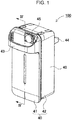
- FIGS. 1 to 10 illustrate a battery pack according to a first exemplary embodiment.
- FIG. 1 is a perspective view that illustrates an appearance of battery pack 100 according to the first exemplary embodiment.
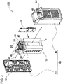
- FIG. 2 is a back perspective view of an appearance of battery pack 100 in FIG. 1 .
- FIG. 3 is an exploded perspective view of battery pack 100 in FIG. 2 .
- FIG. 4 is a cross-sectional view of battery pack 100 in FIG. 1 taken along line IV-IV in FIG. 1 .
- FIG. 5 is an enlarged cross-sectional view of main part that illustrates floating connector 30 of battery pack 100 in FIG. 4 .
- FIG. 6A is a bottom view of floating connector 30.
- FIG. 6B is a side view of floating connector 30.
- FIG. 6C is a plan view of floating connector 30.
- FIG. 6A is a bottom view of floating connector 30.
- FIG. 6B is a side view of floating connector 30.
- FIG. 6C is a plan view of floating connector 30.
- FIG. 6D is a cross-sectional view of floating connector 30 in FIG. 6B taken along line VID-VID in FIG. 6B .
- FIG. 7 is a perspective view that illustrates floating connector 30 in FIG. 5 .
- FIG. 8 is a plan view that illustrates floating connector 30 in FIG. 7 .
- FIG. 9A is a plan view that illustrates an example of cut-off portion 27.
- FIG. 9B is a plan view that illustrates another example of cut-off portion 27.
- FIG. 9C is a plan view that illustrates another example of cut-off portion 27.
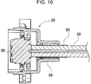
- FIG. 10 is a cross-sectional view that illustrates lead wire 50 according to an example of modification.
- Exterior case 40 has a shape like a box. Exterior case 40 forms a shape of battery pack 100 illustrated in FIGS. 1 and 2 . Exterior case 40 has a space inside exterior case 40. Battery module 10 is disposed in the space. Exterior case 40 is divided into lid 41 and main body 42, as illustrated in FIG. 3 . The main body has the space. Exterior case 40 is made of a light material that has an excellent insulating property, such as a resin. Exterior case 40 may have handle 43 on a top of exterior case 40, and legs 44 on a bottom of exterior case 40, as necessary. Further, exterior case 40 includes a charging terminal and a discharging terminal in a surface of exterior case 40. In the example, exterior case 40 includes charging terminal 45 in a top of exterior case 40, as illustrated in FIG.
- exterior case 40 includes discharging terminal 46 in a bottom of exterior case 40, as illustrated in FIG. 2 .
- the terminals may be each covered with a cover, such as a cap. Consequently, surfaces of the terminals are not exposed.
- charging terminal 45 is covered.
- charging terminal 45 and discharging terminal 46 are separate from each other.
- the present invention is not limited to the configuration.
- the charging terminal and discharging terminal 46 may be integrally made.
- exterior case 40 has depression 47 in a surface of exterior case 40.
- Floating connector 30 is disposed in depression 47. Consequently, floating connector 30 does not protrude from the surface of exterior case 40. Therefore, floating connector 30 is not allowed to accidentally come into contact with an object.
- Exterior case 40 includes opening 48, as illustrated in an exploded perspective view of FIG. 3 , and cross-sectional views of FIGS. 4 and 5 .
- Connector holder 20 is fixed to opening 48.
- Floating connector 30 is disposed in depression 47, as described above.
- Opening 48 is in a bottom of depression 47.
- Battery module 10 is disposed in exterior case 40, as illustrated in a cross-sectional view of FIG. 4 .
- Battery module 10 includes at least one secondary-battery cell 1.
- the secondary batteries are connected with each other in series and in parallel. Consequently, battery module 10 produces predetermined power, and has a predetermined capacity.
- Battery module 10 includes battery holder 11, as illustrated in an exploded perspective view of FIG. 3 .
- Battery holder 11 holds a plurality of secondary-battery cells 1.
- Secondary-battery cells 1 are each cylindrical.
- Battery holder 11 includes cell retainers. The cell retainers retain ends of respective secondary-battery cells 1. The cell retainers are each cylindrical. When secondary-battery cells 1 are disposed in battery holder 11, surfaces of ends of secondary-battery cells 1 are out of battery holder 11.
- the surfaces of ends are welded to lead sheets.
- the lead sheets connect secondary-battery cells 1 with each other in series and in parallel. In an example in FIG. 3 , 28 secondary-battery cells 1 are connected with each other. More specifically, four parallel sets of seven secondary-battery cells 1 in series are connected with each other. Shapes and an arrangement of the lead sheets depend on parallel and series connections of secondary-battery cells 1.
- the lead sheets are made of a metal that has excellent conductivity.
- the lead sheets are connected with surfaces of ends of secondary-battery cells 1 by spot welding, for example.
- the lead sheets are connected with circuit board 3.
- Circuit board 3 is disposed on a side of battery holder 11.
- Circuit board 3 includes a circuit that charges and discharges secondary-battery cells 1, and a protection circuit.
- Each of secondary-battery cells 1 is a cylindrical battery that includes a cylindrical exterior can.
- Secondary-battery cells 1 may be lithium-ion secondary batteries, nickel metal hydride secondary batteries, or nickelcadmium secondary batteries, for example. Lithium-ion secondary batteries are especially preferable because lithium-ion secondary batteries have high energy efficiency per unit of volume.
- the lead sheets connect electrodes of surfaces of ends of the plurality of secondary-battery cells with each other. Consequently, the plurality of secondary-battery cells are connected with each other in series and in parallel.
- the present invention is not limited to secondary-battery cells that are cylindrical. Prismatic (rectangular) batteries or pouch batteries may be used.
- the waterproof container may be a bag.
- the waterproof bag is made of a transparent resin, such as polyethylene. If a waterproof function is not necessary for battery module 10, the waterproof bag may be eliminated.
- Exterior case 40 exposes connector holder 20 through opening 48 of exterior case 40.
- connector holder 20 is fixed to exterior case 40.
- Connector holder 20 has two main surfaces.
- First main surface 21 is one of the two main surfaces.
- First main surface 21 is exposed through opening 48 of exterior case 40.
- Second main surface 22 is opposite first main surface 21.
- Second main surface 22 faces an inside of exterior case 40.
- Floating connector 30 is attached to connector holder 20.
- Floating connector 30 is a terminal that is able to be connected with a device to which battery pack 100 supplies electrical energy.
- floating connector 30 is a discharging terminal. More specifically, exterior case 40 exposes part of a surface of floating connector 30.
- Discharging terminal 46 is made or disposed on the exposed part of a surface of floating connector 30. If magnetism is used to connect floating connector 30 with a device to which battery pack 100 supplies electrical energy, a magnet or a metallic piece is attached to discharging terminal 46.
- the magnetic connection allows floating connector 30 to be positioned at an appropriate position. Further, the magnetic connection allows floating connector 30 to continue to be connected with a device to which battery pack 100 supplies electrical energy.
- Floating connector 30 has connector base 32 on a back-surface side of floating connector 30.
- the back-surface side is an inner surface of floating connector 30 that is opposite the exposed part of a surface of floating connector 30.
- Connector base 32 has a shape like a disk, for example.
- Lead wire 50 is connected with substantially a center of connector base 32.
- Lead wire 50 is fixed to substantially a center of floating connector 30.
- Lead wire 50 is substantially perpendicular to floating connector 30.
- Lead wire 50 extends through an inside of exterior case 40 and is connected with circuit board 3.
- FIG. 6A is a bottom view of connector holder 20 connected with floating connector 30.
- FIG. 6B is a side view of connector holder 20 connected with floating connector 30.
- FIG. 6C is a plan view of connector holder 20 connected with floating connector 30.
- FIG. 6D is a cross-sectional view of connector holder 20 connected with floating connector 30.
- connector holder 20 has frame 23 that is rectangular.
- Connector holder 20 is open on a first-main-surface-21 side (a bottom side) of connector holder 20.
- floating connector 30 is exposed.
- holding sheet 24 is fixed to an inner surface of frame 23.
- Holding sheet 24 is a flat sheet.
- Holding sheet 24 has an opening in a center of holding sheet 24.
- Floating connector 30 is disposed in the opening.
- Connecting component 25 is between floating connector 30 and holding sheet 24.
- Connecting component 25 is flexible, and is a bellows or rubber, for example.
- Connecting component 25 connects floating connector 30 with holding sheet 24. Since connecting component 25 deforms, an orientation of floating connector 30 is variable. As described above, floating connector 30 is not completely fixed, but is allowed to slightly move. Therefore, when battery pack 100 is connected with a device to which battery pack 100 supplies electrical energy, a position of floating connector 30 relative to a connector of the device to which battery pack 100 supplies electrical energy is adjustable, and an orientation of floating connector 30 is adjustable. Therefore, battery pack 100 is surely connected with the device to which battery pack 100 supplies electrical energy.
- Floating connector 30 is held by connector holder 20 in such a manner that floating connector 30 floats in such a manner that an orientation of floating connector 30 is variable. Further, preferably, floating connector 30 has a restoring force that allows floating connector 30 to return to an original state when an external force is not applied to floating connector 30.
- floating connector 30 is held horizontally. That is to say, preferably, floating connector 30 is held substantially parallel to a bottom of exterior case 40, and floating connector 30 is held at substantially a center of the opening of holding sheet 24. Consequently, when battery pack 100 is connected with a device to which battery pack 100 supplies electrical energy, floating connector 30 is easily connected with a connector of the device to which battery pack 100 supplies electrical energy. In an example in FIG. 5 , floating connector 30 is parallel to a plane of holding sheet 24.
- Connector holder 20 and floating connector 30 may be standardized components. Consequently, a conventional floating connector that includes a lead wire becomes usable, and an orientation of the conventional floating connector becomes adjustable. Consequently, the orientation of the conventional floating connector is held at a central original orientation.
- connector holder 20 is standardized and has depression 47.
- floating connector 30 is standardized and includes lead wire 50 connected with floating connector 30. Floating connector 30 is disposed in depression 47.
- frame 23 of connector holder 20 is rectangular.
- a frame may be cylindrical, for example.
- Connector holder 20 is closed on a second-main-surface-22 side (a top side) of connector holder 20.
- Guide pipe 26 connects with substantially a center of the second-main-surface-22 side of connector holder 20.
- Guide pipe 26 is cylindrical.
- Frame 23 and guide pipe (tube) 26 are made in such a manner that a space in frame 23 adjoins an inner surface of guide pipe 26.
- Frame 23 and guide pipe 26 are integrally made.
- Guide pipe 26 is fixed to second main surface 22 of connector holder 20.
- Guide pipe 26 is substantially perpendicular to second main surface 22 of connector holder 20.
- Lead wire 50 fixed to a back surface of connector holder 20 is inserted in guide pipe 26. Consequently, lead wire 50 is substantially vertically held. Therefore, lead wire 50 does not apply bias to floating connector 30 connected with lead wire 50.
- lead wire 50 connected with floating connector 30 interferes with the floating mechanism.
- Battery packs need to produce high power in recent years. Consequently, large electric current for charging or discharging flows through a lead wire of each of the battery packs. Therefore, resistances of the lead wires tend to become lower, and thus diameters of the lead wires tend to become larger. Consequently, the lead wires become less flexible. Consequently, a lead wire in some orientation or in some state may apply a force to a floating connector.
- a lead wire whose end is connected with a floating connector may push or pull the floating connector. That is to say, although a floating connector is used, the floating connector receives an external force from a lead wire connected with the floating connector.
- the floating connector may become inclined from an original state, or may become out of a center. Further, even if an external force is applied to a floating connector, a restoring force of a floating mechanism naturally allows the floating connector to return to an original state after the external force vanishes. For example, even if a floating connector is pushed, a restoring force of a floating mechanism naturally allows the floating connector to return to an original state after the floating connector ceases to be pushed. However, a lead wire may apply a force to the floating connector, as described above. Consequently, the restoring force is weakened. Consequently, the floating connector may not return to the original state. As described above, a lead wire connected with a floating connector may interfere with a floating function.
- connector holder 20 has guide pipe 26 on a second-main-surface-22 side of connector holder 20, as illustrated in FIGS. 5 , 7 , and 8 .
- Guide pipe 26 is cylindrical and surrounds lead wire 50.
- Guide pipe 26 is substantially perpendicular to the second-main-surface-22 side. Consequently, lead wire 50 that extends from an inner surface of floating connector 30 and extends substantially perpendicularly to the inner surface passes through guide pipe 26. Therefore, floating connector 30 is horizontally held.
- Lead wire 50 is especially less flexible near a connection between lead wire 50 and floating connector 30. Therefore, the floating connector is likely to be influenced by an angle of part of the lead wire that is near the floating connector. For example, in a comparative example illustrated in FIG.
- guide pipe 26 is disposed near a connection between lead wire 50 and floating connector 30, as illustrated in FIG. 5 .
- Guide pipe 26 holds lead wire 50 in such a manner that part of lead wire 50 that is near the connection is almost vertical. Consequently, an original state of floating connector 30 is almost horizontal. In other words, even if lead wire 50 applies a force to floating connector 30, guide pipe 26 adjusts an orientation of floating connector 30. Consequently, the orientation of floating connector 30 is horizontally held near the connection between lead wire 50 and floating connector 30.
- an inner diameter of guide pipe 26 is larger than an outer diameter of lead wire 50, as illustrated in FIGS. 5 , 6D , and 7 . Consequently, guide pipe 26 does not interfere with the floating mechanism of floating connector 30. Since an inner diameter of guide pipe 26 is larger than an outer diameter of lead wire 50, a space is formed around lead wire 50. Therefore, lead wire 50 is allowed to slightly move or deform in the space. Therefore, floating connector 30 connected with lead wire 50 is allowed to become inclined or tilt. Therefore, the floating mechanism surely operates.
- friction decreasing mechanisms are disposed that decrease friction between a surface of lead wire 50 and an inner surface of guide pipe 26.
- cut-off portion 27 is an example of the friction decreasing mechanisms.
- a shape of a cross section of guide pipe 26 that is cylindrical is a circle that has cut-off portion 27. Such a configuration decreases an area of part of a surface of lead wire 50 that is in contact with an inner surface of guide pipe 26 through which lead wire 50 passes.
- Ribs 28 may be made on cut-off portion 27. Ribs 28 reinforce guide pipe 26. In an example illustrated in FIGS. 7 and 8 , three ribs 28 outward protrude from cut-off portion 27. Guide pipe 26 has a circular cross section. In a plan view, ends of ribs 28 are along the circular cross section. Consequently, guide pipe 26 that has cut-off portion 27 becomes strong.
- an edge of cut-off portion 27 has a radius of curvature that is larger than a radius of curvature of a circular cross section of guide pipe 26.
- a surface of an end of cut-off portion 27A of guide pipe 26A has a shape like a straight line whose radius of curvature is infinity, as illustrated in FIG. 9A . Consequently, an area of part of a surface of the lead wire that is in contact with an inner surface of guide pipe 26A is smaller than an area of part of a surface of the lead wire that is in contact with an inner surface of guide pipe 26 that is circular.
- the present invention is not limited to a cut-off portion that has a shape like a straight line. A cut-off portion may be curved.
- guide pipe 26B has cut-off portion 27B that is curved, as illustrated in FIG. 9B .
- an area of part of a surface of the lead wire that is in contact with an inner surface of guide pipe 26B is smaller than an area of part of a surface of the lead wire that is in contact with an inner surface of guide pipe 26B that is circular.
- Guide pipe 26B provides a space where lead wire 50 is able to move. The space is larger than a space where lead wire 50 is able to move provided by a guide pipe that has a cut-off portion that has a shape like a straight line. Therefore, floating connector 30 is allowed to become more inclined.
- the cut-off portion is convex.
- a cut-off portion may be concave, as illustrated in FIG. 9C . That is to say, cut-off portion 27C may be concave, and may protrude toward an inside of a cylindrical shape of guide pipe 26. In that case, a radius of curvature of cut-off portion 27C is smaller than a radius of curvature of a circle of guide pipe 26.
- an area of part of a surface of the lead wire that is in contact with an inner surface of guide pipe 26C is even smaller than an area of part of a surface of the lead wire that is in contact with an inner surface of guide pipe 26.
- a position of cut-off portion 27 depends on a position of circuit board 3 to which lead wire 50 is fixed.
- an edge of guide pipe 26 has cut-off portion 27 at a position of the edge that is far from circuit board 3.
- the configuration especially allows a length of lead wire 50 to be longer than a minimum length required to connect floating connector 30 with circuit board 3. Consequently, lead wire 50 becomes easily handled. Consequently, assembly becomes more efficient. Further, lead wire 50 is allowed to deform more. Consequently, floating connector 30 becomes surely likely to be inclined.
- a length of the lead wire is longer than a minimum length required to connect the floating connector with the circuit board. That is to say, the lead wire is curved.
- part of the lead wire is in contact with an inner surface of the guide pipe in a direction in which the lead wire is curved.
- An edge of guide pipe 26 has cut-off portion 27 at a position of the edge that is far from circuit board 3. Consequently, lead wire 50 is in contact with cut-off portion 27. Cut-off portion 27 decreases an area of part of a surface of lead wire 50 that is in contact with an inner surface of the guide pipe. Consequently, lead wire 50 smoothly moves on an inner surface of the guide pipe.
- cut-off portion 27 is parallel to an edge of circuit board 3.
- cut-off portion 27A is parallel to an edge of circuit board 3, as illustrated in FIG. 9A .
- cut-off portion 27 is inclined in a direction in which lead wire 50 extends from circuit board 3, as illustrated in FIG. 8 .
- lead wire 50 is connected with circuit board 3 at a left side of a top of circuit board 3.
- Lead wire 50 rightward extends from circuit board 3.
- lead wire 50 is curved in a shape like a letter "U”.
- lead wire 50 is connected with floating connector 30. That is to say, lead wire 50 rightward extends from circuit board 3.
- lead wire 50 is curved, and is connected with floating connector 30.
- lead wire 50 is likely to be in contact with a right inner surface of guide pipe 26. Further, as described above, lead wire 50 is long. Therefore, lead wire 50 that extends from circuit board 3 passes guide pipe 26. Further, lead wire 50 is curved, and is connected with floating connector 30. In that case, lead wire 50 is likely to be in contact with an upper inner surface of guide pipe 26. In light of the above description, cut-off portion 27 is likely to be in contact with an upper side and a right side of guide pipe 26. Therefore, the cut-off portion is inclined in a direction in which lead wire 50 extends from circuit board 3. For example, the cut-off portion is inclined downward toward a right in FIG. 8 .
- cut-off portion 27 is positioned in such a manner that lead wire 50 that extends from circuit board 3 rubs against cut-off portion 27. Consequently, lead wire 50 is surely in contact with cut-off portion 27. Consequently, lead wire 50 smoothly moves on the guide pipe. Consequently, floating operation becomes smooth.
- tape 52 that has a smooth surface.
- Tape 52 may be wound around lead wire 50, as illustrated in a cross-sectional view of FIG. 10 . Consequently, frictional resistance of a surface of lead wire 50 decreases. Therefore, floating operation is more reliable.
- Tape 52 is made of a material that has a low coefficient of friction, such as polypropylene.
- Lead wire 50 includes not only one lead wire, but also may include a plurality of lead wires.
- the plurality of lead wires may be made of different materials. Further, the plurality of lead wires may have different thicknesses. In that case, the plurality of lead wires are tied into a bundle with tape 52. Consequently, the plurality of lead wires are easily handled in exterior case 40. Consequently, assembly and maintenance become more efficient. Further, tape 52 is wound around part of lead wire 50 that is in contact with guide pipe 26. Consequently, lead wire 50 smoothly moves on guide pipe 26, as described above. Consequently, frictional resistance decreases. Consequently, floating connector 30 is allowed to surely become inclined.
- Connector holder 20 also has fixing portions 29 that allow connector holder 20 to be inserted into opening 48 of exterior case 40 from an inside of exterior case 40, and are used to fix connector holder 20 to opening 48 of exterior case 40 from an inside of exterior case 40. Consequently, a relay connector is not necessary.
- the relay connector is necessary if connector holder 20 is fixed to exterior case 40 from an outside of exterior case 40. Therefore, lead wire 50 is preliminarily welded to floating connector 30. Then lead wire 50 welded to floating connector 30 is directly connected with circuit board 3.
- floating connector 130 is directly fixed to exterior case 140 from an outside of exterior case 140.
- Floating connector 130 is directly fixed to exterior case 140 with screws 160.
- a relay connector is necessary to electrically connect a lead wire in exterior case 140. Consequently, a cost increases. If a battery pack needs to produce high power and large electric current flows, a connector for large electric current is necessary. If a battery pack needs to be waterproof, a waterproof connector is used. Consequently, a cost further increases.
- fixing portions 29 are used to fix connector holder 20 to exterior case 40 from an inside of exterior case 40. Therefore, such a relay connector is not necessary. Further, exterior case 40 is assembled in a last step of assembly. Therefore, the assembly becomes efficient.
- Known structures for fixing are appropriately used for fixing portions 29. For example, screw holes are used to screw connector holder 20 to exterior case 40 from an inside of exterior case 40 with screws 60, as illustrated in FIG. 3 .
- battery module 10 and circuit board 3 are arranged in exterior case 40.
- Lead wire 50 extends from circuit board 3.
- Lead wire 50 is inserted into guide pipe 26.
- Guide pipe 26 is cylindrical.
- Guide pipe 26 is part of connector holder 20, and is on a second-main-surface-22 side of connector holder 20.
- lead wire 50 is connected with floating connector 30.
- connector holder 20 is inserted into opening 48 of exterior case 40 from an inside of exterior case 40.
- connector holder 20 is fixed to opening 48 of exterior case 40 from an inside of exterior case 40.
- exterior case 40 is closed. Consequently, lead wire 50 passes through guide pipe 26.
- a battery pack and a production method for a battery pack according to an aspect of the present invention are suitably used as power sources for electric tools, electric bicycles, electric motorcycles, hybrid electric vehicles, and electric vehicles. Further, the battery pack and the production method for a battery pack according to an aspect of the present invention are suitably used as power sources used to store electricity at home and stores.
Landscapes
- Engineering & Computer Science (AREA)
- Manufacturing & Machinery (AREA)
- Chemical & Material Sciences (AREA)
- Chemical Kinetics & Catalysis (AREA)
- Electrochemistry (AREA)
- General Chemical & Material Sciences (AREA)
- Microelectronics & Electronic Packaging (AREA)
- Battery Mounting, Suspending (AREA)
- Details Of Connecting Devices For Male And Female Coupling (AREA)
Applications Claiming Priority (2)
| Application Number | Priority Date | Filing Date | Title |
|---|---|---|---|
| JP2017145920 | 2017-07-27 | ||
| PCT/JP2018/027414 WO2019021979A1 (fr) | 2017-07-27 | 2018-07-23 | Bloc-batterie et son procédé de fabrication |
Publications (3)
| Publication Number | Publication Date |
|---|---|
| EP3660946A1 true EP3660946A1 (fr) | 2020-06-03 |
| EP3660946A4 EP3660946A4 (fr) | 2020-07-08 |
| EP3660946B1 EP3660946B1 (fr) | 2026-02-25 |
Family
ID=65040250
Family Applications (1)
| Application Number | Title | Priority Date | Filing Date |
|---|---|---|---|
| EP18838494.5A Active EP3660946B1 (fr) | 2017-07-27 | 2018-07-23 | Bloc-batterie et son procédé de fabrication |
Country Status (6)
| Country | Link |
|---|---|
| US (1) | US11424516B2 (fr) |
| EP (1) | EP3660946B1 (fr) |
| JP (1) | JP7112401B2 (fr) |
| AU (1) | AU2018307011B2 (fr) |
| NZ (1) | NZ761688A (fr) |
| WO (1) | WO2019021979A1 (fr) |
Families Citing this family (5)
| Publication number | Priority date | Publication date | Assignee | Title |
|---|---|---|---|---|
| CN110571581A (zh) * | 2019-10-10 | 2019-12-13 | 上海先惠自动化技术股份有限公司 | 一种高压接头自动对接机构 |
| CN110556653A (zh) * | 2019-10-10 | 2019-12-10 | 上海先惠自动化技术股份有限公司 | 一种数据线接头自动对接机构 |
| JP6865258B1 (ja) * | 2019-11-06 | 2021-04-28 | 日本端子株式会社 | コネクタ接続構造 |
| NO346040B1 (en) * | 2020-05-28 | 2022-01-17 | Griff Aviation As | A battery connector |
| US12160127B2 (en) | 2021-12-09 | 2024-12-03 | Honda Motor Co., Ltd. | Battery terminal fixing apparatus and method for power equipment |
Family Cites Families (21)
| Publication number | Priority date | Publication date | Assignee | Title |
|---|---|---|---|---|
| US5144217A (en) * | 1989-03-03 | 1992-09-01 | Black & Decker Inc. | Cordless tool battery housing and charging system |
| JPH0251616A (ja) | 1988-08-16 | 1990-02-21 | Canon Inc | フローティングコネクタ |
| DE4309034C2 (de) * | 1993-03-20 | 1996-07-18 | Braun Ag | Elektrogerät |
| JP2006147115A (ja) * | 2004-11-25 | 2006-06-08 | Sanyo Electric Co Ltd | 光ディスク装置 |
| JP5110777B2 (ja) * | 2005-06-29 | 2012-12-26 | 三洋電機株式会社 | パック電池 |
| JP4933325B2 (ja) | 2007-03-29 | 2012-05-16 | 原田工業株式会社 | 接続端子構造 |
| DE102009012184A1 (de) * | 2009-02-27 | 2010-09-02 | Andreas Stihl Ag & Co. Kg | Tragbares, handgeführtes Elektrogerät mit einem Akkupack |
| DE102009012180A1 (de) * | 2009-02-27 | 2010-09-02 | Andreas Stihl Ag & Co. Kg | Akkupack für ein Elektrowerkzeug |
| JP5593894B2 (ja) * | 2009-07-30 | 2014-09-24 | スズキ株式会社 | 電動の乗り物に脱着されるバッテリパックとこのバッテリパックを備える電動の乗り物 |
| JP5573471B2 (ja) * | 2010-08-05 | 2014-08-20 | スズキ株式会社 | バッテリパック |
| US8765297B2 (en) * | 2011-01-04 | 2014-07-01 | Exide Technologies | Advanced graphite additive for enhanced cycle-life of lead-acid batteries |
| JP2012205371A (ja) * | 2011-03-24 | 2012-10-22 | Sanyo Electric Co Ltd | 携帯式電源装置 |
| WO2014162963A1 (fr) * | 2013-04-03 | 2014-10-09 | Necエナジーデバイス株式会社 | Module de batteries |
| JP6651457B2 (ja) | 2014-11-07 | 2020-02-19 | 三洋電機株式会社 | 電源装置 |
| EP3304616B1 (fr) * | 2015-06-05 | 2022-08-03 | Milwaukee Electric Tool Corporation | Élément de support pour boîtier supérieur de bloc-batterie |
| EP3162513B1 (fr) * | 2015-10-30 | 2019-04-17 | Black & Decker Inc. | Moteur sans balai à puissance élevée |
| CN206441961U (zh) * | 2016-09-21 | 2017-08-25 | 蔚来汽车有限公司 | 电动汽车液冷电池包的连接器 |
| WO2018204800A1 (fr) * | 2017-05-04 | 2018-11-08 | Regents Of The University Of Minnesota | Compositions de nitrure de fer |
| JP7177652B2 (ja) * | 2018-10-11 | 2022-11-24 | 株式会社マキタ | 背負式機器 |
| US12230820B2 (en) * | 2019-01-09 | 2025-02-18 | Byd Company Limited | Power battery pack and electric vehicle |
| US11477885B2 (en) * | 2020-09-30 | 2022-10-18 | Inventus Power, Inc. | Redundant trace fuse for a conformal wearable battery |
-
2018
- 2018-07-23 NZ NZ761688A patent/NZ761688A/en unknown
- 2018-07-23 EP EP18838494.5A patent/EP3660946B1/fr active Active
- 2018-07-23 JP JP2019532578A patent/JP7112401B2/ja active Active
- 2018-07-23 US US16/633,054 patent/US11424516B2/en active Active
- 2018-07-23 AU AU2018307011A patent/AU2018307011B2/en active Active
- 2018-07-23 WO PCT/JP2018/027414 patent/WO2019021979A1/fr not_active Ceased
Also Published As
| Publication number | Publication date |
|---|---|
| US11424516B2 (en) | 2022-08-23 |
| AU2018307011B2 (en) | 2024-02-08 |
| JP7112401B2 (ja) | 2022-08-03 |
| US20200235366A1 (en) | 2020-07-23 |
| EP3660946B1 (fr) | 2026-02-25 |
| JPWO2019021979A1 (ja) | 2020-06-11 |
| WO2019021979A1 (fr) | 2019-01-31 |
| NZ761688A (en) | 2026-01-30 |
| EP3660946A4 (fr) | 2020-07-08 |
| AU2018307011A1 (en) | 2020-02-27 |
Similar Documents
| Publication | Publication Date | Title |
|---|---|---|
| EP3660946B1 (fr) | Bloc-batterie et son procédé de fabrication | |
| US9209492B2 (en) | Battery pack | |
| CN113826270B (zh) | 电池组、电子装置及车辆 | |
| KR100833745B1 (ko) | 이차 전지 | |
| US20050089753A1 (en) | Secondary battery | |
| CN110168799A (zh) | 电池模块 | |
| US11205817B2 (en) | Battery pack | |
| EP3787063B1 (fr) | Bloc-batterie | |
| US10541452B2 (en) | Battery pack including circuit board having protruding surface | |
| KR20170083311A (ko) | 배터리 팩 | |
| EP4109662A1 (fr) | Module de batterie, bloc-batterie le comprenant et véhicule | |
| EP3660943B1 (fr) | Bloc batterie et son procédé de production | |
| CN110612617A (zh) | 电气组件及包括该电气组件的电池组 | |
| US20180013121A1 (en) | Secondary battery | |
| WO2021193206A1 (fr) | Installation de stockage électrique | |
| US11264146B2 (en) | Flat cable with improved short-circuit prevention function | |
| KR102913933B1 (ko) | 방식 부재가 구비된 버스 바 및 이를 포함하는 배터리 모듈 | |
| KR102248230B1 (ko) | 이차전지 모듈 | |
| KR102714029B1 (ko) | 배터리 모듈, 이를 포함하는 배터리 팩 및 자동차 | |
| CN104037366A (zh) | 可再充电电池组 | |
| KR20220074593A (ko) | 배터리 모듈, 배터리 팩, 및 전력 저장 장치 | |
| EP4510370A1 (fr) | Module de batterie |
Legal Events
| Date | Code | Title | Description |
|---|---|---|---|
| STAA | Information on the status of an ep patent application or granted ep patent |
Free format text: STATUS: THE INTERNATIONAL PUBLICATION HAS BEEN MADE |
|
| PUAI | Public reference made under article 153(3) epc to a published international application that has entered the european phase |
Free format text: ORIGINAL CODE: 0009012 |
|
| STAA | Information on the status of an ep patent application or granted ep patent |
Free format text: STATUS: REQUEST FOR EXAMINATION WAS MADE |
|
| 17P | Request for examination filed |
Effective date: 20200217 |
|
| AK | Designated contracting states |
Kind code of ref document: A1 Designated state(s): AL AT BE BG CH CY CZ DE DK EE ES FI FR GB GR HR HU IE IS IT LI LT LU LV MC MK MT NL NO PL PT RO RS SE SI SK SM TR |
|
| AX | Request for extension of the european patent |
Extension state: BA ME |
|
| A4 | Supplementary search report drawn up and despatched |
Effective date: 20200609 |
|
| RIC1 | Information provided on ipc code assigned before grant |
Ipc: H01M 10/04 20060101ALI20200603BHEP Ipc: H01R 12/91 20110101ALI20200603BHEP Ipc: H01M 2/10 20060101AFI20200603BHEP Ipc: H01M 2/06 20060101ALI20200603BHEP Ipc: H01M 10/42 20060101ALI20200603BHEP |
|
| DAV | Request for validation of the european patent (deleted) | ||
| DAX | Request for extension of the european patent (deleted) | ||
| STAA | Information on the status of an ep patent application or granted ep patent |
Free format text: STATUS: EXAMINATION IS IN PROGRESS |
|
| 17Q | First examination report despatched |
Effective date: 20230123 |
|
| REG | Reference to a national code |
Ref country code: DE Ref legal event code: R079 Free format text: PREVIOUS MAIN CLASS: H01M0002100000 Ipc: H01M0010040000 Ref country code: DE Ref legal event code: R079 Ref document number: 602018089432 Country of ref document: DE Free format text: PREVIOUS MAIN CLASS: H01M0002100000 Ipc: H01M0010040000 |
|
| RIC1 | Information provided on ipc code assigned before grant |
Ipc: H01M 10/04 20060101AFI20250714BHEP Ipc: H01M 50/209 20210101ALI20250714BHEP Ipc: H01M 50/271 20210101ALI20250714BHEP Ipc: H01M 50/176 20210101ALI20250714BHEP Ipc: H01R 12/91 20110101ALI20250714BHEP Ipc: H01M 10/42 20060101ALI20250714BHEP |
|
| GRAJ | Information related to disapproval of communication of intention to grant by the applicant or resumption of examination proceedings by the epo deleted |
Free format text: ORIGINAL CODE: EPIDOSDIGR1 |
|
| GRAP | Despatch of communication of intention to grant a patent |
Free format text: ORIGINAL CODE: EPIDOSNIGR1 |
|
| GRAP | Despatch of communication of intention to grant a patent |
Free format text: ORIGINAL CODE: EPIDOSNIGR1 |
|
| STAA | Information on the status of an ep patent application or granted ep patent |
Free format text: STATUS: GRANT OF PATENT IS INTENDED |
|
| INTG | Intention to grant announced |
Effective date: 20250918 |
|
| RAP3 | Party data changed (applicant data changed or rights of an application transferred) |
Owner name: SANYO ELECTRIC CO., LTD. |
|
| RAP1 | Party data changed (applicant data changed or rights of an application transferred) |
Owner name: PANASONIC ENERGY CO., LTD. |
|
| GRAS | Grant fee paid |
Free format text: ORIGINAL CODE: EPIDOSNIGR3 |
|
| GRAA | (expected) grant |
Free format text: ORIGINAL CODE: 0009210 |
|
| STAA | Information on the status of an ep patent application or granted ep patent |
Free format text: STATUS: THE PATENT HAS BEEN GRANTED |
|
| AK | Designated contracting states |
Kind code of ref document: B1 Designated state(s): AL AT BE BG CH CY CZ DE DK EE ES FI FR GB GR HR HU IE IS IT LI LT LU LV MC MK MT NL NO PL PT RO RS SE SI SK SM TR |
|
| REG | Reference to a national code |
Ref country code: CH Ref legal event code: F10 Free format text: ST27 STATUS EVENT CODE: U-0-0-F10-F00 (AS PROVIDED BY THE NATIONAL OFFICE) Effective date: 20260225 Ref country code: GB Ref legal event code: FG4D |
|
| REG | Reference to a national code |
Ref country code: DE Ref legal event code: R096 Ref document number: 602018089432 Country of ref document: DE |
|
| REG | Reference to a national code |
Ref country code: IE Ref legal event code: FG4D |