EP3661472B1 - Appareil à tige de traction, compact, réglable rapidement, autobloquant, destiné à être utilisé lors d'interventions chirurgicales - Google Patents
Appareil à tige de traction, compact, réglable rapidement, autobloquant, destiné à être utilisé lors d'interventions chirurgicales Download PDFInfo
- Publication number
- EP3661472B1 EP3661472B1 EP18762228.7A EP18762228A EP3661472B1 EP 3661472 B1 EP3661472 B1 EP 3661472B1 EP 18762228 A EP18762228 A EP 18762228A EP 3661472 B1 EP3661472 B1 EP 3661472B1
- Authority
- EP
- European Patent Office
- Prior art keywords
- spindle
- traction unit
- longitudinal axis
- drive
- contact surface
- Prior art date
- Legal status (The legal status is an assumption and is not a legal conclusion. Google has not performed a legal analysis and makes no representation as to the accuracy of the status listed.)
- Active
Links
Images



Classifications
-
- A—HUMAN NECESSITIES
- A61—MEDICAL OR VETERINARY SCIENCE; HYGIENE
- A61G—TRANSPORT, PERSONAL CONVEYANCES, OR ACCOMMODATION SPECIALLY ADAPTED FOR PATIENTS OR DISABLED PERSONS; OPERATING TABLES OR CHAIRS; CHAIRS FOR DENTISTRY; FUNERAL DEVICES
- A61G13/00—Operating tables; Auxiliary appliances therefor
- A61G13/10—Parts, details or accessories
- A61G13/12—Rests specially adapted therefor; Arrangements of patient-supporting surfaces
- A61G13/128—Rests specially adapted therefor; Arrangements of patient-supporting surfaces with mechanical surface adaptations
- A61G13/129—Rests specially adapted therefor; Arrangements of patient-supporting surfaces with mechanical surface adaptations having surface parts for adaptation of the size, e.g. for extension or reduction
-
- A—HUMAN NECESSITIES
- A61—MEDICAL OR VETERINARY SCIENCE; HYGIENE
- A61G—TRANSPORT, PERSONAL CONVEYANCES, OR ACCOMMODATION SPECIALLY ADAPTED FOR PATIENTS OR DISABLED PERSONS; OPERATING TABLES OR CHAIRS; CHAIRS FOR DENTISTRY; FUNERAL DEVICES
- A61G13/00—Operating tables; Auxiliary appliances therefor
- A61G13/0036—Orthopaedic operating tables
- A61G13/0081—Orthopaedic operating tables specially adapted for hip surgeries
-
- A—HUMAN NECESSITIES
- A61—MEDICAL OR VETERINARY SCIENCE; HYGIENE
- A61B—DIAGNOSIS; SURGERY; IDENTIFICATION
- A61B17/00—Surgical instruments, devices or methods
- A61B17/56—Surgical instruments or methods for treatment of bones or joints; Devices specially adapted therefor
- A61B17/58—Surgical instruments or methods for treatment of bones or joints; Devices specially adapted therefor for osteosynthesis, e.g. bone plates, screws or setting implements
- A61B17/60—Surgical instruments or methods for treatment of bones or joints; Devices specially adapted therefor for osteosynthesis, e.g. bone plates, screws or setting implements for external osteosynthesis, e.g. distractors, contractors
- A61B17/66—Alignment, compression or distraction mechanisms
-
- A—HUMAN NECESSITIES
- A61—MEDICAL OR VETERINARY SCIENCE; HYGIENE
- A61B—DIAGNOSIS; SURGERY; IDENTIFICATION
- A61B17/00—Surgical instruments, devices or methods
- A61B17/56—Surgical instruments or methods for treatment of bones or joints; Devices specially adapted therefor
- A61B17/58—Surgical instruments or methods for treatment of bones or joints; Devices specially adapted therefor for osteosynthesis, e.g. bone plates, screws or setting implements
- A61B17/88—Osteosynthesis instruments; Methods or means for implanting or extracting internal or external fixation devices
- A61B17/8869—Tensioning devices
-
- A—HUMAN NECESSITIES
- A61—MEDICAL OR VETERINARY SCIENCE; HYGIENE
- A61B—DIAGNOSIS; SURGERY; IDENTIFICATION
- A61B90/00—Instruments, implements or accessories specially adapted for surgery or diagnosis and not covered by any of the groups A61B1/00 - A61B50/00, e.g. for luxation treatment or for protecting wound edges
- A61B90/10—Instruments, implements or accessories specially adapted for surgery or diagnosis and not covered by any of the groups A61B1/00 - A61B50/00, e.g. for luxation treatment or for protecting wound edges for stereotaxic surgery, e.g. frame-based stereotaxis
- A61B90/14—Fixators for body parts, e.g. skull clamps; Constructional details of fixators, e.g. pins
-
- A—HUMAN NECESSITIES
- A61—MEDICAL OR VETERINARY SCIENCE; HYGIENE
- A61G—TRANSPORT, PERSONAL CONVEYANCES, OR ACCOMMODATION SPECIALLY ADAPTED FOR PATIENTS OR DISABLED PERSONS; OPERATING TABLES OR CHAIRS; CHAIRS FOR DENTISTRY; FUNERAL DEVICES
- A61G13/00—Operating tables; Auxiliary appliances therefor
- A61G13/0036—Orthopaedic operating tables
-
- A—HUMAN NECESSITIES
- A61—MEDICAL OR VETERINARY SCIENCE; HYGIENE
- A61G—TRANSPORT, PERSONAL CONVEYANCES, OR ACCOMMODATION SPECIALLY ADAPTED FOR PATIENTS OR DISABLED PERSONS; OPERATING TABLES OR CHAIRS; CHAIRS FOR DENTISTRY; FUNERAL DEVICES
- A61G13/00—Operating tables; Auxiliary appliances therefor
- A61G13/10—Parts, details or accessories
- A61G13/12—Rests specially adapted therefor; Arrangements of patient-supporting surfaces
- A61G13/1205—Rests specially adapted therefor; Arrangements of patient-supporting surfaces for specific parts of the body
- A61G13/123—Lower body, e.g. pelvis, hip, buttocks
-
- A—HUMAN NECESSITIES
- A61—MEDICAL OR VETERINARY SCIENCE; HYGIENE
- A61G—TRANSPORT, PERSONAL CONVEYANCES, OR ACCOMMODATION SPECIALLY ADAPTED FOR PATIENTS OR DISABLED PERSONS; OPERATING TABLES OR CHAIRS; CHAIRS FOR DENTISTRY; FUNERAL DEVICES
- A61G13/00—Operating tables; Auxiliary appliances therefor
- A61G13/10—Parts, details or accessories
- A61G13/12—Rests specially adapted therefor; Arrangements of patient-supporting surfaces
- A61G13/1205—Rests specially adapted therefor; Arrangements of patient-supporting surfaces for specific parts of the body
- A61G13/125—Ankles or feet
-
- A—HUMAN NECESSITIES
- A61—MEDICAL OR VETERINARY SCIENCE; HYGIENE
- A61G—TRANSPORT, PERSONAL CONVEYANCES, OR ACCOMMODATION SPECIALLY ADAPTED FOR PATIENTS OR DISABLED PERSONS; OPERATING TABLES OR CHAIRS; CHAIRS FOR DENTISTRY; FUNERAL DEVICES
- A61G13/00—Operating tables; Auxiliary appliances therefor
- A61G13/10—Parts, details or accessories
- A61G13/12—Rests specially adapted therefor; Arrangements of patient-supporting surfaces
- A61G13/128—Rests specially adapted therefor; Arrangements of patient-supporting surfaces with mechanical surface adaptations
- A61G13/1285—Rests specially adapted therefor; Arrangements of patient-supporting surfaces with mechanical surface adaptations having modular surface parts, e.g. being replaceable or turnable
-
- A—HUMAN NECESSITIES
- A61—MEDICAL OR VETERINARY SCIENCE; HYGIENE
- A61G—TRANSPORT, PERSONAL CONVEYANCES, OR ACCOMMODATION SPECIALLY ADAPTED FOR PATIENTS OR DISABLED PERSONS; OPERATING TABLES OR CHAIRS; CHAIRS FOR DENTISTRY; FUNERAL DEVICES
- A61G13/00—Operating tables; Auxiliary appliances therefor
- A61G13/10—Parts, details or accessories
- A61G13/12—Rests specially adapted therefor; Arrangements of patient-supporting surfaces
- A61G13/128—Rests specially adapted therefor; Arrangements of patient-supporting surfaces with mechanical surface adaptations
- A61G13/1295—Rests specially adapted therefor; Arrangements of patient-supporting surfaces with mechanical surface adaptations having alignment devices for the patient's body
-
- F—MECHANICAL ENGINEERING; LIGHTING; HEATING; WEAPONS; BLASTING
- F16—ENGINEERING ELEMENTS AND UNITS; GENERAL MEASURES FOR PRODUCING AND MAINTAINING EFFECTIVE FUNCTIONING OF MACHINES OR INSTALLATIONS; THERMAL INSULATION IN GENERAL
- F16H—GEARING
- F16H25/00—Gearings comprising primarily only cams, cam-followers and screw-and-nut mechanisms
- F16H25/18—Gearings comprising primarily only cams, cam-followers and screw-and-nut mechanisms for conveying or interconverting oscillating or reciprocating motions
- F16H25/20—Screw mechanisms
- F16H25/24—Elements essential to such mechanisms, e.g. screws, nuts
- F16H25/2454—Brakes; Rotational locks
-
- F—MECHANICAL ENGINEERING; LIGHTING; HEATING; WEAPONS; BLASTING
- F16—ENGINEERING ELEMENTS AND UNITS; GENERAL MEASURES FOR PRODUCING AND MAINTAINING EFFECTIVE FUNCTIONING OF MACHINES OR INSTALLATIONS; THERMAL INSULATION IN GENERAL
- F16M—FRAMES, CASINGS OR BEDS OF ENGINES, MACHINES OR APPARATUS, NOT SPECIFIC TO ENGINES, MACHINES OR APPARATUS PROVIDED FOR ELSEWHERE; STANDS; SUPPORTS
- F16M13/00—Other supports for positioning apparatus or articles; Means for steadying hand-held apparatus or articles
- F16M13/02—Other supports for positioning apparatus or articles; Means for steadying hand-held apparatus or articles for supporting on, or attaching to, an object, e.g. tree, gate, window-frame, cycle
- F16M13/022—Other supports for positioning apparatus or articles; Means for steadying hand-held apparatus or articles for supporting on, or attaching to, an object, e.g. tree, gate, window-frame, cycle repositionable
-
- A—HUMAN NECESSITIES
- A61—MEDICAL OR VETERINARY SCIENCE; HYGIENE
- A61B—DIAGNOSIS; SURGERY; IDENTIFICATION
- A61B17/00—Surgical instruments, devices or methods
- A61B17/56—Surgical instruments or methods for treatment of bones or joints; Devices specially adapted therefor
- A61B17/58—Surgical instruments or methods for treatment of bones or joints; Devices specially adapted therefor for osteosynthesis, e.g. bone plates, screws or setting implements
- A61B17/60—Surgical instruments or methods for treatment of bones or joints; Devices specially adapted therefor for osteosynthesis, e.g. bone plates, screws or setting implements for external osteosynthesis, e.g. distractors, contractors
- A61B17/64—Devices extending alongside the bones to be positioned
- A61B17/6408—Devices not permitting mobility, e.g. fixed to bed, with or without means for traction or reduction
-
- A—HUMAN NECESSITIES
- A61—MEDICAL OR VETERINARY SCIENCE; HYGIENE
- A61F—FILTERS IMPLANTABLE INTO BLOOD VESSELS; PROSTHESES; DEVICES PROVIDING PATENCY TO, OR PREVENTING COLLAPSING OF, TUBULAR STRUCTURES OF THE BODY, e.g. STENTS; ORTHOPAEDIC, NURSING OR CONTRACEPTIVE DEVICES; FOMENTATION; TREATMENT OR PROTECTION OF EYES OR EARS; BANDAGES, DRESSINGS OR ABSORBENT PADS; FIRST-AID KITS
- A61F5/00—Orthopaedic methods or devices for non-surgical treatment of bones or joints; Nursing devices ; Anti-rape devices
- A61F5/01—Orthopaedic devices, e.g. long-term immobilising or pressure directing devices for treating broken or deformed bones such as splints, casts or braces
- A61F5/04—Devices for stretching or reducing fractured limbs; Devices for distractions; Splints
- A61F5/042—Devices for stretching or reducing fractured limbs; Devices for distractions; Splints for extension or stretching
-
- A—HUMAN NECESSITIES
- A61—MEDICAL OR VETERINARY SCIENCE; HYGIENE
- A61F—FILTERS IMPLANTABLE INTO BLOOD VESSELS; PROSTHESES; DEVICES PROVIDING PATENCY TO, OR PREVENTING COLLAPSING OF, TUBULAR STRUCTURES OF THE BODY, e.g. STENTS; ORTHOPAEDIC, NURSING OR CONTRACEPTIVE DEVICES; FOMENTATION; TREATMENT OR PROTECTION OF EYES OR EARS; BANDAGES, DRESSINGS OR ABSORBENT PADS; FIRST-AID KITS
- A61F5/00—Orthopaedic methods or devices for non-surgical treatment of bones or joints; Nursing devices ; Anti-rape devices
- A61F5/37—Restraining devices for the body or for body parts; Restraining shirts
- A61F5/3761—Restraining devices for the body or for body parts; Restraining shirts for attaching the limbs to other objects
-
- A—HUMAN NECESSITIES
- A61—MEDICAL OR VETERINARY SCIENCE; HYGIENE
- A61G—TRANSPORT, PERSONAL CONVEYANCES, OR ACCOMMODATION SPECIALLY ADAPTED FOR PATIENTS OR DISABLED PERSONS; OPERATING TABLES OR CHAIRS; CHAIRS FOR DENTISTRY; FUNERAL DEVICES
- A61G2210/00—Devices for specific treatment or diagnosis
- A61G2210/10—Devices for specific treatment or diagnosis for orthopedics
-
- F—MECHANICAL ENGINEERING; LIGHTING; HEATING; WEAPONS; BLASTING
- F16—ENGINEERING ELEMENTS AND UNITS; GENERAL MEASURES FOR PRODUCING AND MAINTAINING EFFECTIVE FUNCTIONING OF MACHINES OR INSTALLATIONS; THERMAL INSULATION IN GENERAL
- F16H—GEARING
- F16H25/00—Gearings comprising primarily only cams, cam-followers and screw-and-nut mechanisms
- F16H25/18—Gearings comprising primarily only cams, cam-followers and screw-and-nut mechanisms for conveying or interconverting oscillating or reciprocating motions
- F16H25/20—Screw mechanisms
- F16H2025/2031—Actuator casings
-
- F—MECHANICAL ENGINEERING; LIGHTING; HEATING; WEAPONS; BLASTING
- F16—ENGINEERING ELEMENTS AND UNITS; GENERAL MEASURES FOR PRODUCING AND MAINTAINING EFFECTIVE FUNCTIONING OF MACHINES OR INSTALLATIONS; THERMAL INSULATION IN GENERAL
- F16H—GEARING
- F16H25/00—Gearings comprising primarily only cams, cam-followers and screw-and-nut mechanisms
- F16H25/18—Gearings comprising primarily only cams, cam-followers and screw-and-nut mechanisms for conveying or interconverting oscillating or reciprocating motions
- F16H25/20—Screw mechanisms
- F16H2025/204—Axial sliding means, i.e. for rotary support and axial guiding of nut or screw shaft
-
- F—MECHANICAL ENGINEERING; LIGHTING; HEATING; WEAPONS; BLASTING
- F16—ENGINEERING ELEMENTS AND UNITS; GENERAL MEASURES FOR PRODUCING AND MAINTAINING EFFECTIVE FUNCTIONING OF MACHINES OR INSTALLATIONS; THERMAL INSULATION IN GENERAL
- F16H—GEARING
- F16H25/00—Gearings comprising primarily only cams, cam-followers and screw-and-nut mechanisms
- F16H25/18—Gearings comprising primarily only cams, cam-followers and screw-and-nut mechanisms for conveying or interconverting oscillating or reciprocating motions
- F16H25/20—Screw mechanisms
- F16H2025/2062—Arrangements for driving the actuator
-
- F—MECHANICAL ENGINEERING; LIGHTING; HEATING; WEAPONS; BLASTING
- F16—ENGINEERING ELEMENTS AND UNITS; GENERAL MEASURES FOR PRODUCING AND MAINTAINING EFFECTIVE FUNCTIONING OF MACHINES OR INSTALLATIONS; THERMAL INSULATION IN GENERAL
- F16H—GEARING
- F16H25/00—Gearings comprising primarily only cams, cam-followers and screw-and-nut mechanisms
- F16H25/18—Gearings comprising primarily only cams, cam-followers and screw-and-nut mechanisms for conveying or interconverting oscillating or reciprocating motions
- F16H25/20—Screw mechanisms
- F16H2025/2062—Arrangements for driving the actuator
- F16H2025/2087—Arrangements for driving the actuator using planetary gears
Definitions
- the present disclosure relates to a traction spindle unit which can be used, for example, in an extension bar on an operating table.
- Such extension bars usually comprise a bar to which a holder for a patient's foot is movably attached by means of a movable strut or the like with an interposed tension spindle unit. After fixing the strut, it may be desirable for some surgical applications to move the holder and the patient's foot further in the direction of a longitudinal axis of the patient's leg by means of the tension spindle unit, for example to pull a patient's hip joint apart.
- This linear adjustment movement is usually implemented via a threaded spindle drive of the tension spindle unit, which the user can operate using a hand crank.
- the low pitch means a high number of spindle revolutions to cover the required distance. This is very laborious for the user. If a spindle with a larger pitch is used for the same spindle diameter, which requires fewer spindle revolutions for a given adjustment path, the pull spindle is no longer self-locking, because the larger pitch angle means that the friction forces between the spindle and the spindle nut are no longer sufficient to prevent the pull spindle from rotating automatically when axial forces are applied. Despite the larger pitch, self-locking could be achieved by increasing the diameter of the spindle. However, this would make the pull spindle unit undesirably heavy and bulky.
- the user finds it pleasant if a stroke of 10-15mm is achieved per crank revolution.
- a threaded spindle with this pitch of 10-15mm would have to have a diameter of more than 40mm to be self-locking. This would make the feed spindle unit unacceptably heavy and large. This would also be over-dimensioned for the loads involved.
- EP 2 982 880 A2 discloses a self-locking feed spindle unit according to the preamble of claim 1.
- US 2010/282009 A1 describes a self-locking feed spindle unit with spindle, spindle nut, slide, drive device and gearbox.
- the high-speed gear allows the traction spindle unit to be moved quickly. This means that the patient's foot can be positioned quickly and efficiently in the desired location with relatively few revolutions of the drive device.
- the feed spindle unit can have an additional locking device.
- Such an additional locking device guarantees self-locking of the feed spindle unit. This means that Self-locking can no longer be ensured solely by the precise selection of the dimensions of the external thread of the spindle.
- the pull spindle unit can be equipped with a commercially available standard spindle, which does not have to be 100% self-locking under all conceivable operating conditions. The reliable self-locking is provided by the precisely dimensioned locking device.
- the locking device can generate a frictional force that is proportional to the load applied to the pull spindle unit. This means that when the pulling force on the slide increases, the locking device generates an increased frictional force, so that self-locking is ensured even under high loads.
- the locking effect of the locking device is added to the locking effect of the external thread of the spindle.
- the housing can comprise a spindle bearing sleeve, wherein a contact disk connected to the spindle in a rotationally fixed manner rests against the spindle bearing sleeve, so that the contact disk together with a contact surface of the spindle bearing sleeve forms the locking device.
- the gear can comprise a planetary gear. This allows a compact design of a gear unit to be achieved, and it can be ensured that the axis of rotation of the drive device coincides with the axis of rotation of the threaded spindle drive.
- the gear can be geared in such a way that one revolution of the drive device corresponds to at least two revolutions of the threaded spindle drive.
- the gear is geared in such a way that one revolution of the drive device corresponds to 3.5 revolutions of the threaded spindle drive.
- the threaded spindle drive can have a trapezoidal spindle.
- a diameter of the spindle can be, for example, less than 20 mm, in particular less than 15 mm. This allows the pull spindle unit to be constructed compactly and it is not necessary, for example, to provide a stator tube with a large inner diameter in which the spindle is rotatably received.
- the diameter of the spindle can be 12 mm and the pitch of the spindle 3 mm.
- Such a spindle is almost self-locking. In combination with a gear with a transmission ratio of 3.5 revolutions of the threaded spindle drive per An adjustment range of 10.5 mm per rotation of the drive device can then be achieved.
- an extension bar for an operating table which comprises a bar which can be attached to the operating table and a displaceable strut which is displaceable along a longitudinal axis of the bar and which carries a holder for a patient's foot.
- the extension bar comprises a tension spindle unit as described above in order to adjust the holder for the patient's foot relative to a position of the strut in a direction substantially parallel to a longitudinal axis of the tension spindle unit.
- an operating table 1 comprises a patient support surface 2, a column 3 and a foot 4.
- An extension bar 10 can be used to carry out orthopedic operations, by means of which the leg of a patient P can be fixed in a desired position.
- a movable strut 14 can be attached to a bar 12 of the extension bar 10, which in turn carries a tension spindle unit 16 which is connected to a holder 18 for a patient's foot.
- tension can be exerted on the patient's foot in a direction along the longitudinal axis L of the tension spindle unit 16 via the tension spindle unit 16, for example to pull apart a hip joint of the patient P.
- the travel path of the tension spindle unit 16 can be up to 20 cm in order to exert tension on the clamped extremity.
- a slide 22 of the feed spindle unit 16 is generally moved in a translational manner.
- the slide 22 must remain in the set position under tensile load, i.e. the feed spindle unit must be designed to be self-locking.
- Fig. 2 shows a representation of the feed spindle unit 16 from Fig.1 according to an embodiment of the present disclosure.
- the pull spindle unit 16 has an operating end 11 with which the user can operate it. It also has a connection end 13 for connecting a surgical accessory.
- the pull spindle unit 16 is connected via a receiving sleeve 24 to the movable strut 14 of the extension bar 10 (see Fig.1 ) can be connected.
- the holder 18 for a patient's foot can be attached to the slide 22 of the traction spindle unit 16 at the connection end 13 (see Fig.1 ).
- the feed spindle unit 16 also comprises a drive device in the form of a hand crank 20, by means of which the carriage 22 can be moved in the direction of the longitudinal axis L of the feed spindle unit 16.
- a locking mechanism 26 can also be provided on the feed spindle unit 16, which enables rotation of the carriage 22 and the foot holder 18 attached thereto about the longitudinal axis L.
- the locking mechanism 26 is not explained in detail in the present description and is independent of the adjustment of the carriage 22 in the longitudinal direction described here.
- the feed spindle unit 16 further comprises a stator tube 28, which forms part of a housing of the feed spindle unit 16 and within which a threaded spindle drive is rotatably arranged, as will be described in detail below. Furthermore, a gear 30 is arranged between the hand crank 20 and the threaded spindle drive. Preferably, a planetary gear is used here, so that the drive axis and the output axis of the gear 30 both lie on the longitudinal axis L of the feed spindle unit.
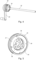
- the Fig.3 and 4 show the internal structure of the feed spindle unit 16 from Fig. 2 .
- the threaded spindle drive 17 can be seen.
- This comprises a spindle 32 extending along the longitudinal axis L, which is rotatably received in the stator tube 28.
- the spindle 32 is mounted in a spindle bearing sleeve 34.
- the spindle 32 is a trapezoidal spindle with a diameter of 12 mm and a pitch of 3 mm.
- the spindle 32 therefore has an external thread which is self-locking under most operating conditions.
- the threaded spindle drive 17 also has a spindle nut 31 sitting on the spindle 32 with an internal thread which engages with the external thread of the spindle.
- the carriage 22 can be moved along the longitudinal axis L by a relative rotation between the spindle 32 and the spindle nut 31.
- the spindle 32 is arranged in a stationary and rotatable manner in the stator tube 28 and the spindle nut 31 is connected to the carriage 22 in a rotationally fixed and axially displaceable manner.
- the spindle 32 is rotated so that the spindle nut 31 moves linearly on the spindle 32.
- the pull spindle unit 16 has an additional locking device 40 for locking the relative rotation between the spindle 32 and the spindle nut 31 when a tensile force is exerted on the connection end 13 along the longitudinal axis L.
- This locking device 40 has a friction pair 41, 42, wherein the friction pair consists of a first contact surface 41 located on the housing, namely on the spindle bearing sleeve 34, and a second contact surface 42 located on the threaded spindle drive 17 and opposite the first contact surface.
- the second contact surface 42 is supported on the first contact surface 41 in such a way that a frictional resistance exists which prevents an automatic relative rotation between the spindle 32 and the spindle nut 31 as a result of the tensile force.
- This frictional resistance increases in proportion to the applied axial load. From the Fig.3 It can be seen that the first and second contact surfaces 41, 42 extend essentially perpendicular to the longitudinal axis L. The surfaces of the contact surfaces are dimensioned such that the self-locking is achieved with sufficient safety.
- a planetary gear 30 is arranged between the latter and the spindle 32, which translates the hand crank revolution into speed so that the spindle 32 performs, for example, approximately 3.5 revolutions with one hand crank revolution and thus the required adjustment path of the slide 22 is achieved per hand crank revolution.
- a planetary gear 30 is shown in Fig.5 shown.
- a ring gear 36 is screwed in place in the stator tube 28, and a planet carrier 37 is connected to the hand crank 20.
- the planet carrier 37 drives three planet gears 38, which in turn drive a (in Fig.3 shown) which is connected to the spindle 32.
- the axis of rotation of the planet carrier 37, and thus the axis of rotation of the hand crank 20, coincides with the axis of rotation of the sun gear, and thus the axis of rotation of the spindle 32.
- Fig.6 shows the bearing of the spindle 32 in the spindle bearing sleeve 34.
- the spindle bearing sleeve 34 is firmly attached to the stator tube 28 or to another part of the housing of the feed spindle unit 16.
- the pull spindle unit described above enables good operating ergonomics, since on the one hand a user can achieve a relatively large adjustment range with relatively few turns of the hand crank, and on the other hand a self-locking of the pull spindle can be ensured even at high tensile forces.
- the adjustment range per hand crank revolution which is appropriate for operation, is achieved by using the high-speed gear.
- the additional locking device is also provided, it is no longer necessary to ensure that the spindle of the threaded spindle drive is always self-locking. This means that spindles with a larger pitch can be used.
- a larger spindle pitch has the advantage that the gear that increases speed can have a smaller gear ratio to achieve the appropriately large adjustment range. This means that a compact and simply constructed gear can be used.
Landscapes
- Health & Medical Sciences (AREA)
- Engineering & Computer Science (AREA)
- Life Sciences & Earth Sciences (AREA)
- Biomedical Technology (AREA)
- Animal Behavior & Ethology (AREA)
- General Health & Medical Sciences (AREA)
- Public Health (AREA)
- Veterinary Medicine (AREA)
- Orthopedic Medicine & Surgery (AREA)
- Surgery (AREA)
- Heart & Thoracic Surgery (AREA)
- General Engineering & Computer Science (AREA)
- Molecular Biology (AREA)
- Nuclear Medicine, Radiotherapy & Molecular Imaging (AREA)
- Medical Informatics (AREA)
- Mechanical Engineering (AREA)
- Neurosurgery (AREA)
- Oral & Maxillofacial Surgery (AREA)
- Pathology (AREA)
- Nursing (AREA)
- Vascular Medicine (AREA)
- Transmission Devices (AREA)
- Accommodation For Nursing Or Treatment Tables (AREA)
Claims (11)
- Appareil à tige de traction (16) autobloquant, destiné à être utilisé lors d'interventions chirurgicales, pourvu d'une extension allongée définissant un axe longitudinal (L), l'appareil à tige de traction comprenant :- une extrémité de service (11) pour faire fonctionner l'appareil à tige de traction ;- une extrémité de raccord (13) pour raccorder un accessoire chirurgical à l'appareil à tige de traction ;- un entraînement à tige filetée (17) présentanta) une tige (32) s'étendant le long de l'axe longitudinal (L) et pourvue d'un filetage externe ; etb) un écrou de tige (31) placé sur la tige (32), pourvu d'un filetage interne, qui est en prise avec le filetage externe ;- un coulisseau (22) pouvant être déplacé le long de l'axe longitudinal par une rotation relative entre la tige et l'écrou de tige ;- un dispositif d'entraînement (20) se trouvant à l'extrémité de service (11) pour l'entraînement en rotation de l'entraînement à tige filetée ;caractérisé en ce que
l'appareil à tige de traction (16) comprend en outre un mécanisme (30) qui est monté entre le dispositif d'entraînement (20) et l'entraînement à tige filetée (17), dans lequel le mécanisme est configuré pour transmettre un mouvement de rotation du dispositif d'entraînement (20) transformé en rapidité à l'entraînement à tige filetée (17), dans lequel l'appareil à tige de traction (16) peut être déplacé rapidement par le mécanisme (30), qui se transforme en rapidité. - Appareil à tige de traction (16) selon la revendication 1, pourvu en outre d'un dispositif d'arrêt (40) pour empêcher la rotation relative entre la tige et l'écrou de tige, lorsqu'une force de traction est appliquée à l'extrémité de raccord (13) le long de l'axe longitudinal.
- Appareil à tige de traction (16) selon la revendication 2, comprenant en outre un boîtier recevant l'entraînement à tige filetée, dans lequel le dispositif d'arrêt présente une paire de frottement, dans lequel la paire de frottement (41, 42) est constituée d'une première surface de contact (41) se trouvant sur le boîtier et d'une seconde surface de contact (42) opposée à la première surface de contact, se trouvant sur l'entraînement à tige filetée, dans lequel lorsqu'une force de traction est appliquée à l'extrémité de raccord (13) le long de l'axe longitudinal (L), la seconde surface de contact s'appuie sur la première surface de contact de sorte qu'une résistance de frottement est générée, ce qui empêche une rotation relative automatique entre la tige (32) et l'écrou de tige (31) en raison de la force de traction.
- Appareil à tige de traction (16) selon la revendication 3, dans lequel les première et seconde surfaces de contact s'étendent sensiblement perpendiculairement à l'axe longitudinal.
- Appareil à tige de traction (16) selon la revendication 3 ou 4, dans lequel la tige est disposée de manière fixe et rotative dans le boîtier et l'écrou de tige est relié au coulisseau de manière fixe en rotation, et dans lequel la seconde surface de contact est disposée sur la tige.
- Appareil à tige de traction (16) selon la revendication 5, dans lequel le boîtier comprend un manchon de palier de tige (34) sur lequel la première surface de contact est formée, et dans lequel la tige (32) présente un disque de contact (42) qui lui est relié de manière fixe en rotation et sur lequel est formée la seconde surface de contact.
- Appareil à tige de traction (16) selon l'une des revendications 1 à 6, dans lequel le mécanisme (30) comprend un engrenage planétaire.
- Appareil à tige de traction (16) selon l'une des revendications 1 à 7, dans lequel le mécanisme (30) est adapté de sorte qu'un tour du dispositif d'entraînement (20) correspond à au moins deux tours de l'entraînement à tige filetée, de préférence de sorte qu'un tour du dispositif d'entraînement (20) correspond à 3,5 tours de l'entraînement à tige filetée.
- Appareil à tige de traction (16) selon l'une des revendications 1 à 8, dans lequel un diamètre de la tige (32) est inférieur à 20 mm, en particulier inférieur à 15 mm.
- Appareil à tige de traction (16) selon la revendication 9, dans lequel un diamètre de la tige (32) est de 12 mm et le pas de la tige est de 3 mm.
- Barre d'extension (10) pour table d'opération (1), comprenant :- une barre (12), qui peut être fixée à la table d'opération (1) ;- une entretoise pouvant être déplacée (14), qui peut être déplacée le long d'un axe longitudinal de la barre (12) et qui porte un support (18) pour le pied d'un patient ;caractérisée en ce que
la barre d'extension (10) pour la table d'opération (1) comprend en outre un appareil à tige de traction (16) selon l'une des revendications 1 à 10, pour régler le support (18) pour le pied du patient par rapport à une position de l'entretoise (14) dans une direction sensiblement parallèle à un axe longitudinal (L) de l'appareil à tige de traction (16).
Applications Claiming Priority (2)
| Application Number | Priority Date | Filing Date | Title |
|---|---|---|---|
| DE102017117767.1A DE102017117767A1 (de) | 2017-08-04 | 2017-08-04 | Schnell verstellbares kompaktes Zugspindelaggregat mit Selbsthemmung zum Einsatz bei chirurgischen Eingriffen |
| PCT/EP2018/071067 WO2019025570A1 (fr) | 2017-08-04 | 2018-08-02 | Appareil à tige de traction, compact, réglable rapidement, autobloquant, destiné à être utilisé lors d'interventions chirurgicales |
Publications (2)
| Publication Number | Publication Date |
|---|---|
| EP3661472A1 EP3661472A1 (fr) | 2020-06-10 |
| EP3661472B1 true EP3661472B1 (fr) | 2024-09-25 |
Family
ID=63442595
Family Applications (1)
| Application Number | Title | Priority Date | Filing Date |
|---|---|---|---|
| EP18762228.7A Active EP3661472B1 (fr) | 2017-08-04 | 2018-08-02 | Appareil à tige de traction, compact, réglable rapidement, autobloquant, destiné à être utilisé lors d'interventions chirurgicales |
Country Status (7)
| Country | Link |
|---|---|
| US (1) | US12357524B2 (fr) |
| EP (1) | EP3661472B1 (fr) |
| JP (1) | JP2020530792A (fr) |
| KR (1) | KR20200037831A (fr) |
| CN (1) | CN110944615A (fr) |
| DE (1) | DE102017117767A1 (fr) |
| WO (1) | WO2019025570A1 (fr) |
Families Citing this family (2)
| Publication number | Priority date | Publication date | Assignee | Title |
|---|---|---|---|---|
| CN111714267A (zh) * | 2020-07-10 | 2020-09-29 | 李洪彬 | 一种可拆卸术中侧卧位下肢牵引复位器 |
| CN112914938A (zh) * | 2021-02-25 | 2021-06-08 | 乔玲 | 一种麻醉患者恢复期护理肢体固定支架 |
Citations (2)
| Publication number | Priority date | Publication date | Assignee | Title |
|---|---|---|---|---|
| US20100282009A1 (en) * | 2008-01-12 | 2010-11-11 | Martin Kahr Knudsen | Linear actuator |
| DE102013202700A1 (de) * | 2012-03-12 | 2013-09-12 | Schaeffler Technologies AG & Co. KG | Planetenwälzgetriebe und Hydrostataktor mit diesem |
Family Cites Families (14)
| Publication number | Priority date | Publication date | Assignee | Title |
|---|---|---|---|---|
| US4342309A (en) * | 1981-01-08 | 1982-08-03 | Eftekhar Nas S | Bow type traction device having corporeal insertion means |
| US4747319A (en) * | 1985-12-16 | 1988-05-31 | Jidosha Kiki Co., Ltd. | Actuator |
| FR2596637B1 (fr) * | 1986-04-03 | 1988-07-15 | Marzet Aubry | Dispositif de traction pour tables d'operations et appareillages de chirurgie orthopedique |
| CN2647507Y (zh) | 2003-09-26 | 2004-10-13 | 孙希源 | 行星齿轮传动快速装置 |
| US9119610B2 (en) * | 2005-08-10 | 2015-09-01 | Joel M. Matta | Medical table having controlled movement and method of use |
| DE102006033981B4 (de) * | 2006-07-22 | 2009-02-19 | Stabilus Gmbh | Von einem Antrieb antreibbarer Spindelantrieb für ein bewegbares Bauteil |
| WO2009062545A1 (fr) * | 2007-11-13 | 2009-05-22 | Schaerer Mayfield Medical Ag | Dispositif modulaire pour le positionnement et l'immobilisation du corps d'un patient pour des opérations chirurgicales et table d'opération correspondante |
| ES2395222T3 (es) * | 2008-01-12 | 2013-02-11 | Linak A/S | Dispositivo de accionamiento lineal |
| US8256047B2 (en) * | 2008-04-03 | 2012-09-04 | Klemm Kurt W | Combination treatment device and an anterior support device |
| DE202008014021U1 (de) | 2008-10-21 | 2009-02-12 | Condor Gmbh Medicaltechnik | Zug- und Drehtisch, insbesondere für die Hüft-Endoprothetik und Unfallchirurgie |
| DE202011106149U1 (de) * | 2011-09-28 | 2013-01-09 | Brose Fahrzeugteile Gmbh & Co. Kg, Hallstadt | Spindelantrieb zur motorischen Verstellung eines Verstellelements eines Kraftfahrzeugs |
| US8683631B2 (en) * | 2012-01-26 | 2014-04-01 | American Sterilizer Company | Sacral pad for a medical table |
| DE102014108745A1 (de) * | 2014-06-23 | 2015-12-24 | MAQUET GmbH | Vorrichtung zum selbsthemmenden bidirektionalen Antrieb einer medizinischen Behandlungsvorrichtung |
| US12036144B2 (en) * | 2015-05-31 | 2024-07-16 | Christopher James Brown | Surgical limb positioning and support device and method |
-
2017
- 2017-08-04 DE DE102017117767.1A patent/DE102017117767A1/de not_active Withdrawn
-
2018
- 2018-08-02 WO PCT/EP2018/071067 patent/WO2019025570A1/fr not_active Ceased
- 2018-08-02 KR KR1020207006030A patent/KR20200037831A/ko not_active Withdrawn
- 2018-08-02 US US16/634,747 patent/US12357524B2/en active Active
- 2018-08-02 EP EP18762228.7A patent/EP3661472B1/fr active Active
- 2018-08-02 CN CN201880048723.5A patent/CN110944615A/zh active Pending
- 2018-08-02 JP JP2020506189A patent/JP2020530792A/ja active Pending
Patent Citations (2)
| Publication number | Priority date | Publication date | Assignee | Title |
|---|---|---|---|---|
| US20100282009A1 (en) * | 2008-01-12 | 2010-11-11 | Martin Kahr Knudsen | Linear actuator |
| DE102013202700A1 (de) * | 2012-03-12 | 2013-09-12 | Schaeffler Technologies AG & Co. KG | Planetenwälzgetriebe und Hydrostataktor mit diesem |
Also Published As
| Publication number | Publication date |
|---|---|
| KR20200037831A (ko) | 2020-04-09 |
| US20200206056A1 (en) | 2020-07-02 |
| JP2020530792A (ja) | 2020-10-29 |
| CN110944615A (zh) | 2020-03-31 |
| WO2019025570A1 (fr) | 2019-02-07 |
| US12357524B2 (en) | 2025-07-15 |
| DE102017117767A1 (de) | 2019-02-07 |
| EP3661472A1 (fr) | 2020-06-10 |
Similar Documents
| Publication | Publication Date | Title |
|---|---|---|
| EP2504197B1 (fr) | Dispositif de réglage | |
| DE102004020982A1 (de) | Kraftgetriebenes Handwerkzeug mit Spanneinrichtung für ein Werkzeug | |
| EP1100183A2 (fr) | Dispositif d'actionnement à moteur électrique | |
| EP3577010B1 (fr) | Colonne de direction à positionnement motorisé pour véhicule automobile | |
| EP2146114A2 (fr) | Entraînement à double broche télescopique | |
| EP0706769A2 (fr) | Dispositif de réglage de la hauteur d'un plan de travail d'une table ou analogue | |
| DE3727975C2 (de) | Spielfreier Antrieb für den Zustellmechanismus eines Mikrotoms | |
| EP3472492B1 (fr) | Transmission à train épicycloïdal | |
| EP2949305A1 (fr) | Dispositif de réglage pour un rangement réglable en hauteur et procédé de modification d'une hauteur d'un rangement | |
| EP2194018A2 (fr) | Dispositif de levage | |
| DE102014114779B3 (de) | Spannpatrone zur Ankopplung eines Werkzeugadapters an eine Motorspindel einer Werkzeugmaschine | |
| EP3661472B1 (fr) | Appareil à tige de traction, compact, réglable rapidement, autobloquant, destiné à être utilisé lors d'interventions chirurgicales | |
| EP1637775A1 (fr) | Actionneur linéaire avec commande manuelle en cas d'urgence | |
| DE202019102490U1 (de) | Adapterplatte und Schnellklemmvorrichtung sowie damit versehene Anordnung bzw. Laborschwingmühle | |
| EP2886223A1 (fr) | Tête à rouler les filets | |
| EP3323571B1 (fr) | Appareil de sciage pour une scie circulaire | |
| DE102009024061B4 (de) | Maschinenreibahle | |
| EP1152167B1 (fr) | Dispositif pour règler la position entre pièces mobiles l'une par rapport à l'autre | |
| DE102013221349A1 (de) | Antriebseinheit | |
| DE102004056574B4 (de) | Arretiervorrichtung für ein verstellbares Anschlussteil | |
| DE102024106302B3 (de) | Verstellantrieb für eine Lenksäule eines Kraftfahrzeugs und Lenksäule für ein Kraftfahrzeug | |
| WO2005035331A1 (fr) | Systeme de colonne de direction compressible par coulissage | |
| DE2837492A1 (de) | Feststellbremse fuer zeichenanlagen | |
| DE102005022711B3 (de) | Spannhülse zur Befestigung auf einer zylindrischen Welle oder Achse | |
| DE102016000094A1 (de) | Einspannvorrichtung zum Verspannen eines Werkstücks |
Legal Events
| Date | Code | Title | Description |
|---|---|---|---|
| STAA | Information on the status of an ep patent application or granted ep patent |
Free format text: STATUS: UNKNOWN |
|
| STAA | Information on the status of an ep patent application or granted ep patent |
Free format text: STATUS: THE INTERNATIONAL PUBLICATION HAS BEEN MADE |
|
| PUAI | Public reference made under article 153(3) epc to a published international application that has entered the european phase |
Free format text: ORIGINAL CODE: 0009012 |
|
| STAA | Information on the status of an ep patent application or granted ep patent |
Free format text: STATUS: REQUEST FOR EXAMINATION WAS MADE |
|
| 17P | Request for examination filed |
Effective date: 20200225 |
|
| AK | Designated contracting states |
Kind code of ref document: A1 Designated state(s): AL AT BE BG CH CY CZ DE DK EE ES FI FR GB GR HR HU IE IS IT LI LT LU LV MC MK MT NL NO PL PT RO RS SE SI SK SM TR |
|
| AX | Request for extension of the european patent |
Extension state: BA ME |
|
| DAV | Request for validation of the european patent (deleted) | ||
| DAX | Request for extension of the european patent (deleted) | ||
| STAA | Information on the status of an ep patent application or granted ep patent |
Free format text: STATUS: EXAMINATION IS IN PROGRESS |
|
| 17Q | First examination report despatched |
Effective date: 20221005 |
|
| GRAP | Despatch of communication of intention to grant a patent |
Free format text: ORIGINAL CODE: EPIDOSNIGR1 |
|
| STAA | Information on the status of an ep patent application or granted ep patent |
Free format text: STATUS: GRANT OF PATENT IS INTENDED |
|
| RIC1 | Information provided on ipc code assigned before grant |
Ipc: A61B 90/14 20160101ALN20240306BHEP Ipc: A61F 5/042 20060101ALN20240306BHEP Ipc: A61G 13/00 20060101ALI20240306BHEP Ipc: A61G 13/12 20060101AFI20240306BHEP |
|
| INTG | Intention to grant announced |
Effective date: 20240320 |
|
| GRAS | Grant fee paid |
Free format text: ORIGINAL CODE: EPIDOSNIGR3 |
|
| P01 | Opt-out of the competence of the unified patent court (upc) registered |
Free format text: CASE NUMBER: APP_38189/2024 Effective date: 20240627 |
|
| GRAA | (expected) grant |
Free format text: ORIGINAL CODE: 0009210 |
|
| STAA | Information on the status of an ep patent application or granted ep patent |
Free format text: STATUS: THE PATENT HAS BEEN GRANTED |
|
| AK | Designated contracting states |
Kind code of ref document: B1 Designated state(s): AL AT BE BG CH CY CZ DE DK EE ES FI FR GB GR HR HU IE IS IT LI LT LU LV MC MK MT NL NO PL PT RO RS SE SI SK SM TR |
|
| REG | Reference to a national code |
Ref country code: GB Ref legal event code: FG4D Free format text: NOT ENGLISH |
|
| REG | Reference to a national code |
Ref country code: CH Ref legal event code: EP |
|
| REG | Reference to a national code |
Ref country code: DE Ref legal event code: R096 Ref document number: 502018015173 Country of ref document: DE |
|
| REG | Reference to a national code |
Ref country code: IE Ref legal event code: FG4D Free format text: LANGUAGE OF EP DOCUMENT: GERMAN |
|
| REG | Reference to a national code |
Ref country code: LT Ref legal event code: MG9D |
|
| PG25 | Lapsed in a contracting state [announced via postgrant information from national office to epo] |
Ref country code: NO Free format text: LAPSE BECAUSE OF FAILURE TO SUBMIT A TRANSLATION OF THE DESCRIPTION OR TO PAY THE FEE WITHIN THE PRESCRIBED TIME-LIMIT Effective date: 20241225 |
|
| PG25 | Lapsed in a contracting state [announced via postgrant information from national office to epo] |
Ref country code: GR Free format text: LAPSE BECAUSE OF FAILURE TO SUBMIT A TRANSLATION OF THE DESCRIPTION OR TO PAY THE FEE WITHIN THE PRESCRIBED TIME-LIMIT Effective date: 20241226 Ref country code: FI Free format text: LAPSE BECAUSE OF FAILURE TO SUBMIT A TRANSLATION OF THE DESCRIPTION OR TO PAY THE FEE WITHIN THE PRESCRIBED TIME-LIMIT Effective date: 20240925 |
|
| PG25 | Lapsed in a contracting state [announced via postgrant information from national office to epo] |
Ref country code: BG Free format text: LAPSE BECAUSE OF FAILURE TO SUBMIT A TRANSLATION OF THE DESCRIPTION OR TO PAY THE FEE WITHIN THE PRESCRIBED TIME-LIMIT Effective date: 20240925 |
|
| PG25 | Lapsed in a contracting state [announced via postgrant information from national office to epo] |
Ref country code: LV Free format text: LAPSE BECAUSE OF FAILURE TO SUBMIT A TRANSLATION OF THE DESCRIPTION OR TO PAY THE FEE WITHIN THE PRESCRIBED TIME-LIMIT Effective date: 20240925 |
|
| PG25 | Lapsed in a contracting state [announced via postgrant information from national office to epo] |
Ref country code: RS Free format text: LAPSE BECAUSE OF FAILURE TO SUBMIT A TRANSLATION OF THE DESCRIPTION OR TO PAY THE FEE WITHIN THE PRESCRIBED TIME-LIMIT Effective date: 20241225 |
|
| REG | Reference to a national code |
Ref country code: NL Ref legal event code: MP Effective date: 20240925 |
|
| PG25 | Lapsed in a contracting state [announced via postgrant information from national office to epo] |
Ref country code: RS Free format text: LAPSE BECAUSE OF FAILURE TO SUBMIT A TRANSLATION OF THE DESCRIPTION OR TO PAY THE FEE WITHIN THE PRESCRIBED TIME-LIMIT Effective date: 20241225 Ref country code: NO Free format text: LAPSE BECAUSE OF FAILURE TO SUBMIT A TRANSLATION OF THE DESCRIPTION OR TO PAY THE FEE WITHIN THE PRESCRIBED TIME-LIMIT Effective date: 20241225 Ref country code: LV Free format text: LAPSE BECAUSE OF FAILURE TO SUBMIT A TRANSLATION OF THE DESCRIPTION OR TO PAY THE FEE WITHIN THE PRESCRIBED TIME-LIMIT Effective date: 20240925 Ref country code: GR Free format text: LAPSE BECAUSE OF FAILURE TO SUBMIT A TRANSLATION OF THE DESCRIPTION OR TO PAY THE FEE WITHIN THE PRESCRIBED TIME-LIMIT Effective date: 20241226 Ref country code: FI Free format text: LAPSE BECAUSE OF FAILURE TO SUBMIT A TRANSLATION OF THE DESCRIPTION OR TO PAY THE FEE WITHIN THE PRESCRIBED TIME-LIMIT Effective date: 20240925 Ref country code: BG Free format text: LAPSE BECAUSE OF FAILURE TO SUBMIT A TRANSLATION OF THE DESCRIPTION OR TO PAY THE FEE WITHIN THE PRESCRIBED TIME-LIMIT Effective date: 20240925 |
|
| PG25 | Lapsed in a contracting state [announced via postgrant information from national office to epo] |
Ref country code: NL Free format text: LAPSE BECAUSE OF FAILURE TO SUBMIT A TRANSLATION OF THE DESCRIPTION OR TO PAY THE FEE WITHIN THE PRESCRIBED TIME-LIMIT Effective date: 20240925 |
|
| PG25 | Lapsed in a contracting state [announced via postgrant information from national office to epo] |
Ref country code: PT Free format text: LAPSE BECAUSE OF FAILURE TO SUBMIT A TRANSLATION OF THE DESCRIPTION OR TO PAY THE FEE WITHIN THE PRESCRIBED TIME-LIMIT Effective date: 20250127 Ref country code: IS Free format text: LAPSE BECAUSE OF FAILURE TO SUBMIT A TRANSLATION OF THE DESCRIPTION OR TO PAY THE FEE WITHIN THE PRESCRIBED TIME-LIMIT Effective date: 20250125 |
|
| PG25 | Lapsed in a contracting state [announced via postgrant information from national office to epo] |
Ref country code: RO Free format text: LAPSE BECAUSE OF FAILURE TO SUBMIT A TRANSLATION OF THE DESCRIPTION OR TO PAY THE FEE WITHIN THE PRESCRIBED TIME-LIMIT Effective date: 20240925 Ref country code: SM Free format text: LAPSE BECAUSE OF FAILURE TO SUBMIT A TRANSLATION OF THE DESCRIPTION OR TO PAY THE FEE WITHIN THE PRESCRIBED TIME-LIMIT Effective date: 20240925 |
|
| PG25 | Lapsed in a contracting state [announced via postgrant information from national office to epo] |
Ref country code: ES Free format text: LAPSE BECAUSE OF FAILURE TO SUBMIT A TRANSLATION OF THE DESCRIPTION OR TO PAY THE FEE WITHIN THE PRESCRIBED TIME-LIMIT Effective date: 20240925 |
|
| PG25 | Lapsed in a contracting state [announced via postgrant information from national office to epo] |
Ref country code: EE Free format text: LAPSE BECAUSE OF FAILURE TO SUBMIT A TRANSLATION OF THE DESCRIPTION OR TO PAY THE FEE WITHIN THE PRESCRIBED TIME-LIMIT Effective date: 20240925 |
|
| PG25 | Lapsed in a contracting state [announced via postgrant information from national office to epo] |
Ref country code: CZ Free format text: LAPSE BECAUSE OF FAILURE TO SUBMIT A TRANSLATION OF THE DESCRIPTION OR TO PAY THE FEE WITHIN THE PRESCRIBED TIME-LIMIT Effective date: 20240925 Ref country code: PL Free format text: LAPSE BECAUSE OF FAILURE TO SUBMIT A TRANSLATION OF THE DESCRIPTION OR TO PAY THE FEE WITHIN THE PRESCRIBED TIME-LIMIT Effective date: 20240925 |
|
| PG25 | Lapsed in a contracting state [announced via postgrant information from national office to epo] |
Ref country code: SK Free format text: LAPSE BECAUSE OF FAILURE TO SUBMIT A TRANSLATION OF THE DESCRIPTION OR TO PAY THE FEE WITHIN THE PRESCRIBED TIME-LIMIT Effective date: 20240925 |
|
| REG | Reference to a national code |
Ref country code: DE Ref legal event code: R097 Ref document number: 502018015173 Country of ref document: DE |
|
| PG25 | Lapsed in a contracting state [announced via postgrant information from national office to epo] |
Ref country code: DK Free format text: LAPSE BECAUSE OF FAILURE TO SUBMIT A TRANSLATION OF THE DESCRIPTION OR TO PAY THE FEE WITHIN THE PRESCRIBED TIME-LIMIT Effective date: 20240925 |
|
| PLBE | No opposition filed within time limit |
Free format text: ORIGINAL CODE: 0009261 |
|
| STAA | Information on the status of an ep patent application or granted ep patent |
Free format text: STATUS: NO OPPOSITION FILED WITHIN TIME LIMIT |
|
| 26N | No opposition filed |
Effective date: 20250626 |
|
| PG25 | Lapsed in a contracting state [announced via postgrant information from national office to epo] |
Ref country code: SE Free format text: LAPSE BECAUSE OF FAILURE TO SUBMIT A TRANSLATION OF THE DESCRIPTION OR TO PAY THE FEE WITHIN THE PRESCRIBED TIME-LIMIT Effective date: 20240925 |
|
| PGFP | Annual fee paid to national office [announced via postgrant information from national office to epo] |
Ref country code: DE Payment date: 20250724 Year of fee payment: 8 |
|
| PGFP | Annual fee paid to national office [announced via postgrant information from national office to epo] |
Ref country code: IT Payment date: 20250723 Year of fee payment: 8 |
|
| PGFP | Annual fee paid to national office [announced via postgrant information from national office to epo] |
Ref country code: GB Payment date: 20250725 Year of fee payment: 8 |
|
| PGFP | Annual fee paid to national office [announced via postgrant information from national office to epo] |
Ref country code: FR Payment date: 20250723 Year of fee payment: 8 |
|
| PG25 | Lapsed in a contracting state [announced via postgrant information from national office to epo] |
Ref country code: HR Free format text: LAPSE BECAUSE OF FAILURE TO SUBMIT A TRANSLATION OF THE DESCRIPTION OR TO PAY THE FEE WITHIN THE PRESCRIBED TIME-LIMIT Effective date: 20240925 |
|
| REG | Reference to a national code |
Ref country code: CH Ref legal event code: H13 Free format text: ST27 STATUS EVENT CODE: U-0-0-H10-H13 (AS PROVIDED BY THE NATIONAL OFFICE) Effective date: 20260324 |
|
| PG25 | Lapsed in a contracting state [announced via postgrant information from national office to epo] |
Ref country code: MC Free format text: LAPSE BECAUSE OF FAILURE TO SUBMIT A TRANSLATION OF THE DESCRIPTION OR TO PAY THE FEE WITHIN THE PRESCRIBED TIME-LIMIT Effective date: 20240925 |
|
| PG25 | Lapsed in a contracting state [announced via postgrant information from national office to epo] |
Ref country code: LU Free format text: LAPSE BECAUSE OF NON-PAYMENT OF DUE FEES Effective date: 20250802 |
|
| PG25 | Lapsed in a contracting state [announced via postgrant information from national office to epo] |
Ref country code: CH Free format text: LAPSE BECAUSE OF NON-PAYMENT OF DUE FEES Effective date: 20250831 |