EP3665356B1 - Joint de colonne montante universel pour forage sous pression et forage de remontée de boue sous-marine gérés - Google Patents
Joint de colonne montante universel pour forage sous pression et forage de remontée de boue sous-marine gérés Download PDFInfo
- Publication number
- EP3665356B1 EP3665356B1 EP18844975.5A EP18844975A EP3665356B1 EP 3665356 B1 EP3665356 B1 EP 3665356B1 EP 18844975 A EP18844975 A EP 18844975A EP 3665356 B1 EP3665356 B1 EP 3665356B1
- Authority
- EP
- European Patent Office
- Prior art keywords
- flow
- tube
- pump
- outlet
- mud
- Prior art date
- Legal status (The legal status is an assumption and is not a legal conclusion. Google has not performed a legal analysis and makes no representation as to the accuracy of the status listed.)
- Active
Links
Images


Classifications
-
- E—FIXED CONSTRUCTIONS
- E21—EARTH OR ROCK DRILLING; MINING
- E21B—EARTH OR ROCK DRILLING; OBTAINING OIL, GAS, WATER, SOLUBLE OR MELTABLE MATERIALS OR A SLURRY OF MINERALS FROM WELLS
- E21B21/00—Methods or apparatus for flushing boreholes, e.g. by use of exhaust air from motor
- E21B21/08—Controlling or monitoring pressure or flow of drilling fluid, e.g. automatic filling of boreholes, automatic control of bottom pressure
-
- E—FIXED CONSTRUCTIONS
- E21—EARTH OR ROCK DRILLING; MINING
- E21B—EARTH OR ROCK DRILLING; OBTAINING OIL, GAS, WATER, SOLUBLE OR MELTABLE MATERIALS OR A SLURRY OF MINERALS FROM WELLS
- E21B17/00—Drilling rods or pipes; Flexible drill strings; Kellies; Drill collars; Sucker rods; Cables; Casings; Tubings
- E21B17/01—Risers
-
- E—FIXED CONSTRUCTIONS
- E21—EARTH OR ROCK DRILLING; MINING
- E21B—EARTH OR ROCK DRILLING; OBTAINING OIL, GAS, WATER, SOLUBLE OR MELTABLE MATERIALS OR A SLURRY OF MINERALS FROM WELLS
- E21B21/00—Methods or apparatus for flushing boreholes, e.g. by use of exhaust air from motor
- E21B21/001—Methods or apparatus for flushing boreholes, e.g. by use of exhaust air from motor specially adapted for underwater drilling
-
- E—FIXED CONSTRUCTIONS
- E21—EARTH OR ROCK DRILLING; MINING
- E21B—EARTH OR ROCK DRILLING; OBTAINING OIL, GAS, WATER, SOLUBLE OR MELTABLE MATERIALS OR A SLURRY OF MINERALS FROM WELLS
- E21B21/00—Methods or apparatus for flushing boreholes, e.g. by use of exhaust air from motor
- E21B21/10—Valve arrangements in drilling-fluid circulation systems
- E21B21/106—Valve arrangements outside the borehole, e.g. kelly valves
Definitions
- This disclosure relates to the field of wellbore drilling. More specifically, the disclosure relates to marine drilling through a conduit ("riser") extending from a subsea wellhead proximate the bottom of a body of water to a drilling unit on the water surface.
- a conduit extending from a subsea wellhead proximate the bottom of a body of water to a drilling unit on the water surface.
- Marine wellbore drilling includes locating a drilling unit on a platform at the surface of a body of water.
- a surface casing may extend from proximate the water bottom to a selected depth into the formations below the water bottom.
- a valve system (“wellhead”) may be coupled to the top of the surface casing proximate the water bottom.
- a conduit called a “riser” may be coupled to the top of the wellhead, e.g., through a lower marine riser package (“LMRP”) and may extend to the drilling unit on the water surface.
- LMRP lower marine riser package
- a drill string may be extended from the drilling unit, through the riser, LMRP, wellhead and surface casing and into the formations below the bottom of the surface casing in order to extend the length of the wellbore.
- Drilling fluid may be pumped through the drill string by pumps located on the drilling unit.
- the mud is discharged through the bottom of the drill string from a drill bit coupled to the bottom of the drill string.
- the mud moves upwardly through an annular space (“annulus”) between the drill string and the wall of the drilled wellbore, and subsequently the surface casing, wellhead, LMRP and riser ultimately to be returned to the drilling unit on the water surface.
- Some drilling procedures include changing the fluid pressure exerted by the column of mud in the annulus.
- Such drilling procedures include "managed pressure drilling” (MPD) wherein a sealing element, called a rotating control device (“RCD”) is disposed at a selected longitudinal position in the annulus and a fluid outlet is provided below the RCD such that returning mud from the annulus may have its flow rate and/or pressure controlled, for example, using an adjustable orifice choke or other flow control device.
- MPD may enable using different density (“weight”) mud than would otherwise be required in order to provide sufficient hydrostatic pressure to keep fluid in exposed formations in the wellbore from entering the wellbore.
- An example method for MPD is described in U.S. Patents Nos. 6,904,981 issued to van Riet , 7,185,719 issued to van Riet , and 7,350,597 issued to Reitsma .
- SMD drilling Other drilling procedures (referred to as subsea mudlift drilling or “SMD drilling”) may provide lower pressure in the annulus than would otherwise exist as a result of the hydrostatic pressure of the mud in the annulus.
- the lower pressure may be provided by using a pump (“SMD pump”) disposed at a selected elevation below the water surface, having its suction side in fluid communication with the annulus and its discharge connected to a mud return line extending to the drilling unit on the water surface.
- SMD pump disposed at a selected elevation below the water surface, having its suction side in fluid communication with the annulus and its discharge connected to a mud return line extending to the drilling unit on the water surface.
- WO2011/058031 describes a system for well control during drilling, completion or well intervention of a subsea well, comprising a wellbore and a subsea blow-out preventer (BOP) on top of the wellbore, a separator cavity adapted to be established between a closed lower closing element and a closed upper closing element in a part of the BOP and/or in a lower marine riser package (LMRP), a bypass line having a fixed or adjustable choke extending from the wellbore to the separator cavity, the separator cavity being adapted to receive well fluid via the bypass line and a gas return line extending from an upper part of said separator cavity and a liquid return line with a lift pump extending from a lower part of the separator cavity.
- BOP subsea blow-out preventer
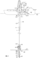
- FIG. 1 shows an example marine drilling system.
- a drilling vessel 110 floats on the surface of a body of water 113.
- a wellhead 115 is positioned on the water bottom 117.
- the wellhead 115 defines the upper surface or "mudline" of a wellbore 122 drilled through sub-bottom formations 118.
- a drill string 119 having a drill bit 120 disposed at a bottom end thereof are suspended from a derrick 121 mounted on the drilling vessel 110.
- the drill string 119 may extend from the derrick 121 to the bottom of the wellbore 122.
- a length of structural casing 127 extends from the wellhead 115 to a selected depth in the wellbore 122.
- a riser 123 may extend from the upper end of a blowout preventer stack 124 coupled to the wellhead 115, upwardly to the drilling vessel 110.
- the riser 123 may comprise flexible couplings such as ball joints 125 proximate each longitudinal end of the riser 123 to enable some movement of the drilling vessel 110 without causing damage to the riser 123.
- a riser segment 10 which will be explained in more detail with reference to FIGS. 2 , 3 and 4 , may be disposed at a selected longitudinal position along the riser 123.
- the riser segment 10 may be disposed below a housing 50 configured to receive a rotating control device (RCD) bearing and seal assembly (explained with reference to FIGS. 5 and 6).
- the riser segment 10 may comprise a mud return line 42 which will be further explained with reference to FIG. 2 .
- the mud return line 42 in some embodiments may be connected to a flowmeter 140 to measure the rate at which fluid is discharged from the riser 123, and thus from the wellbore 122.
- a drilling fluid (“mud") treatment system 132 which may comprise components (none shown separately for clarity) such as a gas separator, one or more shaker tables, and a clean mud return line 132A which returns cleaned mud to a tank or reservoir 131A.
- a pump 131 disposed on the drilling vessel 110 may lift mud from the tank 131A and discharge the lifted mud into a standpipe 131B or similar conduit.
- the standpipe 131B is in fluid communication with the interior of the drill string 119 at the upper end of the drill string 119 such that the discharged mud moves through the drill string 119 downwardly and is ultimately discharged through nozzles, jets, or courses through the drill bit 120 and thereby into the wellbore 122.
- the mud moves along the interior of the wellbore 122 upwardly into the riser 123 until it reaches the riser segment 10. Further movement of the mud beyond the riser segment 10 will be further explained with reference to FIGS. 2 through 4 .
- a pressure sensor 144 and a flowmeter 142 may be placed in fluid communication with the pump 131 discharge at any selected position between the pump 131 and the upper end of the drill string 119.
- the pressure sensor 144 may measure pressure of the mud in the standpipe 131B and the flowmeter 142 may measure rate of flow of the mud through the standpipe 131B to enable determining pressure of the mud at any longitudinal position along the wellbore 122 and/or the riser 123.
- a pressure sensor may be disposed proximate the bottom end of the drill string 119, such pressure sensor being shown at 146. Such pressure sensor may have its measurements communicated to the drilling vessel 110 using signal transmission devices known in the art.
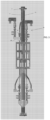
- FIG. 2 shows an example riser segment ("joint") according to various aspects of the present disclosure.
- the riser joint 10 may comprise a tube 11 having dimensions and made from materials known in the art for marine drilling risers.
- the tube 11 may comprise a connecting flange 12 at each longitudinal end of the tube 11.
- the flanges 12 may be configured in any manner known in the art for connecting riser joints longitudinally end to end.
- a flow diverter manifold 16 may be coupled to the tube 11, as shown in FIG. 2 proximate the lower end of the tube 11.
- the flow diverter manifold 16 may have at least one, and in the present embodiment may have two fluid outlets 17 each in fluid communication with the interior of the tube 11.
- Each fluid outlet 17 may have a valve 18, 19, for example a double isolated valve block, coupled at one end thereof to a respective fluid outlet 17 such that each fluid outlet 17 may be selectively opened or closed to flow from the interior of the tube 11.
- each valve 18, 19 may be coupled to respective a flow "tee" 22, whereby fluid leaving the tube 11 may be selectively provided to one or both of a flow line 24 and a SMD pump conduit 28A, 28B.
- the SMD pump conduits 28A, 28B may be selectively opened to and closed to flow to the respective flow tee 22 by respective valves 26, 27 disposed between an end of each SMD pump conduit 28A, 28B and the corresponding flow tee 22.
- each flow line 24 may be connected to the corresponding flow tee 22 using a right angle flow block 20, however, such configuration using right angle flow blocks 20 is only meant to serve as an example and is not a limit on the scope of the present disclosure.
- one of the SMD pump conduits 28A may be fluidly connected to an intake of an SMD pump (not shown in FIG. 2 ).
- the other SMD pump conduit 28B may be fluidly connected to a discharge of the SMD pump (not shown in FIG. 2 ).
- One of the flow lines 24 may be fluidly connected to a valve 34, which may be a double isolated valve block and from the valve 34 to a first "gooseneck" 38.
- the first gooseneck 38 may be connected to the valve 34 using a stab in connector 36, and may have an outlet connector 38A for coupling to, for example, a flexible fluid hose (not shown in the figures).
- the other of the flow lines 25 may be fluidly connected to a manifold 32, which in some embodiments may be a swing arm manifold 32.
- One outlet 32A of the swing arm manifold 32 may be connected to a valve 40 which may selectively open and close fluid communication between the one outlet 32A of the swing arm manifold 32 and a mud return line 42.
- valve 35 Another outlet 32B of the swing arm manifold 32 may be connected to a valve 35, which in some embodiments may be a double isolated valve block.
- the valve 35 may be in fluid communication with a second gooseneck 39 also having a connector 38A for coupling, for example, to a flexible hose (not shown in the figures).
- the second gooseneck 39 may be coupled to the valve 35 using a stab in connector 37 similar in configuration to the stab in connector 36 coupled to the first gooseneck 38.
- a frame 14 may be coupled to the tube 11 using reinforcements 14A, 14B proximate the respective upper and lower ends of the frame 14.
- the frame 14 may provide a mounting place for the previously described SMD pump (not shown in FIG. 2 ).
- the frame 14 may be permanently mounted to the tube 11 in some embodiments. In some embodiments, the frame 14 may be removably mounted to the tube 11.
- FIG. 3 Another view of the riser joint 10 is shown in FIG. 3 , wherein may be observed the mud return line 42 extending from the valve 40, which itself is coupled to the swing arm manifold 32.
- the mud return line 42 may extend through a suitable opening in the flange 12 proximate the top of the tube 11.
- Each riser joint (not shown in FIG. 3 ) coupled above the riser joint 10 and below the riser joint 10 according to the present disclosure may comprise a segment of conduit (not shown) to connect the mud return line 42 to the drilling unit on the water surface.
- FIG. 4 shows a side view of the riser joint 10 rotated 90 degrees from the view shown in FIGS. 2 and 3 , wherein may be observed an ROV stab 40A to operate the valve (40 in FIG. 2 ) to open and close fluid flow to the mud return line 42.
- ROV stabs 26A, 27A may be provided to operate the corresponding valves (26, 27 in FIG. 2 ) that open and close the SMD pump conduits (28A, 28B in FIG. 2 ) to flow.
- supports 31 for mounting the SMD pump (not shown in the figures).
- the riser joint 10 shown in FIGS. 2 , 3 and 4 may be used in several configurations for conventional drilling, SMD drilling and MPD drilling.
- valves 18, 19, 26, 27, 34, 35 and 40 may be closed.
- Riser segments coupled to the riser joint 10 above and below the riser joint may be ordinary riser joints having only a tube, and flanges at the longitudinal ends thereof.
- one of the riser segments above the riser joint 10 may comprise a housing (see 50 in FIG. 1 ) for receiving a RCD bearing and seal assembly in the event it is desired to change from conventional drilling to MPD drilling without the need to disassemble any part of the riser ( FIG. 1 ).
- the RCD bearing and seal receiver FIG. 1
- the RCD bearing and seal receiver may freely enable passage of a drill string therethrough so as not to interfere in any way with conventional drilling.
- a RCD bearing and seal assembly may be assembled to the drill string ( FIG. 1 ) and moved into the RCD bearing and seal receiver using the drill string.
- the drill string may be advanced to the bottom of the wellbore to resume drilling, among other well operations.
- valves 18, 19, 26, 27, 34, 35 and 40 are initially closed.
- the valve 19 shown on the right hand side of the flow diverter manifold 16 may be opened.
- valve 40 may be opened.
- valve 35 on the right hand side of the tube 11 in FIG. 2 may be opened.
- MPD drilling may proceed by providing a selected flow restriction from the mud return line 40 or the flexible hose (not shown) to maintain a selected mud pressure in the annulus.
- valves 18, 19, 26, 27, 34, 35 and 40 are initially closed.
- the valve 18 on the left hand side of the tube 11 may be opened.
- the valve 26 connecting valve 18 to the SMD pump conduit 28A may be opened so that fluid leaving the tube 11 through the flow diverter manifold 16 may be drawn into the SMD pump ( FIG. 1 ).
- the valve 19 on the right hand side of the tube 11 may remain closed, while the valve 27 at the lower end of the SMD pump conduit 28B may be opened. Discharge from the SMD pump ( FIG.
- valve 40 may be opened to use the mud return line as a SMD pump flow return line, or valve 39 connected to the swing arm manifold 32 may be opened if a flexible hose (not shown) is connected to the second gooseneck 39 to provide a return flow path for the mud discharged from the SMD pump ( FIG. 1 ).
- SMD drilling may not require a RCD, and the RCD bearing and seal assembly may be omitted from the drill string for SMD drilling.
Landscapes
- Engineering & Computer Science (AREA)
- Life Sciences & Earth Sciences (AREA)
- Geology (AREA)
- Mining & Mineral Resources (AREA)
- Mechanical Engineering (AREA)
- Physics & Mathematics (AREA)
- Environmental & Geological Engineering (AREA)
- Fluid Mechanics (AREA)
- General Life Sciences & Earth Sciences (AREA)
- Geochemistry & Mineralogy (AREA)
- Earth Drilling (AREA)
- Excavating Of Shafts Or Tunnels (AREA)
Claims (9)
- Appareil comprenant :un tube (11) présentant au moins une sortie d'écoulement (17) en communication avec l'intérieur du tube (11), dans lequel le tube forme un segment d'une colonne montante (123) s'étendant entre un puits de forage (122) et une unité de forage (119) à la surface d'une masse d'eau ;une pompe présentant une entrée raccordée à un premier conduit de pompe (28A) et une sortie raccordée à un second conduit de pompe (28B) ;une conduite de retour de boue (42) s'étendant depuis un collecteur (32) vers l'unité de forage (119), la pompe étant conçue pour soulever la boue vers l'unité de forage (119) à travers la conduite de retour de boue (42) ;une première pluralité de vannes (18, 19, 26) destinées à dévier de manière sélective l'écoulement à l'intérieur du tube (11) en raccordant la sortie d'écoulement (17) à une entrée de la pompe par l'intermédiaire du premier conduit de pompe (28A), dans lequel lorsque la sortie d'écoulement (17) est raccordée à l'entrée de la pompe, la pompe fonctionne pour soulever la boue vers l'unité de forage (119) de manière à maintenir une pression sélectionnée dans le puits de forage (122) ;une seconde pluralité de vannes (18, 19, 27, 40) destinées à dévier de manière sélective l'écoulement à l'intérieur du tube (11) en raccordant la sortie d'écoulement (17) à la conduite de retour de boue (42) et destinées à fermer la sortie de la pompe, dans lequel la sortie d'écoulement (17) est raccordée à une première conduite d'écoulement (25) par l'intermédiaire d'un bloc d'écoulement (20), la conduite d'écoulement (25) est raccordée au collecteur (32) et à la conduite de retour de boue (42) et la sortie d'écoulement (17) est raccordée à une sortie de la pompe par l'intermédiaire du second conduit de pompe (28B), dans lequel lorsque la sortie d'écoulement (17) est raccordée à la conduite de retour de boue (42) et que la sortie de pompe est fermée, l'écoulement dans la colonne montante (123) au-dessus du tube (11) est arrêté ;dans lequel la sortie d'écoulement (17) du tube (11) comprend un second collecteur (16) présentant deux sorties d'écoulement séparées (17), chacune en communication fluidique avec l'intérieur du tube (11) et dans lequel chacune des deux sorties d'écoulement séparées comprend une vanne (18, 19) de la première pluralité de vannes agencées pour fermer la communication fluidique entre la sortie d'écoulement respective (17) et l'intérieur du tube (11) ; etdans lequel l'appareil comprend en outre un té d'écoulement (22) raccordé à chaque vanne (18, 19) de la première pluralité de vannes agencées pour fermer la communication fluidique entre la sortie d'écoulement respective (17) et l'intérieur du tube (11), une première sortie de l'un des tés d'écoulement (22) est raccordée au premier conduit de pompe (28A) et une seconde sortie est raccordée à un seconde conduite d'écoulement (24) et une première sortie de l'autre des tés d'écoulement (22) est raccordée au second conduit de pompe (28B) et une seconde sortie est raccordée à la première conduite d'écoulement (25).
- Appareil selon la revendication 1, comprenant en outre une bride de raccordement (12) disposée à chaque extrémité longitudinale du tube (11).
- Appareil selon la revendication 1, comprenant en outre un logement (50) apte à recevoir un roulement du dispositif de commande rotatif et un ensemble d'étanchéité disposés au-dessus du tube (11).
- Appareil selon la revendication 1, comprenant en outre un cadre (14) accouplé à l'extérieur du tube (11) destiné à retenir la pompe à fluide.
- Appareil selon la revendication 1, dans lequel chacune des première et seconde conduites d'écoulement (25, 24) est raccordée à un col de cygne respectif (38, 39) par l'intermédiaire d'une vanne (34, 35) et d'un raccord à guidage (36, 37) pour fermer de manière sélective une sortie de chaque conduite d'écoulement.
- Appareil selon la revendication 5, dans lequel chaque col de cygne (38, 39) comprend un raccordement (38a) apte à être raccordé à un tuyau flexible.
- Procédé, comprenant :le retour de boue depuis un puits de forage (122) dans un tube (11) qui forme un segment de colonne montante (123) s'étendant entre le puits de forage (122) et une unité de forage (119) à la surface d'une masse d'eau ;la déviation de manière sélective de l'écoulement à l'intérieur du tube (11) vers l'une des entrées d'une pompe à fluide par l'intermédiaire d'un premier conduit de pompe (28A) et d'une conduite de retour de boue (42) s'étendant depuis le tube (11) vers à l'unité de forage (119) en raccordant une sortie d'écoulement (17) du tube (11) à une des conduites de retour de boue (42) et une entrée de la pompe par l'intermédiaire du premier conduit de pompe (28A), dans lequel lorsque la sortie d'écoulement (17) est raccordée à l'entrée de la pompe, la pompe fonctionne pour soulever la boue jusqu'à l'unité de forage (119) de manière à maintenir une pression sélectionnée dans le puits de forage (122) et dans lequel, lorsque la sortie d'écoulement (17) est raccordée à la conduite de retour de boue (42), une sortie de la pompe est fermée de manière à ce que l'écoulement dans la colonne montante (123) au-dessus du tube (11) soit arrêté.
- Procédé selon la revendication 7, dans lequel, lorsque l'écoulement est dévié de manière sélective vers la conduite de retour de boue (42), la commande d'évacuation de la boue depuis la conduite de retour de boue (42) pour maintenir une pression de boue sélectionnée dans le puits de forage (122).
- Procédé selon la revendication 7, dans lequel, lorsque la sortie d'écoulement (17) est raccordée à la conduite de retour de boue (42) et que la sortie de la pompe est fermée de manière à ce que l'écoulement dans la colonne montante (123) au-dessus du tube (11) soit arrêté, comprenant en outre l'insertion d'un train de tiges présentant un roulement du dispositif de commande rotatif et un ensemble d'étanchéité de celui-ci dans le puits de forage (122) de sorte que le roulement du dispositif de commande rotatif et l'ensemble d'étanchéité viennent en prise avec un logement (50) disposé au-dessus du tube (11).
Applications Claiming Priority (3)
| Application Number | Priority Date | Filing Date | Title |
|---|---|---|---|
| US201762544319P | 2017-08-11 | 2017-08-11 | |
| US201762560658P | 2017-09-19 | 2017-09-19 | |
| PCT/US2018/046577 WO2019033126A1 (fr) | 2017-08-11 | 2018-08-13 | Joint de colonne montante universel pour forage sous pression et forage de remontée de boue sous-marine gérés |
Publications (3)
| Publication Number | Publication Date |
|---|---|
| EP3665356A1 EP3665356A1 (fr) | 2020-06-17 |
| EP3665356A4 EP3665356A4 (fr) | 2021-03-31 |
| EP3665356B1 true EP3665356B1 (fr) | 2024-07-31 |
Family
ID=65272681
Family Applications (1)
| Application Number | Title | Priority Date | Filing Date |
|---|---|---|---|
| EP18844975.5A Active EP3665356B1 (fr) | 2017-08-11 | 2018-08-13 | Joint de colonne montante universel pour forage sous pression et forage de remontée de boue sous-marine gérés |
Country Status (7)
| Country | Link |
|---|---|
| US (1) | US11225847B2 (fr) |
| EP (1) | EP3665356B1 (fr) |
| BR (1) | BR112020002864B1 (fr) |
| CA (1) | CA3072470A1 (fr) |
| CO (1) | CO2020002131A2 (fr) |
| MX (1) | MX2020001650A (fr) |
| WO (1) | WO2019033126A1 (fr) |
Families Citing this family (7)
| Publication number | Priority date | Publication date | Assignee | Title |
|---|---|---|---|---|
| WO2020172497A1 (fr) * | 2019-02-21 | 2020-08-27 | Weatherford Technology Holdings, Llc | Raccordements à auto-alignement et multi-guides pour forage à pression gérée entre des éléments d'appareil de forage et de colonne montante |
| AU2020224140B2 (en) * | 2019-02-21 | 2023-01-19 | Weatherford Technology Holdings, Llc | Apparatus for connecting drilling components between rig and riser |
| US12352112B2 (en) | 2019-10-30 | 2025-07-08 | Enhanced Drilling As | Multi-mode pumped riser arrangement and methods |
| NO349546B1 (en) | 2019-10-30 | 2026-02-16 | Enhanced Drilling As | A riser arrangement and a method for performing operations in a well |
| US12024266B2 (en) | 2020-07-31 | 2024-07-02 | DUNLOP OIL & MARINE Ltd. | Sea hose load analyzer system |
| US11415422B2 (en) | 2020-07-31 | 2022-08-16 | DUNLOP OIL & MARINE Ltd. | Floating buoy excursion analyzer system |
| CN115059418B (zh) * | 2022-06-02 | 2024-08-30 | 南方海洋科学与工程广东省实验室(广州) | 一种用于无隔水管钻井泥浆回收的海底基盘及其工作方法 |
Family Cites Families (22)
| Publication number | Priority date | Publication date | Assignee | Title |
|---|---|---|---|---|
| US3934887A (en) | 1975-01-30 | 1976-01-27 | Dresser Industries, Inc. | Rotary drilling head assembly |
| US4210208A (en) | 1978-12-04 | 1980-07-01 | Sedco, Inc. | Subsea choke and riser pressure equalization system |
| US4480703A (en) | 1979-08-24 | 1984-11-06 | Smith International, Inc. | Drilling head |
| US4291772A (en) | 1980-03-25 | 1981-09-29 | Standard Oil Company (Indiana) | Drilling fluid bypass for marine riser |
| US5848643A (en) | 1996-12-19 | 1998-12-15 | Hydril Company | Rotating blowout preventer |
| US6102673A (en) * | 1998-03-27 | 2000-08-15 | Hydril Company | Subsea mud pump with reduced pulsation |
| CA2461639C (fr) | 2001-09-10 | 2013-08-06 | Ocean Riser Systems As | Ensemble et procede permettant de regler des pressions de fond de trou lors de forages sous-marins en eaux profondes |
| US7185719B2 (en) | 2002-02-20 | 2007-03-06 | Shell Oil Company | Dynamic annular pressure control apparatus and method |
| US6904981B2 (en) | 2002-02-20 | 2005-06-14 | Shell Oil Company | Dynamic annular pressure control apparatus and method |
| CA2534502C (fr) | 2003-08-19 | 2011-12-20 | Shell Canada Limited | Systeme de forage et procede associe |
| BR122017010168B1 (pt) | 2005-10-20 | 2018-06-26 | Transocean Sedco Forex Ventures Ltd. | Método para controlar pressão e/ou densidade de um fluido de perfuração |
| US8322432B2 (en) | 2009-01-15 | 2012-12-04 | Weatherford/Lamb, Inc. | Subsea internal riser rotating control device system and method |
| BR112012011127B1 (pt) | 2009-11-10 | 2019-09-03 | Enhanced Drilling As | sistema e método para o controle de poço durante a perfuração |
| GB2514020B (en) * | 2012-01-31 | 2018-09-19 | Enhanced Drilling As | Boost system and method for dual gradient drilling |
| US9376875B2 (en) * | 2012-04-27 | 2016-06-28 | Smith International, Inc. | Wellbore annular pressure control system and method using gas lift in drilling fluid return line |
| US20140048331A1 (en) * | 2012-08-14 | 2014-02-20 | Weatherford/Lamb, Inc. | Managed pressure drilling system having well control mode |
| EP2992161B1 (fr) * | 2013-05-03 | 2019-09-18 | Ameriforge Group Inc. | Raccords d'écoulement appropriés pour le mpd |
| GB2547365A (en) | 2014-11-06 | 2017-08-16 | Schlumberger Technology Bv | Cooling of rotating control device |
| WO2017003406A1 (fr) * | 2015-06-27 | 2017-01-05 | Enhanced Drilling, Inc. | Système de colonne montante pour le raccordement de modules sélectionnables à la colonne montante |
| GB201515284D0 (en) * | 2015-08-28 | 2015-10-14 | Managed Pressure Operations | Well control method |
| US9664006B2 (en) * | 2015-09-25 | 2017-05-30 | Enhanced Drilling, A.S. | Riser isolation device having automatically operated annular seal |
| US11149507B2 (en) | 2017-09-19 | 2021-10-19 | Schlumberger Technology Corporation | Rotating control device |
-
2018
- 2018-08-13 EP EP18844975.5A patent/EP3665356B1/fr active Active
- 2018-08-13 BR BR112020002864-9A patent/BR112020002864B1/pt active IP Right Grant
- 2018-08-13 WO PCT/US2018/046577 patent/WO2019033126A1/fr not_active Ceased
- 2018-08-13 CA CA3072470A patent/CA3072470A1/fr active Pending
- 2018-08-13 MX MX2020001650A patent/MX2020001650A/es unknown
- 2018-08-13 US US16/636,892 patent/US11225847B2/en active Active
-
2020
- 2020-02-27 CO CONC2020/0002131A patent/CO2020002131A2/es unknown
Also Published As
| Publication number | Publication date |
|---|---|
| BR112020002864B1 (pt) | 2023-12-19 |
| EP3665356A1 (fr) | 2020-06-17 |
| WO2019033126A1 (fr) | 2019-02-14 |
| EP3665356A4 (fr) | 2021-03-31 |
| US20200165888A1 (en) | 2020-05-28 |
| BR112020002864A2 (pt) | 2020-07-28 |
| MX2020001650A (es) | 2020-08-03 |
| US11225847B2 (en) | 2022-01-18 |
| CO2020002131A2 (es) | 2020-05-29 |
| CA3072470A1 (fr) | 2019-02-14 |
Similar Documents
| Publication | Publication Date | Title |
|---|---|---|
| EP3665356B1 (fr) | Joint de colonne montante universel pour forage sous pression et forage de remontée de boue sous-marine gérés | |
| US20120285698A1 (en) | Dual Density Mud Return System | |
| NO339557B1 (no) | Borerigg | |
| WO2008011280A1 (fr) | Ensemble outil de dérivation de débit, et ses procédés d'utilisation | |
| US10273766B1 (en) | Plug and play connection system for a below-tension-ring managed pressure drilling system | |
| CA2995862C (fr) | Systeme de nettoyage de puits | |
| BRPI1000811B1 (pt) | método de remoção de fluido | |
| EP3658736A1 (fr) | Système et procédé de forage de tubage comprenant un mécanisme d'entraînement de tubage sous-marin | |
| US20180073314A1 (en) | Mud lift drilling system using ejector assembly in mud return line | |
| EP3908731B1 (fr) | Procédé et système de forage sous pression contrôlée | |
| BR112019012921A2 (pt) | Restrição ajustável anular de êmbolo de tubo para perfuração de pressão gerenciada com êmbolos substituíveis | |
| NO20210037A1 (fr) | ||
| DK202101018A1 (en) | Subsea well head assembly for use in riserless drilling operations | |
| GB2365044A (en) | System for drilling a subsea well | |
| US10196865B2 (en) | Method and system for lubricating riser slip joint and containing seal leakage | |
| US11072982B2 (en) | Aligned disc choke for managed pressure drilling | |
| US20190211657A1 (en) | Side pocket mandrel for gas lift and chemical injection operations | |
| CA3121007C (fr) | Procede et systeme de forage sous pression controlee | |
| DK202101020A1 (en) | Rotating control device (rcd) for use in a subsea well head assembly | |
| BR112019012923A2 (pt) | limitação anular em estágios para perfuração de pressão controlada | |
| BR112019012923B1 (pt) | Sistema de perfuração de poço |
Legal Events
| Date | Code | Title | Description |
|---|---|---|---|
| STAA | Information on the status of an ep patent application or granted ep patent |
Free format text: STATUS: THE INTERNATIONAL PUBLICATION HAS BEEN MADE |
|
| PUAI | Public reference made under article 153(3) epc to a published international application that has entered the european phase |
Free format text: ORIGINAL CODE: 0009012 |
|
| STAA | Information on the status of an ep patent application or granted ep patent |
Free format text: STATUS: REQUEST FOR EXAMINATION WAS MADE |
|
| 17P | Request for examination filed |
Effective date: 20200205 |
|
| AK | Designated contracting states |
Kind code of ref document: A1 Designated state(s): AL AT BE BG CH CY CZ DE DK EE ES FI FR GB GR HR HU IE IS IT LI LT LU LV MC MK MT NL NO PL PT RO RS SE SI SK SM TR |
|
| AX | Request for extension of the european patent |
Extension state: BA ME |
|
| DAV | Request for validation of the european patent (deleted) | ||
| DAX | Request for extension of the european patent (deleted) | ||
| A4 | Supplementary search report drawn up and despatched |
Effective date: 20210226 |
|
| RIC1 | Information provided on ipc code assigned before grant |
Ipc: E21B 21/08 20060101ALI20210222BHEP Ipc: E21B 17/01 20060101AFI20210222BHEP Ipc: E21B 17/02 20060101ALI20210222BHEP Ipc: E21B 21/10 20060101ALI20210222BHEP |
|
| STAA | Information on the status of an ep patent application or granted ep patent |
Free format text: STATUS: EXAMINATION IS IN PROGRESS |
|
| 17Q | First examination report despatched |
Effective date: 20220325 |
|
| GRAP | Despatch of communication of intention to grant a patent |
Free format text: ORIGINAL CODE: EPIDOSNIGR1 |
|
| STAA | Information on the status of an ep patent application or granted ep patent |
Free format text: STATUS: GRANT OF PATENT IS INTENDED |
|
| INTG | Intention to grant announced |
Effective date: 20240312 |
|
| GRAS | Grant fee paid |
Free format text: ORIGINAL CODE: EPIDOSNIGR3 |
|
| GRAA | (expected) grant |
Free format text: ORIGINAL CODE: 0009210 |
|
| STAA | Information on the status of an ep patent application or granted ep patent |
Free format text: STATUS: THE PATENT HAS BEEN GRANTED |
|
| AK | Designated contracting states |
Kind code of ref document: B1 Designated state(s): AL AT BE BG CH CY CZ DE DK EE ES FI FR GB GR HR HU IE IS IT LI LT LU LV MC MK MT NL NO PL PT RO RS SE SI SK SM TR |
|
| REG | Reference to a national code |
Ref country code: CH Ref legal event code: EP Ref country code: GB Ref legal event code: FG4D |
|
| REG | Reference to a national code |
Ref country code: DE Ref legal event code: R096 Ref document number: 602018072543 Country of ref document: DE |
|
| REG | Reference to a national code |
Ref country code: IE Ref legal event code: FG4D |
|
| REG | Reference to a national code |
Ref country code: LT Ref legal event code: MG9D |
|
| REG | Reference to a national code |
Ref country code: NL Ref legal event code: MP Effective date: 20240731 |
|
| PG25 | Lapsed in a contracting state [announced via postgrant information from national office to epo] |
Ref country code: PT Free format text: LAPSE BECAUSE OF FAILURE TO SUBMIT A TRANSLATION OF THE DESCRIPTION OR TO PAY THE FEE WITHIN THE PRESCRIBED TIME-LIMIT Effective date: 20241202 |
|
| REG | Reference to a national code |
Ref country code: AT Ref legal event code: MK05 Ref document number: 1708618 Country of ref document: AT Kind code of ref document: T Effective date: 20240731 |
|
| PG25 | Lapsed in a contracting state [announced via postgrant information from national office to epo] |
Ref country code: PT Free format text: LAPSE BECAUSE OF FAILURE TO SUBMIT A TRANSLATION OF THE DESCRIPTION OR TO PAY THE FEE WITHIN THE PRESCRIBED TIME-LIMIT Effective date: 20241202 |
|
| PG25 | Lapsed in a contracting state [announced via postgrant information from national office to epo] |
Ref country code: FI Free format text: LAPSE BECAUSE OF FAILURE TO SUBMIT A TRANSLATION OF THE DESCRIPTION OR TO PAY THE FEE WITHIN THE PRESCRIBED TIME-LIMIT Effective date: 20240731 Ref country code: GR Free format text: LAPSE BECAUSE OF FAILURE TO SUBMIT A TRANSLATION OF THE DESCRIPTION OR TO PAY THE FEE WITHIN THE PRESCRIBED TIME-LIMIT Effective date: 20241101 Ref country code: NL Free format text: LAPSE BECAUSE OF FAILURE TO SUBMIT A TRANSLATION OF THE DESCRIPTION OR TO PAY THE FEE WITHIN THE PRESCRIBED TIME-LIMIT Effective date: 20240731 Ref country code: PL Free format text: LAPSE BECAUSE OF FAILURE TO SUBMIT A TRANSLATION OF THE DESCRIPTION OR TO PAY THE FEE WITHIN THE PRESCRIBED TIME-LIMIT Effective date: 20240731 |
|
| PG25 | Lapsed in a contracting state [announced via postgrant information from national office to epo] |
Ref country code: BG Free format text: LAPSE BECAUSE OF FAILURE TO SUBMIT A TRANSLATION OF THE DESCRIPTION OR TO PAY THE FEE WITHIN THE PRESCRIBED TIME-LIMIT Effective date: 20240731 |
|
| PG25 | Lapsed in a contracting state [announced via postgrant information from national office to epo] |
Ref country code: LV Free format text: LAPSE BECAUSE OF FAILURE TO SUBMIT A TRANSLATION OF THE DESCRIPTION OR TO PAY THE FEE WITHIN THE PRESCRIBED TIME-LIMIT Effective date: 20240731 |
|
| PG25 | Lapsed in a contracting state [announced via postgrant information from national office to epo] |
Ref country code: IS Free format text: LAPSE BECAUSE OF FAILURE TO SUBMIT A TRANSLATION OF THE DESCRIPTION OR TO PAY THE FEE WITHIN THE PRESCRIBED TIME-LIMIT Effective date: 20241130 Ref country code: AT Free format text: LAPSE BECAUSE OF FAILURE TO SUBMIT A TRANSLATION OF THE DESCRIPTION OR TO PAY THE FEE WITHIN THE PRESCRIBED TIME-LIMIT Effective date: 20240731 |
|
| PG25 | Lapsed in a contracting state [announced via postgrant information from national office to epo] |
Ref country code: HR Free format text: LAPSE BECAUSE OF FAILURE TO SUBMIT A TRANSLATION OF THE DESCRIPTION OR TO PAY THE FEE WITHIN THE PRESCRIBED TIME-LIMIT Effective date: 20240731 |
|
| PG25 | Lapsed in a contracting state [announced via postgrant information from national office to epo] |
Ref country code: ES Free format text: LAPSE BECAUSE OF FAILURE TO SUBMIT A TRANSLATION OF THE DESCRIPTION OR TO PAY THE FEE WITHIN THE PRESCRIBED TIME-LIMIT Effective date: 20240731 Ref country code: RS Free format text: LAPSE BECAUSE OF FAILURE TO SUBMIT A TRANSLATION OF THE DESCRIPTION OR TO PAY THE FEE WITHIN THE PRESCRIBED TIME-LIMIT Effective date: 20241031 |
|
| PG25 | Lapsed in a contracting state [announced via postgrant information from national office to epo] |
Ref country code: RS Free format text: LAPSE BECAUSE OF FAILURE TO SUBMIT A TRANSLATION OF THE DESCRIPTION OR TO PAY THE FEE WITHIN THE PRESCRIBED TIME-LIMIT Effective date: 20241031 Ref country code: PL Free format text: LAPSE BECAUSE OF FAILURE TO SUBMIT A TRANSLATION OF THE DESCRIPTION OR TO PAY THE FEE WITHIN THE PRESCRIBED TIME-LIMIT Effective date: 20240731 Ref country code: NL Free format text: LAPSE BECAUSE OF FAILURE TO SUBMIT A TRANSLATION OF THE DESCRIPTION OR TO PAY THE FEE WITHIN THE PRESCRIBED TIME-LIMIT Effective date: 20240731 Ref country code: LV Free format text: LAPSE BECAUSE OF FAILURE TO SUBMIT A TRANSLATION OF THE DESCRIPTION OR TO PAY THE FEE WITHIN THE PRESCRIBED TIME-LIMIT Effective date: 20240731 Ref country code: IS Free format text: LAPSE BECAUSE OF FAILURE TO SUBMIT A TRANSLATION OF THE DESCRIPTION OR TO PAY THE FEE WITHIN THE PRESCRIBED TIME-LIMIT Effective date: 20241130 Ref country code: HR Free format text: LAPSE BECAUSE OF FAILURE TO SUBMIT A TRANSLATION OF THE DESCRIPTION OR TO PAY THE FEE WITHIN THE PRESCRIBED TIME-LIMIT Effective date: 20240731 Ref country code: GR Free format text: LAPSE BECAUSE OF FAILURE TO SUBMIT A TRANSLATION OF THE DESCRIPTION OR TO PAY THE FEE WITHIN THE PRESCRIBED TIME-LIMIT Effective date: 20241101 Ref country code: FI Free format text: LAPSE BECAUSE OF FAILURE TO SUBMIT A TRANSLATION OF THE DESCRIPTION OR TO PAY THE FEE WITHIN THE PRESCRIBED TIME-LIMIT Effective date: 20240731 Ref country code: ES Free format text: LAPSE BECAUSE OF FAILURE TO SUBMIT A TRANSLATION OF THE DESCRIPTION OR TO PAY THE FEE WITHIN THE PRESCRIBED TIME-LIMIT Effective date: 20240731 Ref country code: BG Free format text: LAPSE BECAUSE OF FAILURE TO SUBMIT A TRANSLATION OF THE DESCRIPTION OR TO PAY THE FEE WITHIN THE PRESCRIBED TIME-LIMIT Effective date: 20240731 Ref country code: AT Free format text: LAPSE BECAUSE OF FAILURE TO SUBMIT A TRANSLATION OF THE DESCRIPTION OR TO PAY THE FEE WITHIN THE PRESCRIBED TIME-LIMIT Effective date: 20240731 |
|
| REG | Reference to a national code |
Ref country code: DE Ref legal event code: R119 Ref document number: 602018072543 Country of ref document: DE |
|
| REG | Reference to a national code |
Ref country code: CH Ref legal event code: PL |
|
| PG25 | Lapsed in a contracting state [announced via postgrant information from national office to epo] |
Ref country code: RO Free format text: LAPSE BECAUSE OF FAILURE TO SUBMIT A TRANSLATION OF THE DESCRIPTION OR TO PAY THE FEE WITHIN THE PRESCRIBED TIME-LIMIT Effective date: 20240731 Ref country code: SM Free format text: LAPSE BECAUSE OF FAILURE TO SUBMIT A TRANSLATION OF THE DESCRIPTION OR TO PAY THE FEE WITHIN THE PRESCRIBED TIME-LIMIT Effective date: 20240731 Ref country code: DK Free format text: LAPSE BECAUSE OF FAILURE TO SUBMIT A TRANSLATION OF THE DESCRIPTION OR TO PAY THE FEE WITHIN THE PRESCRIBED TIME-LIMIT Effective date: 20240731 |
|
| PG25 | Lapsed in a contracting state [announced via postgrant information from national office to epo] |
Ref country code: LU Free format text: LAPSE BECAUSE OF NON-PAYMENT OF DUE FEES Effective date: 20240813 |
|
| PG25 | Lapsed in a contracting state [announced via postgrant information from national office to epo] |
Ref country code: EE Free format text: LAPSE BECAUSE OF FAILURE TO SUBMIT A TRANSLATION OF THE DESCRIPTION OR TO PAY THE FEE WITHIN THE PRESCRIBED TIME-LIMIT Effective date: 20240731 Ref country code: MC Free format text: LAPSE BECAUSE OF FAILURE TO SUBMIT A TRANSLATION OF THE DESCRIPTION OR TO PAY THE FEE WITHIN THE PRESCRIBED TIME-LIMIT Effective date: 20240731 Ref country code: CH Free format text: LAPSE BECAUSE OF NON-PAYMENT OF DUE FEES Effective date: 20240831 |
|
| PG25 | Lapsed in a contracting state [announced via postgrant information from national office to epo] |
Ref country code: CZ Free format text: LAPSE BECAUSE OF FAILURE TO SUBMIT A TRANSLATION OF THE DESCRIPTION OR TO PAY THE FEE WITHIN THE PRESCRIBED TIME-LIMIT Effective date: 20240731 |
|
| PG25 | Lapsed in a contracting state [announced via postgrant information from national office to epo] |
Ref country code: IT Free format text: LAPSE BECAUSE OF FAILURE TO SUBMIT A TRANSLATION OF THE DESCRIPTION OR TO PAY THE FEE WITHIN THE PRESCRIBED TIME-LIMIT Effective date: 20240731 Ref country code: SK Free format text: LAPSE BECAUSE OF FAILURE TO SUBMIT A TRANSLATION OF THE DESCRIPTION OR TO PAY THE FEE WITHIN THE PRESCRIBED TIME-LIMIT Effective date: 20240731 |
|
| PLBE | No opposition filed within time limit |
Free format text: ORIGINAL CODE: 0009261 |
|
| STAA | Information on the status of an ep patent application or granted ep patent |
Free format text: STATUS: NO OPPOSITION FILED WITHIN TIME LIMIT |
|
| REG | Reference to a national code |
Ref country code: BE Ref legal event code: MM Effective date: 20240831 |
|
| 26N | No opposition filed |
Effective date: 20250501 |
|
| PG25 | Lapsed in a contracting state [announced via postgrant information from national office to epo] |
Ref country code: DE Free format text: LAPSE BECAUSE OF NON-PAYMENT OF DUE FEES Effective date: 20250301 |
|
| PGFP | Annual fee paid to national office [announced via postgrant information from national office to epo] |
Ref country code: GB Payment date: 20250619 Year of fee payment: 8 |
|
| PG25 | Lapsed in a contracting state [announced via postgrant information from national office to epo] |
Ref country code: BE Free format text: LAPSE BECAUSE OF NON-PAYMENT OF DUE FEES Effective date: 20240831 |
|
| PG25 | Lapsed in a contracting state [announced via postgrant information from national office to epo] |
Ref country code: FR Free format text: LAPSE BECAUSE OF NON-PAYMENT OF DUE FEES Effective date: 20240930 |
|
| PG25 | Lapsed in a contracting state [announced via postgrant information from national office to epo] |
Ref country code: IE Free format text: LAPSE BECAUSE OF NON-PAYMENT OF DUE FEES Effective date: 20240813 |
|
| PG25 | Lapsed in a contracting state [announced via postgrant information from national office to epo] |
Ref country code: SE Free format text: LAPSE BECAUSE OF FAILURE TO SUBMIT A TRANSLATION OF THE DESCRIPTION OR TO PAY THE FEE WITHIN THE PRESCRIBED TIME-LIMIT Effective date: 20240731 |
|
| PGFP | Annual fee paid to national office [announced via postgrant information from national office to epo] |
Ref country code: NO Payment date: 20250808 Year of fee payment: 8 |
|
| PG25 | Lapsed in a contracting state [announced via postgrant information from national office to epo] |
Ref country code: CY Free format text: LAPSE BECAUSE OF FAILURE TO SUBMIT A TRANSLATION OF THE DESCRIPTION OR TO PAY THE FEE WITHIN THE PRESCRIBED TIME-LIMIT; INVALID AB INITIO Effective date: 20180813 |
|
| PG25 | Lapsed in a contracting state [announced via postgrant information from national office to epo] |
Ref country code: HU Free format text: LAPSE BECAUSE OF FAILURE TO SUBMIT A TRANSLATION OF THE DESCRIPTION OR TO PAY THE FEE WITHIN THE PRESCRIBED TIME-LIMIT; INVALID AB INITIO Effective date: 20180813 |