EP3668350B1 - Glissière télescopique pour tiroir - Google Patents
Glissière télescopique pour tiroir Download PDFInfo
- Publication number
- EP3668350B1 EP3668350B1 EP18743381.8A EP18743381A EP3668350B1 EP 3668350 B1 EP3668350 B1 EP 3668350B1 EP 18743381 A EP18743381 A EP 18743381A EP 3668350 B1 EP3668350 B1 EP 3668350B1
- Authority
- EP
- European Patent Office
- Prior art keywords
- rail
- drawer
- pull
- out guide
- extension rail
- Prior art date
- Legal status (The legal status is an assumption and is not a legal conclusion. Google has not performed a legal analysis and makes no representation as to the accuracy of the status listed.)
- Active
Links
Images


Classifications
-
- A—HUMAN NECESSITIES
- A47—FURNITURE; DOMESTIC ARTICLES OR APPLIANCES; COFFEE MILLS; SPICE MILLS; SUCTION CLEANERS IN GENERAL
- A47B—TABLES; DESKS; OFFICE FURNITURE; CABINETS; DRAWERS; GENERAL DETAILS OF FURNITURE
- A47B88/00—Drawers for tables, cabinets or like furniture; Guides for drawers
- A47B88/40—Sliding drawers; Slides or guides therefor
- A47B88/423—Fastening devices for slides or guides
- A47B88/427—Fastening devices for slides or guides at drawer side
-
- A—HUMAN NECESSITIES
- A47—FURNITURE; DOMESTIC ARTICLES OR APPLIANCES; COFFEE MILLS; SPICE MILLS; SUCTION CLEANERS IN GENERAL
- A47B—TABLES; DESKS; OFFICE FURNITURE; CABINETS; DRAWERS; GENERAL DETAILS OF FURNITURE
- A47B88/00—Drawers for tables, cabinets or like furniture; Guides for drawers
- A47B88/40—Sliding drawers; Slides or guides therefor
- A47B88/453—Actuated drawers
- A47B88/46—Actuated drawers operated by mechanically-stored energy, e.g. by springs
- A47B88/467—Actuated drawers operated by mechanically-stored energy, e.g. by springs self-closing
-
- A—HUMAN NECESSITIES
- A47—FURNITURE; DOMESTIC ARTICLES OR APPLIANCES; COFFEE MILLS; SPICE MILLS; SUCTION CLEANERS IN GENERAL
- A47B—TABLES; DESKS; OFFICE FURNITURE; CABINETS; DRAWERS; GENERAL DETAILS OF FURNITURE
- A47B88/00—Drawers for tables, cabinets or like furniture; Guides for drawers
- A47B88/40—Sliding drawers; Slides or guides therefor
- A47B88/49—Sliding drawers; Slides or guides therefor with double extensible guides or parts
-
- A—HUMAN NECESSITIES
- A47—FURNITURE; DOMESTIC ARTICLES OR APPLIANCES; COFFEE MILLS; SPICE MILLS; SUCTION CLEANERS IN GENERAL
- A47B—TABLES; DESKS; OFFICE FURNITURE; CABINETS; DRAWERS; GENERAL DETAILS OF FURNITURE
- A47B88/00—Drawers for tables, cabinets or like furniture; Guides for drawers
- A47B88/40—Sliding drawers; Slides or guides therefor
- A47B88/473—Braking devices, e.g. linear or rotational dampers or friction brakes; Buffers; End stops
- A47B88/477—Buffers; End stops
-
- A—HUMAN NECESSITIES
- A47—FURNITURE; DOMESTIC ARTICLES OR APPLIANCES; COFFEE MILLS; SPICE MILLS; SUCTION CLEANERS IN GENERAL
- A47B—TABLES; DESKS; OFFICE FURNITURE; CABINETS; DRAWERS; GENERAL DETAILS OF FURNITURE
- A47B88/00—Drawers for tables, cabinets or like furniture; Guides for drawers
- A47B88/50—Safety devices or the like for drawers
Definitions
- the present invention relates to a drawer extension slide with the features of the preamble of patent claim 1.
- the invention also relates to a drawer with at least one drawer extension guide of the type to be described and a piece of furniture with such a drawer.
- the DE 20 2008 012 996 U1 discloses a furniture pull-out slide with a running rail which can be coupled to a drawer.
- the running rail has various functional parts in the rear and front end areas, for example for coupling and securing the drawer, for closing the running rail, for forming end stops, stiffening the running rail profile or for locking in the closed position.
- the functional parts are combined into prefabricated, multifunctional assemblies in the front and rear areas, which are fixed to the running rail in a non-positive, positive and / or material fit.
- a functional part can have an inherent self-retracting device.
- EP 1 483 984 A1 shows a drawer extension slide with a body rail and a drawer rail which can be moved relative thereto, a functional unit being received in a front end region of the drawer rail.
- a large number of functions are integrated in this functional unit, for example a holder for a retraction device for pulling the drawer rail into a closed position, a holder for a damping device to dampen a movement of the drawer rail into the closed position, side centering to compensate for play between the pull-out rail and the drawer or an end stop for stopping a closing movement of the pull-out rail relative to the body rail.
- the functional unit is with a The cross-section adapted to the drawer rail is arranged in or as an extension of the drawer rail, so that due to the large number of functions there is limited space. In addition, if a function is defective, the entire functional unit must be replaced.
- the object of the present invention is to provide a drawer extension guide of the type mentioned at the beginning while avoiding the disadvantages discussed above.
- the functional unit and the pull-in device are designed as structural units that are separate from one another.
- the retraction device and the functional unit are arranged in an independent manner at different depth positions of the pull-out rail, which is particularly advantageous when the drawer pull-out guide has different nominal lengths.
- a length range of the drawer extension guide to be covered for example between 250 mm and 600 mm nominal length
- an enlarged installation space is available for a variable arrangement of the retraction device.
- the functional unit can be equipped with additional functionalities due to the spatial separation from the intake device.
- the functional unit is designed as a one-piece component.
- the functional unit can consist of an injection-molded plastic part, which results in simple and economical production in series production.
- the functional unit can be arranged at the front end of the pull-out rail and for the most part (i.e. more than 50% of the structural volume of the functional unit) inside the pull-out rail.
- a favorable arrangement results when the functional unit covers a front face of the pull-out rail. In this way, any sharp-edged end face of the pull-out rail can be covered, so that the risk of injuries is largely prevented.
- a damping device can be provided for damping a movement of the pull-out rail into the closed position.
- The, preferably hydraulic, damping device can be combined with the retraction device to form a common structural unit.
- the damping device can, for example, have a piston-cylinder unit.
- the damping device can also comprise a rotary damper, a pinion of the rotary damper being drivable by interacting with a toothed rack.
- Fig. 1 shows a piece of furniture 1 with a cabinet-shaped furniture body 2, with drawers 3 being mounted so as to be movable relative to the furniture body 2 via drawer extension guides 4.
- the drawers 3 each have a front panel 5, a drawer bottom 6, side walls 7 and a rear wall 8.
- the drawer pull-out guides 4 each comprise a body rail 9, which is to be fastened to the furniture carcass 2 via fastening sections 12a, 12b and at least one pull-out rail 10 which is mounted so as to be displaceable relative to the carcass rail 9 and which is to be connected to the side wall 7.
- a middle rail 11 can also be provided, which is mounted so as to be movable between the body rail 9 and the pull-out rail 10 in order to allow the drawer 3 to be fully extended.
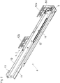
- Fig. 2 shows a drawer pull-out guide 4 in a perspective view, the carcass rail 9 being fastened to the furniture carcass 2 via the fastening sections 12a, 12b.
- the pull-out rail 10 is mounted displaceably relative to the carcass rail 9 and has a hook 13 at the rear end which, when the drawer 3 is assembled, engages in a pre-drilled hole in the rear wall 8 and thus a displacement of the rear end area of the drawer 3 in a direction transverse to the longitudinal direction ( L) prevents or limits the extending direction of the pull-out rail.
- a functional unit 14 is arranged at the front end region of the pull-out rail 10, which for reasons of a compact design is for the most part received within the pull-out rail 10.
- the pull-out rail 10 has a U-shaped profile section in cross section, the shape of the functional unit 14 being adapted at least in sections to the U-shaped profile section of the pull-out rail 10. It can be seen that the functional unit 14, preferably a plate-shaped section of the functional part 14, covers the front end area of the pull-out rail 10, which prevents the risk of injury from any sharp-edged end face of the pull-out rail 10.
- the center rail 11 is mounted displaceably between the body rail 9 and the pull-out rail 10. A movement of the pull-out rail 10 relative to the central rail 11 can be controlled by a toothed wheel 15 rotatably mounted on the central rail 11.
- the gear 15 works on the one hand with a first toothing 42a ( Figure 9a ) a first carriage 42, which is slidably mounted between the body rail 9 and the central rail 11, and on the other hand with a second rack of a second carriage 21 ( Fig. 3 ), which between the center rail 11 and the pull-out rail 10 is slidably mounted, together.
- the pull-out rail 10 can be moved in the longitudinal direction (L) during a movement at a higher, preferably approximately double, speed than the central rail 11.
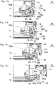
- Fig. 3 shows a front end area of the drawer pull-out guide 4 in the closed position, the pull-out rail 10 being hidden for the purpose of improved clarity.
- the pull-out rail 10 can be pulled into the closed position by means of a pull-in device 17 with at least one energy store 20, preferably with at least one tension spring.
- the retraction device 17 is attached to the pull-out rail 10 and has a movably mounted driver 18 which is pretensioned by the energy storage device 20 in the direction of the closed position and which is mounted to be displaceable along a linear guide track 22a by a guide element 18a.
- the driver 18 is detachably coupled to a coupling element 51 mounted on the carcass rail 9.
- the guide element 18a of the driver 18 is moved along the linear guide track 22a, the energy storage device 20 being charged. Subsequently, the driver 18 is tilted by the interaction of the guide element 18a with a section 22b bent or angled from the linear guide track 22a, so that the driver 18 is held on this section 22b in a self-locking, locked standby position with a charged energy store 20 and the coupling element 51 is released.
- the pull-out rail 10 can then be moved further in the direction of the open position in a manner that is decoupled from the pull-in device 17.
- a Damping device 23 is provided which, in the exemplary embodiment shown, has a, preferably hydraulic, piston-cylinder unit.
- the energy storage device 20, designed as a tension spring, and the housing, in particular the cylinder, of the damping device 23 are jointly supported on a bearing part 24 attached to the pull-out rail 10, the bearing part 24 and the functional unit 14 being designed as separate components.
- the second running carriage 21 can also be seen with a plurality of rolling bodies 21b spaced apart from one another in the longitudinal direction, the second running carriage 21 being slidably mounted between the center rail 11 and the pull-out rail 10.
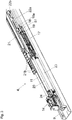
- Figure 4a shows the pull-out rail 10, with both the pull-in device 17 and the separate functional unit 14 in the assembly position being received for the most part (ie with more than 50% of the respective structural volume) within a, for example U-shaped, profile section of the pull-out rail 10.
- the draw-in device 17 has a housing 17a on which the linear guide track 22a and the bent or beveled section 22b for guiding the driver 18 are arranged or formed.
- a roller 26 mounted on the pull-out rail 10 the pull-out rail 10 can be supported in a vertical direction relative to the central rail 11.
- the pull-out rail 10 can be guided in a lateral direction relative to the central rail 11 by means of side rollers 27.
- the housing of the damping device 23 and the energy accumulator 20 in the form of the tension spring are mounted on the one hand with one end on the housing 17a of the retraction device 17, on the other hand on a bearing part 24 to be attached to the pull-out rail 10.
- the bearing part 24 is received in the assembly position within the pull-out rail 10 and is to be fastened, for example, by at least one pin 25 to a side web of the pull-out rail 10.
- Figure 5a shows the pull-out drawer slide 4 in a closed position, in which the end stop 28 of the functional unit 14 rests against a counter-stop 9a, preferably an end face, of the body rail 9, so that a Movement of the pull-out rail 10 relative to the body rail 9 in the direction of the closed position is limited.
- Figure 5b shows the in Figure 5a framed area in an enlarged view, wherein the coupling device 29 can be seen with the two coupling pieces 29a.
- the two coupling pieces 29a protrude upwards from an upper side of the pull-out rail 10 and engage in the carrier rail 35 ( Figure 6a ) of the drawer 3, a displacement of the drawer 3 relative to the pull-out rail 10 in the longitudinal direction (L) is prevented or limited by the arrangement of the rear hook 13 and the front coupling pieces 29a.
- the lift-off lock 31 of the functional unit 14 has a, for example semi-cylindrical, recess 31a into which a retaining lug 36 (not shown here) ( Figure 6b ) the support rail 35 engages, wherein a movement of the drawer 3 relative to the pull-out rail 10 in the vertical direction is prevented or limited by the retaining lug 36.
- the recess 31a is designed to be open towards the front, so that a retaining lug 36 ( Figure 6b ) the support rail 35 can be pushed into the recess 31a of the functional unit 14 from the front when the drawer 3 is mounted on the pull-out rail 10.
- the functional unit 14 is provided with a device 32 for the relative, preferably lateral, positioning of the drawer 3 relative to the pull-out rail 10, whereby it is preferably provided that the device 32 has at least one projection 32a which is attached to a carrier rail 35 connected to the drawer 3 can be applied.
- the projection 32a can optionally also be designed to be resilient, so that the drawer 3 can be arranged without play relative to the pull-out rail 10, preferably in at least one direction running transversely to the longitudinal direction (L).
- an actuating device 33 of a compensation device 30 for compensating for a misalignment of the at least one pull-out rail 10 and / or at least one carriage 21 deviating from a predefined relative position Arranged drawer pull-out guide 4, the actuating device 33 from the in Figure 4b shown stop 30a of the functional unit 14 can be actuated, the actuating device 33 of the compensation device 30 compensating for the misalignment when actuated by the stop 30a.
- a rail stop 34 in the form of an embossing is arranged at the front end of the body rail 9, the rail stop 34 being an extension movement of the first carriage 42 ( Figure 9a ), which is slidably mounted between the body rail 9 and the central rail 11, limited.
- Figure 6a shows a front portion of the drawer 3 in a perspective view.
- the carcass rail 9 of the drawer extension guide 4 is to be fastened to the furniture carcass 2 via the fastening section 12a; the center rail 11 and the pull-out rail 10 are mounted so as to be displaceable relative to the carcass rail 9.
- the drawer side wall 7 is connected to the support rail 35, which has a support 35a for supporting the drawer bottom 6.
- the front end region of the pull-out rail 10 can be releasably coupled relative to the carrier rail 35 via the coupling device 29 of the functional unit 14, the coupling pieces 29a engaging in corresponding recesses in the carrier rail 35.
- the support rail 35 has a retaining lug 36, preferably designed as an embossing, which engages in a recess 10a of the pull-out rail 10 so that movement of the drawer 3 relative to the pull-out rail 10 in the vertical direction is prevented or limited.
- the retaining lug 36 of the support rail 35 is in the mounting position in the recess 31a ( Figure 5b ) of the functional unit 14 was added.
- Figure 6b shows the in Figure 6a circled area in an enlarged view.
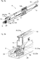
- Figure 7a shows the drawer extension slide 4 in a side view
- Figure 7b shows the in Figure 7a framed front end area of the drawer extension guide 4 in an enlarged view
- the actuating device 33 is arranged with a movably mounted actuating element 33a, which at a Movement of the pull-out rail 10 in the pull-out direction from the stop 30a of the functional unit 14 can be actuated.
- the actuating element 33a can be mounted on the front end of the center rail 11 so as to be pivotable about an axis which runs horizontally in the assembly position.
- the bearing part 24, on which the energy storage device 20 of the retraction device 17 and the housing of the damping device 23 are jointly mounted, is fastened to the pull-out rail 10.
- the bearing part 24 has a, preferably linear, support surface 37 which is spaced apart from the center rail 11 below a predetermined load on the pull-out rail 10, forming a gap 38.
- This situation is in Figure 7c shown which the in Figure 7b shows circled area in an enlarged view.
- the pull-out rail 10 in the front end area - by the arrangement of the second carriage 21 arranged between the center rail 11 and the pull-out rail 10 in the function of Pivot bearing - tilted upwards so that the support surface 37 of the bearing part 24 strikes the middle rail 11 and further tilting of the pull-out rail 10 is prevented ( Figure 7d ).
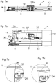
- Figure 8a shows the drawer extension guide 4, which is in the closed position, with the carcass rail 9, the center rail 11 and the pull-out rail 10 in a perspective view.
- Figure 8b shows the in Figure 8a circled area in an enlarged view.
- a bearing part 43 with the actuating device 33 is arranged, which can be actuated by the stop 30a arranged on the pull-out rail 10 if the carcass rail 9, the central rail 11 and the pull-out rail 10 are incorrectly positioned.
- Figure 8c shows a side view of the drawer extension slide 4
- Figure 8d shows the in Figure 8c framed front area in an enlarged view.
- the actuating device 33 has a movably, preferably pivotably, mounted actuating element 33a, which can be releasably coupled to the stop 30a in the event of an incorrect position.
- the actuating element 33a can for example have an arcuate circumferential surface, along which the stop 30a can be moved at least in sections.
- the actuating device 33 can be switched out of engagement with the pull-out rail 10, preferably the stop 30a, when the (correct) predefined relative position of the rails 9, 10, 11 is present.
- the switching device 46 has a movable switching element 46a, preferably mounted so as to be pivotable about an axis 48, which is connected in a movement-coupled manner to the actuating element 33a.
- the switching element 46a and the actuating element 33a are pivotably connected to one another via at least one moving hinge axis 45.
- the actuating element 33a and the switching element 46a are preloaded relative to one another by an energy store 44 in such a way that the actuating element 33a and the switching element 46a are pushed apart about the hinge axis 45 by the force of the energy store 44.
- the switching element 46a is mounted pivotably about the axis 48 and has a projection 46b which, in the closed position of the central rail 11, rests against a locking means 49, preferably a web, of the body rail 9.
- the locking means 49 prevents the switching element 46a from moving from the first switching position into the second switching position, if the rails 9, 10, 11 are in an incorrect position relative to one another.
- the rails 9, 10, 11 assume a correct, predefined position relative to one another.
- Figure 9a shows the drawer extension guide 4 in a cross section.
- a first carriage 42 with first load-transmitting rolling elements is mounted between the body rail 9 and the central rail 11, while a second carriage 21 is supported between the central rail 11 and the pull-out rail 10 second rolling elements 21b ( Fig. 3 ) is slidably arranged.
- the sequence of movements of the two carriages 42, 21 with respect to one another can be controlled by a synchronization device 40.
- the synchronization device 40 comprises a toothed wheel 15 rotatably mounted on the central rail 11, which meshes with a first toothing 42a of the (lower) first carriage 42 and with a second toothing 21a of the (upper) second carriage 21.
- the pull-out rail 10 is in a slightly open position.
- Figure 9b shows the in Figure 9a framed, front area of the drawer extension guide 4 in an enlarged view from which the compensation device 30 emerges in more detail.
- the body rail 9, the central rail 11 and the pull-out rail 10 are in a predefined, correct position relative to one another. If the pull-out rail 10 is now moved from its closed position in the pull-out direction 39, the switching element 46a arrives in a free position 47, so that the switching element 46a together with the actuating element 33a is tilted clockwise around the axis 48 in such a way that the one on the pull-out rail 11 arranged stop 30a can be moved further in the direction of the open position without hindrance by the actuating device 33.
- the clearance 47 can either be designed as a recess in the carcass rail 9, or - as shown in the figure - be formed by a free space located in the assembly position in front of the carcass rail 9, so that the projection 46b of the switching element 46a virtually travels into the void.
- the pull-out rail 11 moves against the pull-out direction 39, it can be moved back into the closed position without hindrance by the actuating device 33, the actuating element 33a being overridden by the stop 30a, if necessary, against the force of the energy accumulator 44.
- Figure 10a shows the pull-out drawer slide 4 in a perspective view, the rails 9, 10, 11 - for example due to a slip occurring between the carriage 21, 42 and the rails 9, 10, 11 - a assume a misalignment deviating from the predefined relative position.
- This can, for example, lead to the central rail 11 being positioned too far to the rear relative to the carcass rail 9, ie the carcass rail 9 and the central rail 11 being positioned over a contact point 50 ( Figure 10b ) are in contact with each other and there is therefore a misalignment to be corrected.
- Figure 10b shows the in Figure 10a circled area in an enlarged view.
- Figure 10c shows a side view of the drawer extension slide 4, while in Figure 10d the in Figure 10c framed front area of the drawer extension guide 4 is shown enlarged.
- the projection 46b of the switching element 46a rests on the locking means 49 of the body rail 9.
- the foremost area of the web of the body rail 9 can run obliquely downwards towards the front, as a result of which the friction is reduced and the tilting behavior of the switching element 46a is improved.
- Figures 11a-11d show a chronological sequence of the opening movement of the pull-out rail 10 in the pull-out direction 39 Figure 10d , in which there is a misalignment of the middle rail 11 relative to the body rail 9, the actuating element 33a of the actuating device 33 is contacted by the stop 30a of the pull-out rail 11 ( Figure 10a ).
- the projection 46b of the switching element 46a rests against the locking means 49 of the carcass rail 9, the locking means 49 preventing the switching element 46a from moving into a second, deactivated switching position of the switching element 46a, so the switching element 46a cannot be tilted about the axis 48.
- the pull-out rail 11 is thus coupled to the central rail 11 via the stop 30a and via the actuating element 33a.
- the pull-out rail 11 extends through the synchronization device 40 ( Figure 9a ) moves at a higher, preferably approximately double, speed than the central rail 11, the central rail 11 is briefly coupled to the higher speed of the pull-out rail 11.
- the middle rail 11 and the pull-out rail 10 are therefore the same when compensating for a misalignment Speed can be moved relative to the carcass rail 9, with the middle rail 11 being dragged over the rolling elements of the first carriage 42 ( Figures 11b, 11c ).
- the projection 46b of the switching element 46a can move back out over the front end of the cabinet rail 9, so that the switching element 46a is tilted about the axis 48 and the coupling between the actuating element 33a and the stop 30a of the pull-out rail 10 is thereby released.
- the middle rail 11 has in Figure 11d reaches its target position relative to the cabinet rail 9 again.
Landscapes
- Engineering & Computer Science (AREA)
- Mechanical Engineering (AREA)
- Drawers Of Furniture (AREA)
- Support Devices For Sliding Doors (AREA)
Claims (14)
- Glissière de guidage de tiroir (4), comprenant:- un rail de corps (9) à fixer à un corps de meuble (2),- au moins un rail télescopique (10), lequel est logé de façon déplaçable par rapport au rail de corps (9) entre une position de fermeture et une position d'ouverture,- un dispositif de repli (17) avec au moins un accumulateur d'énergie (20), dans lequel le rail télescopique (10) peut être replié dans la position de fermeture par la force du au moins un accumulateur d'énergie (20), dans laquelle le dispositif de repli (17) est disposé en majeure partie à l'intérieur du rail télescopique (10), dans laquelle le dispositif de repli (17) est fixé au rail télescopique (10),- une unité fonctionnelle (14), laquelle est disposée à une zone terminale avant du rail télescopique (10),- dans laquelle l'unité fonctionnelle (14) et le dispositif de repli (17) sont conçus comme des unités modulaires distinctes les unes des autres, dans laquelle le dispositif de repli (17) présente un toc d'entraînement (18) logé de façon mobile, lequel est précontraint par l'accumulateur d'énergie (20) dans le sens de la position de fermeture et lequel est logé de façon déplaçable par un élément de guidage (18a) le long d'une glissière de guidage linéaire (22a),caractérisée en ce que le dispositif de repli (17) et l'unité fonctionnelle (14) sont disposés d'une manière indépendante à différentes positions en profondeur du rail télescopique (10).
- Glissière de guidage de tiroir selon la revendication 1, caractérisée en ce que l'unité fonctionnelle (14) est réalisée comme un élément d'une seule pièce.
- Glissière de guidage de tiroir selon la revendication 1 ou 2, caractérisée en ce que l'unité fonctionnelle (14) est disposée en majeure partie à l'intérieur du rail télescopique (10).
- Glissière de guidage de tiroir selon l'une des revendications 1 à 3, caractérisée en ce que l'unité fonctionnelle (14) recouvre un côté frontal avant du rail télescopique (10).
- Glissière de guidage de tiroir selon l'une des revendications 1 à 4, caractérisée en ce que l'unité fonctionnelle (14)- présente au moins une butée terminale (28), laquelle stoppe un mouvement du rail télescopique (10) par rapport au rail de corps (9) dans le sens de la position de fermeture, dans laquelle il est prévu de préférence que la butée terminale (28) dépasse transversalement du rail télescopique (10) et bute dans la position de fermeture sur une contre-butée (9a) du rail de corps (9),
et / ou- présente au moins un dispositif d'accouplement (29) pour accoupler le rail télescopique (10) à un tiroir (3), dans laquelle il est prévu, de préférence, que le dispositif d'accouplement (29) présente au moins une pièce de jonction (29a), laquelle engrène, à l'état de montage du tiroir (3) sur le rail télescopique (10), dans un évidement d'un rail de support (35) relié au tiroir (3),
et / ou- présente un dispositif de compensation (30) pour la compensation d'une position erronée, différente d'une position relative prédéfinie, du au moins un rail télescopique (10) et / ou d'au moins un chariot (21, 42) de la glissière de guidage de tiroir (4), dans laquelle il est prévu de préférence que le dispositif de compensation (30) présente au moins une butée (30a) par laquelle un dispositif d'actionnement (33) du dispositif de compensation (30) peut être actionné, dans laquelle le dispositif d'actionnement (33) du dispositif de compensation (30), lors d'un actionnement par la butée (30a), compense la position erronée,
et / ou- présente un dispositif (32) pour le positionnement relatif, de préférence latéral, du tiroir (3) par rapport au rail télescopique (10), dans laquelle il est prévu, de préférence, que le dispositif (32) présente au moins une saillie (32a), laquelle peut être mise contre un rail de support (35) relié au tiroir (3),
et / ou
présente une sécurité anti-soulèvement (31), par laquelle un mouvement d'un tiroir (3), à l'état de montage sur le rail télescopique (10), est empêché ou limité dans le sens de la hauteur, dans laquelle il est prévu de préférence que la sécurité anti-soulèvement (31) présente au moins un évidement (31a), dans laquelle engrène, à l'état de montage du tiroir (3) sur le rail télescopique (10), un bec de retenue (36) d'un rail de support (35) relié au tiroir (3). - Glissière de guidage de tiroir selon l'une des revendications 1 à 5, caractérisée en ce que la glissière de guidage de tiroir (4) présente un rail médian (11), lequel est logé de façon déplaçable entre le rail de corps (9) et le rail télescopique (10).
- Glissière de guidage de tiroir selon l'une des revendications 1 à 6, caractérisée en ce qu'un dispositif amortisseur (23) est prévu pour amortir un mouvement du rail télescopique (10) dans la position de fermeture.
- Glissière de guidage de tiroir selon la revendication 7, caractérisée en ce que le dispositif amortisseur (23) présente une unité piston-cylindre.
- Glissière de guidage de tiroir selon la revendication 7 ou 8, caractérisée en ce que le dispositif amortisseur (23) et l'accumulateur d'énergie (20) du dispositif de repli (17) sont disposés sur une partie formant palier (24).
- Glissière de guidage de tiroir selon la revendication 9, caractérisée en ce que la partie formant palier (24) est fixée au rail télescopique (10).
- Glissière de guidage de tiroir selon la revendication 9 ou 10, caractérisée en ce que la partie formant palier (24) présente au moins une surface d'appui (37), conçue de préférence linéaire, pour appuyer le rail médian (11).
- Glissière de guidage de tiroir selon la revendication 11, caractérisée en ce que la surface d'appui (37) de la partie formant palier (24), au-dessous d'une charge prédéfinie du rail télescopique (10), est espacée du rail médian (11) en formant un intervalle (38) et en ce que la surface d'appui (37) de la partie formant palier (24), au-dessus de la charge prédéfinie par le rail télescopique (10), est adjacente au rail médian (11).
- Tiroir (3) avec au moins une glissière de guidage de tiroir (4) selon l'une des revendications 1 à 12.
- Meuble (1) avec un corps de meuble (2) et au moins un tiroir (3) selon la revendication 13, dans lequel le tiroir (3) est logé de façon mobile par rapport au corps de meuble (2) par la glissière de guidage de tiroir (4).
Priority Applications (1)
| Application Number | Priority Date | Filing Date | Title |
|---|---|---|---|
| EP21157140.1A EP3838068A1 (fr) | 2017-08-17 | 2018-07-10 | Guidage d'extension de tiroir |
Applications Claiming Priority (2)
| Application Number | Priority Date | Filing Date | Title |
|---|---|---|---|
| ATA50683/2017A AT520402A1 (de) | 2017-08-17 | 2017-08-17 | Schubladenausziehführung |
| PCT/AT2018/060143 WO2019033136A1 (fr) | 2017-08-17 | 2018-07-10 | Glissière télescopique pour tiroir |
Related Child Applications (1)
| Application Number | Title | Priority Date | Filing Date |
|---|---|---|---|
| EP21157140.1A Division EP3838068A1 (fr) | 2017-08-17 | 2018-07-10 | Guidage d'extension de tiroir |
Publications (2)
| Publication Number | Publication Date |
|---|---|
| EP3668350A1 EP3668350A1 (fr) | 2020-06-24 |
| EP3668350B1 true EP3668350B1 (fr) | 2021-02-24 |
Family
ID=62980964
Family Applications (2)
| Application Number | Title | Priority Date | Filing Date |
|---|---|---|---|
| EP18743381.8A Active EP3668350B1 (fr) | 2017-08-17 | 2018-07-10 | Glissière télescopique pour tiroir |
| EP21157140.1A Withdrawn EP3838068A1 (fr) | 2017-08-17 | 2018-07-10 | Guidage d'extension de tiroir |
Family Applications After (1)
| Application Number | Title | Priority Date | Filing Date |
|---|---|---|---|
| EP21157140.1A Withdrawn EP3838068A1 (fr) | 2017-08-17 | 2018-07-10 | Guidage d'extension de tiroir |
Country Status (9)
| Country | Link |
|---|---|
| US (1) | US11013320B2 (fr) |
| EP (2) | EP3668350B1 (fr) |
| JP (1) | JP6985497B2 (fr) |
| CN (1) | CN111050602B (fr) |
| AT (2) | AT17935U1 (fr) |
| ES (1) | ES2870010T3 (fr) |
| MY (1) | MY197930A (fr) |
| TW (1) | TWI685315B (fr) |
| WO (1) | WO2019033136A1 (fr) |
Families Citing this family (10)
| Publication number | Priority date | Publication date | Assignee | Title |
|---|---|---|---|---|
| CN114809846B (zh) * | 2018-04-02 | 2024-06-28 | 赛峰客舱公司 | 软式自关闭门用阻尼器 |
| DE102018108647A1 (de) * | 2018-04-11 | 2019-10-17 | Paul Hettich Gmbh & Co. Kg | Auszugsführung und Schubkastenserie |
| DE102019215448A1 (de) * | 2019-10-09 | 2021-04-15 | BSH Hausgeräte GmbH | Haushaltsgerät mit spezifischer Lagervorrichtung mit einer balkenartigen Lagerrinne für einen Schienenauszug |
| JP2022015039A (ja) * | 2020-07-08 | 2022-01-21 | タキゲン製造株式会社 | ソフトクローズ機構 |
| JP7493797B2 (ja) * | 2021-01-14 | 2024-06-03 | 日本アキュライド株式会社 | 自動引き込み装置付きスライドレール |
| CN115284915B (zh) * | 2022-09-03 | 2025-05-16 | 浙江非凡传媒科技有限公司 | 一种可移动调配式停车场充电系统 |
| US20260090643A1 (en) * | 2022-12-02 | 2026-04-02 | Samet Kalip Ve Madeni Esya San Ve Tic. A.S. | Extension guide |
| DE102023112548B3 (de) * | 2023-05-11 | 2024-08-14 | Fulterer Ag & Co Kg | Differenzialausziehführung |
| TWI834591B (zh) * | 2023-09-15 | 2024-03-01 | 川湖科技股份有限公司 | 滑軌總成 |
| DE102023004608B3 (de) * | 2023-11-14 | 2025-01-09 | Günther Zimmer | Nachrüstbares Beschleunigungs- und Verzögerungssystem |
Citations (4)
| Publication number | Priority date | Publication date | Assignee | Title |
|---|---|---|---|---|
| EP1483984A1 (fr) * | 2003-06-05 | 2004-12-08 | Grass AG | Glissière pour tiroirs |
| DE202007007773U1 (de) * | 2007-06-01 | 2007-08-30 | King Slide Works Co., Ltd., Lu-Chu Hsiang | Verbindung von Schublade und Gleitschiene |
| AT9972U1 (de) * | 2007-04-10 | 2008-07-15 | Grass Gmbh | Ausziehführung für schubladen |
| DE202008012996U1 (de) * | 2008-09-30 | 2010-02-18 | Paul Hettich Gmbh & Co. Kg | Möbelauszugsführung |
Family Cites Families (41)
| Publication number | Priority date | Publication date | Assignee | Title |
|---|---|---|---|---|
| AT9972B (de) | 1901-10-09 | 1902-11-25 | Hanns Prescher | Stockzünder für Gaslampen und Gaslaternen. |
| DE4325920C2 (de) * | 1993-08-02 | 1997-12-18 | Mauro Romagnoni | Ausziehsperre für Möbelauszüge |
| AT401715B (de) | 1994-01-17 | 1996-11-25 | Blum Gmbh Julius | Differentialauszug für schubladen |
| US20040201339A1 (en) * | 2003-04-10 | 2004-10-14 | Maytag Corporation | Rail stop for dishwasher rack rail |
| DE202005006724U1 (de) * | 2005-02-14 | 2005-07-28 | Grass Gmbh | Schubladenführung |
| MY139488A (en) * | 2005-06-09 | 2009-10-30 | Harn Marketing Sdn Bhd | Closing device |
| TWM292326U (en) * | 2005-12-16 | 2006-06-21 | Martas Prec Slide Co Ltd | Closure buffer structure of sliding track |
| AT505053B1 (de) * | 2007-04-02 | 2009-02-15 | Fulterer Gmbh | Rollen-differentialausziehführung |
| US7695080B2 (en) * | 2007-06-05 | 2010-04-13 | King Slide Works Co., Ltd. | Securing device for a drawer slide |
| US8911039B2 (en) * | 2007-10-02 | 2014-12-16 | Paul Hettich Gmbh & Co. Kg | Pull-out guide having a self-retracting device |
| DE202008003328U1 (de) * | 2007-10-02 | 2009-02-12 | Paul Hettich Gmbh & Co. Kg | Auszugsführung mit einer Selbsteinzugsvorrichtung |
| DE202008016409U1 (de) * | 2008-12-13 | 2010-04-22 | Paul Hettich Gmbh & Co. Kg | Selbsteinzugsvorrichtung und Auszugsführung |
| DE202009002715U1 (de) * | 2009-02-25 | 2010-07-15 | Paul Hettich Gmbh & Co. Kg | Auszugsführung für ein Möbelauszugsteil |
| MY151706A (en) * | 2009-08-12 | 2014-06-30 | Harn Marketing Sdn Bhd | Drawer assembly |
| US8632141B2 (en) * | 2009-08-12 | 2014-01-21 | Segos Co., Ltd. | Sliding apparatus with self-closing means |
| US20110043087A1 (en) * | 2009-08-19 | 2011-02-24 | Hui-Chu Shih | Slide rail buffering structure |
| AT508140B1 (de) * | 2009-10-29 | 2010-11-15 | Blum Gmbh Julius | Ein- oder auszugsvorrichtung zum bewegen eines bewegbaren möbelteiles |
| DE102010017132B4 (de) * | 2010-05-28 | 2020-10-01 | Paul Hettich Gmbh & Co. Kg | Schrankmöbel mit einem Frontschubkasten und einem Innenschubkasten |
| DE202010008079U1 (de) * | 2010-07-14 | 2010-09-09 | Anton Schneider Gmbh & Co Kg | Ausziehführung für Schubladen |
| AT510018B1 (de) * | 2010-11-23 | 2012-01-15 | Blum Gmbh Julius | Vorrichtung zur anbringung eines funktionsteiles an einer schiene einer schubladenausziehführung |
| AT511294B1 (de) * | 2011-04-11 | 2013-06-15 | Blum Gmbh Julius | Schubladenausziehführung |
| AT511081B1 (de) * | 2011-05-05 | 2012-09-15 | Blum Gmbh Julius | Anordnung mit einer schublade und mit einer schubladenausziehführung |
| TWM440036U (en) * | 2012-01-12 | 2012-11-01 | Nan Juen Int Co Ltd | Improved automatic homing rail buffer structure |
| AT513330B1 (de) * | 2012-08-27 | 2017-04-15 | Blum Gmbh Julius | Dämpfvorrichtung für bewegbare Möbelteile |
| DE102013102944B4 (de) * | 2012-10-12 | 2024-05-16 | Paul Hettich Gmbh & Co. Kg | Auszugsführung |
| AT512934B1 (de) * | 2012-11-12 | 2013-12-15 | Blum Gmbh Julius | Schubladenausziehführung |
| DE202014104926U1 (de) * | 2014-10-16 | 2016-01-19 | Grass Gmbh | Wandbauteil, Schublade mit einem solchen Wandbauteil und Möbel |
| US20160198855A1 (en) * | 2015-01-13 | 2016-07-14 | King Slide Works Co., Ltd. | Slide rail assembly and mounting device thereof |
| CN104997304B (zh) * | 2015-08-12 | 2017-09-05 | 伍志勇 | 拉篮与滑轨的连接结构 |
| TWI601499B (zh) * | 2015-09-25 | 2017-10-11 | Side lock slide automatic opening device | |
| TWI548369B (zh) * | 2015-10-06 | 2016-09-11 | King Slide Works Co Ltd | 用於滑軌總成的安裝配件 |
| AT517479B1 (de) * | 2015-10-28 | 2017-02-15 | Blum Gmbh Julius | Schubladenausziehführung |
| TWI548370B (zh) * | 2015-11-12 | 2016-09-11 | 川湖科技股份有限公司 | 快拆式滑軌組件 |
| US10314398B2 (en) * | 2015-12-17 | 2019-06-11 | Grass America, Inc. | Pull-out guide for the guidance of a drawer |
| DE102016105231A1 (de) * | 2016-03-21 | 2017-09-21 | Paul Hettich Gmbh & Co. Kg | Auszugsführung und Haushaltsgerät |
| AT518398B1 (de) * | 2016-04-05 | 2017-10-15 | Blum Gmbh Julius | Möbelantrieb |
| DE102016116449A1 (de) * | 2016-09-02 | 2018-03-08 | Paul Hettich Gmbh & Co. Kg | Selbsteinzugs- und Dämpfungsvorrichtung für ein Schubelement und Möbel oder Haushaltsgerät mit mindestens einem Schubelement |
| TWI616164B (zh) * | 2017-03-07 | 2018-03-01 | 川湖科技股份有限公司 | 用於傢俱部件的連接機構與滑軌總成 |
| CN207411858U (zh) * | 2017-04-19 | 2018-05-29 | 江井金属股份有限公司 | 具有检视视窗的自锁式滑轨组 |
| AT519982B1 (de) * | 2017-08-17 | 2018-12-15 | Blum Gmbh Julius | Schubladenausziehführung |
| AT18003U1 (de) * | 2017-08-30 | 2023-10-15 | Blum Gmbh Julius | Schubladenausziehführung |
-
2017
- 2017-08-17 AT ATGM8014/2022U patent/AT17935U1/de unknown
- 2017-08-17 AT ATA50683/2017A patent/AT520402A1/de active IP Right Grant
-
2018
- 2018-07-10 MY MYPI2020000543A patent/MY197930A/en unknown
- 2018-07-10 EP EP18743381.8A patent/EP3668350B1/fr active Active
- 2018-07-10 JP JP2020508511A patent/JP6985497B2/ja active Active
- 2018-07-10 ES ES18743381T patent/ES2870010T3/es active Active
- 2018-07-10 WO PCT/AT2018/060143 patent/WO2019033136A1/fr not_active Ceased
- 2018-07-10 EP EP21157140.1A patent/EP3838068A1/fr not_active Withdrawn
- 2018-07-10 CN CN201880052766.0A patent/CN111050602B/zh active Active
- 2018-07-24 TW TW107125462A patent/TWI685315B/zh active
-
2020
- 2020-01-22 US US16/749,274 patent/US11013320B2/en active Active
Patent Citations (4)
| Publication number | Priority date | Publication date | Assignee | Title |
|---|---|---|---|---|
| EP1483984A1 (fr) * | 2003-06-05 | 2004-12-08 | Grass AG | Glissière pour tiroirs |
| AT9972U1 (de) * | 2007-04-10 | 2008-07-15 | Grass Gmbh | Ausziehführung für schubladen |
| DE202007007773U1 (de) * | 2007-06-01 | 2007-08-30 | King Slide Works Co., Ltd., Lu-Chu Hsiang | Verbindung von Schublade und Gleitschiene |
| DE202008012996U1 (de) * | 2008-09-30 | 2010-02-18 | Paul Hettich Gmbh & Co. Kg | Möbelauszugsführung |
Also Published As
| Publication number | Publication date |
|---|---|
| JP6985497B2 (ja) | 2021-12-22 |
| TWI685315B (zh) | 2020-02-21 |
| CN111050602B (zh) | 2022-01-14 |
| US20200154885A1 (en) | 2020-05-21 |
| EP3838068A1 (fr) | 2021-06-23 |
| WO2019033136A1 (fr) | 2019-02-21 |
| CN111050602A (zh) | 2020-04-21 |
| AT520402A1 (de) | 2019-03-15 |
| EP3668350A1 (fr) | 2020-06-24 |
| TW201919516A (zh) | 2019-06-01 |
| MY197930A (en) | 2023-07-25 |
| US11013320B2 (en) | 2021-05-25 |
| ES2870010T3 (es) | 2021-10-26 |
| JP2020530799A (ja) | 2020-10-29 |
| AT17935U1 (de) | 2023-08-15 |
Similar Documents
| Publication | Publication Date | Title |
|---|---|---|
| EP3668350B1 (fr) | Glissière télescopique pour tiroir | |
| EP2916688B1 (fr) | Glissière télescopique de tiroir | |
| EP3244775B1 (fr) | Dispositif d'entrainement pour meuble | |
| AT519120B1 (de) | Schienenanordnung für Möbelteile | |
| EP3838069B1 (fr) | Guidage d'extension de tiroir | |
| EP2373195B1 (fr) | Dispositif de rentrée automatique et glissière | |
| EP3668351B1 (fr) | Glissière de sortie pour tiroir | |
| EP3071071B1 (fr) | Dispositif d'amortissement | |
| EP3393301B1 (fr) | Assemblage de tiroir | |
| EP1500763B1 (fr) | Dispositif pour empêcher l'ouverture simultanée de tiroirs | |
| EP3745918B1 (fr) | Rail de chargement pour une glissière télescopique de tiroir | |
| EP3092919B2 (fr) | Dispositif de guidage pour le guidage d'une piece de meuble mobile par rapport à un corps de meuble | |
| EP1743550B1 (fr) | Dispositif de déplacement pour extensions de meuble, en particulier tiroirs | |
| EP0957714B1 (fr) | Coulisse encastree de guidage de sortie pour tiroirs etc. | |
| EP4077850B1 (fr) | Système de guidage permettant de guider un battant de porte monté de manière mobile | |
| EP4385363B1 (fr) | Ensemble comprenant un dispositif d'entraînement et un dispositif de synchronisation pour glissières télescopiques d'un tiroir | |
| AT520805B1 (de) | Ausziehführung | |
| WO2017070722A1 (fr) | Guidage télescopique pour tiroir | |
| EP3928036B1 (fr) | Appareil de cuisson muni d'une unité d'amortissement spécifique entre des glissières d'un dispositif de guidage pour une porte escamotable | |
| DE202008012996U1 (de) | Möbelauszugsführung | |
| AT520673B1 (de) | Bewegungsmechanismus für ein Führungssystem | |
| EP3563724B1 (fr) | Dispositif de fermeture d'une partie de meuble mobile | |
| EP2939879B1 (fr) | Plancher de chargement télescopique d'un véhicule automobile | |
| WO2008052505A1 (fr) | Toit ouvrant de véhicule avec déflecteur relevable |
Legal Events
| Date | Code | Title | Description |
|---|---|---|---|
| STAA | Information on the status of an ep patent application or granted ep patent |
Free format text: STATUS: UNKNOWN |
|
| STAA | Information on the status of an ep patent application or granted ep patent |
Free format text: STATUS: THE INTERNATIONAL PUBLICATION HAS BEEN MADE |
|
| PUAI | Public reference made under article 153(3) epc to a published international application that has entered the european phase |
Free format text: ORIGINAL CODE: 0009012 |
|
| STAA | Information on the status of an ep patent application or granted ep patent |
Free format text: STATUS: REQUEST FOR EXAMINATION WAS MADE |
|
| 17P | Request for examination filed |
Effective date: 20200115 |
|
| AK | Designated contracting states |
Kind code of ref document: A1 Designated state(s): AL AT BE BG CH CY CZ DE DK EE ES FI FR GB GR HR HU IE IS IT LI LT LU LV MC MK MT NL NO PL PT RO RS SE SI SK SM TR |
|
| AX | Request for extension of the european patent |
Extension state: BA ME |
|
| STAA | Information on the status of an ep patent application or granted ep patent |
Free format text: STATUS: EXAMINATION IS IN PROGRESS |
|
| 17Q | First examination report despatched |
Effective date: 20200730 |
|
| GRAP | Despatch of communication of intention to grant a patent |
Free format text: ORIGINAL CODE: EPIDOSNIGR1 |
|
| STAA | Information on the status of an ep patent application or granted ep patent |
Free format text: STATUS: GRANT OF PATENT IS INTENDED |
|
| DAV | Request for validation of the european patent (deleted) | ||
| DAX | Request for extension of the european patent (deleted) | ||
| INTG | Intention to grant announced |
Effective date: 20201125 |
|
| GRAS | Grant fee paid |
Free format text: ORIGINAL CODE: EPIDOSNIGR3 |
|
| GRAA | (expected) grant |
Free format text: ORIGINAL CODE: 0009210 |
|
| STAA | Information on the status of an ep patent application or granted ep patent |
Free format text: STATUS: THE PATENT HAS BEEN GRANTED |
|
| AK | Designated contracting states |
Kind code of ref document: B1 Designated state(s): AL AT BE BG CH CY CZ DE DK EE ES FI FR GB GR HR HU IE IS IT LI LT LU LV MC MK MT NL NO PL PT RO RS SE SI SK SM TR |
|
| REG | Reference to a national code |
Ref country code: CH Ref legal event code: EP |
|
| REG | Reference to a national code |
Ref country code: AT Ref legal event code: REF Ref document number: 1363393 Country of ref document: AT Kind code of ref document: T Effective date: 20210315 |
|
| REG | Reference to a national code |
Ref country code: IE Ref legal event code: FG4D Free format text: LANGUAGE OF EP DOCUMENT: GERMAN |
|
| REG | Reference to a national code |
Ref country code: DE Ref legal event code: R096 Ref document number: 502018004068 Country of ref document: DE |
|
| REG | Reference to a national code |
Ref country code: LT Ref legal event code: MG9D |
|
| REG | Reference to a national code |
Ref country code: NL Ref legal event code: MP Effective date: 20210224 |
|
| PG25 | Lapsed in a contracting state [announced via postgrant information from national office to epo] |
Ref country code: NO Free format text: LAPSE BECAUSE OF FAILURE TO SUBMIT A TRANSLATION OF THE DESCRIPTION OR TO PAY THE FEE WITHIN THE PRESCRIBED TIME-LIMIT Effective date: 20210524 Ref country code: PT Free format text: LAPSE BECAUSE OF FAILURE TO SUBMIT A TRANSLATION OF THE DESCRIPTION OR TO PAY THE FEE WITHIN THE PRESCRIBED TIME-LIMIT Effective date: 20210624 Ref country code: LT Free format text: LAPSE BECAUSE OF FAILURE TO SUBMIT A TRANSLATION OF THE DESCRIPTION OR TO PAY THE FEE WITHIN THE PRESCRIBED TIME-LIMIT Effective date: 20210224 Ref country code: BG Free format text: LAPSE BECAUSE OF FAILURE TO SUBMIT A TRANSLATION OF THE DESCRIPTION OR TO PAY THE FEE WITHIN THE PRESCRIBED TIME-LIMIT Effective date: 20210524 Ref country code: FI Free format text: LAPSE BECAUSE OF FAILURE TO SUBMIT A TRANSLATION OF THE DESCRIPTION OR TO PAY THE FEE WITHIN THE PRESCRIBED TIME-LIMIT Effective date: 20210224 Ref country code: HR Free format text: LAPSE BECAUSE OF FAILURE TO SUBMIT A TRANSLATION OF THE DESCRIPTION OR TO PAY THE FEE WITHIN THE PRESCRIBED TIME-LIMIT Effective date: 20210224 Ref country code: GR Free format text: LAPSE BECAUSE OF FAILURE TO SUBMIT A TRANSLATION OF THE DESCRIPTION OR TO PAY THE FEE WITHIN THE PRESCRIBED TIME-LIMIT Effective date: 20210525 |
|
| PG25 | Lapsed in a contracting state [announced via postgrant information from national office to epo] |
Ref country code: SE Free format text: LAPSE BECAUSE OF FAILURE TO SUBMIT A TRANSLATION OF THE DESCRIPTION OR TO PAY THE FEE WITHIN THE PRESCRIBED TIME-LIMIT Effective date: 20210224 Ref country code: RS Free format text: LAPSE BECAUSE OF FAILURE TO SUBMIT A TRANSLATION OF THE DESCRIPTION OR TO PAY THE FEE WITHIN THE PRESCRIBED TIME-LIMIT Effective date: 20210224 Ref country code: LV Free format text: LAPSE BECAUSE OF FAILURE TO SUBMIT A TRANSLATION OF THE DESCRIPTION OR TO PAY THE FEE WITHIN THE PRESCRIBED TIME-LIMIT Effective date: 20210224 Ref country code: PL Free format text: LAPSE BECAUSE OF FAILURE TO SUBMIT A TRANSLATION OF THE DESCRIPTION OR TO PAY THE FEE WITHIN THE PRESCRIBED TIME-LIMIT Effective date: 20210224 Ref country code: NL Free format text: LAPSE BECAUSE OF FAILURE TO SUBMIT A TRANSLATION OF THE DESCRIPTION OR TO PAY THE FEE WITHIN THE PRESCRIBED TIME-LIMIT Effective date: 20210224 |
|
| PG25 | Lapsed in a contracting state [announced via postgrant information from national office to epo] |
Ref country code: IS Free format text: LAPSE BECAUSE OF FAILURE TO SUBMIT A TRANSLATION OF THE DESCRIPTION OR TO PAY THE FEE WITHIN THE PRESCRIBED TIME-LIMIT Effective date: 20210624 |
|
| REG | Reference to a national code |
Ref country code: ES Ref legal event code: FG2A Ref document number: 2870010 Country of ref document: ES Kind code of ref document: T3 Effective date: 20211026 |
|
| PG25 | Lapsed in a contracting state [announced via postgrant information from national office to epo] |
Ref country code: SM Free format text: LAPSE BECAUSE OF FAILURE TO SUBMIT A TRANSLATION OF THE DESCRIPTION OR TO PAY THE FEE WITHIN THE PRESCRIBED TIME-LIMIT Effective date: 20210224 Ref country code: EE Free format text: LAPSE BECAUSE OF FAILURE TO SUBMIT A TRANSLATION OF THE DESCRIPTION OR TO PAY THE FEE WITHIN THE PRESCRIBED TIME-LIMIT Effective date: 20210224 Ref country code: CZ Free format text: LAPSE BECAUSE OF FAILURE TO SUBMIT A TRANSLATION OF THE DESCRIPTION OR TO PAY THE FEE WITHIN THE PRESCRIBED TIME-LIMIT Effective date: 20210224 |
|
| REG | Reference to a national code |
Ref country code: DE Ref legal event code: R097 Ref document number: 502018004068 Country of ref document: DE |
|
| PG25 | Lapsed in a contracting state [announced via postgrant information from national office to epo] |
Ref country code: DK Free format text: LAPSE BECAUSE OF FAILURE TO SUBMIT A TRANSLATION OF THE DESCRIPTION OR TO PAY THE FEE WITHIN THE PRESCRIBED TIME-LIMIT Effective date: 20210224 Ref country code: SK Free format text: LAPSE BECAUSE OF FAILURE TO SUBMIT A TRANSLATION OF THE DESCRIPTION OR TO PAY THE FEE WITHIN THE PRESCRIBED TIME-LIMIT Effective date: 20210224 Ref country code: RO Free format text: LAPSE BECAUSE OF FAILURE TO SUBMIT A TRANSLATION OF THE DESCRIPTION OR TO PAY THE FEE WITHIN THE PRESCRIBED TIME-LIMIT Effective date: 20210224 |
|
| PLBE | No opposition filed within time limit |
Free format text: ORIGINAL CODE: 0009261 |
|
| STAA | Information on the status of an ep patent application or granted ep patent |
Free format text: STATUS: NO OPPOSITION FILED WITHIN TIME LIMIT |
|
| PG25 | Lapsed in a contracting state [announced via postgrant information from national office to epo] |
Ref country code: AL Free format text: LAPSE BECAUSE OF FAILURE TO SUBMIT A TRANSLATION OF THE DESCRIPTION OR TO PAY THE FEE WITHIN THE PRESCRIBED TIME-LIMIT Effective date: 20210224 |
|
| 26N | No opposition filed |
Effective date: 20211125 |
|
| REG | Reference to a national code |
Ref country code: CH Ref legal event code: PL |
|
| PG25 | Lapsed in a contracting state [announced via postgrant information from national office to epo] |
Ref country code: MC Free format text: LAPSE BECAUSE OF FAILURE TO SUBMIT A TRANSLATION OF THE DESCRIPTION OR TO PAY THE FEE WITHIN THE PRESCRIBED TIME-LIMIT Effective date: 20210224 |
|
| REG | Reference to a national code |
Ref country code: BE Ref legal event code: MM Effective date: 20210731 |
|
| PG25 | Lapsed in a contracting state [announced via postgrant information from national office to epo] |
Ref country code: LI Free format text: LAPSE BECAUSE OF NON-PAYMENT OF DUE FEES Effective date: 20210731 Ref country code: CH Free format text: LAPSE BECAUSE OF NON-PAYMENT OF DUE FEES Effective date: 20210731 |
|
| PG25 | Lapsed in a contracting state [announced via postgrant information from national office to epo] |
Ref country code: IS Free format text: LAPSE BECAUSE OF FAILURE TO SUBMIT A TRANSLATION OF THE DESCRIPTION OR TO PAY THE FEE WITHIN THE PRESCRIBED TIME-LIMIT Effective date: 20210624 Ref country code: LU Free format text: LAPSE BECAUSE OF NON-PAYMENT OF DUE FEES Effective date: 20210710 Ref country code: FR Free format text: LAPSE BECAUSE OF NON-PAYMENT OF DUE FEES Effective date: 20210731 |
|
| PG25 | Lapsed in a contracting state [announced via postgrant information from national office to epo] |
Ref country code: IE Free format text: LAPSE BECAUSE OF NON-PAYMENT OF DUE FEES Effective date: 20210710 Ref country code: BE Free format text: LAPSE BECAUSE OF NON-PAYMENT OF DUE FEES Effective date: 20210731 |
|
| GBPC | Gb: european patent ceased through non-payment of renewal fee |
Effective date: 20220710 |
|
| PG25 | Lapsed in a contracting state [announced via postgrant information from national office to epo] |
Ref country code: GB Free format text: LAPSE BECAUSE OF NON-PAYMENT OF DUE FEES Effective date: 20220710 |
|
| P01 | Opt-out of the competence of the unified patent court (upc) registered |
Effective date: 20230523 |
|
| PG25 | Lapsed in a contracting state [announced via postgrant information from national office to epo] |
Ref country code: CY Free format text: LAPSE BECAUSE OF FAILURE TO SUBMIT A TRANSLATION OF THE DESCRIPTION OR TO PAY THE FEE WITHIN THE PRESCRIBED TIME-LIMIT Effective date: 20210224 |
|
| PG25 | Lapsed in a contracting state [announced via postgrant information from national office to epo] |
Ref country code: HU Free format text: LAPSE BECAUSE OF FAILURE TO SUBMIT A TRANSLATION OF THE DESCRIPTION OR TO PAY THE FEE WITHIN THE PRESCRIBED TIME-LIMIT; INVALID AB INITIO Effective date: 20180710 |
|
| PG25 | Lapsed in a contracting state [announced via postgrant information from national office to epo] |
Ref country code: SI Free format text: LAPSE BECAUSE OF FAILURE TO SUBMIT A TRANSLATION OF THE DESCRIPTION OR TO PAY THE FEE WITHIN THE PRESCRIBED TIME-LIMIT Effective date: 20210224 |
|
| PG25 | Lapsed in a contracting state [announced via postgrant information from national office to epo] |
Ref country code: MK Free format text: LAPSE BECAUSE OF FAILURE TO SUBMIT A TRANSLATION OF THE DESCRIPTION OR TO PAY THE FEE WITHIN THE PRESCRIBED TIME-LIMIT Effective date: 20210224 |
|
| PG25 | Lapsed in a contracting state [announced via postgrant information from national office to epo] |
Ref country code: MT Free format text: LAPSE BECAUSE OF FAILURE TO SUBMIT A TRANSLATION OF THE DESCRIPTION OR TO PAY THE FEE WITHIN THE PRESCRIBED TIME-LIMIT Effective date: 20210224 |
|
| PGFP | Annual fee paid to national office [announced via postgrant information from national office to epo] |
Ref country code: ES Payment date: 20250812 Year of fee payment: 8 |
|
| PGFP | Annual fee paid to national office [announced via postgrant information from national office to epo] |
Ref country code: DE Payment date: 20250728 Year of fee payment: 8 |
|
| PGFP | Annual fee paid to national office [announced via postgrant information from national office to epo] |
Ref country code: IT Payment date: 20250721 Year of fee payment: 8 Ref country code: TR Payment date: 20250708 Year of fee payment: 8 |
|
| PGFP | Annual fee paid to national office [announced via postgrant information from national office to epo] |
Ref country code: AT Payment date: 20250729 Year of fee payment: 8 |