EP3670815A1 - Système d'actionnement destiné à l'actionnement motorisé d'un dispositif de verrouillage pour une ouverture d'un mur ou d'actionnement d'un dispositif d'obscurcissement - Google Patents
Système d'actionnement destiné à l'actionnement motorisé d'un dispositif de verrouillage pour une ouverture d'un mur ou d'actionnement d'un dispositif d'obscurcissement Download PDFInfo
- Publication number
- EP3670815A1 EP3670815A1 EP19215616.4A EP19215616A EP3670815A1 EP 3670815 A1 EP3670815 A1 EP 3670815A1 EP 19215616 A EP19215616 A EP 19215616A EP 3670815 A1 EP3670815 A1 EP 3670815A1
- Authority
- EP
- European Patent Office
- Prior art keywords
- housing
- electrical
- connector
- energy store
- actuating system
- Prior art date
- Legal status (The legal status is an assumption and is not a legal conclusion. Google has not performed a legal analysis and makes no representation as to the accuracy of the status listed.)
- Granted
Links
Images




Classifications
-
- E—FIXED CONSTRUCTIONS
- E06—DOORS, WINDOWS, SHUTTERS, OR ROLLER BLINDS IN GENERAL; LADDERS
- E06B—FIXED OR MOVABLE CLOSURES FOR OPENINGS IN BUILDINGS, VEHICLES, FENCES OR LIKE ENCLOSURES IN GENERAL, e.g. DOORS, WINDOWS, BLINDS, GATES
- E06B9/00—Screening or protective devices for wall or similar openings, with or without operating or securing mechanisms; Closures of similar construction
- E06B9/02—Shutters, movable grilles, or other safety closing devices, e.g. against burglary
- E06B9/08—Roll-type closures
- E06B9/11—Roller shutters
- E06B9/17—Parts or details of roller shutters, e.g. suspension devices, shutter boxes, wicket doors, ventilation openings
- E06B9/17007—Shutter boxes; Details or component parts thereof
Definitions
- Out DE 20 2016 105 745 U1 is a roller shutter drive system with an electric drive, which is designed for arrangement in a roller shutter box, with a battery and with a charging device.
- the battery is integrated in the electric drive.
- a feed-through device with a feed-through is provided for connecting a charging cable, which feed-through device is guided through a wall of the roller shutter box and is fastened to the wall.
- the bushing has a charging socket or a charging plug for the charging cable.
- the window system comprises a window and a shielding arrangement with a shielding device, which can be a roller shutter, and at least one device element.
- the device element is detachably connected to a rail in a component of the window or the shielding device and is interchangeable between them.
- the invention has the very special advantage that the closure device or the darkening device can be made smaller because no storage space is required for an energy store within the closure device or the darkening device.
- the empty electrical energy store can, for example, be recharged on a central charger, preferably in the vicinity of a 230 V socket.
- no energy store in particular no energy store for operating the electric motor, is preferably arranged in the first housing.
- the actuation system can advantageously be designed such that there are no flexible electrical cables outside the first housing and outside the second housing.
- the guide has a first guide element and a second guide element, the first guide element being part of the holder and the second guide element being part of the second housing.
- the first electrical connector is constructed in several parts and has at least one intermediate connector.
- Analog can alternatively or it can also be advantageously provided that the second electrical connector is constructed in several parts and has at least one intermediate connector.
- the adapter plug can have, for example, two adapter plug connectors arranged at the ends of an inflexible, in particular rigid, tube, which are electrically connected to one another by means of at least one line running through the tube 15.
- Such an embodiment makes it possible for the first housing and the second housing to each have a plug connector, while the intermediate plug plug connector is designed as a plug.
- Such a design is particularly robust because protruding parts on the housings are avoided. In particular, the risk is reduced that one of the plug connectors will be damaged from the holder during assembly of the system and / or when the fixing movement is carried out and / or when the second housing is released.
- the holder can advantageously have an intermediate connector holding section, on which the intermediate connector, in particular non-destructively and / or without tools, can be detached again.
- the bracket section can be firmly connected to the remaining part of the bracket or can be made in one piece with the remaining part of the bracket.
- the mounting section can be designed as a separate component which is connected to the rest of the mounting during assembly and / or is mounted separately from the mounting.
- the adapter plug can have a straight tube. However, it is also advantageously possible for the adapter plug to have an angled, rigid tube or a bent rigid tube. In this way it is possible to be able to adapt the arrangement of the holder relative to the first housing to the respective installation space conditions at the installation site.
- the adapter plug can alternatively be designed to be plastically bendable or elastically bendable. Such a design can be used particularly flexibly.
- the holder is a component separate from the first housing, which is fastened separately, for example by means of fastening screws and / or by an adhesive connection, to a wall of a building or to the ceiling of a building or to a reveal, in particular a window reveal or door reveal or gate reveal .
- the first housing can in particular act as a roller shutter box or a blind box or can be part of a roller shutter box or a blind box.
- the holder is preferably not held directly and / or exclusively by the first housing.
- the holder is preferably not held directly and / or exclusively by the first housing on a wall, a ceiling or a reveal.
- the holder is preferably not part of the first Housing.
- the holder is preferably not connected directly to the first housing.
- the holder is preferably not formed by a part of a roller shutter box or a blind box, in particular not by a housing of a roller shutter box or blind box.
- the holder is designed and intended to be attached vertically to a wall or horizontally overhead to a ceiling or reveal.
- the holder can have through holes, for example, through which fastening screws can be guided.
- the second housing carries a third connector which is electrically connected to the second connector and / or the energy store.
- the further electrical component can be, for example, a further consumer that draws energy from the energy store.
- a third housing which contains a second energy store and which carries a fourth connector which is electrically connected to the second electrical energy store.
- the fourth connector can be formed in several parts.
- the fourth connector has at least one second adapter.
- the third housing together with the second energy store is constructed identically to the second housing including its energy store.
- the third housing can advantageously have a fifth electrical connector, which allows the connection of further electrical components.
- the specified first energy store and the specified second energy store are electrically connected in parallel.
- Such an embodiment has the particular advantage that a higher electric current can be supplied to the electric drive at the same supply voltage. This is advantageous, for example, if the electric drive has to operate a particularly heavy roller shutter.
- the specified first energy store and the specified second energy store are electrically connected in series. In such an embodiment, a supply voltage which is doubled compared to the use of only one energy store is available.
- the actuation system emits an acoustic and / or visual warning signal when the energy storage device falls below a certain or predeterminable charge state.
- the output of an acoustic warning signal has the very special advantage that the user perceives a charge state that is too low even if parts of the actuation system, in particular a warning light for emitting an optical warning signal, are covered by a curtain.
- the actuation system can be designed, for example, as a belt winder or as a roller shutter actuation system or as a blind actuation system or as a window vent or as a door actuation system.
- Also of particular advantage is a system which has an actuation system according to the invention and a darkening device, in particular a roller shutter or a blind.
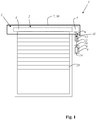
- Fig. 1 shows a first embodiment of an actuation system 1 according to the invention for motorized actuation of a blackout device 2, namely a roller shutter 3, which has a roller shutter curtain 25 and a winding roll 4.
- the actuation system 1 has an electrical drive 5 for rotating the winding roll 4 and an electrical energy store 6 in which energy for operating the electrical drive 5 is stored or can be stored.
- the actuation system 1 also has a first housing 7, which contains the electrical drive 5, but not the electrical energy store 6.
- the first housing 7 carries a first electrical connector 8, which is electrically connected to the electrical drive 5.
- the actuation system 1 also has a second housing 9 which contains the energy store 6 and which carries a second connector 10 which is electrically connected to the electrical energy store 6.
- the actuation system 1 also has a holder 11 which is arranged outside the first housing 7 and on which the second housing 9 can be mechanically fixed by executing a locking movement.
- the holder 11 is designed and arranged such that an electrical connection between the first electrical connector 8 and the second electrical connector 10 is automatically and inevitably produced by executing the fixing movement 12.
- the actuation system 1 has a guide which defines the path of the locking movement 12.
- the guide is designed as a linear guide, the guide having a first guide element 13 and a second guide element 14.
- the first guide element 13 is part of the holder 11, while the second guide element 14 (shown in dashed lines) is part of the second housing 9.
- the guide can be designed, for example, as a dovetail guide.
- the bracket 11 is a separate component from the first housing 7, which is attached separately, for example by means of fastening screws, to the wall.
- the first housing 7 can in particular function as a roller shutter box 30.
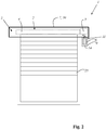
- Figure 2 shows the first embodiment, wherein the second housing 9 is fixed to the bracket 11 and wherein an electrical connection between the first electrical connector 8 and the second electrical connector 10 is made.
- Figure 3 shows a detailed view of a second exemplary embodiment of an actuation system 1 according to the invention for motorized actuation of a blackout device.
- the first electrical connector 8 is constructed in several parts and has an intermediate connector 27.
- the intermediate connector 27 has a first intermediate connector 16 and a second connector 17, which are connected to one another by means of a line 18 running through the tube 15.
- the second adapter plug connector 17 is inserted into a further connector 19, which is designed as a socket and is carried by the housing 7.
- the holder 11 has an intermediate connector holding section 20 which fixes the pipe 15 and in this way mechanically relieves the plug connection between the further connector 19 and the second intermediate connector 17.
- the second housing 9 is mechanically fixed to the holder 11 by executing a locking movement 12, in particular by engaging.
- the holder 11 is designed and arranged in such a way that an automatic connection between the first electrical connector 8, namely the first intermediate connector 16 and the second connector 10, is automatically and inevitably produced by executing the fixing movement 12.
- Figure 4 shows the detailed view of the second exemplary embodiment after the fixing movement 12 has been carried out.
- FIGs 5 and 6 show, as a third exemplary embodiment, an actuation system 1 for the motorized actuation of a closure device 2, namely a window, for opening a wall 21.
- Figure 5 also shows a right-hinged window sash 22, which can be moved into a ventilation position by motor.
- the closure device 2 has an electric drive 5, which actuates a plunger 23, by means of which the window sash 22 can be pushed away from the frame 24 for opening.
- the electric drive 5 is arranged in a first housing 7, which carries a first electrical connector 8.
- a bracket 11 for an intermediate connector 27 of the first connector 8 and for the second housing 9 is attached to the window sash 22.
- the first electrical connector 8 is constructed in several parts and has an intermediate connector 27.
- the intermediate connector 27 has a first intermediate connector 16 and a second connector 17, which are connected to one another by means of a line 18 running through the tube 15.
- the second adapter plug connector 17 is inserted into a further connector 19, which is designed as a socket and is carried by the housing 7.
- the holder 11 has an intermediate connector holding section 20 which fixes the pipe 15 and in this way mechanically relieves the plug connection between the further connector 19 and the second intermediate connector 17.
- the second housing 9 is mechanically fixed to the holder 11 by executing a locking movement 12, in particular by engaging.
- the holder 11 is designed and arranged in such a way that an automatic connection between the first electrical connector 8, namely the first intermediate connector 16 and the second connector 10, is automatically and inevitably produced by executing the fixing movement 12.
- the window has an actuation handle 26.
- FIG. 7 shows a perspective view of a fourth embodiment of an actuation system 1 according to the invention for motorized actuation of a closure device 2 for an opening of a wall 21, namely a window.
- the window has a window wing 22 hinged to the right, which can be moved into a ventilation position by a motor.
- the closure device 2 has an electric drive 5 (not shown in this figure) which actuates a tappet 23 by means of which the window sash 22 can be pushed away from the frame 24 for opening.
- the ventilation position of the window is shown.
- the window sash 22 is again applied to the frame 24 by means of the motor drive 5 via the tappet 23.
- the electric drive 5 is arranged in a first housing 7, which carries a first electrical connector 8.
- a holder 11 (not shown in this figure) is attached, on which a second housing 9 is detachably fixed again.
- the first electrical connector 8 (not shown in this figure) is constructed in several parts and has an intermediate connector 27.
- the intermediate connector 27 is inserted into the second connector 10, which is carried by the second housing 9.
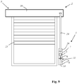
- Fig. 8 shows a fifth embodiment of an actuation system 1 according to the invention for motorized actuation of a blackout device 2.
- the blackout device 2 has a roller shutter 3, a roller shutter armor 25 and a winding roller 4 (not shown in this figure) and a belt winder 28, which has a first housing and which operates the winding roll via a webbing 29.
- the belt winder 28 of the actuation system 1 has an electric drive 5.
- the actuation system 1 also has an electrical energy store 6, in which energy for operating the electric drive 5 is stored or can be stored.
- the belt winder 28 of the actuation system 1 has the first housing 7, which contains the electrical drive 5, but not the electrical energy store 6.
- the first housing 7 carries a first electrical connector 8, which is electrically connected to the electrical drive 5.
- the actuation system 1 also has a second housing 9 which contains the energy store 6 and which carries a second connector 10 which is electrically connected to the electrical energy store 6.
- the actuation system 1 also has a holder 11 which is arranged outside the first housing 7 and on which the second housing 9 can be mechanically fixed by executing a locking movement.
- the holder 11 is designed and arranged such that an electrical connection between the first electrical connector 8 and the second electrical connector 10 is automatically and inevitably produced by executing the fixing movement 12.
- the actuation system 1 has a guide which defines the path of the locking movement 12.
- the guide is designed as a linear guide, the guide having a first guide element 13 and a second guide element 14.
- the first guide element 13 is part of the holder 11, while the second guide element 14 (shown in dashed lines) is part of the second housing 9.
- the guide can be designed, for example, as a dovetail guide.
- the bracket 11 is a separate component from the first housing 7, which is attached separately, for example by means of fastening screws, to the wall.
- Figure 9 shows the fifth embodiment, wherein the second housing 9 is fixed to the bracket 11 and wherein an electrical connection between the first electrical connector 8 and the second electrical connector 10 is made.
- Fig. 10 shows a sixth embodiment of an actuation system 1 according to the invention for the motorized actuation of a blackout device 2, namely a roller blind 31, which has a roller blind 32 and a winding roll 4.
- the winding roll 4 is driven for rotation by means of a ball chain 33.
- a gear 34 is provided with a (not shown) first ball chain wheel, around which the ball chain 4 is placed and in which the individual balls engage.
- the transmission translates a pulling movement of the ball chain into a rotational movement of the winding roller 4 coupled to it.
- the actuation system 11 has an electrical drive 5 for rotating the winding roll 4 and an electrical energy store 6 in which energy for operating the electrical drive 5 is stored or can be stored.
- the electric drive 5 drives a second ball chain wheel 35 for rotation, around which the ball chain 4 is placed and in which the individual balls engage.
- the actuation system 1 also has a first housing 7, which contains the electrical drive 5 and the second ball chain wheel 35, but not the electrical energy store 6.
- the first housing 7 is attached to the wall, preferably screwed on.
- the first housing 7 carries a first electrical connector 8, which is electrically connected to the electrical drive 5.
- the actuation system 1 also has a second housing 9 which contains the energy store 6 and which carries a second connector 10 which is electrically connected to the electrical energy store 6.
- the actuation system 1 also has a holder 11 which is arranged outside the first housing 7 and on which the second housing 9 can be mechanically fixed by executing a locking movement.
- the holder 11 is designed and arranged such that an electrical connection between the first electrical connector 8 and the second electrical connector 10 is automatically and inevitably produced by executing the fixing movement 12.
- the actuation system 1 has a guide which defines the path of the locking movement 12.
- the guide is designed as a linear guide, the guide having a first guide element 13 and a second guide element 14.
- the first guide element 13 is part of the holder 11, while the second guide element 14 (shown in dashed lines) is part of the second housing 9.
- the guide can be designed, for example, as a dovetail guide.
- the holder 11 is a separate component from the first housing 7, which is attached to the wall separately, in particular separately and independently of the first housing 7, for example by means of fastening screws.
- Figure 11 shows the sixth embodiment, wherein the second housing 9 is fixed to the bracket 11 and wherein an electrical connection between the first electrical connector 8 and the second electrical connector 10 is made.
- Fig. 12 shows a seventh embodiment of an actuation system 1 according to the invention for motorized actuation of a blackout device 2, namely an awning 36 which has an awning fabric 37 that can be rolled up and a winding roll 4.
- the winding roll 4 is driven for rotation by means of an awning drive 38 which is coupled via a universal joint 40 and which contains an electric drive 5.
- a deflection gear 39 is present, which transmits a rotational movement of the rotary drive 38 to the winding roll 4.
- the actuation system 11 has an electrical energy store 6, in which energy for operating the electric drive 5 is stored or can be stored.
- the actuation system 1 also has a first housing 7 which contains the electrical drive 5, but not the electrical energy store 6.
- the first housing 7 is attached to the wall, preferably screwed on.
- the first housing 7 carries a first electrical connector 8, which is electrically connected to the electrical drive 5.
- the actuation system 1 also has a second housing 9 which contains the energy store 6 and which carries a second connector 10 which is electrically connected to the electrical energy store 6.
- the actuation system 1 also has a holder 11 arranged outside the first housing 7, on which the second housing 9 by executing a locking movement is mechanically fixable.
- the holder 11 is designed and arranged such that an electrical connection between the first electrical connector 8 and the second electrical connector 10 is automatically and inevitably produced by executing the fixing movement 12.
- the actuation system 1 has a guide which defines the path of the locking movement 12.
- the guide is designed as a linear guide, the guide having a first guide element 13 and a second guide element 14.
- the first guide element 13 is part of the holder 11, while the second guide element 14 (shown in dashed lines) is part of the second housing 9.
- the guide can be designed, for example, as a dovetail guide.
- the bracket 11 is a separate component from the first housing 7, which is attached to the wall separately, in particular separately and independently of the first housing 7, for example by means of fastening screws.
- Figure 13 shows the seventh embodiment, wherein the second housing 9 is fixed to the bracket 11 and wherein an electrical connection between the first electrical connector 8 and the second electrical connector 10 is made.
Landscapes
- Engineering & Computer Science (AREA)
- Structural Engineering (AREA)
- Architecture (AREA)
- Civil Engineering (AREA)
- Operating, Guiding And Securing Of Roll- Type Closing Members (AREA)
- Power-Operated Mechanisms For Wings (AREA)
Applications Claiming Priority (1)
| Application Number | Priority Date | Filing Date | Title |
|---|---|---|---|
| LU101068A LU101068B1 (de) | 2018-12-20 | 2018-12-20 | Betätigungssystem zum motorischen Betätigen einer Verschlussvorrichtung für eine Öffnung einer Wand oder zum Betätigen einer Verdunklungsvorrichtung |
Publications (2)
| Publication Number | Publication Date |
|---|---|
| EP3670815A1 true EP3670815A1 (fr) | 2020-06-24 |
| EP3670815B1 EP3670815B1 (fr) | 2022-03-30 |
Family
ID=65802137
Family Applications (1)
| Application Number | Title | Priority Date | Filing Date |
|---|---|---|---|
| EP19215616.4A Active EP3670815B1 (fr) | 2018-12-20 | 2019-12-12 | Système d'actionnement destiné à l'actionnement motorisé d'un dispositif de verrouillage pour une ouverture d'un mur ou d'actionnement d'un dispositif d'obscurcissement |
Country Status (4)
| Country | Link |
|---|---|
| EP (1) | EP3670815B1 (fr) |
| DE (1) | DE202019005694U1 (fr) |
| ES (1) | ES2917223T3 (fr) |
| LU (1) | LU101068B1 (fr) |
Citations (4)
| Publication number | Priority date | Publication date | Assignee | Title |
|---|---|---|---|---|
| CH684427A5 (de) | 1991-12-18 | 1994-09-15 | Manfred Gruber | Vorrichtung zum motorischen Antrieb von Rolläden und Jalousien. |
| DE60201191T2 (de) | 2001-06-20 | 2005-09-22 | Somfy | Leistungsversorgung für motorisch angetriebene markise oder dergleichen |
| EP2597245A1 (fr) | 2011-11-28 | 2013-05-29 | VKR Holding A/S | Éléments d'appareil pour fenêtre comprenant un écran |
| DE202016105745U1 (de) | 2016-10-13 | 2016-11-03 | heicko e-ast GmbH | Rollladenantriebssystem und Durchführung für Rollladenantriebssystem |
-
2018
- 2018-12-20 LU LU101068A patent/LU101068B1/de active IP Right Grant
-
2019
- 2019-12-12 EP EP19215616.4A patent/EP3670815B1/fr active Active
- 2019-12-12 DE DE202019005694.7U patent/DE202019005694U1/de active Active
- 2019-12-12 ES ES19215616T patent/ES2917223T3/es active Active
Patent Citations (4)
| Publication number | Priority date | Publication date | Assignee | Title |
|---|---|---|---|---|
| CH684427A5 (de) | 1991-12-18 | 1994-09-15 | Manfred Gruber | Vorrichtung zum motorischen Antrieb von Rolläden und Jalousien. |
| DE60201191T2 (de) | 2001-06-20 | 2005-09-22 | Somfy | Leistungsversorgung für motorisch angetriebene markise oder dergleichen |
| EP2597245A1 (fr) | 2011-11-28 | 2013-05-29 | VKR Holding A/S | Éléments d'appareil pour fenêtre comprenant un écran |
| DE202016105745U1 (de) | 2016-10-13 | 2016-11-03 | heicko e-ast GmbH | Rollladenantriebssystem und Durchführung für Rollladenantriebssystem |
Also Published As
| Publication number | Publication date |
|---|---|
| LU101068B1 (de) | 2020-06-24 |
| EP3670815B1 (fr) | 2022-03-30 |
| DE202019005694U1 (de) | 2021-07-01 |
| ES2917223T3 (es) | 2022-07-07 |
Similar Documents
| Publication | Publication Date | Title |
|---|---|---|
| DE69807438T2 (de) | Universelle befestigungs- und parallelführungsvorrichtung für eine fensterabschirmung | |
| DE3214235A1 (de) | Verdunkelungsvorrichtung | |
| EP0298217A1 (fr) | Unité de commande pour store à lamelles ou similaires | |
| EP0448087A1 (fr) | Commande électronique pour volet roulant avec un dispositif de commande à brancher en directe | |
| EP3460155A1 (fr) | Dispositif d'actionnement au moins partiellement automatique d'un vantail de porte | |
| DE10040954A1 (de) | Türmodul für Kraftfahrzeugtüren | |
| DE19949453A1 (de) | Automatische Tür- oder Fensteranlage | |
| DE19840831B4 (de) | Tragbare Aufrollanordnung mit Eigenantrieb für Kabel oder Schläuche | |
| DE102015117706B4 (de) | Antriebsvorrichtung zum Antreiben eines Rollladens | |
| EP3670815B1 (fr) | Système d'actionnement destiné à l'actionnement motorisé d'un dispositif de verrouillage pour une ouverture d'un mur ou d'actionnement d'un dispositif d'obscurcissement | |
| DE102004012354B4 (de) | Elektrischer Gurtwickler | |
| EP0725204A2 (fr) | Dispositif de commande électrique pour une sangle d'un volet à rouleau ou des choses pareilles | |
| AT410354B (de) | Elektrische antriebsvorrichtung für verdunkelungs- oder beschattungsvorrichtung | |
| CH684427A5 (de) | Vorrichtung zum motorischen Antrieb von Rolläden und Jalousien. | |
| DE102015117707A1 (de) | Antriebsvorrichtung zum Antreiben einer Verdunklungsvorrichtung, insbesondere eines Rollladens oder einer Jalousie | |
| DE102010022700B3 (de) | Vorrichtung und Verfahren zur Herstellung einer elektrischen Verbindung zwischen zwei durch ein Scharnier verbundenen Bauteilen | |
| EP3940184B1 (fr) | Dispositif de fermeture pour un caisson d'occultation ou d'ombrage | |
| EP3483374B1 (fr) | Rail de guidage permettant le guidage d'un battant de porte entre une position d'ouverture et une position de fermeture | |
| DE102015017190B4 (de) | Antriebsvorrichtung zum Antreiben eines Rollladens | |
| EP2263292B1 (fr) | Dispositif de décharge de traction | |
| DE202012001209U1 (de) | Betätigungsvorrichtung für ein Fenster oder eine Tür | |
| DE19755818C1 (de) | Sicherung für auf Fahrzeugdächern lösbar anbringbare elektrische Verbraucher | |
| EP3406839A1 (fr) | Unité d'obturation à changement de moteur simplifié | |
| DE102024128105A1 (de) | Steuereinrichtung für einen Antrieb, Verdunklungsvorrichtungsanordnung sowie Verfahren zum Austausch eines Akkus einer Steuereinrichtung | |
| DE102019124389B4 (de) | Vorhangsystem und Verfahren zum Betreiben des Vorhangsystems |
Legal Events
| Date | Code | Title | Description |
|---|---|---|---|
| REG | Reference to a national code |
Ref country code: DE Ref legal event code: R138 Ref document number: 202019005694 Country of ref document: DE Free format text: GERMAN DOCUMENT NUMBER IS 502019003858 |
|
| PUAI | Public reference made under article 153(3) epc to a published international application that has entered the european phase |
Free format text: ORIGINAL CODE: 0009012 |
|
| STAA | Information on the status of an ep patent application or granted ep patent |
Free format text: STATUS: THE APPLICATION HAS BEEN PUBLISHED |
|
| AK | Designated contracting states |
Kind code of ref document: A1 Designated state(s): AL AT BE BG CH CY CZ DE DK EE ES FI FR GB GR HR HU IE IS IT LI LT LU LV MC MK MT NL NO PL PT RO RS SE SI SK SM TR |
|
| AX | Request for extension of the european patent |
Extension state: BA ME |
|
| STAA | Information on the status of an ep patent application or granted ep patent |
Free format text: STATUS: REQUEST FOR EXAMINATION WAS MADE |
|
| 17P | Request for examination filed |
Effective date: 20200914 |
|
| RBV | Designated contracting states (corrected) |
Designated state(s): AL AT BE BG CH CY CZ DE DK EE ES FI FR GB GR HR HU IE IS IT LI LT LU LV MC MK MT NL NO PL PT RO RS SE SI SK SM TR |
|
| GRAP | Despatch of communication of intention to grant a patent |
Free format text: ORIGINAL CODE: EPIDOSNIGR1 |
|
| STAA | Information on the status of an ep patent application or granted ep patent |
Free format text: STATUS: GRANT OF PATENT IS INTENDED |
|
| INTG | Intention to grant announced |
Effective date: 20211020 |
|
| GRAS | Grant fee paid |
Free format text: ORIGINAL CODE: EPIDOSNIGR3 |
|
| GRAA | (expected) grant |
Free format text: ORIGINAL CODE: 0009210 |
|
| STAA | Information on the status of an ep patent application or granted ep patent |
Free format text: STATUS: THE PATENT HAS BEEN GRANTED |
|
| AK | Designated contracting states |
Kind code of ref document: B1 Designated state(s): AL AT BE BG CH CY CZ DE DK EE ES FI FR GB GR HR HU IE IS IT LI LT LU LV MC MK MT NL NO PL PT RO RS SE SI SK SM TR |
|
| REG | Reference to a national code |
Ref country code: GB Ref legal event code: FG4D Free format text: NOT ENGLISH |
|
| REG | Reference to a national code |
Ref country code: CH Ref legal event code: EP |
|
| REG | Reference to a national code |
Ref country code: AT Ref legal event code: REF Ref document number: 1479346 Country of ref document: AT Kind code of ref document: T Effective date: 20220415 |
|
| REG | Reference to a national code |
Ref country code: DE Ref legal event code: R096 Ref document number: 502019003858 Country of ref document: DE |
|
| REG | Reference to a national code |
Ref country code: IE Ref legal event code: FG4D Free format text: LANGUAGE OF EP DOCUMENT: GERMAN |
|
| REG | Reference to a national code |
Ref country code: ES Ref legal event code: FG2A Ref document number: 2917223 Country of ref document: ES Kind code of ref document: T3 Effective date: 20220707 |
|
| REG | Reference to a national code |
Ref country code: LT Ref legal event code: MG9D |
|
| PG25 | Lapsed in a contracting state [announced via postgrant information from national office to epo] |
Ref country code: SE Free format text: LAPSE BECAUSE OF FAILURE TO SUBMIT A TRANSLATION OF THE DESCRIPTION OR TO PAY THE FEE WITHIN THE PRESCRIBED TIME-LIMIT Effective date: 20220330 Ref country code: RS Free format text: LAPSE BECAUSE OF FAILURE TO SUBMIT A TRANSLATION OF THE DESCRIPTION OR TO PAY THE FEE WITHIN THE PRESCRIBED TIME-LIMIT Effective date: 20220330 Ref country code: NO Free format text: LAPSE BECAUSE OF FAILURE TO SUBMIT A TRANSLATION OF THE DESCRIPTION OR TO PAY THE FEE WITHIN THE PRESCRIBED TIME-LIMIT Effective date: 20220630 Ref country code: LT Free format text: LAPSE BECAUSE OF FAILURE TO SUBMIT A TRANSLATION OF THE DESCRIPTION OR TO PAY THE FEE WITHIN THE PRESCRIBED TIME-LIMIT Effective date: 20220330 Ref country code: HR Free format text: LAPSE BECAUSE OF FAILURE TO SUBMIT A TRANSLATION OF THE DESCRIPTION OR TO PAY THE FEE WITHIN THE PRESCRIBED TIME-LIMIT Effective date: 20220330 Ref country code: BG Free format text: LAPSE BECAUSE OF FAILURE TO SUBMIT A TRANSLATION OF THE DESCRIPTION OR TO PAY THE FEE WITHIN THE PRESCRIBED TIME-LIMIT Effective date: 20220630 |
|
| REG | Reference to a national code |
Ref country code: NL Ref legal event code: MP Effective date: 20220330 |
|
| PG25 | Lapsed in a contracting state [announced via postgrant information from national office to epo] |
Ref country code: LV Free format text: LAPSE BECAUSE OF FAILURE TO SUBMIT A TRANSLATION OF THE DESCRIPTION OR TO PAY THE FEE WITHIN THE PRESCRIBED TIME-LIMIT Effective date: 20220330 Ref country code: GR Free format text: LAPSE BECAUSE OF FAILURE TO SUBMIT A TRANSLATION OF THE DESCRIPTION OR TO PAY THE FEE WITHIN THE PRESCRIBED TIME-LIMIT Effective date: 20220701 Ref country code: FI Free format text: LAPSE BECAUSE OF FAILURE TO SUBMIT A TRANSLATION OF THE DESCRIPTION OR TO PAY THE FEE WITHIN THE PRESCRIBED TIME-LIMIT Effective date: 20220330 |
|
| PG25 | Lapsed in a contracting state [announced via postgrant information from national office to epo] |
Ref country code: NL Free format text: LAPSE BECAUSE OF FAILURE TO SUBMIT A TRANSLATION OF THE DESCRIPTION OR TO PAY THE FEE WITHIN THE PRESCRIBED TIME-LIMIT Effective date: 20220330 |
|
| PG25 | Lapsed in a contracting state [announced via postgrant information from national office to epo] |
Ref country code: SM Free format text: LAPSE BECAUSE OF FAILURE TO SUBMIT A TRANSLATION OF THE DESCRIPTION OR TO PAY THE FEE WITHIN THE PRESCRIBED TIME-LIMIT Effective date: 20220330 Ref country code: SK Free format text: LAPSE BECAUSE OF FAILURE TO SUBMIT A TRANSLATION OF THE DESCRIPTION OR TO PAY THE FEE WITHIN THE PRESCRIBED TIME-LIMIT Effective date: 20220330 Ref country code: RO Free format text: LAPSE BECAUSE OF FAILURE TO SUBMIT A TRANSLATION OF THE DESCRIPTION OR TO PAY THE FEE WITHIN THE PRESCRIBED TIME-LIMIT Effective date: 20220330 Ref country code: PT Free format text: LAPSE BECAUSE OF FAILURE TO SUBMIT A TRANSLATION OF THE DESCRIPTION OR TO PAY THE FEE WITHIN THE PRESCRIBED TIME-LIMIT Effective date: 20220801 Ref country code: EE Free format text: LAPSE BECAUSE OF FAILURE TO SUBMIT A TRANSLATION OF THE DESCRIPTION OR TO PAY THE FEE WITHIN THE PRESCRIBED TIME-LIMIT Effective date: 20220330 Ref country code: CZ Free format text: LAPSE BECAUSE OF FAILURE TO SUBMIT A TRANSLATION OF THE DESCRIPTION OR TO PAY THE FEE WITHIN THE PRESCRIBED TIME-LIMIT Effective date: 20220330 |
|
| PG25 | Lapsed in a contracting state [announced via postgrant information from national office to epo] |
Ref country code: PL Free format text: LAPSE BECAUSE OF FAILURE TO SUBMIT A TRANSLATION OF THE DESCRIPTION OR TO PAY THE FEE WITHIN THE PRESCRIBED TIME-LIMIT Effective date: 20220330 Ref country code: IS Free format text: LAPSE BECAUSE OF FAILURE TO SUBMIT A TRANSLATION OF THE DESCRIPTION OR TO PAY THE FEE WITHIN THE PRESCRIBED TIME-LIMIT Effective date: 20220730 Ref country code: AL Free format text: LAPSE BECAUSE OF FAILURE TO SUBMIT A TRANSLATION OF THE DESCRIPTION OR TO PAY THE FEE WITHIN THE PRESCRIBED TIME-LIMIT Effective date: 20220330 |
|
| REG | Reference to a national code |
Ref country code: DE Ref legal event code: R097 Ref document number: 502019003858 Country of ref document: DE |
|
| PG25 | Lapsed in a contracting state [announced via postgrant information from national office to epo] |
Ref country code: DK Free format text: LAPSE BECAUSE OF FAILURE TO SUBMIT A TRANSLATION OF THE DESCRIPTION OR TO PAY THE FEE WITHIN THE PRESCRIBED TIME-LIMIT Effective date: 20220330 |
|
| PGFP | Annual fee paid to national office [announced via postgrant information from national office to epo] |
Ref country code: FR Payment date: 20221216 Year of fee payment: 4 Ref country code: DE Payment date: 20221209 Year of fee payment: 4 |
|
| PLBE | No opposition filed within time limit |
Free format text: ORIGINAL CODE: 0009261 |
|
| STAA | Information on the status of an ep patent application or granted ep patent |
Free format text: STATUS: NO OPPOSITION FILED WITHIN TIME LIMIT |
|
| 26N | No opposition filed |
Effective date: 20230103 |
|
| PGFP | Annual fee paid to national office [announced via postgrant information from national office to epo] |
Ref country code: ES Payment date: 20230102 Year of fee payment: 4 |
|
| PG25 | Lapsed in a contracting state [announced via postgrant information from national office to epo] |
Ref country code: SI Free format text: LAPSE BECAUSE OF FAILURE TO SUBMIT A TRANSLATION OF THE DESCRIPTION OR TO PAY THE FEE WITHIN THE PRESCRIBED TIME-LIMIT Effective date: 20220330 |
|
| PGFP | Annual fee paid to national office [announced via postgrant information from national office to epo] |
Ref country code: IT Payment date: 20221231 Year of fee payment: 4 |
|
| REG | Reference to a national code |
Ref country code: CH Ref legal event code: PL |
|
| REG | Reference to a national code |
Ref country code: BE Ref legal event code: MM Effective date: 20221231 |
|
| PG25 | Lapsed in a contracting state [announced via postgrant information from national office to epo] |
Ref country code: LU Free format text: LAPSE BECAUSE OF NON-PAYMENT OF DUE FEES Effective date: 20221212 |
|
| PG25 | Lapsed in a contracting state [announced via postgrant information from national office to epo] |
Ref country code: LI Free format text: LAPSE BECAUSE OF NON-PAYMENT OF DUE FEES Effective date: 20221231 Ref country code: IE Free format text: LAPSE BECAUSE OF NON-PAYMENT OF DUE FEES Effective date: 20221212 Ref country code: CH Free format text: LAPSE BECAUSE OF NON-PAYMENT OF DUE FEES Effective date: 20221231 |
|
| PG25 | Lapsed in a contracting state [announced via postgrant information from national office to epo] |
Ref country code: BE Free format text: LAPSE BECAUSE OF NON-PAYMENT OF DUE FEES Effective date: 20221231 |
|
| PG25 | Lapsed in a contracting state [announced via postgrant information from national office to epo] |
Ref country code: HU Free format text: LAPSE BECAUSE OF FAILURE TO SUBMIT A TRANSLATION OF THE DESCRIPTION OR TO PAY THE FEE WITHIN THE PRESCRIBED TIME-LIMIT; INVALID AB INITIO Effective date: 20191212 |
|
| PG25 | Lapsed in a contracting state [announced via postgrant information from national office to epo] |
Ref country code: CY Free format text: LAPSE BECAUSE OF FAILURE TO SUBMIT A TRANSLATION OF THE DESCRIPTION OR TO PAY THE FEE WITHIN THE PRESCRIBED TIME-LIMIT Effective date: 20220330 |
|
| PG25 | Lapsed in a contracting state [announced via postgrant information from national office to epo] |
Ref country code: MK Free format text: LAPSE BECAUSE OF FAILURE TO SUBMIT A TRANSLATION OF THE DESCRIPTION OR TO PAY THE FEE WITHIN THE PRESCRIBED TIME-LIMIT Effective date: 20220330 |
|
| PG25 | Lapsed in a contracting state [announced via postgrant information from national office to epo] |
Ref country code: MC Free format text: LAPSE BECAUSE OF FAILURE TO SUBMIT A TRANSLATION OF THE DESCRIPTION OR TO PAY THE FEE WITHIN THE PRESCRIBED TIME-LIMIT Effective date: 20220330 |
|
| PG25 | Lapsed in a contracting state [announced via postgrant information from national office to epo] |
Ref country code: MC Free format text: LAPSE BECAUSE OF FAILURE TO SUBMIT A TRANSLATION OF THE DESCRIPTION OR TO PAY THE FEE WITHIN THE PRESCRIBED TIME-LIMIT Effective date: 20220330 |
|
| REG | Reference to a national code |
Ref country code: DE Ref legal event code: R119 Ref document number: 502019003858 Country of ref document: DE |
|
| GBPC | Gb: european patent ceased through non-payment of renewal fee |
Effective date: 20231212 |
|
| PG25 | Lapsed in a contracting state [announced via postgrant information from national office to epo] |
Ref country code: MT Free format text: LAPSE BECAUSE OF FAILURE TO SUBMIT A TRANSLATION OF THE DESCRIPTION OR TO PAY THE FEE WITHIN THE PRESCRIBED TIME-LIMIT Effective date: 20220330 |
|
| PG25 | Lapsed in a contracting state [announced via postgrant information from national office to epo] |
Ref country code: DE Free format text: LAPSE BECAUSE OF NON-PAYMENT OF DUE FEES Effective date: 20240702 |
|
| PG25 | Lapsed in a contracting state [announced via postgrant information from national office to epo] |
Ref country code: GB Free format text: LAPSE BECAUSE OF NON-PAYMENT OF DUE FEES Effective date: 20231212 |
|
| PG25 | Lapsed in a contracting state [announced via postgrant information from national office to epo] |
Ref country code: FR Free format text: LAPSE BECAUSE OF NON-PAYMENT OF DUE FEES Effective date: 20231231 |
|
| PG25 | Lapsed in a contracting state [announced via postgrant information from national office to epo] |
Ref country code: GB Free format text: LAPSE BECAUSE OF NON-PAYMENT OF DUE FEES Effective date: 20231212 Ref country code: FR Free format text: LAPSE BECAUSE OF NON-PAYMENT OF DUE FEES Effective date: 20231231 Ref country code: DE Free format text: LAPSE BECAUSE OF NON-PAYMENT OF DUE FEES Effective date: 20240702 |
|
| REG | Reference to a national code |
Ref country code: ES Ref legal event code: FD2A Effective date: 20250127 |
|
| PG25 | Lapsed in a contracting state [announced via postgrant information from national office to epo] |
Ref country code: ES Free format text: LAPSE BECAUSE OF NON-PAYMENT OF DUE FEES Effective date: 20231213 |
|
| PG25 | Lapsed in a contracting state [announced via postgrant information from national office to epo] |
Ref country code: TR Free format text: LAPSE BECAUSE OF FAILURE TO SUBMIT A TRANSLATION OF THE DESCRIPTION OR TO PAY THE FEE WITHIN THE PRESCRIBED TIME-LIMIT Effective date: 20220330 |
|
| REG | Reference to a national code |
Ref country code: AT Ref legal event code: MM01 Ref document number: 1479346 Country of ref document: AT Kind code of ref document: T Effective date: 20241212 |
|
| PG25 | Lapsed in a contracting state [announced via postgrant information from national office to epo] |
Ref country code: AT Free format text: LAPSE BECAUSE OF NON-PAYMENT OF DUE FEES Effective date: 20241212 |
|
| PGFP | Annual fee paid to national office [announced via postgrant information from national office to epo] |
Ref country code: AT Payment date: 20260410 Year of fee payment: 5 |