EP3670992A1 - Anschlussbuchse und fluidanschluss, der ein steckanschlusselement sowie diese anschlussbuchse umfasst - Google Patents
Anschlussbuchse und fluidanschluss, der ein steckanschlusselement sowie diese anschlussbuchse umfasst Download PDFInfo
- Publication number
- EP3670992A1 EP3670992A1 EP19218661.7A EP19218661A EP3670992A1 EP 3670992 A1 EP3670992 A1 EP 3670992A1 EP 19218661 A EP19218661 A EP 19218661A EP 3670992 A1 EP3670992 A1 EP 3670992A1
- Authority
- EP
- European Patent Office
- Prior art keywords
- female
- connector element
- ring
- longitudinal axis
- male
- Prior art date
- Legal status (The legal status is an assumption and is not a legal conclusion. Google has not performed a legal analysis and makes no representation as to the accuracy of the status listed.)
- Granted
Links
Images


Classifications
-
- F—MECHANICAL ENGINEERING; LIGHTING; HEATING; WEAPONS; BLASTING
- F16—ENGINEERING ELEMENTS AND UNITS; GENERAL MEASURES FOR PRODUCING AND MAINTAINING EFFECTIVE FUNCTIONING OF MACHINES OR INSTALLATIONS; THERMAL INSULATION IN GENERAL
- F16L—PIPES; JOINTS OR FITTINGS FOR PIPES; SUPPORTS FOR PIPES, CABLES OR PROTECTIVE TUBING; MEANS FOR THERMAL INSULATION IN GENERAL
- F16L37/00—Couplings of the quick-acting type
- F16L37/08—Couplings of the quick-acting type in which the connection between abutting or axially overlapping ends is maintained by locking members
- F16L37/12—Couplings of the quick-acting type in which the connection between abutting or axially overlapping ends is maintained by locking members using hooks, pawls, or other movable or insertable locking members
- F16L37/1225—Couplings of the quick-acting type in which the connection between abutting or axially overlapping ends is maintained by locking members using hooks, pawls, or other movable or insertable locking members using a retaining member the extremities of which, e.g. in the form of a U, engage behind a shoulder of both parts
-
- F—MECHANICAL ENGINEERING; LIGHTING; HEATING; WEAPONS; BLASTING
- F16—ENGINEERING ELEMENTS AND UNITS; GENERAL MEASURES FOR PRODUCING AND MAINTAINING EFFECTIVE FUNCTIONING OF MACHINES OR INSTALLATIONS; THERMAL INSULATION IN GENERAL
- F16L—PIPES; JOINTS OR FITTINGS FOR PIPES; SUPPORTS FOR PIPES, CABLES OR PROTECTIVE TUBING; MEANS FOR THERMAL INSULATION IN GENERAL
- F16L37/00—Couplings of the quick-acting type
- F16L37/08—Couplings of the quick-acting type in which the connection between abutting or axially overlapping ends is maintained by locking members
- F16L37/084—Couplings of the quick-acting type in which the connection between abutting or axially overlapping ends is maintained by locking members combined with automatic locking
- F16L37/0841—Couplings of the quick-acting type in which the connection between abutting or axially overlapping ends is maintained by locking members combined with automatic locking by means of a transversally slidable locking member surrounding the tube
-
- F—MECHANICAL ENGINEERING; LIGHTING; HEATING; WEAPONS; BLASTING
- F16—ENGINEERING ELEMENTS AND UNITS; GENERAL MEASURES FOR PRODUCING AND MAINTAINING EFFECTIVE FUNCTIONING OF MACHINES OR INSTALLATIONS; THERMAL INSULATION IN GENERAL
- F16L—PIPES; JOINTS OR FITTINGS FOR PIPES; SUPPORTS FOR PIPES, CABLES OR PROTECTIVE TUBING; MEANS FOR THERMAL INSULATION IN GENERAL
- F16L37/00—Couplings of the quick-acting type
- F16L37/22—Couplings of the quick-acting type in which the connection is maintained by means of balls, rollers or helical springs under radial pressure between the parts
- F16L37/23—Couplings of the quick-acting type in which the connection is maintained by means of balls, rollers or helical springs under radial pressure between the parts by means of balls
-
- F—MECHANICAL ENGINEERING; LIGHTING; HEATING; WEAPONS; BLASTING
- F16—ENGINEERING ELEMENTS AND UNITS; GENERAL MEASURES FOR PRODUCING AND MAINTAINING EFFECTIVE FUNCTIONING OF MACHINES OR INSTALLATIONS; THERMAL INSULATION IN GENERAL
- F16L—PIPES; JOINTS OR FITTINGS FOR PIPES; SUPPORTS FOR PIPES, CABLES OR PROTECTIVE TUBING; MEANS FOR THERMAL INSULATION IN GENERAL
- F16L37/00—Couplings of the quick-acting type
- F16L37/28—Couplings of the quick-acting type with fluid cut-off means
- F16L37/38—Couplings of the quick-acting type with fluid cut-off means with fluid cut-off means in only one of two pipe-end fittings
- F16L37/40—Couplings of the quick-acting type with fluid cut-off means with fluid cut-off means in only one of two pipe-end fittings with a lift valve being opened automatically when the coupling is applied
- F16L37/42—Couplings of the quick-acting type with fluid cut-off means with fluid cut-off means in only one of two pipe-end fittings with a lift valve being opened automatically when the coupling is applied the valve having an axial bore communicating with lateral apertures
Definitions
- the present invention relates to a female fluid connection element, as well as a fluid connection comprising a male connection element as well as said female connection element.
- the invention relates to the field of fluidic connections, in particular for filling tanks with refrigerant, for example up to 20 bars.
- EP 1,916,464 A1 describes a female connector element, capable of receiving a smooth tubular male element in fitting.
- the female element comprises a seal housed inside a body of the female element and able to cooperate in leaktight manner with a peripheral surface of the male element.
- the female element further comprises an interface member, housed inside the body of the female element. The interface member is moved in translation parallel to the fitting axis under the action of the male element, during fitting in the female element, from a first position, in which the member d interface is interposed radially between the seal and the peripheral surface of the male element, towards a second position, in which the interface member is offset axially with respect to the seal, the seal resting tightly on the peripheral surface of the male element.
- the interface member thus prevents degradation of the seal during fitting of the male element, in particular if said male element has irregularities projecting from its peripheral surface.
- the locking of the male element is ensured by balls housed in a movable locking ring, the balls wedging the peripheral surface of the male element.
- the balls are thus held by a surface provided at a mouth of the body.
- the locking of the male element is automatic, since, at coupling, the end of the male element first pushes the balls and the locking ring backwards relative to the body of the female element, to a certain position where a spring pushes the locking ring in the opposite direction, so as to lock the male element in the female element.
- FR 1 487 324 A describes a female connection element, capable of locking a male connection element comprising a frustoconical profile flange.
- this female element comprises a lock, comprising a tooth designed to come into engagement with the flange in the lock retaining position.
- the locking of the male element in the female element is automatic by engagement of the frustoconical profile with this same tooth which moves the lock from its retaining position to its release position in which the lock frees the passage for the male element connection in the female element.
- the lock is held in the male element retaining position by a transverse stud, which the user must push back to allow the male element to be locked and unlocked.
- this known female connector element requires a frustoconical surface on the latch tooth for automatic coupling, which requires that a significant length of the male element be introduced into the female element to achieve coupling.
- An object of the invention is therefore to remedy the drawbacks of the prior art, by proposing a new female element for fluid connection which automatically opposes the withdrawal of a male element fitted within it, even if the element male is of reduced length, in particular even if the external radial surface of the part of the male element fitted into the female element has a longitudinally constant diameter.
- the female element automatically ensures a locking opposing the withdrawal of the male element, when this male element is fitted into the internal channel.
- the fitting movement of the male element pushes the pusher and thus leads the pusher to drive the memory ring to its retracted position.
- the memory ring then authorizes the lock to be automatically brought into the retaining position by the elastic means.
- the pusher and the memory ring being simply actuated by being pushed by the male element, the positioning of the bolt retaining position is carried out even if the male element is of longitudinally constant diameter, that is to say that it does not have a groove, flange or shoulder. So that the male element can push the pusher, it is provided for example that, during the fitting of the male element, a front end of the male element actuates the pusher.
- the invention provides that the lock is radially movable relative to the longitudinal axis in order to reduce the longitudinal dimensions of the female element.
- the lock being longitudinally short, it can advantageously be arranged between a front end of the female element and the pusher. Thus, during fitting into the female element, a male element of reduced length can still reach and actuate the pusher, so that the memory ring is driven to automatically move the latch into the retaining position.
- the lock cooperates with an external radial surface of the male element
- the lock is directly in contact with the external radial surface of the male element. The lock therefore opposes itself to the withdrawal of the male element, without intermediate piece.
- the invention also relates to a fluidic connection, comprising a male connection element, as well as the female connection element as defined above, the male connection element being able to come longitudinally into abutment against the pusher and to push back the pusher from its front position to its rear position, the lock cooperating, in the retaining position, with the external radial surface of the male connection element to oppose the withdrawal of the male connection element from the female body, the external radial surface of the male connection element being of longitudinally constant diameter over its entire longitudinal part fitted into the female connection element in the coupled configuration.
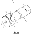
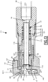
- a fluidic connection 1 comprises a female fluidic connection element 11 and a male fluidic connection element 2.
- the male connector element 2 is a brass or copper tube.
- the male connection element 2 comprises a front end 4.
- the male connection element 2 is preferably tubular, that is to say that it comprises an external radial surface 3 of longitudinally constant diameter along the axis X2, at least for a longitudinal part of the male connection element 2 extending from its front end 4 and intended to be fitted into the female connection element 11.
- the male connection element also comprises a channel internal.
- the tubular shape of the male connector element 2 is advantageously coaxial with the axis X2.
- the male connector element 2 is a copper or brass tube with a circular cross section.
- the internal channel of the male connector element 2 is fluidly connected, at its rear end, to a reservoir of pressurized fluid, for example at 20 bars, for example a refrigerating fluid.
- the male connection element 2 forms an inlet to the reservoir and is used to fill the reservoir with this pressurized fluid, coming from the female connection element 11. Once filling is completed, the male connection element 2 is crushed and welded and the front end 4 is cut.
- the female connector element 11 comprises a female body 21, preferably comprising a front body 22, a rear body 24 and an intermediate body 23, which are tubular and coaxial with the longitudinal axis X11.
- the front body 22 and the rear body 24 are fixedly secured to one another.
- the rear body 24 is designed to be connected to a pipe 99, shown in broken lines on the figure 1 , also coaxial with the longitudinal axis X11.
- the female body 21 delimits an internal channel 29 in communication with the pipe 99.
- the front body 22, the intermediate body 23 and the rear body 24 each delimit, along the longitudinal axis X11, a successive part of the internal channel 29.
- the front body 22 comprises a mouth 25, which extends axially at a front end of the front body 22.
- the internal channel 29 is shaped to receive the male connection element 2 fitting into it.
- the male connector element 2 can be introduced into the internal channel 29, via the front end 4, introduced into the female body 21 via the mouth 25.
- the female connector element 11 is shaped so that the longitudinal axes X2 and X11 of the fluidic connector 1 are coaxial.
- the front body 22 comprises a latch housing 26, which extends radially to the longitudinal axis X11 and which opens onto an external radial surface of the front body 22, in a radial direction relative to the longitudinal axis X11 and which is blind in the opposite radial direction.
- the intermediate body 23 comprises, at its front end, an inclined internal surface 30 at a bevel, which diverges forwards.
- the inclined internal surface 30 is of conical shape centered on the longitudinal axis X11.
- the intermediate body 23 forms an internal radial covering surface 14, of constant diameter along the longitudinal axis X11.
- the female connector element 11 comprises a lock 41 received in the lock housing 26.
- the lock 41 is able to lock the male connector element 2, in particular if the male element is a copper or brass tube.
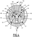
- the lock 41 is slidably mounted in the front body 22, transversely with respect to the longitudinal axis X11, in particular radially with respect to the longitudinal axis X11, between a position for retaining the male connector element 2 in the female body 21, shown on the figures 3 , 7 and 8 , and a release position, shown on the figures 1 , 2 , 4 and 5 , in which the latch 41 does not oppose the withdrawal of the male connection element 2 from the female body 21 or the introduction of the male connection element 2 into the female body 21.
- the lock 41 is preferably more pressed into the female body 21 than in the retaining position.
- the latch 41 allows movement of the male connector element 2 in the female body 21, at least longitudinally.
- a radial axis R11 is defined, which is radial with respect to the longitudinal axis X11.
- the latch 41 is movable along the radial axis R11 relative to the female body 21.
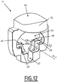
- Lock 41 shown alone on the figure 12 , comprises an actuating part 42, with an external face 43, on which an operator can act.
- the external face 43 is therefore accessible from the outside of the female body 21, in particular from the outside of the lock housing 26 with the actuating part 42 disposed at the level of the radial outlet of the lock housing 26.
- the external face 43 of the lock 41 is further from the longitudinal axis X11 than in the release position.
- the lock 41 also includes an opening 44 which passes longitudinally through the lock 41 and which is intended to receive the male connection element 2.
- the male connection element 2 then passes through the lock 41 via the opening 44.
- This opening 44 delimits two locking surfaces 45a and 45b.
- the locking surfaces 45a, 45b each delimit only a portion of the opening 44 around the axis X11.
- the two locking surfaces 45a and 45b are arranged on either side of the axis X11, preferably symmetrically with respect to a radial plane containing the radial axis R11, for example the section plane of the figure 1 .
- the two locking surfaces 45a and 45b are preferably planar surfaces.
- the two surfaces of locking 45a and 45b are inclined relative to each other, together forming a V-shaped passage, that is to say a flared notch, wider on the front on the side of the mouth 25 than the rear side of the female connector element 11.
- This plane orthoradial to the longitudinal axis X11 is for example the plane of the figure 9 .
- the locking surfaces 45a and 45b advantageously converge towards the rear of the female connector element 11.
- the locking surfaces 45a and 45b preferably form an angle ⁇ of 18 ° (degrees), where each locking surface 45a, 45b forms an angle of 9 ° relative to a longitudinal direction X11 'parallel to the axis longitudinal X11.
- the two locking surfaces 45a and 45b are inclined relative to each other.
- the locking surfaces 45a and 45b are arranged on either side of the radial axis R11.
- the passage of the opening 44 formed by the locking surfaces 45a, 45b is also V-shaped, that is to say that the passage forms a flared notch, the mouth of which is closer of the actuating part 42 that the bottom of the V-shaped passage is wider than the bottom.
- the locking surfaces 45a and 45b converge opposite the actuation part 42 and the radial opening of the housing 26 in which the actuation part 42 is received.
- the locking surfaces 45a and 45b together form an angle ⁇ of 30 °, where each locking surface 45a, 45b forms an angle of 15 ° each with respect to the radial axis R11.
- the opening 44 also delimits two abutment surfaces 46, which are orthoradial to the longitudinal axis X11.
- the two abutment surfaces 46 are perpendicular to the radial axis R11.
- the two abutment surfaces 46 extend in the same plane parallel to the orthoradial plane of the figure 9 or in a plane perpendicular to the plane of the figure 1 .
- the abutment surfaces 46 each extend from one of the locking surfaces 45a, 45b, being symmetrical with respect to a plane comprising the radial axis R11 and the longitudinal axis X11.
- the abutment surfaces 46 are oriented towards the actuating part 42 of the latch 41.
- the latch 41 also delimits two retaining surfaces 39, which are orthoradial to the longitudinal axis X11.
- the retaining surfaces 39 extend in the same plane parallel to the orthoradial plane of the figure 9 .
- the retaining surfaces 39 extend respectively behind each of the abutment surfaces 46, being symmetrical with respect to the plane comprising the radial axis R11 and the longitudinal axis X11.
- An axial surface connects each of the abutment surfaces 46 and the retaining surface 39 which is axially aligned with it.
- the retaining surfaces 39 are more distant from the external face 43 of the latch 41 than the abutment surfaces 46.
- the opening 44 also delimits a longitudinal indexing groove 47, which opens into the V-shaped passage formed by the locking surfaces 45a and 45b.
- the longitudinal indexing groove 47 connects the locking surfaces 45a and 45b together, being crossed by the plane comprising the radial axis R11 and the longitudinal axis X11.
- the female connecting element 11 comprises two helical compression springs 49, which constitute elastic means which push the latch 41 towards its retaining position, bearing on the female body 21.
- the latch 41 advantageously comprises two external transverse housings 48, which extend parallel to the sliding axis of the lock 41, here the radial axis R11.
- the front body 22 advantageously comprises two external transverse housings 27, which extend parallel to the sliding axis of the lock 41, and are arranged opposite the external transverse housings 48.
- Each spring 49 is housed at a transverse end of the spring 49, in one of the external transverse housings 48 and, at an opposite transverse end of the spring 49, in one of the external transverse housings 27.
- the elastic return means being in the form of two springs 49, they thus offer an elastic return force compatible with the locking force desired for the male connection element 2.
- the female connector element 11 comprises a push-button ring 51, which constitutes a preferred example of a push-button.
- the push ring 51 is advantageously of generally tubular shape coaxial with the longitudinal axis X11.
- the push ring 51 is movably mounted inside the intermediate body 23, in the internal channel 29 of the female body 21.
- the push ring 51 slides longitudinally relative to the female body 21 but is radially integral with the female body 21.
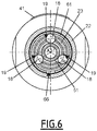
- the intermediate body 23 comprises three elongated housings 19, which each house an actuating ball 18. As shown in the figure 6 , three actuating balls 18, housed in three respective elongated housings 19, are advantageously provided. Each elongated housing 19 passes radially through the intermediate body 23.
- the elongated housings 19 are advantageously distributed regularly around the longitudinal axis X11, all being arranged at the same longitudinal level on the longitudinal axis X11.
- elongated is meant that each elongated housing 19 is elongated in the longitudinal direction. In the orthoradial direction, each elongated housing 19 is preferably of width adjusted to the diameter of the actuating ball 18 that this elongated housing 19 receives.
- the female connector element 11 comprises two auxiliary O-rings 32 and 33, which are housed in two respective internal grooves 16 and 17 of the female body 21.
- the auxiliary seals 32 and 33 as well as the grooves 16 and 17 are advantageously coaxial with the longitudinal axis X11.
- the auxiliary seal 32 and the groove 16 are advantageously provided on the intermediate body 23.
- the auxiliary seal 33 and the groove 17 are advantageously provided on the rear body 24.
- the two auxiliary seals 32 and 33 are arranged longitudinally on either side of the elongated housings 19, the auxiliary seal 32 being disposed at the front, while the auxiliary seal 33 is disposed at the rear.
- the auxiliary seals 32 and 33 are radially interposed between the female body 21 and the pusher 51, in order to ensure sealing between the female body 21 and the pusher 51.
- the auxiliary seals 32 and 33 are designed to ensure the seal between the pusher ring 51 and the female body 21 whatever the longitudinal position of the pusher ring 51 in the female body 21.
- the pusher ring 51 comprises a front collar 52 and a rear collar 53 which delimit, longitudinally between them, a volume 54 for partial reception of the actuating balls 18, the volume 54 advantageously having an annular shape.
- the front flange 52 comprises, at the rear, a contact surface 58 intended to come into contact with the actuating balls 18 during a rearward movement of the pusher ring 51, in order to drive the balls d actuation 18 towards the rear
- the actuation balls 18 therefore cooperate longitudinally with the pusher ring 51.
- the contact surface 58 delimits the volume 54.
- the female connector element 11 also comprises a spring 71, which is longitudinally interposed between the rear body 24 and the push-button ring 51.
- the spring 71 pushes the push-button ring 51 longitudinally towards the mouth 25 of the front body 22, this is that is to say towards a front position of the pusher ring 51 relative to the female body 21.
- the push ring 51 is in the front position.
- the rear flange 53 advantageously provides axial support for the spring 71.
- the push ring 51 defines a front counterbore 55.
- the front counterbore 55 is delimited longitudinally, towards the rear, by a longitudinal shoulder 56 of the push-button ring 51.
- the front counterbore 55 opens, towards the front, outside the push ring 51, at a front end 12 of the push ring 51.
- the female connector element 11 comprises a memory ring 61.
- the memory ring 61 is advantageously of tubular general shape coaxial with the longitudinal axis X11.
- the memory ring 61 is mounted radially between the front body 22 and the intermediate body 23, that is to say that the front body 22 surrounds the memory ring 61, while the memory ring 61 surrounds the intermediate body 23.
- the body front 22 also surrounds the intermediate body 23.
- the pusher ring 51 and the memory ring 61 are arranged radially on either side of the intermediate body 23.
- the memory ring 61 is mounted with the possibility of longitudinal sliding relative to the female body 21, but is radially integral with the female body 21.
- This memory ring 61 comprises an external ring 62 and an annular internal ring 63.
- the annular internal ring 63 is mounted floating in the outer ring 62.
- the annular inner ring 63 can slide longitudinally with respect to the outer ring 62, and pivot around the longitudinal axis X11, even if these movements are not necessary for the operation of the element female connector 11.
- the female connector element 11 comprises a spring 72 which, relative to the female body 21, pushes the memory ring 61 longitudinally in the direction of the mouth 25 of the front body 22, in the opening 44 of the latch 41.
- the spring 72 bears axially, parallel to the longitudinal axis X11, on the intermediate body 23 and on a rear face 64 of the outer ring 62 of the memory ring 61.
- the elastic force exerted by the spring 72 is less than the elastic force exerted by the spring 71.
- the outer ring 62 includes an inner groove 65 peripheral.
- the external ring 62 also includes a mounting hole 66, advantageously unique, which opens into the internal groove 65 and at the level of the external surface of the external ring. 62.
- the orifice 66 crosses radially the outer ring 62.
- the internal groove 65 defines a volume for partial reception of the actuating balls 18.
- the diameter of the orifice 66 is slightly greater than the diameter of each actuating ball 18.
- the actuation balls 18 are intended to come into contact with a contact surface 70 of the internal groove 65, at the rear of said internal groove 65.
- the actuation balls 18 therefore cooperate longitudinally with the memory ring 61.
- the contact surfaces 58 and 70 have substantially the same inclination relative to the longitudinal axis X11, preferably an oblique inclination relative to the longitudinal axis X11.
- the outer ring 62 of the memory ring 61 comprises an indexing tongue 67 and a half-ring 68 which extend towards the front of the external ring 62.
- the indexing tongue 67 and the half-ring 68 are at the front end of the memory ring 61.
- the annular internal ring 63 cooperates longitudinally with the external ring 62 at the level of the indexing tongue 67 and at the level of the half-ring 68, either by being floating or by being fixedly united.
- the memory ring 61 comprises abutment surfaces 50 orthoradial with respect to the longitudinal axis X11, which, in the present example, extend in the same orthoradial plane parallel to the orthoradial plane of the figure 9 .
- the two abutment surfaces 50 are perpendicular to the radial axis R11.
- the abutment surfaces 50 are formed by the half-crown 68.
- the indexing tongue 67 is introduced into the longitudinal indexing groove 47, which guides the sliding of the latch 41 along the radial axis R11 and prevents the latch 41 and the memory ring 61 from rotating. relative to each other around the longitudinal axis X11.
- the half-crown 68 is engaged in the opening 44.
- the female connector element 11 comprises an annular adjustment ring 81, preferably coaxial with the longitudinal axis X11, which is housed radially between the pusher ring 51 and the intermediate body 23.
- the adjustment ring 81 slides longitudinally in the intermediate body 23, being guided for this by the internal radial covering surface 14.
- the female connector element 11 comprises a spring 73, which pushes the adjustment ring 81 longitudinally towards the mouth 25 of the front body 22.
- the spring 73 is interposed between the intermediate body 23 and a rear face 82 of the ring d 'adjustment 81.
- the female connector element 11 comprises a main seal 31 and defines a main housing 15 for this main seal 31.
- the main seal 31 is for example an O-ring made of ethylene propylene.
- the main seal 31 is advantageously coaxial with the longitudinal axis X11 and is mounted in the main housing 15.
- a front face of the adjustment ring 81 forms a rear axial wall 83 of the main housing 15.
- the rear face of the annular inner ring 63 of the memory ring 61 forms an axial front wall 69 of the main housing 15.
- the main housing 15 of the main seal 31 is therefore delimited longitudinally by the memory ring 61 on the one hand and the ring adjustment 81 on the other hand. In the uncoupled configuration, the memory ring 61 forms an internal radial wall of the main housing.
- the female connector element 11 is designed to adopt a coupled configuration, shown on the figure 3 and a decoupled configuration, shown on the figure 1 .
- These coupled and uncoupled configurations are specific to the female connector element 11, regardless of the position of the male connector element 2 relative to the female connector element 11.
- These coupled and uncoupled configurations reflect a relative positioning of the different parts of the female connector element 11, in particular, the female body 21, the main seal 31, the latch 41, the push ring 51 and the memory ring 61.
- the female connector element 11 is in an intermediate configuration obtained on coupling, that is to say between the uncoupled configuration and the coupled configuration.
- the spring 72 pushes the outer ring 62 of the memory ring 61 forward relative to the female body 21, to an advanced position in which the outer ring 62 is abutting forward against the front body 22.
- the push ring 51 is pushed back into the front position relative to the female body 21, abutting forwards against the annular internal ring 63 of the memory ring 61.
- the main seal 31 is disposed around an external radial surface 57 at a portion of longitudinally constant external diameter of the push ring 51.
- the seal main seal 31 is stretched around the push ring 51.
- the push ring 51 is interposed radially between the counterbore 55 and the main seal 31.
- the main seal 31 is longitudinally offset, towards the front, relative to the intermediate body 23 of the female body 21, while being disposed axially beyond the front end of the intermediate body 23.
- each actuating ball 18 is confined in its respective elongated housing 19, between a front end of the elongated housing 19 and a rear surface of the internal groove 65 of the memory ring 61.
- the abutment surfaces 46 of the latch 41 cooperate in a transverse direction with the abutment surfaces 50 of the memory ring 61, while the memory ring 61 is in the advanced position.
- the abutment surfaces 46 and 50 are at the same level along the longitudinal axis X11 so as to be in transverse support two by two.
- the memory ring 61 maintains the latch 41 in the release position in the female body 21, that is to say a depressed position, against the action of the two springs 49.
- the locking surfaces 45a and 45b are further from the longitudinal axis X11 along the radial axis R11 than in the retaining position so as to allow movement of the male connector element 2 in the internal channel 29.
- the adjustment ring 81 is pushed forward, in contact with the main seal 31, by the spring 73.
- the spring 73 is supported on the intermediate body 23.
- the adjustment ring 81 is then radially surrounded by the inclined internal surface 30, being axially at its level.
- the female connector element 11 is coupled with the male connector element 2, as shown in order on the figures 1 , 2 and 3 . As explained below, this coupling is automatic.
- the front end 4 of the male connecting element 2 is introduced into the mouth 25 of the front body 22 and is engaged in the memory ring 61, then in the countersinking 55 delimited by the push-button ring 51 , while the push ring 51 is in the front position.
- the longitudinal axes X2 and X11 become substantially coaxial.
- the push ring 51 is interposed radially between the front end 4 of the male connection element 2 and the main seal 31, the push ring 51 having an interface ring function to protect the main seal 31 possible burrs or abrasive irregularities which could be formed at the front end 4.
- the push ring 51 protects the main seal 31 from possible burrs located at the front end 4 of the male connection element 2 introduced into the female connection element 11.
- the fitting movement of the male connection element 2 in the female connection element 11 continues, the male connection element 2 thus driving the push ring 51 towards the rear of the female connection element 11, against the action of the spring 71.
- the female connector element 11 adopts an intermediate coupling configuration between the coupled configuration and the uncoupled configuration.
- the push ring 51 shifts longitudinally relative to the main seal 31, towards the rear of the male connection element 2.
- the main seal 31 is directly in radial view of an element receiving volume male connector 2 in the female connector element 11.
- the main seal 31 shrinks radially around the male connector element 2 and comes into internal radial contact with the external radial surface 3 and away from the front end 4, towards the rear of the male connection element 2, the distance from the front end 4 corresponding to the depth of the counterbore 55 along the longitudinal axis X11.
- the main seal 31 thus comes into contact with the male connection element 2 at an axial location where the risk of abrasive burrs is less significant than at the front end 4, which preserves the integrity of the seal d main seal 31.
- a longitudinal distance L1 measured parallel to the longitudinal axis X11 in uncoupled configuration, between the front end 12 of the push ring 51 and the front end of the adjustment ring 81 forming the rear axial wall 83 of the main housing 15, is less than or equal to a longitudinal distance L2, measured parallel to the longitudinal axis X11 in the uncoupled configuration, between the balls d actuation 18, in rear stop against the internal groove 65, and the contact surface 58 of the front flange 52.
- the backward movement of the pusher ring 51 leads to placing the actuating balls 18 in axial interposition between the respective contact surfaces 58 and 70 of the pusher ring 51 and of the memory ring 61, so that, when this actuating balls 18 come into contact with the contact surfaces 58 and 70, the pusher ring 51 becomes axially integral with the memory ring 61 in its rearward movement of the female body 21.
- the actuating balls 18 form means for transmitting the recoil movement from the pusher ring 51 to the memory ring 61, to move the memory ring 61 to a retracted position of the memory ring.
- the memory ring 61 is in the retracted position.
- the actuating balls 18 transmit the recoil movement from the pusher ring 51 to the memory ring 61 in a small radial space and facilitate the mounting of the memory rings 61 and pusher 51 on either side of the intermediate body 23 of the female body 21.
- the front flange 52, the elongated housings 19 and the internal groove 65 are configured to give the push ring 51 a possibility of longitudinal movement relative to the memory ring 61, from the uncoupled configuration.
- a movement sequence is obtained according to which the push ring 51 is first moved backwards, while the memory ring 61 remains in the advanced position, the displacement of the memory ring 61 only occurring in the second place.
- the movement of the memory ring 61 backwards with respect to the female body 21 drives the main seal 31 backwards, by means of the front axial wall 69 formed on the annular inner ring 63.
- the seal main seal 31 then comes axially at the inclined internal surface 30 and then the internal radial surface 14 so as to be radially surrounded and enclosed by the intermediate body 23, which causes a slight radial flattening of the main seal 31, as it moves backwards.
- the annular inner ring 63 then partially engages in the intermediate body 23. Under the action of the memory ring 61, the main seal 31 pushes the adjustment ring 81 backwards against the spring 73, so that the adjustment ring 81 is axially offset towards the rear with respect to the inclined internal surface 30.
- the adjustment ring 81 is then radially surrounded by the internal radial covering surface 14 over all its length.
- the adjustment ring 81 accommodates the axial length of the main housing 15 allocated to the main seal 31 by moving backwards, against its spring 73, as can be seen by comparing the figures 2 and 3 .
- the main housing 15 of the female connector element 11 is therefore variable both in size and in position in the female body 21 between the uncoupled configuration and the coupled configuration of the female connector element 11.
- the main seal 31 provides a seal between the male connection element 2 and the female body 21 of the female connection element 11.
- the abutment surfaces 50 of the memory ring 61 are offset relative to the abutment surfaces 46 of the latch 41 in the longitudinal direction and the surfaces of stop 50 of the memory ring 61 arrive opposite the retaining surfaces 39 of the latch 41 in the radial direction R11.
- the offset of the abutment surfaces 46 and 50, obtained in the retracted position of the memory ring 61 allows the bolt 41 to be displaced towards its retaining position, so that the bolt 41 is pushed back by its two springs 49 towards the retaining position, that is to say, here, a less depressed position relative to the female body 21.
- the memory ring 61 In this retracted position, the memory ring 61 thus authorizes the displacement of the lock 41 towards its retaining position under the action of the springs 49. In the coupled configuration, the memory ring 61 is in the retracted position and the latch 41 is in the retaining position.
- the retracted position of the memory ring 61 is obtained when the push ring 51 is in a rear position relative to the female body 21, parallel to the longitudinal axis X11, as shown on the figure 3 .
- the push ring 51 in its movement to its rear position drives the memory ring 61 to its retracted position.
- the push ring 51 is in rear stop against the memory ring 61 by means of the actuating balls 18.
- the push ring 51 is in the rear position.
- the locking surfaces 45a and 45b are in a position of cooperation with the male connector element 2, in particular with its external radial surface 3. Each locking surface 45a, 45b cooperates locally with the external radial surface 3.
- the lock 41 thus exerts a longitudinal retention of the male connection element 2 relative to the lock 41, in the opening 44. Due to their particular orientation described above, the locking surfaces 45a and 45b form a wedge for retaining the male connector element 2 in the female body 21 both along the radial axis R11 and along the longitudinal axis X11.
- the locking surfaces 45a and 45b are anchored in the male connection element 2 in particular when the male connection element 2 is made of copper or brass.
- the two retaining surfaces 39 of the latch 41 are opposite the abutment surfaces 50 of the memory ring 61, in the transverse direction.
- the retaining surfaces 39 of the latch are transversely spaced from the abutment surfaces 50 of the memory ring 61, the latch 41 arriving in transverse abutment against the male connector element 2 via the locking surfaces 45a, 45b.
- the possible abutment radial of the lock 41 on the memory ring 61 makes it possible to limit the deformation of the male connection element 2 by the locking surfaces 45a, 45b.
- a longitudinal distance L3 is defined, measured along the longitudinal axis X11, which is the distance traveled by the front axial wall 69 relative to the intermediate body 23, for the covering of the main seal 31 by the internal radial covering surface. 14 of the female body 21.
- it is the longitudinal distance traveled backwards by the memory ring 61, in particular by the annular inner ring 63, from the advanced position, until the front axial wall 69 has reached the front end of the internal radial covering surface 14, at the junction between the internal radial covering surface 14 and the inclined internal surface 30.
- this longitudinal distance L3 may be equal to the distance traveled by the memory ring 61, in particular the annular inner ring 63, between the advanced position and the retracted position, relative to the intermediate body 23.
- This longitudinal distance L3 is preferred iement equal to a longitudinal distance, measured along the longitudinal axis X11 between on the one hand, the front axial wall 69 of the main housing 15, formed by the memory ring 61, and, on the other hand, the front end of the internal radial surface covering 14 of the intermediate body 23, when the female connection element 11 is in the uncoupled configuration.
- a longitudinal distance L4 is defined, measured along the longitudinal axis X11, which is the longitudinal length of engagement between the abutment surfaces 46 of the latch 41 and the abutment surfaces 50 of the memory ring 61 in the uncoupled configuration.
- the operator can release the male connection element 2, which is fitted and locked in the element female connector 11.
- an assembly comprising the memory ring 61, the actuating balls 18, the push ring 51 and the male connector element 2 is pushed forward by relative to the female body 21, until the latch 41 comes into abutment against the front body 22.
- This provides a catch-up of the axial play of the latch 41 in the latch housing 26 formed in the female body 21.
- the surfaces 45a and 45b of the lock 41 are anchored in the external radial surface 3 of the male connection element 2 and hold the male connection element 2 relative to the lock 41, therefore relative to the female body 21, along the longitudinal axis X11.
- the locking surfaces 45a and 45b of the bolt 41 are brought closer to the longitudinal axis X11, so as to extend partially in the receiving volume of the male connector element 2 in the female connection element 11 and to cooperate with the male connection element 2.
- the filling of the reservoir can then take place from the pipe 99, successively through the part of the internal channel 29 formed by the rear body 24, of the pusher 51 and the male connector element 2, according to an arrow F3 shown on the figure 3 .
- the coupling configuration is automatic, since the longitudinal movement of introduction of the male connector element 2 into the female body 21 automatically causes the male connector element 2 to be locked by the lock 41, by displacement of the memory ring 61.
- the coupled position can easily be identified by the operator, visually, since the bolt retaining position 41, here less depressed than the bolt release position 41, is visible from the outside of the connection 1.
- the female connection element 11 defines, from the mouth 25, a volume d reception of the male connector element 2 of reduced longitudinal dimension, in particular with respect to EP1916464 .
- the main seal 31 moving with the memory ring 61, the longitudinal distance over which the main seal scrapes the external radial surface 3 of the male connector element 2 is therefore relatively reduced.
- the operator actuates the lock 41 so as to do so move into the release position against the springs 49, that is to say, here, by pressing on the external face 43 ..
- the movement of the lock 41 against the springs 49 is limited by the coming in stop of the actuating part 42 of the lock 41 against the front body 22 along the axis R11.
- the lock 41 being in the release position, the locking surfaces 45a, 45b have left the contact of the male connection element 2 and have been moved out of the receiving volume of the male connection element 2 in the element female connector 11, so that said male connector element 2 can be extracted from the female connector element 11, by being moved rearward along the longitudinal axis X11.
- the pusher ring 51 follows the withdrawal movement of the male connector element 2 and is inserted radially between the main seal 31 and the longitudinal central axis X11.
- the external radial surface 57 forms an external stretching surface 59, which has a bevel shape, converging towards the front, in order to gradually stretch the seal d main seal 31 around the push ring 51 during the movement of the push ring 51 towards the front position.
- the memory ring 61 Under the action of the spring 72, the memory ring 61 is pushed forward, until it reaches the front stop against the female body 21, that is to say until it reaches the advanced position. Once this position has been reached by the memory ring 61, the abutment surfaces 50 of the memory ring 61 are opposite the abutment surfaces 46 of the latch along the radial axis R11.
- the lock 41 When the operator then releases the lock 41, the lock 41 is pushed back by the springs 49.
- the lock 41 is held in the release position, here the depressed position, by cooperation of the abutment surfaces 46 of the lock 41 with the abutment surfaces 50 of the memory ring 61.
- the push ring 51 is in the front position and extends near the mouth 25, in an intake volume of the male connector element 2 in the female body 21, if the we wish to proceed to a coupling again.
- the uncoupled configuration shown on the figure 1 is reached. More generally, the female connector element 11 is ready for another automatic coupling.
- pins can be provided fixed on the memory ring 61 and / or on the push ring 51.
- abutment surfaces 46 and 50 as well as retaining surfaces 39, which are here flat and cooperate together surface way in the transverse direction, one can provide a specific or linear cooperation in the transverse direction to obtain the same effects.
- the front axial wall 69 and / or the rear axial wall 83 are inclined relative to a plane orthogonal to the longitudinal axis X11.
- a second embodiment of a fluidic connector 101 is shown on the figures 13 to 17 .
- This fluid connection 101 is identical to the fluid connection 1 shown on the Figures 1 to 12 , except for the differences shown in the figures and described below.
- the same vocabulary is used for both embodiments.
- Identical characteristics are identified by the same reference sign, for the two embodiments.
- the different characteristics but ensuring the same function are identified by a reference sign whose value is increased by 100 compared to the first embodiment.
- the push ring 151 is fixedly secured to the memory ring 161.
- the push ring 151 and the memory ring 161 have been shown as forming a piece of one piece.
- the pusher ring 151 and the memory ring 161 can be fixedly attached, by forming a set of several pieces fixedly attached to one another.
- a single spring 172 pushes back the integral assembly comprising the memory ring 161 and push ring 151.
- the memory ring 161 and the push ring 151 are connected by passing radially through the intermediate body 123, at one or more elongated housings 119, formed radially through said intermediate body 123.
- the pusher ring 151 therefore has no possibility of movement relative to the memory ring 161, along the longitudinal axis X11. In the advanced position of the memory ring 161, the push ring 51 is in the front position; in the retracted position of the memory ring 161, the pusher ring 51 is in the rear position.
- the longitudinal shoulder 156 of the push ring 151 which cooperates with the male connection element 2 and by which the male connection element 2 pushes the push ring 151 and the memory ring 161, is disposed at the front end 112 of the push ring 151.
- the main seal 31 is housed in a main housing 115 which is formed in the intermediate body 123 of the female body 121.
- the main housing 115 of the seal principal 31 is therefore fixed relative to the body female 121.
- the pusher ring 151 does not act as an interface between the front end 4 of the male connection element 2 and the main seal 31.
- the latch 141 is formed in one piece with the elastic means which push the latch back into the retaining position.
- the elastic means are formed by a flexible portion 149 of the latch 141, said flexible portion being in abutment on the front body 122 belonging to the female body 121.
- the memory ring 161 is transversely integral with the female body 121 and movable along the longitudinal axis X11 in the female body 121 between an advanced position, in which the memory ring 161 cooperates with the latch 141 radially to the longitudinal axis X11, and maintains thus the latch 141 in the release position, and a retracted position, in which the memory ring 161 authorizes the displacement of the latch 141 towards its retaining position, the pusher 151 driving the memory ring 161 towards the retracted position when the pusher 151 is moved by the male connection element 2 from the front position to the rear position during mating.
- the spring 172 recalls the memory ring 161 towards its advanced position.
Landscapes
- Engineering & Computer Science (AREA)
- General Engineering & Computer Science (AREA)
- Mechanical Engineering (AREA)
- Quick-Acting Or Multi-Walled Pipe Joints (AREA)
Applications Claiming Priority (1)
| Application Number | Priority Date | Filing Date | Title |
|---|---|---|---|
| FR1873884A FR3090797B1 (fr) | 2018-12-21 | 2018-12-21 | Elément femelle de raccord et raccord fluidique comprenant un élément mâle de raccord ainsi que ledit élément femelle de raccord |
Publications (2)
| Publication Number | Publication Date |
|---|---|
| EP3670992A1 true EP3670992A1 (de) | 2020-06-24 |
| EP3670992B1 EP3670992B1 (de) | 2022-09-14 |
Family
ID=66867300
Family Applications (1)
| Application Number | Title | Priority Date | Filing Date |
|---|---|---|---|
| EP19218661.7A Active EP3670992B1 (de) | 2018-12-21 | 2019-12-20 | Anschlussbuchse und fluidanschluss, der ein steckanschlusselement sowie diese anschlussbuchse umfasst |
Country Status (6)
| Country | Link |
|---|---|
| US (1) | US11262009B2 (de) |
| EP (1) | EP3670992B1 (de) |
| JP (1) | JP2020101283A (de) |
| KR (1) | KR102816005B1 (de) |
| CN (1) | CN111350897B (de) |
| FR (1) | FR3090797B1 (de) |
Families Citing this family (6)
| Publication number | Priority date | Publication date | Assignee | Title |
|---|---|---|---|---|
| FR3097565B1 (fr) * | 2019-06-19 | 2022-08-12 | Staubli Sa Ets | Machine textile, métier à tisser comportant une telle machine textile et procédés associés |
| KR20220000581A (ko) | 2020-06-26 | 2022-01-04 | 에스케이하이닉스 주식회사 | 반도체 장치 및 반도체 장치의 제조 방법 |
| CN116764867B (zh) * | 2022-03-11 | 2025-11-18 | 亚萨合莱美国住宅股份有限公司 | 快速连接淋浴头 |
| KR102767691B1 (ko) * | 2023-06-22 | 2025-02-12 | 유동현 | 위험물이 흐르는 배관을 연결하기 위한 암형 커플러에 결합하여 사용할 수 있는 암형 커플러용 홀더 |
| WO2025014547A1 (en) * | 2023-07-13 | 2025-01-16 | Oetiker Ny, Inc. | Fluid connection assembly with push retainer |
| US12338927B1 (en) * | 2024-05-30 | 2025-06-24 | Chia Cherne Industry Co., Ltd. | Quick-release connector switch device |
Citations (4)
| Publication number | Priority date | Publication date | Assignee | Title |
|---|---|---|---|---|
| FR1487324A (fr) | 1966-01-04 | 1967-07-07 | Staubli Freres & Cie | Dispositif de raccord rapide pour la jonction de canalisations et analogues |
| EP0375581A1 (de) * | 1988-12-19 | 1990-06-27 | Legris Sa | Selbsttätige Kupplung für eine unter Druck stehende Fluidleitung |
| EP1422461A1 (de) * | 2002-11-19 | 2004-05-26 | Stäubli Faverges | Schnellkupplung zur trennbaren Verbindung von zwei Rohre |
| EP1916464A1 (de) | 2006-10-13 | 2008-04-30 | Staubli Faverges | Verbindungssteckerelement und Verbindungsstück, das ein solches Element umfasst |
Family Cites Families (9)
| Publication number | Priority date | Publication date | Assignee | Title |
|---|---|---|---|---|
| FR2461876A1 (fr) * | 1979-07-23 | 1981-02-06 | Staubli Sa Ets | Perfectionnements aux dispositifs de raccord rapide pour la jonction des canalisations |
| AU8831591A (en) * | 1990-12-06 | 1992-06-11 | S.A. Des Etablissements Staubli (France) | Connection device for domestic appliance running on fuel gas |
| GB9219041D0 (en) * | 1992-09-09 | 1992-10-21 | Guest John D | Improvments in or relating to collets for tube couplings |
| FR2827364B1 (fr) * | 2001-07-12 | 2007-04-20 | Legris Sa | Connecteur rapide |
| FR2865259B1 (fr) * | 2004-01-20 | 2006-04-21 | Staubli Sa Ets | Raccord rapide et procede de desacouplement des elements male et femelle d'un tel raccord |
| FR2890719B1 (fr) | 2005-09-14 | 2007-10-12 | Staubli Faverges Sca | Raccord rapide de securite pour la jonction de deux canalisations |
| IT1395157B1 (it) * | 2009-08-07 | 2012-09-05 | Stucchi Spa | Innesto rapido con dispositivo di sicurezza antisgancio |
| FR3061258B1 (fr) * | 2016-12-23 | 2019-05-31 | Staubli Faverges | Element femelle de raccord, destine a etre accouple avec un element male complementaire et raccord comprenant un tel element femelle |
| US10781957B2 (en) * | 2017-01-24 | 2020-09-22 | Staubli Faverges | Fluid coupling element and fluid-coupling comprising such an element |
-
2018
- 2018-12-21 FR FR1873884A patent/FR3090797B1/fr not_active Expired - Fee Related
-
2019
- 2019-12-16 US US16/715,344 patent/US11262009B2/en active Active
- 2019-12-17 JP JP2019227069A patent/JP2020101283A/ja active Pending
- 2019-12-19 KR KR1020190171113A patent/KR102816005B1/ko active Active
- 2019-12-20 CN CN201911329035.9A patent/CN111350897B/zh active Active
- 2019-12-20 EP EP19218661.7A patent/EP3670992B1/de active Active
Patent Citations (4)
| Publication number | Priority date | Publication date | Assignee | Title |
|---|---|---|---|---|
| FR1487324A (fr) | 1966-01-04 | 1967-07-07 | Staubli Freres & Cie | Dispositif de raccord rapide pour la jonction de canalisations et analogues |
| EP0375581A1 (de) * | 1988-12-19 | 1990-06-27 | Legris Sa | Selbsttätige Kupplung für eine unter Druck stehende Fluidleitung |
| EP1422461A1 (de) * | 2002-11-19 | 2004-05-26 | Stäubli Faverges | Schnellkupplung zur trennbaren Verbindung von zwei Rohre |
| EP1916464A1 (de) | 2006-10-13 | 2008-04-30 | Staubli Faverges | Verbindungssteckerelement und Verbindungsstück, das ein solches Element umfasst |
Also Published As
| Publication number | Publication date |
|---|---|
| US11262009B2 (en) | 2022-03-01 |
| KR102816005B1 (ko) | 2025-06-04 |
| KR20200078380A (ko) | 2020-07-01 |
| FR3090797B1 (fr) | 2021-01-22 |
| CN111350897B (zh) | 2023-04-21 |
| EP3670992B1 (de) | 2022-09-14 |
| FR3090797A1 (fr) | 2020-06-26 |
| CN111350897A (zh) | 2020-06-30 |
| US20200200310A1 (en) | 2020-06-25 |
| JP2020101283A (ja) | 2020-07-02 |
Similar Documents
| Publication | Publication Date | Title |
|---|---|---|
| EP3670992B1 (de) | Anschlussbuchse und fluidanschluss, der ein steckanschlusselement sowie diese anschlussbuchse umfasst | |
| EP1135643B1 (de) | Kugelkupplung | |
| EP2439440B1 (de) | Anschlussvorrichtung mit Verriegelung durch Gewindegriffe, und Anschluss, der eine solche Vorrichtung enthält | |
| EP2088358B1 (de) | Verbindungssteckerelement und Schnellverbindung, die ein solches Element beinhaltet | |
| EP3339710B1 (de) | Anschlussbuchse zum anschliessen eines entsprechendes steckerelements, und anschluss, der eine solche buchse umfasst | |
| FR2820489A1 (fr) | Dispositif de branchement d'alimentation pour un systeme a pression de fluide | |
| EP3196526B1 (de) | Schnellkupplung für die lösbare verbindung von leitungen für fluide unter druck | |
| EP3739253A1 (de) | Aufnahmeelement und fluidanschluss | |
| FR2654489A1 (fr) | Organe femelle de raccord de canalisation. | |
| EP0877891B1 (de) | Abgedichtete schnell-kupplung | |
| FR2914980A1 (fr) | Element femelle de raccord et raccord comprenant un tel element femelle | |
| EP4056883B1 (de) | Buchse eines schnellanschlusses, und schnellanschluss, der eine solche buchse und einen entsprechenden stecker umfasst | |
| EP3581836A1 (de) | Flüssigkeitskupplung | |
| EP4306837B1 (de) | Anschlusselement für eine fluidverbindung an ein endgerät | |
| EP4166836B1 (de) | Schnellkupplung und verbindungsanordnung mit einer solchen schnellkupplung | |
| EP4336080B1 (de) | Schnellkupplungsbuchse | |
| EP3798490B1 (de) | Fluidanschlusselement | |
| EP4682418A1 (de) | Schutzschalter und druckflüssigkeitshandhabungsanlage mit einem solchen schutzschalter | |
| EP4685379A1 (de) | Fluidverbindungselement und -anordnung | |
| FR2790057A1 (fr) | Coupleur a billes | |
| FR3156180A1 (fr) | Dispositif de connexion rapide entre deux conduites de fluide | |
| EP4592575A1 (de) | Fluidanschlusselement und fluidkupplung mit einem solchen fluidanschlusselement | |
| FR2786847A1 (fr) | Coupleur a billes | |
| FR2831963A1 (fr) | Connecteur pour guides d'ondes lumineuses et machine de fabrication utilisant un tel connecteur |
Legal Events
| Date | Code | Title | Description |
|---|---|---|---|
| PUAI | Public reference made under article 153(3) epc to a published international application that has entered the european phase |
Free format text: ORIGINAL CODE: 0009012 |
|
| STAA | Information on the status of an ep patent application or granted ep patent |
Free format text: STATUS: THE APPLICATION HAS BEEN PUBLISHED |
|
| AK | Designated contracting states |
Kind code of ref document: A1 Designated state(s): AL AT BE BG CH CY CZ DE DK EE ES FI FR GB GR HR HU IE IS IT LI LT LU LV MC MK MT NL NO PL PT RO RS SE SI SK SM TR |
|
| AX | Request for extension of the european patent |
Extension state: BA ME |
|
| STAA | Information on the status of an ep patent application or granted ep patent |
Free format text: STATUS: REQUEST FOR EXAMINATION WAS MADE |
|
| 17P | Request for examination filed |
Effective date: 20201127 |
|
| RBV | Designated contracting states (corrected) |
Designated state(s): AL AT BE BG CH CY CZ DE DK EE ES FI FR GB GR HR HU IE IS IT LI LT LU LV MC MK MT NL NO PL PT RO RS SE SI SK SM TR |
|
| GRAP | Despatch of communication of intention to grant a patent |
Free format text: ORIGINAL CODE: EPIDOSNIGR1 |
|
| STAA | Information on the status of an ep patent application or granted ep patent |
Free format text: STATUS: GRANT OF PATENT IS INTENDED |
|
| INTG | Intention to grant announced |
Effective date: 20220513 |
|
| GRAS | Grant fee paid |
Free format text: ORIGINAL CODE: EPIDOSNIGR3 |
|
| GRAA | (expected) grant |
Free format text: ORIGINAL CODE: 0009210 |
|
| STAA | Information on the status of an ep patent application or granted ep patent |
Free format text: STATUS: THE PATENT HAS BEEN GRANTED |
|
| AK | Designated contracting states |
Kind code of ref document: B1 Designated state(s): AL AT BE BG CH CY CZ DE DK EE ES FI FR GB GR HR HU IE IS IT LI LT LU LV MC MK MT NL NO PL PT RO RS SE SI SK SM TR |
|
| REG | Reference to a national code |
Ref country code: GB Ref legal event code: FG4D Free format text: NOT ENGLISH |
|
| REG | Reference to a national code |
Ref country code: CH Ref legal event code: EP |
|
| REG | Reference to a national code |
Ref country code: DE Ref legal event code: R096 Ref document number: 602019019555 Country of ref document: DE |
|
| REG | Reference to a national code |
Ref country code: IE Ref legal event code: FG4D Free format text: LANGUAGE OF EP DOCUMENT: FRENCH |
|
| REG | Reference to a national code |
Ref country code: AT Ref legal event code: REF Ref document number: 1518884 Country of ref document: AT Kind code of ref document: T Effective date: 20221015 |
|
| REG | Reference to a national code |
Ref country code: LT Ref legal event code: MG9D |
|
| REG | Reference to a national code |
Ref country code: NL Ref legal event code: MP Effective date: 20220914 |
|
| PG25 | Lapsed in a contracting state [announced via postgrant information from national office to epo] |
Ref country code: SE Free format text: LAPSE BECAUSE OF FAILURE TO SUBMIT A TRANSLATION OF THE DESCRIPTION OR TO PAY THE FEE WITHIN THE PRESCRIBED TIME-LIMIT Effective date: 20220914 Ref country code: RS Free format text: LAPSE BECAUSE OF FAILURE TO SUBMIT A TRANSLATION OF THE DESCRIPTION OR TO PAY THE FEE WITHIN THE PRESCRIBED TIME-LIMIT Effective date: 20220914 Ref country code: NO Free format text: LAPSE BECAUSE OF FAILURE TO SUBMIT A TRANSLATION OF THE DESCRIPTION OR TO PAY THE FEE WITHIN THE PRESCRIBED TIME-LIMIT Effective date: 20221214 Ref country code: LV Free format text: LAPSE BECAUSE OF FAILURE TO SUBMIT A TRANSLATION OF THE DESCRIPTION OR TO PAY THE FEE WITHIN THE PRESCRIBED TIME-LIMIT Effective date: 20220914 Ref country code: LT Free format text: LAPSE BECAUSE OF FAILURE TO SUBMIT A TRANSLATION OF THE DESCRIPTION OR TO PAY THE FEE WITHIN THE PRESCRIBED TIME-LIMIT Effective date: 20220914 Ref country code: FI Free format text: LAPSE BECAUSE OF FAILURE TO SUBMIT A TRANSLATION OF THE DESCRIPTION OR TO PAY THE FEE WITHIN THE PRESCRIBED TIME-LIMIT Effective date: 20220914 |
|
| REG | Reference to a national code |
Ref country code: AT Ref legal event code: MK05 Ref document number: 1518884 Country of ref document: AT Kind code of ref document: T Effective date: 20220914 |
|
| PG25 | Lapsed in a contracting state [announced via postgrant information from national office to epo] |
Ref country code: HR Free format text: LAPSE BECAUSE OF FAILURE TO SUBMIT A TRANSLATION OF THE DESCRIPTION OR TO PAY THE FEE WITHIN THE PRESCRIBED TIME-LIMIT Effective date: 20220914 Ref country code: GR Free format text: LAPSE BECAUSE OF FAILURE TO SUBMIT A TRANSLATION OF THE DESCRIPTION OR TO PAY THE FEE WITHIN THE PRESCRIBED TIME-LIMIT Effective date: 20221215 |
|
| PG25 | Lapsed in a contracting state [announced via postgrant information from national office to epo] |
Ref country code: SM Free format text: LAPSE BECAUSE OF FAILURE TO SUBMIT A TRANSLATION OF THE DESCRIPTION OR TO PAY THE FEE WITHIN THE PRESCRIBED TIME-LIMIT Effective date: 20220914 Ref country code: RO Free format text: LAPSE BECAUSE OF FAILURE TO SUBMIT A TRANSLATION OF THE DESCRIPTION OR TO PAY THE FEE WITHIN THE PRESCRIBED TIME-LIMIT Effective date: 20220914 Ref country code: PT Free format text: LAPSE BECAUSE OF FAILURE TO SUBMIT A TRANSLATION OF THE DESCRIPTION OR TO PAY THE FEE WITHIN THE PRESCRIBED TIME-LIMIT Effective date: 20230116 Ref country code: ES Free format text: LAPSE BECAUSE OF FAILURE TO SUBMIT A TRANSLATION OF THE DESCRIPTION OR TO PAY THE FEE WITHIN THE PRESCRIBED TIME-LIMIT Effective date: 20220914 Ref country code: CZ Free format text: LAPSE BECAUSE OF FAILURE TO SUBMIT A TRANSLATION OF THE DESCRIPTION OR TO PAY THE FEE WITHIN THE PRESCRIBED TIME-LIMIT Effective date: 20220914 Ref country code: AT Free format text: LAPSE BECAUSE OF FAILURE TO SUBMIT A TRANSLATION OF THE DESCRIPTION OR TO PAY THE FEE WITHIN THE PRESCRIBED TIME-LIMIT Effective date: 20220914 |
|
| PG25 | Lapsed in a contracting state [announced via postgrant information from national office to epo] |
Ref country code: SK Free format text: LAPSE BECAUSE OF FAILURE TO SUBMIT A TRANSLATION OF THE DESCRIPTION OR TO PAY THE FEE WITHIN THE PRESCRIBED TIME-LIMIT Effective date: 20220914 Ref country code: PL Free format text: LAPSE BECAUSE OF FAILURE TO SUBMIT A TRANSLATION OF THE DESCRIPTION OR TO PAY THE FEE WITHIN THE PRESCRIBED TIME-LIMIT Effective date: 20220914 Ref country code: IS Free format text: LAPSE BECAUSE OF FAILURE TO SUBMIT A TRANSLATION OF THE DESCRIPTION OR TO PAY THE FEE WITHIN THE PRESCRIBED TIME-LIMIT Effective date: 20230114 Ref country code: EE Free format text: LAPSE BECAUSE OF FAILURE TO SUBMIT A TRANSLATION OF THE DESCRIPTION OR TO PAY THE FEE WITHIN THE PRESCRIBED TIME-LIMIT Effective date: 20220914 |
|
| P01 | Opt-out of the competence of the unified patent court (upc) registered |
Effective date: 20230509 |
|
| REG | Reference to a national code |
Ref country code: DE Ref legal event code: R097 Ref document number: 602019019555 Country of ref document: DE |
|
| PG25 | Lapsed in a contracting state [announced via postgrant information from national office to epo] |
Ref country code: NL Free format text: LAPSE BECAUSE OF FAILURE TO SUBMIT A TRANSLATION OF THE DESCRIPTION OR TO PAY THE FEE WITHIN THE PRESCRIBED TIME-LIMIT Effective date: 20220914 Ref country code: AL Free format text: LAPSE BECAUSE OF FAILURE TO SUBMIT A TRANSLATION OF THE DESCRIPTION OR TO PAY THE FEE WITHIN THE PRESCRIBED TIME-LIMIT Effective date: 20220914 |
|
| PLBE | No opposition filed within time limit |
Free format text: ORIGINAL CODE: 0009261 |
|
| STAA | Information on the status of an ep patent application or granted ep patent |
Free format text: STATUS: NO OPPOSITION FILED WITHIN TIME LIMIT |
|
| PG25 | Lapsed in a contracting state [announced via postgrant information from national office to epo] |
Ref country code: DK Free format text: LAPSE BECAUSE OF FAILURE TO SUBMIT A TRANSLATION OF THE DESCRIPTION OR TO PAY THE FEE WITHIN THE PRESCRIBED TIME-LIMIT Effective date: 20220914 |
|
| 26N | No opposition filed |
Effective date: 20230615 |
|
| PG25 | Lapsed in a contracting state [announced via postgrant information from national office to epo] |
Ref country code: SI Free format text: LAPSE BECAUSE OF FAILURE TO SUBMIT A TRANSLATION OF THE DESCRIPTION OR TO PAY THE FEE WITHIN THE PRESCRIBED TIME-LIMIT Effective date: 20220914 Ref country code: LU Free format text: LAPSE BECAUSE OF NON-PAYMENT OF DUE FEES Effective date: 20221220 |
|
| PG25 | Lapsed in a contracting state [announced via postgrant information from national office to epo] |
Ref country code: IE Free format text: LAPSE BECAUSE OF NON-PAYMENT OF DUE FEES Effective date: 20221220 |
|
| PG25 | Lapsed in a contracting state [announced via postgrant information from national office to epo] |
Ref country code: HU Free format text: LAPSE BECAUSE OF FAILURE TO SUBMIT A TRANSLATION OF THE DESCRIPTION OR TO PAY THE FEE WITHIN THE PRESCRIBED TIME-LIMIT; INVALID AB INITIO Effective date: 20191220 |
|
| PG25 | Lapsed in a contracting state [announced via postgrant information from national office to epo] |
Ref country code: CY Free format text: LAPSE BECAUSE OF FAILURE TO SUBMIT A TRANSLATION OF THE DESCRIPTION OR TO PAY THE FEE WITHIN THE PRESCRIBED TIME-LIMIT Effective date: 20220914 |
|
| PG25 | Lapsed in a contracting state [announced via postgrant information from national office to epo] |
Ref country code: MK Free format text: LAPSE BECAUSE OF FAILURE TO SUBMIT A TRANSLATION OF THE DESCRIPTION OR TO PAY THE FEE WITHIN THE PRESCRIBED TIME-LIMIT Effective date: 20220914 |
|
| PG25 | Lapsed in a contracting state [announced via postgrant information from national office to epo] |
Ref country code: MC Free format text: LAPSE BECAUSE OF FAILURE TO SUBMIT A TRANSLATION OF THE DESCRIPTION OR TO PAY THE FEE WITHIN THE PRESCRIBED TIME-LIMIT Effective date: 20220914 |
|
| PG25 | Lapsed in a contracting state [announced via postgrant information from national office to epo] |
Ref country code: MC Free format text: LAPSE BECAUSE OF FAILURE TO SUBMIT A TRANSLATION OF THE DESCRIPTION OR TO PAY THE FEE WITHIN THE PRESCRIBED TIME-LIMIT Effective date: 20220914 |
|
| PG25 | Lapsed in a contracting state [announced via postgrant information from national office to epo] |
Ref country code: BG Free format text: LAPSE BECAUSE OF FAILURE TO SUBMIT A TRANSLATION OF THE DESCRIPTION OR TO PAY THE FEE WITHIN THE PRESCRIBED TIME-LIMIT Effective date: 20220914 |
|
| GBPC | Gb: european patent ceased through non-payment of renewal fee |
Effective date: 20231220 |
|
| PG25 | Lapsed in a contracting state [announced via postgrant information from national office to epo] |
Ref country code: MT Free format text: LAPSE BECAUSE OF FAILURE TO SUBMIT A TRANSLATION OF THE DESCRIPTION OR TO PAY THE FEE WITHIN THE PRESCRIBED TIME-LIMIT Effective date: 20220914 |
|
| PG25 | Lapsed in a contracting state [announced via postgrant information from national office to epo] |
Ref country code: GB Free format text: LAPSE BECAUSE OF NON-PAYMENT OF DUE FEES Effective date: 20231220 |
|
| PG25 | Lapsed in a contracting state [announced via postgrant information from national office to epo] |
Ref country code: GB Free format text: LAPSE BECAUSE OF NON-PAYMENT OF DUE FEES Effective date: 20231220 |
|
| PGFP | Annual fee paid to national office [announced via postgrant information from national office to epo] |
Ref country code: CH Payment date: 20250108 Year of fee payment: 6 |
|
| REG | Reference to a national code |
Ref country code: CH Ref legal event code: U11 Free format text: ST27 STATUS EVENT CODE: U-0-0-U10-U11 (AS PROVIDED BY THE NATIONAL OFFICE) Effective date: 20260101 |
|
| PGFP | Annual fee paid to national office [announced via postgrant information from national office to epo] |
Ref country code: IT Payment date: 20251219 Year of fee payment: 7 |
|
| PGFP | Annual fee paid to national office [announced via postgrant information from national office to epo] |
Ref country code: FR Payment date: 20251226 Year of fee payment: 7 |
|
| PGFP | Annual fee paid to national office [announced via postgrant information from national office to epo] |
Ref country code: TR Payment date: 20251216 Year of fee payment: 7 Ref country code: BE Payment date: 20251229 Year of fee payment: 7 |
|
| PGFP | Annual fee paid to national office [announced via postgrant information from national office to epo] |
Ref country code: DE Payment date: 20251229 Year of fee payment: 7 |