EP3671184A1 - Dispositif de détection d'alcool doté de canaux de mesure redondants et procédé de mesure d'une concentration en éthanol dans l'air inhalé - Google Patents
Dispositif de détection d'alcool doté de canaux de mesure redondants et procédé de mesure d'une concentration en éthanol dans l'air inhalé Download PDFInfo
- Publication number
- EP3671184A1 EP3671184A1 EP19217925.7A EP19217925A EP3671184A1 EP 3671184 A1 EP3671184 A1 EP 3671184A1 EP 19217925 A EP19217925 A EP 19217925A EP 3671184 A1 EP3671184 A1 EP 3671184A1
- Authority
- EP
- European Patent Office
- Prior art keywords
- measuring chamber
- gas sample
- alcohol
- detector
- radiation source
- Prior art date
- Legal status (The legal status is an assumption and is not a legal conclusion. Google has not performed a legal analysis and makes no representation as to the accuracy of the status listed.)
- Granted
Links
Images

Classifications
-
- G—PHYSICS
- G01—MEASURING; TESTING
- G01N—INVESTIGATING OR ANALYSING MATERIALS BY DETERMINING THEIR CHEMICAL OR PHYSICAL PROPERTIES
- G01N21/00—Investigating or analysing materials by the use of optical means, i.e. using sub-millimetre waves, infrared, visible or ultraviolet light
- G01N21/17—Systems in which incident light is modified in accordance with the properties of the material investigated
- G01N21/25—Colour; Spectral properties, i.e. comparison of effect of material on the light at two or more different wavelengths or wavelength bands
- G01N21/31—Investigating relative effect of material at wavelengths characteristic of specific elements or molecules, e.g. atomic absorption spectrometry
- G01N21/35—Investigating relative effect of material at wavelengths characteristic of specific elements or molecules, e.g. atomic absorption spectrometry using infrared light
- G01N21/3504—Investigating relative effect of material at wavelengths characteristic of specific elements or molecules, e.g. atomic absorption spectrometry using infrared light for analysing gases, e.g. multi-gas analysis
-
- A—HUMAN NECESSITIES
- A61—MEDICAL OR VETERINARY SCIENCE; HYGIENE
- A61B—DIAGNOSIS; SURGERY; IDENTIFICATION
- A61B5/00—Measuring for diagnostic purposes; Identification of persons
- A61B5/08—Measuring devices for evaluating the respiratory organs
- A61B5/082—Evaluation by breath analysis, e.g. determination of the chemical composition of exhaled breath
-
- G—PHYSICS
- G01—MEASURING; TESTING
- G01N—INVESTIGATING OR ANALYSING MATERIALS BY DETERMINING THEIR CHEMICAL OR PHYSICAL PROPERTIES
- G01N33/00—Investigating or analysing materials by specific methods not covered by groups G01N1/00 - G01N31/00
- G01N33/0004—Gaseous mixtures, e.g. polluted air
- G01N33/0009—General constructional details of gas analysers, e.g. portable test equipment
- G01N33/0027—General constructional details of gas analysers, e.g. portable test equipment concerning the detector
- G01N33/0036—General constructional details of gas analysers, e.g. portable test equipment concerning the detector specially adapted to detect a particular component
-
- G—PHYSICS
- G01—MEASURING; TESTING
- G01N—INVESTIGATING OR ANALYSING MATERIALS BY DETERMINING THEIR CHEMICAL OR PHYSICAL PROPERTIES
- G01N33/00—Investigating or analysing materials by specific methods not covered by groups G01N1/00 - G01N31/00
- G01N33/48—Biological material, e.g. blood, urine; Haemocytometers
- G01N33/50—Chemical analysis of biological material, e.g. blood, urine; Testing involving biospecific ligand binding methods; Immunological testing
- G01N33/98—Chemical analysis of biological material, e.g. blood, urine; Testing involving biospecific ligand binding methods; Immunological testing involving alcohol, e.g. ethanol in breath
-
- G—PHYSICS
- G01—MEASURING; TESTING
- G01N—INVESTIGATING OR ANALYSING MATERIALS BY DETERMINING THEIR CHEMICAL OR PHYSICAL PROPERTIES
- G01N2201/00—Features of devices classified in G01N21/00
- G01N2201/06—Illumination; Optics
- G01N2201/068—Optics, miscellaneous
Definitions
- Alcohol detection device automatically detects whether a person (the test person) has consumed alcohol and this has not yet been broken down and therefore the test person is still under the influence of alcohol.
- the subject enters a breath sample into the alcohol detection device and the alcohol detection device automatically tests the breath sample for alcohol.
- Such an alcohol detection device typically comprises a measuring chamber, into which a gas sample with breathing air exhaled by the test person is placed and a sensor system.
- the test person blows into a mouthpiece which is in fluid communication with the measuring chamber.
- the alcohol detection device should at least recognize and output whether or not the breath sample entered contains an alcohol content above a predetermined limit, for example above a predetermined detection limit. If alcohol is detected, the test person is preferably examined more closely. It is also possible that the alcohol detection device measures and outputs an alcohol concentration in the breathing air.
- an alcohol detection device measures the content of alcohol in a gas sample while this gas sample is in the measuring chamber.
- a principle that has become known is that an infrared beam (IR beam) is emitted into the measuring chamber, penetrates the gas sample in the measuring chamber and impinges on a photosensor, which generates a measured value depending on the intensity of the incident IR beam.
- Alcohol in the gas sample causes damping and therefore reduces the light intensity in a certain wavelength range, which leads to a change in the measured value compared to an alcohol-free gas sample.
- the detection device according to the invention also uses this principle.
- the invention has for its object to provide a device and a method for the detection of alcohol in a gas sample, which operate with greater reliability than known devices and methods.
- the measuring chamber is able to receive a gas sample, in particular a breath sample to be examined for alcohol or another gas sample or also a reference gas sample free of alcohol or a reference gas sample containing alcohol.
- Each IR radiation source can emit one IR beam into the measuring chamber.
- Each IR detector is capable of generating a measured value, depending on an incident IR beam, preferably depending on the light intensity of an incident IR beam.
- the measuring chamber surrounds the gas sample to be examined and isolates the gas sample from the ambient air.
- a detection device with IR radiation sources and IR detectors does not require a powerful heating device to bring a semiconductor to reaction temperature and is in many cases more reliable than a detection device with an electrochemical sensor.
- an IR detection device according to the invention does not need a chemical which can react with alcohol and which indicates alcohol by the reaction.
- the disadvantage of having to use such a chemical is that the chemical usually has to be replaced from time to time and / or can be dangerous.
- the invention provides two independently operating detection units, namely a first detection unit with the first IR radiation source and the first IR detector and a second detection unit with the second IR radiation source and the second IR detector.
- Each detection unit delivers at least one measured value.
- the evaluation unit is in a data connection with these two detection units and receives both measured values. Because according to the invention two Detection units operating independently of one another are used, the reliability of a result delivered by the detection device increases compared to a detection device which has only a single detection unit.
- the evaluation unit to compare the two or at least two measurement values from the two detection units - or two signals that depend on the measurement values and are in each case a measure of the alcohol concentration in the gas sample - and not only make the decision depending on the comparison whether the gas sample contains alcohol or not, but also decides whether this result is sufficiently reliable or not.
- This enables the two detection units to have the same sensitivity for ethanol, but different sensitivities for at least one other substance that can occur in a gas sample. Then the detection device can distinguish alcohol from this other substance in the gas sample.
- Redundancy is also provided thanks to the two detection units: If an IR radiation source or an IR detector fails, the detection device can still test a gas sample in the measuring chamber.
- the detection device delivers a conclusive and / or legally binding result.
- these two detection units use the same measuring chamber. This eliminates the need to split a gas sample to be examined into two measuring chambers or even to provide two gas samples. Because the same gas sample is examined in the same measuring chamber, the measured values or signals of the two detection units can be compared with one another with greater reliability than if two detection units with two different measuring chambers were used.
- the feature according to the invention makes it possible for the same measuring chamber to be used for both detection units, to make the detection device more compact and to take up less space compared to a detection device comprising two separate measuring chambers. This feature in particular makes it easier to use one of to provide a human with one hand portable yet reliable detection device.
- the detection device can automatically decide whether or not a gas sample to be examined contains alcohol in the measuring chamber.
- the detection device is additionally able to quantitatively determine the content or the concentration of alcohol (ethanol) in this gas sample.
- the two detection units and in particular the two IR detectors preferably operate independently of one another.
- the results of one IR detector do not affect the results of the other IR detector.
- the detection device preferably bundles an IR beam from an IR radiation source in such a way that this IR beam hits exclusively or at least essentially only the IR detector assigned to this IR radiation source and not the or another IR detector.
- the IR beam emitted by the first IR radiation source preferably exclusively or almost exclusively strikes the first IR detector, and the IR beam emitted by the second IR radiation source exclusively or almost exclusively strikes the second IR detector.
- the two beam paths of the two IR rays do not influence one another.
- the measuring chamber is preferably constructed mirror-symmetrically with respect to a central plane.
- the first detection unit with the first IR radiation source and the first IR detector is preferably located on one side of this central plane, and the second detection unit with the second IR radiation source and the second IR detector is located on the other side. This configuration enables a particularly simple construction.
- each IR detector in each case comprises a wavelength filter and the actual photosensor.
- Each wavelength filter can filter an incident IR beam in such a way that an IR partial beam in a certain wavelength range passes this wavelength filter and impinges on the photosensor. Proportion of the IR beam striking the filter outside of this wavelength range are filtered out or at least attenuated.
- the photosensor generates a measurement value depending on an incident IR partial beam - preferably: depending on the light intensity of the incident IR partial beam.
- the first wavelength filter which belongs to the first IR detector, preferably allows an IR partial beam to pass in a first wavelength range.
- the second wavelength filter which belongs to the second IR detector, allows an IR partial beam to pass in a second wavelength range.
- These two wavelength ranges preferably differ from one another.
- Each wavelength range of a wavelength filter preferably comprises a partial range that is sufficiently strongly absorbed by ethanol in the air.
- the two wavelength ranges can be set in such a way that the two detection units have the same sensitivity to ethanol, i.e. they provide approximately the same measured values for alcohol in the gas sample, as long as the alcohol concentration is in a predetermined range, but different sensitivities for at least one other Substance that can also be contained in the gas sample and thus in the measuring chamber. This configuration further reduces the sensitivity of the detection device to substances which could influence a result of the detection device, in particular pretend or conceal alcohol.
- This configuration with the wavelength filters makes it possible in a particularly simple manner to provide two identical photosensors for the two IR detectors. This reduces the variance.
- the different sensitivities can only be achieved by different or controllable wavelength filters and / or by the evaluation unit evaluating the measured values of the IR detectors in a suitable manner.
- At least one wavelength filter preferably each wavelength filter, can be operated either in a first mode or in a second mode.
- the wavelength filter passes an IR partial beam in the first wavelength range, in the second mode an IR partial beam in the second wavelength range.
- This configuration enables either the first wavelength filter in the first mode and the second wavelength filter in the second mode or the first wavelength filter in to operate the second mode and the second wavelength filter in the first mode.
- the or each wavelength filter which can be operated in two modes, has a first segment which allows an IR partial beam to pass in the first wavelength range and a second segment which has an IR partial beam in the second wavelength Area.
- the wavelength filter can be moved relative to the assigned photosensor, so that an incident IR beam is filtered through the first segment or through the second segment depending on the position of the wavelength filter.
- the wavelength filter is e.g. rotatably or linearly arranged.
- the wavelength filter can be switched over by appropriately adjusting an applied control voltage
- each IR detector when a gas sample is examined in the measuring chamber, each IR detector generates two measured values in succession, namely a first measured value, while the wavelength filter of this IR detector is in the first mode, and a second measured value, during the wavelength This IR detector's filter is in second mode.
- the evaluation unit makes the decision as to whether the gas sample contains alcohol or not, depending on at least the first two measured values and the two second measured values.
- This configuration further increases the reliability of the detection device. Furthermore, this configuration makes it possible in a particularly simple manner to provide two IR detectors of the same type.
- the detection device automatically switches the or each wavelength filter from one mode to the other mode while a gas sample to be examined is in the measuring chamber. It is also possible that a corresponding user input triggers the step of switching the or each wavelength filter.
- an IR beam from the first IR radiation source penetrates the measuring chamber and reaches the first IR detector.
- An IR beam from the second IR radiation source also penetrates the measuring chamber and reaches the second IR detector. It is possible for these IR rays to be direct reach the respective IR detector.
- each IR beam is preferably mirrored on its way in the measuring chamber from the respective IR radiation source to the respective IR detector at least once, preferably mirrored several times. This configuration increases the length of the beam path that an IR beam travels on the way from the IR radiation source to the IR detector, preferably by a multiple.
- each IR beam penetrates a larger part of the volume of the measuring chamber, so that a result of the detection device has a higher reliability even if alcohol can be distributed unevenly in the measuring chamber, compared to an embodiment of the detection device without a mirror.
- the detection device comprises two detection units, each comprising an IR radiation source and an IR detector.
- the two IR radiation sources each emit an IR beam into the same measuring chamber, and an IR beam from the same measuring chamber strikes the two IR detectors.
- the configuration with the mirrors has the further advantage that the same mirror or the same arrangement with several mirrors is used for both detection units. It is not necessary to provide a separate mirror arrangement for each detection unit. This reduces the number of required components and thus the size and / or the weight of the detection device without reducing its reliability.
- both IR rays penetrate the same measuring chamber.
- this has the following advantage over a conceivable embodiment with two measuring chambers, each of which is penetrated by an IR beam: either the detection device with two measuring chambers becomes significantly larger than the detection device according to the invention with a measuring chamber used by both detection units. Or each of the two measuring chambers is smaller than the measuring chamber of the detection device according to the invention. Then each IR beam can only achieve a shorter absorption length than the IR rays of the invention Detection device.
- a detection device according to the invention in many cases produces a higher light intensity of the emitted IR rays than the other detection device with the same energy consumption.
- At least one mirror is preferably arranged on two walls of the measuring chamber, so that the measuring chamber has at least two mirrors.
- an IR beam is therefore preferably mirrored at least twice, particularly preferably between four and eight times, in particular six times.
- the two walls with the two mirrors and thus the two mirrors preferably lie opposite one another, so that a gas sample is located in the measuring chamber between these two mirrors.
- the absorption length is preferably between 350 mm and 450 mm, particularly preferably around 400 mm.
- the distance between the two mirrors is preferably between 50 mm and 60 mm. How often an IR beam is reflected depends on the distance between the mirrors.
- At least one mirror is preferably designed as a concave mirror. This configuration directs an incident IR beam more towards the center of the measuring chamber - compared to a flat mirror. This makes it easier to reliably achieve a desired absorption length. How often an IR beam is reflected also depends on the focal lengths of the two concave mirrors.
- an IR radiation source is assigned to each IR detector.
- An IR beam from this assigned IR radiation source reaches the IR detector.
- the IR beam is preferably reflected at least once on a mirror on the way from the IR radiation source to the IR detector, particularly preferably at least once on a first mirror and at least once on a second mirror, the two mirrors preferably being opposite one another.
- the IR detector and the IR radiation source are arranged on two mutually opposite walls, each with a mirror, so that the measuring chamber and thus the gas sample in the measuring chamber is located between the mirrors.
- An IR beam is on its way from the IR radiation source to the IR detector thus mirrored at least twice, preferably four times or even six times. The absorption length is then three times, five times or even seven times the distance between the two opposite mirrors.
- the two IR radiation sources are arranged on two opposite walls of the measuring chamber. In some cases, this configuration reduces the risk that the two IR radiation sources undesirably influence one another. In another embodiment, the two IR radiation sources are arranged on the same wall of the measuring chamber, preferably at a distance from one another. In many cases, this configuration shortens the required length of lines between the evaluation unit and the two IR radiation sources.
- the two IR detectors are arranged on two opposite walls of the measuring chamber.
- the two IR detectors are arranged on the same wall of the measuring chamber, preferably at a distance from one another.
- the two IR detectors are arranged on the same first wall of the measuring chamber and the two IR radiation sources are arranged on the same second wall of the measuring chamber, the first wall and the second wall being opposite one another, so that a gas sample is located in the measuring chamber these two walls.
- the two IR radiation sources and / or the two IR detectors are integrated in mirrors on the walls of the measuring chamber.
- the two IR radiation sources are integrated in one mirror and the two IR detectors are integrated in an opposite mirror.
- the measuring chamber is designed as a Herriott cell with two concave mirrors lying opposite one another and is mirror-symmetrical with respect to a central plane.
- the two focal points of the two concave mirrors lying opposite one another preferably lie on this central plane. This center plane thus provides a matching optical axis of the two concave mirrors.
- the measuring chamber is preferably designed to be gas-tight, so that the examination of the gas sample is not falsified by gas which additionally enters the measuring chamber or by gas of the gas sample escaping from the measuring chamber.
- the gas sample to be examined can preferably only enter the measuring chamber through an inlet.
- the gas sample to be examined can preferably leave the measuring chamber only through an outlet. This outlet is preferably secured by a check valve or another correspondingly suitable element, so that although gas can leave the measuring chamber through the outlet, no gas can enter the measuring chamber through the outlet, in particular no ambient air. It is possible that the same opening in a wall of the measuring chamber belongs to both the inlet and the outlet.
- the maximum dimension of the measuring chamber is preferably between 80 mm and 120 mm, particularly around 100 mm.
- the measuring chamber is able to receive a gas sample to be examined for alcohol.
- This gas sample is, for example, given by a test person, in particular by exhaling, and the test person himself brings the gas sample into the measuring chamber.
- the detection device it is also possible for the detection device to have a delivery unit which delivers the gas sample to be examined and / or a reference gas sample into the measuring chamber.
- the detection device is able to rinse out the measuring chamber, in particular to remove an already examined gas sample from the measuring chamber and to replace it with a reference gas sample which does not contain alcohol or which contains alcohol in a known concentration. It is possible that the detection device automatically replaces the examined gas sample or the gas that has been in the measuring chamber for a long time by a new gas sample to be examined or by a reference gas sample, for example after each analysis of a gas sample or at predetermined time intervals. It is also possible that the detection device replaces the examined gas sample with a reference gas sample in response to a corresponding user input.
- this reference gas sample is supplied by an external conveyor unit or, for example, by a compressed air bottle.
- the detection device comprises its own conveyor unit, in particular a pump, which is able to convey a reference gas sample into the measuring chamber or out of the measuring chamber, and an outlet through which the examining gas sample can escape from the measuring chamber.
- the evaluation unit preferably controls this conveyor unit, and the conveyor unit remains switched on and delivers gas until the measuring chamber is filled exclusively with the reference gas sample.
- the evaluation unit switches the conveyor unit on for a predetermined period of time and then switches it off again.
- a flow sensor at the inlet measures the volume flow
- the evaluation unit uses measured values from the flow sensor to calculate the amount of gas that the conveyor unit has previously fed into the measuring chamber (integration via the volume flow), and switches the conveyor unit off again when it is The quantity delivered so far has reached or exceeded the volume of the measuring chamber, for example after at least one 1 l of gas has been conveyed into the measuring chamber.
- the flow sensor can also measure the flow of gas out of the measuring chamber.
- the reference gas sample can be a gas sample that is free of alcohol. It is possible that such an alcohol-free gas sample is taken from the ambient air.
- a filter can be provided in the inlet into the measuring chamber, which filters particles out of the inflowing air or the breath sample entered.
- a reference gas sample containing a known concentration of alcohol is supplied to the detection device, for example, during an optional calibration or adjustment, which is described below by way of example.
- the detection device according to the invention comprises two detection units which preferably work independently of one another, but these two detection units use the same measuring chamber, only one measuring chamber needs to be emptied. This is a further advantage compared to a detection device with two separate measuring chambers.
- Each IR beam traverses a beam path on its way from an IR radiation source to the assigned IR detector and is more or less strongly absorbed by gas in the measuring chamber on this beam path.
- Each IR beam therefore achieves an absorption length.
- the is preferred Detection device designed so that the two IR rays ideally achieve the same absorption length. In practice, however, the absorption lengths actually achieved can differ from one another, for example due to manufacturing and assembly inaccuracies. The procedure just described, before or after each examination of a gas sample, empty the measuring chamber, reduces the influence of different absorption lengths on the measurements.
- the detection device is often unable to distinguish alcohol from other substances in the measuring chamber with sufficient certainty.
- it is possible to rinse out the measuring chamber by passing an alcohol-free gas sample into the measuring chamber, then again passing a gas sample into the measuring chamber and examining it, in which case there are no longer any interfering substances in the measuring chamber.
- the configuration that an alcohol-free reference gas sample is routed into the measuring chamber regularly, for example after or before each analysis of a gas sample and two zero measurement values are generated, has the following advantage in particular: If a property of an IR voltage source or an IR If the detector changes gradually (e.g. due to parameter drift or decreasing power supply or pollution), this gradual change can be compensated for by calculation and with little effort. It is sufficient that the properties remain sufficiently constant during the period during which the reference gas sample and then or before that the gas sample to be examined are in the measuring chamber. This is usually the case because this time period is in the range of less than one minute or in the range of a few minutes.
- the two signals which the evaluation unit calculates depending on the two measured values and on the two zero measured values depend on the absolute or percentage attenuation, which alcohol or another substance in the gas sample to be examined depends on the light intensity of the respective IR Beam causes.
- the two signals additionally depend on two calibration factors. These calibration factors are preferably predetermined or else generated in advance.
- the two IR detectors generate two zero measurement values as just described, while an alcohol-free reference gas sample is located in the measurement chamber.
- a further reference gas sample is passed into the measuring chamber, this further reference gas sample containing alcohol, preferably in a concentration that typically occurs in the exhaled breath of a person who has consumed alcohol.
- the two IR detectors generate two reference measured values, while the measuring chamber is filled with this alcohol-containing reference gas sample.
- the evaluation unit In order to later examine a gas sample for alcohol, the evaluation unit generates two signals as described above, which depend on the two measured values and on the two zero measured values and on the two calibration factors.
- the evaluation unit uses a stored calculation rule, which the two Contains calibration factors.
- the two calibration factors are set so that the calculation rule applied to the first reference measured value, the first zero measured value and the first calibration factor delivers the same signal as applied to the second reference measured value, the second zero measured value and the second Calibration factor.
- the two IR detectors have the same sensitivity to ethanol.
- Two different wavelength filters are preferably used as described above.
- This configuration with the calibration factors and preferably the different wavelength filters further reduces the influence of possibly different absorption lengths of the two IR rays.
- the detection device comprises two detection units, each with an IR radiation source and an IR detector. It is possible that the detection device comprises three or even more detection units, each with an IR radiation source and an IR detector, all of which use the same measuring chamber and optionally the same mirror arrangement, the IR radiation sources and the IR detectors each having the same structure could be.
- the detection device according to the invention can be used for an investigation as to whether a breath sample from a test person contains alcohol or not.
- the detection device can also be used for other applications in which a gas sample is to be examined for whether it contains alcohol, e.g. checking whether a container containing a liquid containing alcohol is leakproof or whether alcohol vapor is escaping.
- the device according to the invention is able to detect whether or not alcohol is contained in the breathing air that a test person exhales.
- the device is also able to decide whether or not the alcohol content in the exhaled breath is above a predetermined limit, e.g. a proof barrier or a legally prescribed barrier.
- a predetermined limit e.g. a proof barrier or a legally prescribed barrier.
- it can even quantify and output the alcohol content in a breath sample.
- the device according to the invention is preferably designed as a device that can be carried by a human in one hand and can be e.g. Use it to check for alcohol for drivers of road vehicles, rail vehicles, watercraft, aircraft or even people who enter a certain area or want to or should monitor a certain system.
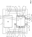
- FIG 1 schematically shows a preferred embodiment of a detection device according to the invention.
- the detection device comprises a housing (“cuvette body”) 1, in which a measuring chamber (“cuvette”) 2 with an inlet 3 and an outlet 4 is arranged.
- the inlet 3 is preferably in fluid communication with an input device, for example with a mouthpiece or with a funnel, into which a person can blow breathing air. Gas, in particular exhaled breathing air, can flow into the measuring chamber 2 through the inlet 3 and flow out of the measuring chamber 2 again through the outlet 4.
- Figure 1 shows schematically a mouthpiece 26 which is in fluid communication with the inlet 3 via a hose 27.
- a closure (not shown), for example a cap, can close the inlet 3 or the mouthpiece 26 or the hose 27.
- a optional flow sensor 17 measures the volume flow that flows through inlet 3 into measuring chamber 2.
- An optional check valve 18 prevents ambient air from flowing into the measuring chamber 2 through the outlet 4 and could falsify measurement results. On the other hand, the check valve 18 enables the gas to flow out of the measuring chamber 2 through the outlet 4.
- An optional filter (not shown) at the inlet 3 prevents water droplets, dust particles or other disruptive particles from entering the measuring chamber 2.
- a heating device (not shown) preferably keeps the air temperature in the measuring chamber 2 at least 40 ° C. This reduces the risk that water condenses on a wall of the measuring chamber 2 and the condensed water can falsify measurement results or damage a component.
- An output unit not shown, outputs an examination result in a form that can be perceived by a person, in particular optically and / or acoustically. At least it is output whether the breath sample contains alcohol in a concentration above a predetermined limit or not, e.g. above a detection limit or above a legally prescribed limit. It is also possible for the output unit to output a measured value relating to the measured alcohol concentration.
- An optional flushing outlet 20 with a pump 19 is arranged at a distance from the inlet 3.
- the pump 19 can suck fluid out of the measurement chamber 2, in particular after a person has entered a breath sample into the measurement chamber 2 and the detection device has automatically examined this breath sample. Alcohol-free ambient air can flow through the inlet 3 into the measuring chamber 2 and replaces the gas sample under investigation. This enables the detection device to be prepared for a new application. It is also possible that the pump 19 conveys an alcohol-containing reference gas sample through the inlet 3 into the measuring chamber 2.
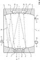
- Figure 2 shows the measuring chamber 2 in detail.
- the measuring chamber 2 is symmetrical with respect to a plane of symmetry 14 which perpendicular to the drawing levels of Figure 1 to Figure 3 stands.
- This plane of symmetry 14 divides the measuring chamber 2 into a first half 15 and a second half 16, which are mirror-symmetrical to one another.
- a first detection unit is thus arranged in the first half 15, which comprises the first IR radiation source 7 and the first IR detector 9.
- a second detection unit is arranged, which comprises the second IR radiation source 9 and the second IR detector 13.
- the measuring chamber 2 can also be constructed asymmetrically.
- Two opposite sides of the measuring chamber 2 are each formed by a concave mirror 5 or 6, namely one side from a transmitter-side concave mirror 5 and an opposite side from a receiver-side concave mirror 6.
- both concave mirrors 5, 6 have the same focal length. Both focal points are ideally located on the optical axis 14.
- a first IR radiation source 7 and a second IR radiation source 11 are embedded in the transmitter-side concave mirror 5, the first IR radiation source 7 belonging to the first half 15 and the second IR radiation source 11 belonging to the second half 16 of the measuring chamber 2.
- a first IR detector 9 and a second IR detector 13 are embedded in the concave mirror 6 on the receiver side, the first IR detector 9 belonging to the first half 15 and the second IR detector 13 belonging to the second half 16 of the measuring chamber 2.
- the first IR detector 9 comprises a first photosensor 24 and a first wavelength filter 8.
- the second IR detector 13 comprises a second photosensor 25 and a second wavelength filter 12.
- a heating element preferably keeps the interior of the measuring chamber 2 at a temperature of at least 40 ° C., so that water is largely prevented from condensing on a concave mirror 5 or 6 or a wavelength filter 8, 12.
- the transmittance of the first wavelength filter 8 is preferably greatest in a first wavelength range, and the transmittance of the second wavelength filter 12 is greatest in a second wavelength range.
- the two wavelength ranges differ and include one common sub-area in which an IR beam is sufficiently attenuated by alcohol in the air we breathe.
- the first wavelength range has a maximum transmission (central wavelength) at 9.6 ⁇ m
- the second wavelength range at 9.2 ⁇ m.
- the two IR detectors 9 and 13 are preferably adjusted or calibrated in such a way that - despite different wavelength ranges - they have the same sensitivity to ethanol, that is to say to alcohol in the breathing air.
- the evaluation unit 10 evaluates the measured values from the two IR detectors 9 and 13 in such a way that the two detection units have different sensitivities for other substances that can be in the exhaled breathing air, for example carbon dioxide, isopropanol, methanol or acetone. In this way, ethanol can be distinguished particularly well from another substance that can be in an entered breath sample.
- the adjustment is carried out by setting the two wavelength filters 8 and 12 accordingly. An example of this is described below.
- each wavelength filter 8 and 12 can be operated either in a first mode or in a second mode.
- the transmission When operating in the first mode, the transmission is greatest in the first wavelength range, when operating in the second mode, the transmission is in the second wavelength range.
- This configuration makes it possible to first operate the first wavelength filter 8 in the first mode and the second wavelength filter 12 in the second mode when examining a breath sample and then vice versa to operate the first wavelength filter 8 in the second mode and the second wavelength filter 12 in the first mode. In this way, the effect of a non-ideal adjustment is at least partially compensated for.
- each IR detector it is possible for each IR detector to deliver two measured values, while the measuring chamber 2 is filled with a breath sample to be examined.
- Figure 2 illustrates an example of the beam path 30 of an IR beam, which the first IR radiation source 7 has emitted into the measuring chamber 2 is reflected several times by both concave mirrors 5 and 6 and then strikes the first IR detector 9. Further illustrated Figure 2 the beam path 31 of an IR beam, which the second IR radiation source 11 has emitted into the measuring chamber 2. In the example shown, each IR beam is reflected seven times after the emission before it occurs on an IR detector 9 or 13.
- FIG Figure 3 shows a modification in which the first beam path 30 and the in Figure 3 Second beam path 31, not shown, each utilize almost the entire measuring chamber 2.
- the second beam path 31, mirror-symmetrical to the first beam path 30, is shown in FIG Figure 3 Not shown.
- the maximum dimension of the measuring chamber 2 parallel to the plane of symmetry 14 is preferably 10 cm. Because each emitted IR beam is reflected several times at the two concave mirrors 5 and 6, each beam path 30 and 31 can have a length of 40 cm or more, the so-called absorption length. The absorption length is six times the distance between the two concave mirrors 5 and 6 in the case of a sixfold reflection. Furthermore, it is possible for the angle of incidence of an IR beam onto an IR detector 9 or 13 to be a maximum of 30 degrees, which leads to a sufficient aperture.
- the measuring chamber 2 with the two concave mirrors 5 and 6 is preferably designed as a Herriott cell.
- the distance d between the two concave mirrors 5 and 6 and the preferably corresponding focal length f of the two concave mirrors 5 and 6 are designed such that the two IR radiation sources 7 and 11 are ideally sharp and on a scale of 1: 1 to the two IR detectors 9 and 13 are shown.
- a specific focal length f of the two concave mirrors 5 and 6 and a specific ratio f / d are specified for a sharp image. This results in a distance d between the two concave mirrors 5 and 6.
- the number of times an emitted IR beam is reflected results in the absorption length achieved. A slight misalignment of a concave mirror 5 or 6 therefore only slightly impairs the measurement results.
- An optional first adjustable deflection device 21 can either direct an IR beam, which the first IR radiation source 7 has emitted, onto the first IR detector 9 or the second IR detector 13 or at least change the direction of the IR beam.
- the deflection device 21 can rotate the first IR radiation source 7.
- An optional second deflection device, not shown, can selectively direct an IR beam, which the second IR radiation source 11 has emitted, onto the first IR detector 9 or the second IR detector 13. This configuration makes it possible to operate the detection device with two IR detectors 9 and 13 even if one of the two IR radiation sources 7 or 11 has failed. In addition, a slightly incorrect position of an IR radiation source 7, 11 or an IR detector 9, 13 can be corrected.
- a data processing evaluation unit 10 can transmit control commands to the first IR radiation source 7, the second IR radiation source 11 and the pump 19 and optionally to a deflection unit 21 via control lines 22.
- the first photosensor 24 and the second photosensor 25 each independently generate at least one measurement value, these measurement values each depending on the intensity of an IR beam 30, 31 impinging on the photosensor 24 or 25. Measured values are transmitted from the first photosensor 24, the second photosensor 25 and the flow sensor 17 to the evaluation unit 10 via sensor lines 23.
- the detection device of the exemplary embodiment furthermore comprises a separate energy supply (not shown) for electrical energy, for example a set of rechargeable batteries, which make the detection device independent of a stationary supply.
- a separate energy supply for electrical energy, for example a set of rechargeable batteries, which make the detection device independent of a stationary supply.
- the evaluation unit 10 activates the pump 19 via a control line 22.
- the activated pump 19 draws gas from the measuring chamber 2.
- the extracted gas is replaced by ambient air, which flows through the inlet 3 into the measuring chamber 2 in order to compensate for the negative pressure generated.
- gas from a previous breath sample is replaced by a alcohol-free reference gas sample replaced. Therefore, a previous gas sample cannot falsify the result.
- the evaluation unit 10 evaluates a measured value from the flow sensor 17 and detects the event that the volume of the ambient air drawn into the measuring chamber 2 is at least as large as the volume of the measuring chamber 2. The evaluation unit 10 switches the pump 19 off again as soon as this event is detected. An alcohol-free gas sample is now located in the measuring chamber 2.
- a first zero measured value 10 (1) and a second zero measured value 10 (2) are read from a data memory.
- both IR radiation sources 7 and 11 each emit an IR beam, and the two IR detectors 9 and 13 measure the first zero measurement value 10 (1) and the second zero measurement value 10 (2).
- the two zero measured values 10 (1) and 10 (2) of the two IR detectors 9 and 13 are present when the gas in the measuring chamber 2 contains no alcohol.
- the configuration of measuring the two zero measurement values 10 (1) and 10 (2) again before each alcohol sample has the following advantage in particular: A gradual change in a component of the detection device is automatically compensated for. In particular, a gradual change in an IR radiation source 7, 11 or an IR detector 9, 13 or the voltage source is compensated for. It is sufficient that the two IR radiation sources 7, 11 and the two IR detectors 9, 13 remain practically unchanged during a single alcohol measurement.
- a breath sample with breathing air to be examined is brought into the measuring chamber 2 through the inlet 3.
- a person blows into the mouthpiece 26 and the input air flows through the hose 27 and the inlet 3 into the measuring chamber 2.
- the first IR radiation source 7 emits an IR beam into the measuring chamber 2.
- the emitted IR beam penetrates the measuring chamber 2 along the first beam path 30 and strikes the first IR detector 9.
- the second IR radiation source 11 likewise emits an IR beam into the measuring chamber 2.
- the emitted IR beam penetrates the measuring chamber 2 along the second beam path 31 and strikes the second IR detector 13.
- the IR radiation sources 7 and 11 each emit an IR beam overlapping in time or even simultaneously. It is also possible that the two IR radiation sources 7 and 11 each emit an IR beam in succession.
- Each IR detector 9, 13 delivers a measured value 11 (1) or 11 (2) for the light intensity that occurs at the photosensor 24 or 25 while the breath sample is in the measuring chamber 2.
- the calibration factors k1 and k2 are predetermined or have been determined in advance and are stored in a data memory of the detection device.
- the calibration factors k1 and k2 were set, for example, as described above.
- the two signals C (1) and C (2) ideally match.
- the evaluation unit 10 preferably checks whether the absolute or percentage deviation between the two signals C (1) and C (2) lies below a predetermined limit. If this is the case, the measurement result is considered correct.
- the barrier is set so low that the result in the event of a discrepancy between the two signals C (1) and C (2) below the barrier is trustworthy, even if other substances and also interfering radiation have entered the measuring chamber 2.
- the barrier is set so high that the inevitable deviations between the measurement results of the two IR detectors 9 and 13 does not lead to a correct result being rejected.
Landscapes
- Health & Medical Sciences (AREA)
- Life Sciences & Earth Sciences (AREA)
- Physics & Mathematics (AREA)
- Chemical & Material Sciences (AREA)
- Engineering & Computer Science (AREA)
- Pathology (AREA)
- General Health & Medical Sciences (AREA)
- Immunology (AREA)
- Biochemistry (AREA)
- Analytical Chemistry (AREA)
- General Physics & Mathematics (AREA)
- Spectroscopy & Molecular Physics (AREA)
- Biomedical Technology (AREA)
- Molecular Biology (AREA)
- Food Science & Technology (AREA)
- Medicinal Chemistry (AREA)
- Hematology (AREA)
- Urology & Nephrology (AREA)
- Combustion & Propulsion (AREA)
- Surgery (AREA)
- Heart & Thoracic Surgery (AREA)
- Microbiology (AREA)
- Cell Biology (AREA)
- Public Health (AREA)
- Medical Informatics (AREA)
- Biotechnology (AREA)
- Animal Behavior & Ethology (AREA)
- Biophysics (AREA)
- Pulmonology (AREA)
- Veterinary Medicine (AREA)
- Physiology (AREA)
- Investigating Or Analysing Materials By Optical Means (AREA)
- Investigating Or Analysing Biological Materials (AREA)
Applications Claiming Priority (1)
| Application Number | Priority Date | Filing Date | Title |
|---|---|---|---|
| DE102018009981.5A DE102018009981A1 (de) | 2018-12-21 | 2018-12-21 | Alkoholdetektionsvorrichtung mit redundanten Messkanälen und Verfahren zum Messen einer Ethanolkonzentration in Atemluft |
Publications (2)
| Publication Number | Publication Date |
|---|---|
| EP3671184A1 true EP3671184A1 (fr) | 2020-06-24 |
| EP3671184B1 EP3671184B1 (fr) | 2022-08-31 |
Family
ID=68965841
Family Applications (1)
| Application Number | Title | Priority Date | Filing Date |
|---|---|---|---|
| EP19217925.7A Active EP3671184B1 (fr) | 2018-12-21 | 2019-12-19 | Dispositif de détection d'alcool doté de canaux de mesure redondants et procédé pour détecter d'alcool |
Country Status (4)
| Country | Link |
|---|---|
| US (1) | US11181472B2 (fr) |
| EP (1) | EP3671184B1 (fr) |
| CA (1) | CA3065699C (fr) |
| DE (1) | DE102018009981A1 (fr) |
Cited By (1)
| Publication number | Priority date | Publication date | Assignee | Title |
|---|---|---|---|---|
| WO2023079155A1 (fr) * | 2021-11-08 | 2023-05-11 | Helmut-Schmidt-Universität/Universität Der Bundeswehr Hamburg | Agencement à passages multiples et dispositif d'élargissement spectral de rayonnement laser |
Families Citing this family (2)
| Publication number | Priority date | Publication date | Assignee | Title |
|---|---|---|---|---|
| KR102450625B1 (ko) * | 2017-08-31 | 2022-10-07 | 서울바이오시스 주식회사 | 검출기 |
| CN115015150A (zh) * | 2022-05-25 | 2022-09-06 | 中国船舶重工集团公司第七0三研究所 | 一种多通道冗余型高精度可燃气体浓度传感器 |
Citations (2)
| Publication number | Priority date | Publication date | Assignee | Title |
|---|---|---|---|---|
| US20020036266A1 (en) * | 2000-09-27 | 2002-03-28 | Peter Dreyer | Infrared optical gas analyzer |
| US20180116555A1 (en) * | 2016-10-28 | 2018-05-03 | Drägerwerk AG & Co. KGaA | Device for determining the concentration of at least one gas component in a breathing gas mixture |
Family Cites Families (13)
| Publication number | Priority date | Publication date | Assignee | Title |
|---|---|---|---|---|
| US5420061A (en) | 1993-08-13 | 1995-05-30 | Micron Semiconductor, Inc. | Method for improving latchup immunity in a dual-polysilicon gate process |
| US5515859A (en) * | 1993-08-24 | 1996-05-14 | Colorado Health Care Research Corp. | Myocardial infarction and ischemia detection method and apparatus |
| DE4344196C2 (de) | 1993-12-23 | 1997-08-07 | Draegerwerk Ag | Verfahren zur Bestimmung von Kenngrößen einer elektrochemisch umsetzbaren Substanz in einer Gasprobe |
| DE19607062C2 (de) | 1996-02-24 | 1998-02-19 | Draegerwerk Ag | Verfahren zur Bestimmung der Ethanolkonzentration in einer Atemgasprobe |
| DE19619673C2 (de) | 1996-05-15 | 1998-11-05 | Draegerwerk Ag | Vorrichtung zur Kalibrierung eines Gasmeßgerätes |
| DE19913783C1 (de) | 1999-03-26 | 2000-03-09 | Draeger Sicherheitstech Gmbh | Atemalkohol-Meßgerät mit einem im Probenahmekanal angeordneten Temperaturfühler |
| DE10216653A1 (de) * | 2002-04-15 | 2003-11-06 | Biotechnologie Kempe Gmbh | Sonde zur Alkoholmessung in Flüssigkeiten |
| DE102004006677A1 (de) * | 2004-02-11 | 2005-09-15 | Kendro Laboratory Products Gmbh | Infrarot-Gassensor und Verfahren zur Gaskonzentrationsmessung mit diesem Sensor |
| DE102006018970B3 (de) | 2006-04-25 | 2007-05-03 | Dräger Safety AG & Co. KGaA | Atemalkoholmessgerät mit Piezoantrieb |
| DE102011106410B3 (de) * | 2011-07-02 | 2012-08-02 | Dräger Safety Ag & Co.Kgaa | Atemalkoholgehaltmessgerät |
| DE102012007030C5 (de) | 2012-04-05 | 2019-01-10 | Drägerwerk AG & Co. KGaA | Vorrichtung und Verfahren zur schnellen Aufnahme eines Absorptionsspektrums eines Fluids |
| DE102014014872A1 (de) | 2014-10-06 | 2016-04-07 | Dräger Safety AG & Co. KGaA | System zur transkutanen Bestimmung der Blutalkoholkonzentration |
| DE102016003285A1 (de) | 2016-03-18 | 2017-09-21 | Dräger Safety AG & Co. KGaA | In-situ-Gasmesssystem für Gasreaktoren mit kritischen Umgebungen |
-
2018
- 2018-12-21 DE DE102018009981.5A patent/DE102018009981A1/de not_active Withdrawn
-
2019
- 2019-12-18 CA CA3065699A patent/CA3065699C/fr active Active
- 2019-12-19 EP EP19217925.7A patent/EP3671184B1/fr active Active
- 2019-12-20 US US16/723,045 patent/US11181472B2/en active Active
Patent Citations (2)
| Publication number | Priority date | Publication date | Assignee | Title |
|---|---|---|---|---|
| US20020036266A1 (en) * | 2000-09-27 | 2002-03-28 | Peter Dreyer | Infrared optical gas analyzer |
| US20180116555A1 (en) * | 2016-10-28 | 2018-05-03 | Drägerwerk AG & Co. KGaA | Device for determining the concentration of at least one gas component in a breathing gas mixture |
Cited By (1)
| Publication number | Priority date | Publication date | Assignee | Title |
|---|---|---|---|---|
| WO2023079155A1 (fr) * | 2021-11-08 | 2023-05-11 | Helmut-Schmidt-Universität/Universität Der Bundeswehr Hamburg | Agencement à passages multiples et dispositif d'élargissement spectral de rayonnement laser |
Also Published As
| Publication number | Publication date |
|---|---|
| CA3065699A1 (fr) | 2020-06-21 |
| US11181472B2 (en) | 2021-11-23 |
| CA3065699C (fr) | 2023-01-17 |
| EP3671184B1 (fr) | 2022-08-31 |
| US20200200676A1 (en) | 2020-06-25 |
| DE102018009981A1 (de) | 2020-06-25 |
Similar Documents
| Publication | Publication Date | Title |
|---|---|---|
| DE69828799T2 (de) | Isotopengas-analysator | |
| DE19925196C2 (de) | Gassensoranordnung | |
| EP2260290B1 (fr) | Procédé et dispositif de mesure de turbidité | |
| DE3885104T2 (de) | Mehrkanal-vorrichtung zur analysierung von molekulargasen unter verwendung der laser-erregten raman-lichtstreuung. | |
| DE3932838C2 (de) | Nichtdispersiver Infrarot-Gasanalysator | |
| DE60300172T2 (de) | Vorrichtung und Methode zur Messung von Atemalkohol | |
| EP3671184B1 (fr) | Dispositif de détection d'alcool doté de canaux de mesure redondants et procédé pour détecter d'alcool | |
| DE102008009189B4 (de) | Nichtdispersiver Infrarot-Gasanalysator | |
| DE69722794T2 (de) | Vorrichtung und verfahren zur optischen analyse von umgebungsluft | |
| EP2003441A1 (fr) | Capteur ATR | |
| WO2001063253A1 (fr) | Systeme de mesure optique | |
| DE3814718A1 (de) | Messeinrichtung zum analysieren mittels infrarotstrahlung | |
| DE4443016A1 (de) | Gasanalytisches Meßgerät | |
| DE102021118119A1 (de) | Photoakustischer Sensor mit Ersatzgas und Detektions-Verfahren unter Verwendung eines solchen Sensors | |
| EP3963309B1 (fr) | Capteur de gaz infrarouge multicanaux compensé contre des perturbations mécaniques | |
| EP0952441B1 (fr) | Procédé pour déterminer la fluorescence induite par le soleil | |
| EP1287335B1 (fr) | Procede et dispositif permettant de determiner la composition du melange de fluides quelconques et de mesurer la quantite de matiere | |
| DE102017130988B4 (de) | Vorrichtungen und verfahren zur nutzung des photoakustischen effekts | |
| DE102009058394B3 (de) | Verfahren zur Messung der Konzentration mindestens einer Gaskomponente in einem Messgas | |
| EP4127656B1 (fr) | Procédé et dispositif de mesure d'aérosol pour déterminer une distribution granulométrique basée sur une source d'un aérosol | |
| DE102018202072A1 (de) | System und Verfahren zur Bestimmung einer Konzentration eines Dekontaminierungsmittels | |
| AT515495A2 (de) | Verfahren und Vorrichtung zur Bestimmung einer Partikelkonzentration eines mit Partikel geladenen Messgases | |
| DE102018129182A1 (de) | Verfahren und Vorrichtung zur Messung eines in einem Rohgas enthaltenen Messbestandteils | |
| DE102004034832B4 (de) | Verfahren und Anordnung zur Gasanalyse | |
| EP1659393B1 (fr) | Analyseur de gaz à infrarouge non dispersif selon le principe du double faisceau |
Legal Events
| Date | Code | Title | Description |
|---|---|---|---|
| PUAI | Public reference made under article 153(3) epc to a published international application that has entered the european phase |
Free format text: ORIGINAL CODE: 0009012 |
|
| STAA | Information on the status of an ep patent application or granted ep patent |
Free format text: STATUS: THE APPLICATION HAS BEEN PUBLISHED |
|
| STAA | Information on the status of an ep patent application or granted ep patent |
Free format text: STATUS: REQUEST FOR EXAMINATION WAS MADE |
|
| AK | Designated contracting states |
Kind code of ref document: A1 Designated state(s): AL AT BE BG CH CY CZ DE DK EE ES FI FR GB GR HR HU IE IS IT LI LT LU LV MC MK MT NL NO PL PT RO RS SE SI SK SM TR |
|
| AX | Request for extension of the european patent |
Extension state: BA ME |
|
| 17P | Request for examination filed |
Effective date: 20200616 |
|
| RBV | Designated contracting states (corrected) |
Designated state(s): AL AT BE BG CH CY CZ DE DK EE ES FI FR GB GR HR HU IE IS IT LI LT LU LV MC MK MT NL NO PL PT RO RS SE SI SK SM TR |
|
| GRAP | Despatch of communication of intention to grant a patent |
Free format text: ORIGINAL CODE: EPIDOSNIGR1 |
|
| STAA | Information on the status of an ep patent application or granted ep patent |
Free format text: STATUS: GRANT OF PATENT IS INTENDED |
|
| INTG | Intention to grant announced |
Effective date: 20220530 |
|
| GRAS | Grant fee paid |
Free format text: ORIGINAL CODE: EPIDOSNIGR3 |
|
| GRAA | (expected) grant |
Free format text: ORIGINAL CODE: 0009210 |
|
| STAA | Information on the status of an ep patent application or granted ep patent |
Free format text: STATUS: THE PATENT HAS BEEN GRANTED |
|
| AK | Designated contracting states |
Kind code of ref document: B1 Designated state(s): AL AT BE BG CH CY CZ DE DK EE ES FI FR GB GR HR HU IE IS IT LI LT LU LV MC MK MT NL NO PL PT RO RS SE SI SK SM TR |
|
| REG | Reference to a national code |
Ref country code: CH Ref legal event code: EP Ref country code: GB Ref legal event code: FG4D Free format text: NOT ENGLISH |
|
| REG | Reference to a national code |
Ref country code: AT Ref legal event code: REF Ref document number: 1515641 Country of ref document: AT Kind code of ref document: T Effective date: 20220915 Ref country code: DE Ref legal event code: R096 Ref document number: 502019005486 Country of ref document: DE |
|
| REG | Reference to a national code |
Ref country code: IE Ref legal event code: FG4D Free format text: LANGUAGE OF EP DOCUMENT: GERMAN |
|
| REG | Reference to a national code |
Ref country code: LT Ref legal event code: MG9D |
|
| REG | Reference to a national code |
Ref country code: NL Ref legal event code: MP Effective date: 20220831 |
|
| PG25 | Lapsed in a contracting state [announced via postgrant information from national office to epo] |
Ref country code: SE Free format text: LAPSE BECAUSE OF FAILURE TO SUBMIT A TRANSLATION OF THE DESCRIPTION OR TO PAY THE FEE WITHIN THE PRESCRIBED TIME-LIMIT Effective date: 20220831 Ref country code: RS Free format text: LAPSE BECAUSE OF FAILURE TO SUBMIT A TRANSLATION OF THE DESCRIPTION OR TO PAY THE FEE WITHIN THE PRESCRIBED TIME-LIMIT Effective date: 20220831 Ref country code: NO Free format text: LAPSE BECAUSE OF FAILURE TO SUBMIT A TRANSLATION OF THE DESCRIPTION OR TO PAY THE FEE WITHIN THE PRESCRIBED TIME-LIMIT Effective date: 20221130 Ref country code: LV Free format text: LAPSE BECAUSE OF FAILURE TO SUBMIT A TRANSLATION OF THE DESCRIPTION OR TO PAY THE FEE WITHIN THE PRESCRIBED TIME-LIMIT Effective date: 20220831 Ref country code: LT Free format text: LAPSE BECAUSE OF FAILURE TO SUBMIT A TRANSLATION OF THE DESCRIPTION OR TO PAY THE FEE WITHIN THE PRESCRIBED TIME-LIMIT Effective date: 20220831 Ref country code: FI Free format text: LAPSE BECAUSE OF FAILURE TO SUBMIT A TRANSLATION OF THE DESCRIPTION OR TO PAY THE FEE WITHIN THE PRESCRIBED TIME-LIMIT Effective date: 20220831 |
|
| PG25 | Lapsed in a contracting state [announced via postgrant information from national office to epo] |
Ref country code: PL Free format text: LAPSE BECAUSE OF FAILURE TO SUBMIT A TRANSLATION OF THE DESCRIPTION OR TO PAY THE FEE WITHIN THE PRESCRIBED TIME-LIMIT Effective date: 20220831 Ref country code: IS Free format text: LAPSE BECAUSE OF FAILURE TO SUBMIT A TRANSLATION OF THE DESCRIPTION OR TO PAY THE FEE WITHIN THE PRESCRIBED TIME-LIMIT Effective date: 20221231 Ref country code: HR Free format text: LAPSE BECAUSE OF FAILURE TO SUBMIT A TRANSLATION OF THE DESCRIPTION OR TO PAY THE FEE WITHIN THE PRESCRIBED TIME-LIMIT Effective date: 20220831 Ref country code: GR Free format text: LAPSE BECAUSE OF FAILURE TO SUBMIT A TRANSLATION OF THE DESCRIPTION OR TO PAY THE FEE WITHIN THE PRESCRIBED TIME-LIMIT Effective date: 20221201 |
|
| PG25 | Lapsed in a contracting state [announced via postgrant information from national office to epo] |
Ref country code: SM Free format text: LAPSE BECAUSE OF FAILURE TO SUBMIT A TRANSLATION OF THE DESCRIPTION OR TO PAY THE FEE WITHIN THE PRESCRIBED TIME-LIMIT Effective date: 20220831 Ref country code: RO Free format text: LAPSE BECAUSE OF FAILURE TO SUBMIT A TRANSLATION OF THE DESCRIPTION OR TO PAY THE FEE WITHIN THE PRESCRIBED TIME-LIMIT Effective date: 20220831 Ref country code: PT Free format text: LAPSE BECAUSE OF FAILURE TO SUBMIT A TRANSLATION OF THE DESCRIPTION OR TO PAY THE FEE WITHIN THE PRESCRIBED TIME-LIMIT Effective date: 20230102 Ref country code: ES Free format text: LAPSE BECAUSE OF FAILURE TO SUBMIT A TRANSLATION OF THE DESCRIPTION OR TO PAY THE FEE WITHIN THE PRESCRIBED TIME-LIMIT Effective date: 20220831 Ref country code: DK Free format text: LAPSE BECAUSE OF FAILURE TO SUBMIT A TRANSLATION OF THE DESCRIPTION OR TO PAY THE FEE WITHIN THE PRESCRIBED TIME-LIMIT Effective date: 20220831 Ref country code: CZ Free format text: LAPSE BECAUSE OF FAILURE TO SUBMIT A TRANSLATION OF THE DESCRIPTION OR TO PAY THE FEE WITHIN THE PRESCRIBED TIME-LIMIT Effective date: 20220831 |
|
| PG25 | Lapsed in a contracting state [announced via postgrant information from national office to epo] |
Ref country code: SK Free format text: LAPSE BECAUSE OF FAILURE TO SUBMIT A TRANSLATION OF THE DESCRIPTION OR TO PAY THE FEE WITHIN THE PRESCRIBED TIME-LIMIT Effective date: 20220831 Ref country code: EE Free format text: LAPSE BECAUSE OF FAILURE TO SUBMIT A TRANSLATION OF THE DESCRIPTION OR TO PAY THE FEE WITHIN THE PRESCRIBED TIME-LIMIT Effective date: 20220831 |
|
| REG | Reference to a national code |
Ref country code: DE Ref legal event code: R097 Ref document number: 502019005486 Country of ref document: DE |
|
| PG25 | Lapsed in a contracting state [announced via postgrant information from national office to epo] |
Ref country code: NL Free format text: LAPSE BECAUSE OF FAILURE TO SUBMIT A TRANSLATION OF THE DESCRIPTION OR TO PAY THE FEE WITHIN THE PRESCRIBED TIME-LIMIT Effective date: 20220831 Ref country code: AL Free format text: LAPSE BECAUSE OF FAILURE TO SUBMIT A TRANSLATION OF THE DESCRIPTION OR TO PAY THE FEE WITHIN THE PRESCRIBED TIME-LIMIT Effective date: 20220831 |
|
| PLBE | No opposition filed within time limit |
Free format text: ORIGINAL CODE: 0009261 |
|
| STAA | Information on the status of an ep patent application or granted ep patent |
Free format text: STATUS: NO OPPOSITION FILED WITHIN TIME LIMIT |
|
| REG | Reference to a national code |
Ref country code: CH Ref legal event code: PL |
|
| 26N | No opposition filed |
Effective date: 20230601 |
|
| REG | Reference to a national code |
Ref country code: BE Ref legal event code: MM Effective date: 20221231 |
|
| PG25 | Lapsed in a contracting state [announced via postgrant information from national office to epo] |
Ref country code: SI Free format text: LAPSE BECAUSE OF FAILURE TO SUBMIT A TRANSLATION OF THE DESCRIPTION OR TO PAY THE FEE WITHIN THE PRESCRIBED TIME-LIMIT Effective date: 20220831 Ref country code: LU Free format text: LAPSE BECAUSE OF NON-PAYMENT OF DUE FEES Effective date: 20221219 |
|
| PG25 | Lapsed in a contracting state [announced via postgrant information from national office to epo] |
Ref country code: LI Free format text: LAPSE BECAUSE OF NON-PAYMENT OF DUE FEES Effective date: 20221231 Ref country code: IE Free format text: LAPSE BECAUSE OF NON-PAYMENT OF DUE FEES Effective date: 20221219 Ref country code: CH Free format text: LAPSE BECAUSE OF NON-PAYMENT OF DUE FEES Effective date: 20221231 |
|
| PG25 | Lapsed in a contracting state [announced via postgrant information from national office to epo] |
Ref country code: BE Free format text: LAPSE BECAUSE OF NON-PAYMENT OF DUE FEES Effective date: 20221231 |
|
| PG25 | Lapsed in a contracting state [announced via postgrant information from national office to epo] |
Ref country code: HU Free format text: LAPSE BECAUSE OF FAILURE TO SUBMIT A TRANSLATION OF THE DESCRIPTION OR TO PAY THE FEE WITHIN THE PRESCRIBED TIME-LIMIT; INVALID AB INITIO Effective date: 20191219 |
|
| PG25 | Lapsed in a contracting state [announced via postgrant information from national office to epo] |
Ref country code: CY Free format text: LAPSE BECAUSE OF FAILURE TO SUBMIT A TRANSLATION OF THE DESCRIPTION OR TO PAY THE FEE WITHIN THE PRESCRIBED TIME-LIMIT Effective date: 20220831 |
|
| PG25 | Lapsed in a contracting state [announced via postgrant information from national office to epo] |
Ref country code: MK Free format text: LAPSE BECAUSE OF FAILURE TO SUBMIT A TRANSLATION OF THE DESCRIPTION OR TO PAY THE FEE WITHIN THE PRESCRIBED TIME-LIMIT Effective date: 20220831 Ref country code: IT Free format text: LAPSE BECAUSE OF FAILURE TO SUBMIT A TRANSLATION OF THE DESCRIPTION OR TO PAY THE FEE WITHIN THE PRESCRIBED TIME-LIMIT Effective date: 20220831 |
|
| PG25 | Lapsed in a contracting state [announced via postgrant information from national office to epo] |
Ref country code: MC Free format text: LAPSE BECAUSE OF FAILURE TO SUBMIT A TRANSLATION OF THE DESCRIPTION OR TO PAY THE FEE WITHIN THE PRESCRIBED TIME-LIMIT Effective date: 20220831 |
|
| PG25 | Lapsed in a contracting state [announced via postgrant information from national office to epo] |
Ref country code: TR Free format text: LAPSE BECAUSE OF FAILURE TO SUBMIT A TRANSLATION OF THE DESCRIPTION OR TO PAY THE FEE WITHIN THE PRESCRIBED TIME-LIMIT Effective date: 20220831 Ref country code: MC Free format text: LAPSE BECAUSE OF FAILURE TO SUBMIT A TRANSLATION OF THE DESCRIPTION OR TO PAY THE FEE WITHIN THE PRESCRIBED TIME-LIMIT Effective date: 20220831 |
|
| PG25 | Lapsed in a contracting state [announced via postgrant information from national office to epo] |
Ref country code: BG Free format text: LAPSE BECAUSE OF FAILURE TO SUBMIT A TRANSLATION OF THE DESCRIPTION OR TO PAY THE FEE WITHIN THE PRESCRIBED TIME-LIMIT Effective date: 20220831 |
|
| PG25 | Lapsed in a contracting state [announced via postgrant information from national office to epo] |
Ref country code: MT Free format text: LAPSE BECAUSE OF FAILURE TO SUBMIT A TRANSLATION OF THE DESCRIPTION OR TO PAY THE FEE WITHIN THE PRESCRIBED TIME-LIMIT Effective date: 20220831 |
|
| PGFP | Annual fee paid to national office [announced via postgrant information from national office to epo] |
Ref country code: GB Payment date: 20251218 Year of fee payment: 7 |
|
| PGFP | Annual fee paid to national office [announced via postgrant information from national office to epo] |
Ref country code: FR Payment date: 20251218 Year of fee payment: 7 |
|
| REG | Reference to a national code |
Ref country code: AT Ref legal event code: MM01 Ref document number: 1515641 Country of ref document: AT Kind code of ref document: T Effective date: 20241219 |
|
| PGFP | Annual fee paid to national office [announced via postgrant information from national office to epo] |
Ref country code: DE Payment date: 20251222 Year of fee payment: 7 |
|
| PG25 | Lapsed in a contracting state [announced via postgrant information from national office to epo] |
Ref country code: AT Free format text: LAPSE BECAUSE OF NON-PAYMENT OF DUE FEES Effective date: 20241219 |
|
| PGFP | Annual fee paid to national office [announced via postgrant information from national office to epo] |
Ref country code: AT Payment date: 20260410 Year of fee payment: 5 |