EP3671793A1 - Agencement de circuit - Google Patents
Agencement de circuit Download PDFInfo
- Publication number
- EP3671793A1 EP3671793A1 EP19214338.6A EP19214338A EP3671793A1 EP 3671793 A1 EP3671793 A1 EP 3671793A1 EP 19214338 A EP19214338 A EP 19214338A EP 3671793 A1 EP3671793 A1 EP 3671793A1
- Authority
- EP
- European Patent Office
- Prior art keywords
- conductor path
- interruption
- conductor
- circuit arrangement
- arrangement
- Prior art date
- Legal status (The legal status is an assumption and is not a legal conclusion. Google has not performed a legal analysis and makes no representation as to the accuracy of the status listed.)
- Withdrawn
Links
Images
Classifications
-
- H—ELECTRICITY
- H01—ELECTRIC ELEMENTS
- H01H—ELECTRIC SWITCHES; RELAYS; SELECTORS; EMERGENCY PROTECTIVE DEVICES
- H01H33/00—High-tension or heavy-current switches with arc-extinguishing or arc-preventing means
- H01H33/02—Details
- H01H33/04—Means for extinguishing or preventing arc between current-carrying parts
- H01H33/16—Impedances connected with contacts
-
- H—ELECTRICITY
- H01—ELECTRIC ELEMENTS
- H01H—ELECTRIC SWITCHES; RELAYS; SELECTORS; EMERGENCY PROTECTIVE DEVICES
- H01H9/00—Details of switching devices, not covered by groups H01H1/00 - H01H7/00
- H01H9/30—Means for extinguishing or preventing arc between current-carrying parts
- H01H9/42—Impedances connected with contacts
-
- H—ELECTRICITY
- H01—ELECTRIC ELEMENTS
- H01H—ELECTRIC SWITCHES; RELAYS; SELECTORS; EMERGENCY PROTECTIVE DEVICES
- H01H39/00—Switching devices actuated by an explosion produced within the device and initiated by an electric current
- H01H2039/008—Switching devices actuated by an explosion produced within the device and initiated by an electric current using the switch for a battery cutoff
-
- H—ELECTRICITY
- H01—ELECTRIC ELEMENTS
- H01H—ELECTRIC SWITCHES; RELAYS; SELECTORS; EMERGENCY PROTECTIVE DEVICES
- H01H39/00—Switching devices actuated by an explosion produced within the device and initiated by an electric current
- H01H39/006—Opening by severing a conductor
Definitions
- the subject relates to a circuit arrangement and a method for operating a circuit arrangement.
- the subject matter relates to a circuit arrangement and a method for operating a circuit arrangement in automotive applications, in particular in a drive train of an automobile.
- Electrically powered vehicles whether purely electric, hybrid or plug-in hybrid, require very high electrical power in the electric drive train. These are made available via energy storage devices, for example lithium-ion batteries. In order to provide sufficient electrical energy on the drive train, high currents flow between the energy store and the motor with high voltages at the same time.
- the object was therefore based on the object of providing a circuit arrangement which switches reliably under load, even at high currents.
- the circuit arrangement is formed by two electrical conductor paths that run electrically parallel to one another.
- the conductor paths are formed in particular from mechanically stable metal sheets.
- the conductor paths have a conductor cross section of greater than 25 mm 2 , in particular greater than 50 mm 2 .
- the conductor paths are formed in particular from flat parts.
- the two conductor paths can be contacted via a common connection point. Starting from this common connection point, the conductor paths branch into the first and the second conductor path.
- both the first conductor path and the second conductor path can have a separate connection point.
- a high current resistor is arranged on the second conductor path.
- a high current resistor has a current carrying capacity of more than 10kA, especially over 30kA.
- a high-current resistor in particular has an ohmic resistance of a few m ⁇ to a few ⁇ .
- the high-current resistor is preferably arranged between the connection points on the output side of the first and second conductor paths, so that contact can be made with the circuit arrangement directly between the common connection point on the input side and the connection point of the second conductor path on the output side.
- a current flows, in particular for the electric motor of the vehicle, from the connection point on the input side to the connection point on the output side of the first conductor path.
- the high-current resistor is arranged in the second conductor path, so that the current essentially flows via the first conductor path.
- the circuit arrangement has a first interruption arrangement for the electrical and mechanical interruption of the first electrical conductor path and a second interruption arrangement for the electrical and mechanical interruption of the second conductor path.
- the two interruption arrangements are formed as electrical break contacts, but also serve to mechanically cut the respective conductor paths.
- the first and the second interruption arrangement are mechanically coupled to one another in such a way that, after activation, the first interruption arrangement first cuts through the first conductor path and then the second interruption arrangement cuts through the second conductor path.
- the two interruption arrangements carry out a cascaded separation of the conductor paths, which takes place in a targeted and time-schedulable manner due to the mechanical coupling of the two interruption arrangements.
- the two interruption arrangements are activated, for example, by an airbag control signal or another crash signal. If such a signal is present, the interruption arrangements are mechanically accelerated in the direction of the conductor paths.
- the kinetic energy transmitted by the mechanical drive to the first interruption arrangement has the effect that the first interruption arrangement first mechanically cuts through the first conductor path and thus brings about an electrical separation. Since the interruption arrangements are mechanically coupled, the second interruption arrangement is also driven and accelerated by the drive. The kinetic energy transmitted to the second interruption arrangement by the mechanical drive causes the second interruption arrangement to follow the first separation mechanically cuts the second conductor path and thus causes an electrical separation. The second separation takes place immediately after the first separation. The second conductor path is interrupted by the second interrupt arrangement.
- the two interruption arrangements can be formed in one piece.
- the two interruption arrangements can be formed by a common component, in particular a bolt or a sheet metal.
- the two interruption arrangements can be formed by a common cutting device which is arranged relative to the first and the second conductor path in such a way that after activation the first conductor path and then the second conductor path are cut through.
- a drive is triggered which accelerates the two interruption arrangements in the direction of the conductor paths in a translatory or rotary manner.
- the cutting device can also be a bolt which is moved in translation along a trajectory through the conductor paths.
- the conductor paths can be arranged along the trajectory one behind the other, spaced apart from one another, so that the bolt first cuts through the first conductor path and then strikes the second conductor paths and cuts them.
- the combination of the first conductor path with the bolt and a bearing of the first conductor path is the first interrupt arrangement and the combination of the second conductor path with the bolt and a bearing of the second conductor path is the second interrupt arrangement.
- the first interruption arrangement cuts through the first conductor path under load, an arc which would be difficult to extinguish would occur immediately at the separation point without the current being able to commute to the second conductor path.
- the current commutates through the electrically arranged second conductor path but immediately after the first conductor path is separated from the second conductor path. Due to the high current resistance that is between the second conductor path and the load, no appreciable current normally flows through this second conductor path. If the first conductor path is cut, the current can only flow to the load via the second conductor path. Due to the high current resistance arranged on the second conductor path, the commutated current is reduced directly compared to the current on the first conductor path. This reduction means that when the second conductor path is subsequently cut, which likewise takes place under load but with reduced current, there is no longer an arc or the arc that arises can be extinguished more easily.
- the first and the second conductor path are formed on a common conductor plate.
- a stamping process it is possible to stamp two conductor paths from a sheet which can have a common connection potential on the input side and can each have a separate connection point on the output side. The two connection points on the output side can then be connected to each other via the high-current resistor.
- connection tabs or connection openings can be punched. It is also possible to apply a connecting bolt to the printed circuit board, for example by means of screws or welding.
- the conductor plate is formed in particular from copper or a copper alloy.
- the printed circuit board can be coated at the input and / or output-side connection points or can be bimetallic, so that contact with an electrical conductor made of a different metal material than that of the printed circuit board is also possible.
- the connection points on the output side can be coated or bimetallic so that the conductor material of the high-current resistor in the electrochemical voltage series is close to the coating material of the conductor plate.
- the transition voltage is less than 0.7V.
- the first and / or the second interruption arrangement have a preferably common, in particular one-piece, cutting edge.
- the two interruption arrangements can be formed by one and the same cutting edge, which first separates the first conductor path and then the second conductor path due to their arrangement relative to the two conductor paths.
- the cutting edge can be designed in such a way that it shears through the conductor paths.
- the cutting edge is arranged on a first side of the conductor paths and that an abutment to the cutting edge is arranged on the side of the conductor paths opposite the first side.
- the conductor paths can be formed from sheet metal. These metal sheets have two opposite, wide surfaces. These wide surfaces can face the cutting edge and the counter bearing. After activation, the cutting edge hits the first side of the conductor paths, is pressed against the conductor paths with a force and thereby shears off the conductor paths on the counter bearing.
- both the electrical conductor and the interruption of the electrical conductor can be formed in one structural unit.
- the cutting edge is preferably arranged pivotably on a joint.
- the joint is preferably such that its pivot axis runs parallel to the wide surface of the conductor path. Furthermore, the joint is preferably such that its axis is in the operating state parallel to a direction of current flow in the conductor paths. After activation of the cutting edge, it is pivoted around the joint. During this swiveling movement, the cutting edge first cuts through the first conductor path and then the second ladder path. The cutting edge and counter bearing shear off the conductor paths in the manner of a pair of scissors.
- the mechanical drive of the interruption arrangements is pyrotechnic.
- an electrical or electromechanical drive is also conceivable.
- the advantage of the pyrotechnic drive is that it is small and at the same time can develop a large driving force.
- a pyrotechnic drive is particularly durable and triggers safely.
- the interruption arrangements are formed from a non-conductive material, in particular ceramic.
- the interruption arrangement comes into contact with the cutting edges of the conductor paths that are opposite one another at the separation point.
- these are formed from non-conductive material.
- the first interruption arrangement is mechanically coupled to the second interruption arrangement in such a way that the second interruption arrangement separates the conductor path in a mechanically lagging manner.
- the second interruption arrangement is mechanically arranged on the first interruption arrangement in such a way that it is ensured that the first interruption arrangement has already cut through a first conductor path before the second interruption arrangement cuts through the second conductor path.
- the mechanical coupling is such that the first interruption arrangement has completely cut through the first conductor path before the second interruption arrangement begins to cut through the second conductor path.
- the interruption arrangement be guided along a dividing line through the first conductor path and / or the second conductor path.
- the dividing lines of the respective conductor paths are particularly collinear.
- the cutting of the conductor paths is favored by the fact that one or both conductor paths are tapered in the area of the dividing line. In particular, only the second conductor path is tapered. This has the advantage that a safe separation is possible.
- the drive energy of the drive for the interruption arrangement is first used to cut the first conductor path. The remaining energy is then required to cut the second conductor path. Since a current flows on the second conductor path only in the case of separation of the first conductor path, which commutates when it is cut through on the second conductor path, there is no permanent load on the second conductor path.
- the line cross section of the second conductor path can therefore be smaller than that of the first conductor path, which makes the tapering of the second conductor path unproblematic.
- the conductor cross section of the second conductor path is preferably smaller than the conductor cross section of the first conductor path.
- the length of the dividing line along the second conductor path is also preferably shorter than the length of the dividing line along the first conductor path.
- the counterbearing is thermally coupled to the first conductor path and / or the second conductor path in the region of the separating line.
- the counter bearing is connected to the material of the conductor paths in a metallic and intermetallic manner.
- the counter bearing forms a thermal sink. This is particularly advantageous if, due to a tapering or only partially carried out separation by the interruption arrangement, the line resistance leads to considerable Joule losses, the waste heat of which can convect through the counter bearing.
- At least one input-side connection contact for the first and the second conductor path is arranged on the input plate on the input side.
- the input-side connection contact can also be formed from a plurality of connection contacts.
- the circuit arrangement is therefore at a common potential.
- the printed circuit board is preferably divided into two separate tabs. This can be done by a cutting or punching process. The two tabs form the first and the second conductor path.
- the first interruption arrangement is assigned to a first of the lugs and the second interruption arrangement is assigned to a second of the lugs.
- At least one output-side connection contact is arranged on the output side of the two tabs.
- the circuit arrangement is particularly simple if the high-current resistor is arranged on the output-side connection contacts, contacting the connection contacts.
- the circuit arrangement can be contacted from the outside by two conductors, a first conductor being connected to an input-side connection contact and a second conductor to the output-side connection contact of the first conductor path or the first tab.
- the current then flows from the input-side connection contact via the first tab (the first conductor path) to its output-side connection contact and from there to the output-side conductor.
- the interruption arrangement cuts through the first tab (first conductor path). At this moment, the current commutates from the first tab to the second tab (second conductor path).
- the current commutated to the second tab flows through the high-current resistor to the connection contact on the output side of the first conductor path.
- the commutated current is reduced by the high current resistor, so that The second tab is cut through by the second interruption arrangement with only a lower load, and thus the occurrence of an arc can be prevented or an emerging arc can be more easily extinguished.
- Another aspect is a method according to claim 16.
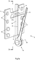
- Fig. 1 shows a view of a circuit arrangement 2, which is formed from a metal sheet 4.
- the metal sheet 4 is, for example, a copper sheet.
- connection contacts 10 for example punched as through holes or screwed or welded as bolts, can be applied.
- One or more connection contacts 12 can be provided on the output side of the first tab 6.
- the connection contacts 12 can be formed and applied in accordance with the connection contacts 10.
- One or more connection contacts 14 can be provided on the output side of the second tab 8.
- the connection contacts 14 can be formed and applied in accordance with the connection contacts 10.
- a cutting edge 16 can be provided articulated on a joint 18.
- the cutting edge 16 can be in one piece and pivoted about an axis 20 which runs parallel to the surface of the tabs 6, 8.
- a counter bearing 22 can be provided on the side of the sheet 4 opposite the cutting edge 16.
- the counter bearing can be arranged on the tabs 6, 8 in an electrically insulating manner. It is also possible for an insulation section 22a to be provided on the counter bearing 22, which electrically insulates two regions of the counter bearing 22 from one another, so that the counter bearing 22 does not form an electrical short circuit between the tabs 6, 8.
- connection contact 14 can be connected to one of the connection contacts 12 via a high-current resistor (not shown).
- the connection contacts 14, 12 facing away from one another are particularly preferred since they are at the greatest distance from one another, which enables the maximum installation space for a high-current resistor.
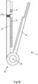
- Fig. 1b shows how the joint 18 is attached to the tab 6. Furthermore, in the Fig. 1b It can be seen that the counter bearing 22 is on one side of the tabs 6, 8 and the cutting edge 16 is arranged on the opposite side of the tabs 6, 8.
- the cutting edge 16 is lifted off the tabs 6, 8 and is preferably not in contact with it.
- the cutting edge 16 is accelerated in the direction of the tabs 6, 8 by a drive, not shown.
- the cutting edge 16 moves from bottom to top along the dividing line 24 and first shears off the tab 6 on the counter bearing 22.
- the cutting edge 16 after the tab 6 has been completely severed, meets the tab 8 at the dividing line 24.
- the cutting edge 16 then also cuts the tab 8, so that at the end of the movement of the cutting edge 16, both tabs 6, 8 are severed are.
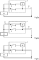
- the process can be done electrically using the 2a-c illustrate.
- the circuit arrangement 2 is provided between a high-voltage battery 30 and a load, not shown.
- An operating current 32 flows through the circuit arrangement 2.
- the tabs 6, 8 are intact.
- the current 32 flows through the tab 6 from the battery 30 to the load.
- a high-current resistor 34 is arranged in the current path of the tab 8. Due to this high-current resistor 34, the current 32 flows mainly via the tab 6.
- the cutting edge 16 first cuts through the tab 6. This leads to the current path opening via the tab 6, as in FIG Fig. 2b is shown.
- a second current path is formed over the tab 8.
- the current 32 interrupted in the first separation commutates to the second current path immediately after the separation and thus flows via the tab 8 and the high current resistor 34.
- the current 32 is considerably reduced by the high current resistor 34, for example to 10% of the original amount.
- the cutting edge 16 continues its movement, in particular its pivoting movement about the axis 20.
- the mechanical coupling of the two interruption arrangements ensures that, in a reproducible separation process, first the first tab and then the second tab is opened. This ensures that switching under load with the lowest probability of errors is guaranteed.
Landscapes
- Fuses (AREA)
Applications Claiming Priority (1)
| Application Number | Priority Date | Filing Date | Title |
|---|---|---|---|
| DE102018133197.5A DE102018133197B4 (de) | 2018-12-20 | 2018-12-20 | Schaltungsanordnung und Verfahren zum Betreiben einer solchen Schaltungsanordnung |
Publications (1)
| Publication Number | Publication Date |
|---|---|
| EP3671793A1 true EP3671793A1 (fr) | 2020-06-24 |
Family
ID=68835069
Family Applications (1)
| Application Number | Title | Priority Date | Filing Date |
|---|---|---|---|
| EP19214338.6A Withdrawn EP3671793A1 (fr) | 2018-12-20 | 2019-12-09 | Agencement de circuit |
Country Status (2)
| Country | Link |
|---|---|
| EP (1) | EP3671793A1 (fr) |
| DE (1) | DE102018133197B4 (fr) |
Citations (4)
| Publication number | Priority date | Publication date | Assignee | Title |
|---|---|---|---|---|
| EP0001059A1 (fr) * | 1977-09-13 | 1979-03-21 | Siemens Aktiengesellschaft | Disjoncteur de puissance haute tension avec résistance de commutation et dispositif commutateur auxiliaire |
| DE102014109405A1 (de) * | 2014-07-04 | 2016-01-07 | Lion Smart Gmbh | Elektrische Schaltvorrichtung für einen Energiespeicher eines Elektrofahrzeugs |
| EP2996134A1 (fr) * | 2014-09-09 | 2016-03-16 | Herakles | Coupe-circuit pyrotechnique avec amélioration de la lame de coupe |
| DE102018103018A1 (de) * | 2018-02-09 | 2018-03-29 | Peter Lell | Unterbrechungsschaltglied mit Haupt- und Nebenschlussstrompfad |
-
2018
- 2018-12-20 DE DE102018133197.5A patent/DE102018133197B4/de active Active
-
2019
- 2019-12-09 EP EP19214338.6A patent/EP3671793A1/fr not_active Withdrawn
Patent Citations (4)
| Publication number | Priority date | Publication date | Assignee | Title |
|---|---|---|---|---|
| EP0001059A1 (fr) * | 1977-09-13 | 1979-03-21 | Siemens Aktiengesellschaft | Disjoncteur de puissance haute tension avec résistance de commutation et dispositif commutateur auxiliaire |
| DE102014109405A1 (de) * | 2014-07-04 | 2016-01-07 | Lion Smart Gmbh | Elektrische Schaltvorrichtung für einen Energiespeicher eines Elektrofahrzeugs |
| EP2996134A1 (fr) * | 2014-09-09 | 2016-03-16 | Herakles | Coupe-circuit pyrotechnique avec amélioration de la lame de coupe |
| DE102018103018A1 (de) * | 2018-02-09 | 2018-03-29 | Peter Lell | Unterbrechungsschaltglied mit Haupt- und Nebenschlussstrompfad |
Also Published As
| Publication number | Publication date |
|---|---|
| DE102018133197B4 (de) | 2022-01-27 |
| DE102018133197A1 (de) | 2020-06-25 |
Similar Documents
| Publication | Publication Date | Title |
|---|---|---|
| EP3102454B1 (fr) | Réseau de bord à haute tension d'un véhicule automobile | |
| DE102012221664B4 (de) | Kurzschlussabschalter | |
| EP3701557B1 (fr) | Élément fusible électrique ainsi que procédé de fonctionnement d'un élément fusible électrique | |
| EP3046124A1 (fr) | Dispositif de protection et de commutation pour reseaux de bord haute tension | |
| EP3785285B1 (fr) | Commutateur à haute tension, alimentation de bord à haute tension dans un véhicule automobile et procédé de fonctionnement d'un commutateur à haute tension | |
| EP1192628B1 (fr) | Ensemble contact de commutation de commande d'un disjoncteur basse tension dote de contacts principaux, de contacts intermediaires et de contacts de coupure | |
| AT521150B1 (de) | Pyrotechnischer Stromtrenner | |
| EP1317761A1 (fr) | Dispositif de protection contre les surcharges | |
| DE102017205833B4 (de) | Schaltschütz-Einrichtung für ein Kraftfahrzeug, Bordnetz für ein Kraftfahrzeug und Verfahren zum Überführen einer Schaltschütz-Einrichtung von einem geschlossenen Zustand in einen geöffneten Zustand | |
| EP2932521A1 (fr) | Automate de sécurité ayant un court-circuit auxiliaire | |
| WO2021170326A1 (fr) | Dispositif de coupure, système électrique embarqué haute tension et véhicule automobile | |
| CH662903A5 (de) | Gasisolierter lasttrenner. | |
| DE102015225521B4 (de) | Vorrichtung zum Schalten eines elektrischen Stromkreises, Fahrzeug mit einer solchen Vorrichtung sowie ein Verfahren zu deren Betrieb | |
| DE102018133197B4 (de) | Schaltungsanordnung und Verfahren zum Betreiben einer solchen Schaltungsanordnung | |
| EP3716304B1 (fr) | Interrupteur électrique permettant d'interrompre une connexion à haute voltage électrique et procédé d'interruption d'une connexion à haute voltage électrique | |
| EP4179557B1 (fr) | Élément de commutation de connexion électrique | |
| EP0104599B1 (fr) | Sectionneur haute tension avec contacts préliminaires | |
| EP4167413A1 (fr) | Ensemble de commutation de coupure destiné à sécuriser un réseau de bord de véhicule | |
| EP3629352A1 (fr) | Limiteur de courant de court-circuit | |
| AT527248B1 (de) | Pyrotechnischer Stromtrenner | |
| DE102020205784A1 (de) | Schaltgerät mit Kommutierungsstrompfad | |
| AT526923B1 (de) | Pyrotechnischer Stromtrenner | |
| EP3559969A1 (fr) | Dispositif de commutation comportant deux sectionneurs et un sectionneur de puissance | |
| DE102009004758A1 (de) | Überspannungsableiter mit mindestens einem Ableitelement | |
| EP4542610A1 (fr) | Dispositif de commutation électrique d'urgence doté d'un élément de connexion pour établir une connexion électrique conductrice |
Legal Events
| Date | Code | Title | Description |
|---|---|---|---|
| PUAI | Public reference made under article 153(3) epc to a published international application that has entered the european phase |
Free format text: ORIGINAL CODE: 0009012 |
|
| STAA | Information on the status of an ep patent application or granted ep patent |
Free format text: STATUS: THE APPLICATION HAS BEEN PUBLISHED |
|
| AK | Designated contracting states |
Kind code of ref document: A1 Designated state(s): AL AT BE BG CH CY CZ DE DK EE ES FI FR GB GR HR HU IE IS IT LI LT LU LV MC MK MT NL NO PL PT RO RS SE SI SK SM TR |
|
| AX | Request for extension of the european patent |
Extension state: BA ME |
|
| STAA | Information on the status of an ep patent application or granted ep patent |
Free format text: STATUS: REQUEST FOR EXAMINATION WAS MADE |
|
| 17P | Request for examination filed |
Effective date: 20200909 |
|
| RBV | Designated contracting states (corrected) |
Designated state(s): AL AT BE BG CH CY CZ DE DK EE ES FI FR GB GR HR HU IE IS IT LI LT LU LV MC MK MT NL NO PL PT RO RS SE SI SK SM TR |
|
| STAA | Information on the status of an ep patent application or granted ep patent |
Free format text: STATUS: EXAMINATION IS IN PROGRESS |
|
| 17Q | First examination report despatched |
Effective date: 20220324 |
|
| P01 | Opt-out of the competence of the unified patent court (upc) registered |
Effective date: 20230513 |
|
| GRAP | Despatch of communication of intention to grant a patent |
Free format text: ORIGINAL CODE: EPIDOSNIGR1 |
|
| STAA | Information on the status of an ep patent application or granted ep patent |
Free format text: STATUS: GRANT OF PATENT IS INTENDED |
|
| RIC1 | Information provided on ipc code assigned before grant |
Ipc: H01H 39/00 20060101ALN20240206BHEP Ipc: H01H 9/42 20060101ALN20240206BHEP Ipc: H01H 33/16 20060101AFI20240206BHEP |
|
| INTG | Intention to grant announced |
Effective date: 20240221 |
|
| STAA | Information on the status of an ep patent application or granted ep patent |
Free format text: STATUS: THE APPLICATION IS DEEMED TO BE WITHDRAWN |
|
| 18D | Application deemed to be withdrawn |
Effective date: 20240622 |
|
| STAA | Information on the status of an ep patent application or granted ep patent |
Free format text: STATUS: GRANT OF PATENT IS INTENDED |