EP4167413A1 - Ensemble de commutation de coupure destiné à sécuriser un réseau de bord de véhicule - Google Patents
Ensemble de commutation de coupure destiné à sécuriser un réseau de bord de véhicule Download PDFInfo
- Publication number
- EP4167413A1 EP4167413A1 EP22200624.9A EP22200624A EP4167413A1 EP 4167413 A1 EP4167413 A1 EP 4167413A1 EP 22200624 A EP22200624 A EP 22200624A EP 4167413 A1 EP4167413 A1 EP 4167413A1
- Authority
- EP
- European Patent Office
- Prior art keywords
- current
- current path
- isolating
- resistor
- switch
- Prior art date
- Legal status (The legal status is an assumption and is not a legal conclusion. Google has not performed a legal analysis and makes no representation as to the accuracy of the status listed.)
- Withdrawn
Links
- 230000004044 response Effects 0.000 claims abstract description 18
- 238000000034 method Methods 0.000 claims description 16
- 229910001369 Brass Inorganic materials 0.000 claims description 8
- 239000010951 brass Substances 0.000 claims description 8
- 239000000463 material Substances 0.000 claims description 6
- 241000027294 Fusi Species 0.000 description 21
- 230000008901 benefit Effects 0.000 description 16
- 239000004065 semiconductor Substances 0.000 description 7
- 238000006243 chemical reaction Methods 0.000 description 5
- 238000010586 diagram Methods 0.000 description 5
- 230000005669 field effect Effects 0.000 description 4
- 238000005259 measurement Methods 0.000 description 4
- 238000004590 computer program Methods 0.000 description 3
- 238000000926 separation method Methods 0.000 description 3
- 230000001960 triggered effect Effects 0.000 description 3
- 238000011144 upstream manufacturing Methods 0.000 description 3
- 238000002955 isolation Methods 0.000 description 2
- 230000000712 assembly Effects 0.000 description 1
- 238000000429 assembly Methods 0.000 description 1
- 230000000903 blocking effect Effects 0.000 description 1
- 230000008878 coupling Effects 0.000 description 1
- 238000010168 coupling process Methods 0.000 description 1
- 238000005859 coupling reaction Methods 0.000 description 1
- 230000001186 cumulative effect Effects 0.000 description 1
- 230000001419 dependent effect Effects 0.000 description 1
- 238000011161 development Methods 0.000 description 1
- 230000018109 developmental process Effects 0.000 description 1
- 230000000694 effects Effects 0.000 description 1
- 230000005611 electricity Effects 0.000 description 1
- 238000005516 engineering process Methods 0.000 description 1
- 238000010438 heat treatment Methods 0.000 description 1
- 239000011810 insulating material Substances 0.000 description 1
- 239000002184 metal Substances 0.000 description 1
- 239000000203 mixture Substances 0.000 description 1
- 230000008092 positive effect Effects 0.000 description 1
- 230000008569 process Effects 0.000 description 1
- WQGWDDDVZFFDIG-UHFFFAOYSA-N pyrogallol Chemical compound OC1=CC=CC(O)=C1O WQGWDDDVZFFDIG-UHFFFAOYSA-N 0.000 description 1
- 238000003466 welding Methods 0.000 description 1
Images


Classifications
-
- H—ELECTRICITY
- H02—GENERATION; CONVERSION OR DISTRIBUTION OF ELECTRIC POWER
- H02H—EMERGENCY PROTECTIVE CIRCUIT ARRANGEMENTS
- H02H3/00—Emergency protective circuit arrangements for automatic disconnection directly responsive to an undesired change from normal electric working condition with or without subsequent reconnection ; integrated protection
- H02H3/02—Details
- H02H3/025—Disconnection after limiting, e.g. when limiting is not sufficient or for facilitating disconnection
-
- H—ELECTRICITY
- H02—GENERATION; CONVERSION OR DISTRIBUTION OF ELECTRIC POWER
- H02H—EMERGENCY PROTECTIVE CIRCUIT ARRANGEMENTS
- H02H7/00—Emergency protective circuit arrangements specially adapted for specific types of electric machines or apparatus or for sectionalised protection of cable or line systems, and effecting automatic switching in the event of an undesired change from normal working conditions
- H02H7/26—Sectionalised protection of cable or line systems, e.g. for disconnecting a section on which a short-circuit, earth fault, or arc discharge has occured
- H02H7/268—Sectionalised protection of cable or line systems, e.g. for disconnecting a section on which a short-circuit, earth fault, or arc discharge has occured for DC systems
-
- H—ELECTRICITY
- H02—GENERATION; CONVERSION OR DISTRIBUTION OF ELECTRIC POWER
- H02H—EMERGENCY PROTECTIVE CIRCUIT ARRANGEMENTS
- H02H9/00—Emergency protective circuit arrangements for limiting excess current or voltage without disconnection
- H02H9/02—Emergency protective circuit arrangements for limiting excess current or voltage without disconnection responsive to excess current
Definitions
- the present invention relates to an isolating switching arrangement for protecting a vehicle electrical system to protect against a short circuit in one or more paths of a current distributor connected to the vehicle electrical system, and a corresponding method.
- the disclosure relates to a FUSI (Functional Safety) circuit breaker with current limitation.
- the selectivity cannot be ensured in an efficient manner, which means that in the event of a short circuit in a subordinate current path, such as that of the auxiliary heater, the fuse of the auxiliary heater blows and not a fuse in one superordinate main distributor.
- a subordinate current path such as that of the auxiliary heater
- the fuse in the higher-level main distributor is triggered, other (safety-critical) consumers are also disconnected from the supply.
- Selectivity down to the level of a single current path cannot be implemented in the vehicle electrical system current distributors available today.
- the electronic FUSI circuit breakers currently available do not have a current limitation stage, only quick disconnection in the event of undervoltage. In the event of a short circuit, the underlying power distributor is completely discarded without the fuse being able to trip.
- One object of the invention is therefore to create an advantageous concept for the design of power distributors in the vehicle electrical system that meet the FUSI requirements for an uninterrupted and safe power supply, in particular a concept with which 1) the freedom from feedback and 2) the selectivity in Vehicle electrical system can be ensured in an efficient manner according to the FUSI requirements.
- the inventive solution is based on the idea of equipping a FUSI circuit breaker with a current-limiting resistor and connecting it upstream of a power distributor with fuses.
- the resistor limits the current to less than 350A, for example, in the event of a subordinate short circuit.
- the fuse is then triggered with this 350A. Without this current limitation, the short-circuit current would be greater than 1000A before the fuse trips, with a very high repercussion in the vehicle electrical system.
- the inventive solution allows a hybrid structure with a mixture of conventional fuses and electronic FUSI protection.
- the innovative solution is so Can be implemented more cost-optimally than purely electronic protection. Nevertheless, the freedom from feedback can be implemented for FUSI.
- a power distributor is a device or an arrangement, e.g. on a printed circuit board, in which fuse and switching elements for the distribution of electrical energy are housed, primarily in the area of the low-voltage network or vehicle on-board network. It is in practically every motor vehicle. Electrical lines run from power distributors either directly to the points of consumption, for example to the sensors, the fan or the interior lighting in the vehicle, or to the next subordinate power distributor.
- An isolating switching arrangement is an arrangement of electrical and/or electronic switches, as part of an electronic circuit, which implements the function of potential isolation between two or more sections of the electronic circuit, for example in the event of a short circuit in one section of the electronic circuit, to prevent a harmful reaction to the to prevent other sections of the electronic circuit.
- a separating element within the meaning of this disclosure is a switch, in particular an electronic switch, which implements the potential separation between the two or more sections of the electronic circuit.
- Such an electronic switch also known as an analog switch or semiconductor switch, is part of an electronic circuit that implements the function of an electromechanical switch.
- Field effect transistors FET
- bipolar transistors e.g. IGBTs (bipolar transistors with insulated gate electrodes)
- diodes can be used as switching elements or isolating elements.
- thyristors and semiconductor relays can also be used as electronic switches.
- MOSFET metal-oxide-semiconductor field effect transistor
- IGBT IGBTs
- a metal-oxide-semiconductor field effect transistor is one of the field effect transistors with an insulated gate and is a type of transistor that is defined by a stack of layers made up of a metal gate electrode, a semiconductor and the oxidic dielectric in between. Controlling the flow of electricity in semiconductors between the two electrical connections drain and source takes place via a control voltage at a third connection, the so-called gate.
- IGBTs are an evolution of the vertical power MOSFET.
- a bipolar transistor with an insulated gate electrode is a semiconductor component that is used in power electronics because it combines the advantages of the bipolar transistor (good conduction behavior, high blocking voltage, robustness) and the advantages of the field effect transistor (almost powerless control).
- Functional safety describes that part of the safety of a system that depends on the correct functioning of the safety-related system and other risk-reducing measures.
- functional safety is usually described in the form of ASIL ("Automotive Safety Integrity Level") classes.
- ASIL Automotive Safety Integrity Level
- the ASIL classification is composed of various factors, these are 1) "Severity - S” according to the severity of the fault, the hazard to the user or the environment; 2) “Exposure - E” according to the probability of occurrence, ie frequency and/or duration of the operating condition; 3) "Controllability - C" according to the controllability of the error.
- ASIL A recommended failure probability of less than 10-6 / hour
- ASIL B recommended probability of failure less than 10 -7 / hour
- ASIL C required probability of failure less than 10 -7 / hour
- ASIL D required probability of failure less than 10 -8 / hour.
- fuses for extinguishing overload currents, in particular fuses.
- the electrical fuse or overcurrent fuse interrupts an electrical circuit when the electrical current exceeds a specified current level for a predetermined time.
- overcurrent fuses such as the fuse, the circuit breaker or the pyro fuse.
- a circuit breaker arrangement for protecting a vehicle electrical system against a short circuit in one or more paths of a current distributor connected to the vehicle electrical system
- the circuit breaker arrangement comprising the following: a parallel circuit composed of a first current path and a second current path, which can be switched between a battery connection of the vehicle electrical system and the current distributor, the first current path comprising a first switch with at least one isolating element, which is designed to respond to an exceeding when the current rises in the current distributor a first current threshold to disconnect the first current path; wherein the second current path comprises a resistor configured to limit a current increase in the second current path to a second current threshold.
- the circuit breaker arrangement thus creates an advantageous design of power distributors in the vehicle electrical system that meet the FUSI requirements for an uninterrupted and reliable power supply. With the circuit breaker arrangement, these power distributors meet the FUSI requirements for freedom from feedback and selectivity in the vehicle electrical system.
- the short-circuit current can be limited in an advantageous manner.
- the resistor limits the current to the second current threshold value of, for example, 350 A or below.
- the fuse can then be tripped with this second current threshold value of e.g. 350A.
- the short-circuit current would be much higher until the fuse trips, e.g. greater than 1000A and would have a very high repercussion in the vehicle electrical system.
- the second current threshold value is matched to a tripping current of a fuse in one of the paths of the current distributor in order to blow the fuse when a current in the second current path of the isolating switching arrangement increases to the second current threshold value.
- the resistor limits the rise in current to the second current threshold value, which corresponds to the tripping current of the fuse. Ie the fuse in the short-circuit path triggers and thus extinguishes the short-circuit current. The path in which the short circuit occurred is selectively switched off without having to shut down an entire main distributor.
- the second current path of the isolating switch arrangement comprises a second switch with at least one isolating element, the second switch being arranged in series with the resistor.
- the second switch (together with the first switch) can completely disconnect the current distributor from the battery connection. This can be advantageous if, e.g. in the event of a vehicle crash, there are multiple short circuits in different paths of the current distributor, which the resistance can no longer limit.
- the isolating switch arrangement can also be used here as a terminal switch.
- the at least one isolating element of the second switch is designed to isolate the second current path of the isolating switch arrangement in response to an overload of the resistor.
- the second switch can completely disconnect the current distributor from the battery connection.
- the short circuit current is divided between the two short circuit paths (first current path and second current path). Triggering then takes a very long time, so that the resistor is overloaded. In this case, too, rapid and reliable separation can be carried out with the isolating switching arrangement.
- the second switch is designed to work together with the first switch to completely disconnect the current distributor from the battery connection of the vehicle electrical system.
- the at least one isolating element of the second switch is designed as a MOSFET or IGBT transistor.
- the second current path of the isolating switch arrangement comprises a fuse which is arranged in series with the resistor.
- the fuse is designed to disconnect the second current path of the isolating switch arrangement in response to an overload of the resistor.
- the fuse is thermally coupled to the resistor in order to detect the overload of the resistor.
- the fuse is designed to trigger when the temperature of the resistor rises in response to a temperature threshold value being exceeded in order to disconnect the second current path.
- the fuse can trip quickly and reliably when its predetermined temperature threshold value is reached, for example it can melt in order to keep the safety-critical vehicle components away from the short circuit.
- the fuse is designed to disconnect the second current path when the current rises in the second current path in response to a fourth current threshold value being exceeded, the fourth current threshold value being at least one order of magnitude above the second current threshold value.
- the fuse can completely disconnect the current distributor from the battery connection if, for example, a multiple short circuit occurs in which the current through the second current path is one or more orders of magnitude above the second current threshold value of the current limitation by the resistor.
- the at least one isolating element of the first switch is designed as a MOSFET or IGBT transistor.
- the resistor is made of a brass material.
- the resistor has a meandering configuration and is embedded in a plastic housing.
- the resistor can be designed to be space-saving and robust, and the heat can be dissipated to the outside via the plastic housing.
- the object is achieved by a method for protecting a vehicle electrical system of a vehicle against a short circuit in one or several paths of a power distributor connected to the vehicle electrical system by means of an isolating switching arrangement which is connected between a battery connection of the vehicle electrical system and the power distributor, the isolating switching arrangement comprising a parallel connection of a first current path and a second current path, the first current path having a first switch with at least one separating element, and wherein the second current path comprises a resistor, the method comprising: separating the first current path by means of the at least one separating element of the first switch in the event of a current rise in the current distributor in response to a first current threshold value being exceeded; and limiting a current rise in the second current path to a second current threshold using the resistor in the second current path.
- Such a method thus creates an advantageous design of current distributors in the vehicle electrical system that meet the FUSI requirements for an uninterrupted and safe power supply, in particular in accordance with the requirements for freedom from reactions and selectivity in the vehicle electrical system.
- the method can be used to limit the short-circuit current in an advantageous manner.
- the resistor limits the current to the second current threshold value of, for example, 350 A or below.
- the fuse can then be tripped with this second current threshold value of e.g. 350A. Without this current limitation, the short-circuit current would be much higher until the fuse trips, e.g. greater than 1000A and would have a very high repercussion in the vehicle electrical system.
- the object is achieved by a computer program with a program code for executing the method according to the second aspect on a controller, in particular on a microcontroller and/or an ASIC.
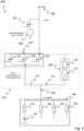
- FIG. 1 shows a circuit diagram of a vehicle electrical system 100 with an isolating switch arrangement 110 according to a first specific embodiment.
- the isolating switching arrangement 110 serves to protect the vehicle electrical system 100 against a short circuit 101 in one or more paths of a power distributor 140 connected to the vehicle electrical system 100.
- the isolating switching arrangement 110 includes a parallel circuit made up of a first current path 111 and a second current path 112 which can be connected between a battery connection 160 of the vehicle electrical system 100 and the current distributor 140 .
- the first current path 111 comprises a first switch 120 with at least one isolating element 121 which is designed to isolate the first current path 111 when the current in the current distributor 140 rises in response to a first current threshold value being exceeded.
- the current in the current distributor 140 can be determined, for example, based on a measurement at the measuring point 102 .
- the second current path 112 includes a resistor 113 which is designed to limit a current increase in the second current path 112 to a second current threshold value.
- the first switch 120 can be implemented as a first transistor bank TB1, for example.
- a first transistor bank TB1 comprises one or more isolating elements 121, 122, 123.
- FIG 1 an exemplary number of three transistors 121, 122, 123 is shown. The number of transistors is matched to a required current carrying capacity of the first transistor bank TB1.
- the second current threshold value is matched, for example, to a tripping current of a fuse 141 in one of the paths of the current distributor 140 in order to trip the fuse 141 when a current in the second current path of the isolating switching arrangement 110 rises to the second current threshold value.
- the second current path 112 of the isolating switching arrangement 110 can include a second switch 130 with at least one isolating element 131, as in FIG figure 1 shown with the second switch 130 in series with the resistor 113 .
- the second switch 130 can be implemented as a second transistor bank TB2, for example.
- a second transistor bank TB2 comprises one or more isolating elements 131, 132.
- FIG 1 an exemplary number of two transistors 131, 132 is shown as isolating elements. The number of transistors is matched to a required current carrying capacity of the second transistor bank TB2.
- the at least one isolating element 131 of the second switch 130 is designed to prevent thermal overloading of the resistor 113, e.g. due to simultaneous short circuits in a number of load paths, by switching off.
- the second switch 130 is designed to work together with the first switch 120 to completely disconnect the power distributor 140 from the battery connection 160 of the vehicle electrical system 100 .
- both switches 120, 130 can be driven with one control signal to disconnect.
- the at least one isolating element 131 of the second switch 130 can be in the form of a MOSFET or IGBT transistor, for example.
- the at least one isolating element 121 of the first switch 120 can also be in the form of a MOSFET or IGBT transistor, for example.
- the resistor 113 can be made of a brass material, for example. In one embodiment, the resistor 113 can be configured in a meandering fashion, as shown below, for example figure 3 shown. The resistor 113 can also be embedded in a plastic housing.
- the mode of operation of the isolating switch arrangement 110 is to be described in more detail below.
- the circuit breaker assembly 110 is also referred to herein as a current-limiting FUSI circuit breaker.
- FUSI circuit breaker For example, it can be connected to a conventional power distributor 140, as shown in figure 1 shown.
- transistor banks TB1 and TB2 are conductive. If a short circuit 101 now occurs in a load in a path of the current distributor 140 and the current in the current distributor 140 rises above e.g. 350A (corresponding to the first current threshold value mentioned above), transistor bank TB1 opens. The control can take place via a current measurement with a current threshold, e.g. at measuring point 102. The current then flows via the transistor bank TB2 and the resistor 113, which can be 30mOhm, for example. The resistor 113 then limits the current to approximately 300A (corresponding to the second current threshold mentioned above).
- Transistor bank TB2 has the following purposes: 1) If FUSI switch 110 is also used as a clamp switch, then full isolation can be done across TB2. 2)
- resistor 113 can no longer carry the short circuit currents that occur and overheats. In this case, TB2 separates.
- the resistor 113 can be made of a brass material. On the one hand, this allows a sufficiently large resistance of e.g. 30mOhm to be implemented, and on the other hand, enough thermal mass to keep the temperature sufficiently low.
- a meander stamped out of CUZN37 brass, 600mm long, 2mm wide and 1mm thick, can convert the 400J with a temperature swing of 70K and a resistance of 30mOhm.
- the current distributors 140 in the vehicle electrical system can be designed in such a way that they meet the FUSI requirements for an uninterruptible and reliable power supply. This means that the requirements for the two essential points for functional safety, namely non-reaction and selectivity, are ensured.
- the isolating switching arrangement 110 can be used to ensure in an efficient manner that a short circuit in a subordinate electrical component does not lead to a voltage drop in the vehicle electrical system 100, and thus safety-critical systems, such as an electric power steering (EPS) 150, switch off due to undervoltage.
- EPS electric power steering
- EPS electric power steering
- the EPS has an electric motor that controls the vehicle steering. With the electric motor, the EPS controls and supports the vehicle steering and ensures an optimal and pleasant steering feel. Together with the circuit breaker arrangement 110, the EPS enables highly automated driving with maximum safety up to SAE level 4.
- the selectivity can be ensured in an efficient manner with the isolating switching arrangement 110 .
- a short circuit 101 in a subordinate current path such as that of the auxiliary heater, it is ensured that the fuse 141 of the auxiliary heater triggers and not a fuse in a higher-level main distributor. This allows selectivity down to the level of a single current path.
- FIG. 2 shows a circuit diagram of a vehicle electrical system 200 with an isolating switch arrangement 210 according to a second specific embodiment.
- the isolating switch arrangement 210 is designed similarly to the isolating switch arrangement 110 according to the first embodiment, except that no second switch 130 is implemented in the second current path 112 , but rather a fuse 114 which is connected in series with the resistor 113 .
- the isolating switching arrangement 210 serves to protect the vehicle electrical system 200 against a short circuit 101 in one or more paths of a power distributor 140 connected to the vehicle electrical system 200.
- the isolating switching arrangement 210 includes a parallel circuit made up of a first current path 111 and a second current path 112 which can be connected between a battery connection 160 of the vehicle electrical system 200 and the current distributor 140 .
- the first current path 111 includes a first switch 120 with at least one isolating element 121, as above figure 1 described, which is designed to disconnect the first current path 111 when the current rises in the current distributor 140 in response to a first current threshold value being exceeded.
- the current in the current distributor 140 can be determined, for example, based on a measurement at the measuring point 102 .
- the second current path 112 comprises a resistor 113 which is designed to limit a current increase in the second current path 112 to a second current threshold value, as described above figure 1 described.
- the first switch 120 can be implemented, for example, as a first transistor bank TB1, as per above figure 1 described.
- the second current threshold value is matched, for example, to a tripping current of a fuse 141 in one of the paths of the current distributor 140 in order to trip the fuse 141 when a current in the second current path of the isolating switching arrangement 110 rises to the second current threshold value.
- the second current path 112 of the isolating switching arrangement 210 includes a fuse 114 which is arranged in series with the resistor 113 .
- the fuse 114 is designed to disconnect the second current path 112 of the isolating switching arrangement 210 in response to an overload of the resistor 113 .
- Fuse 114 may be thermally coupled to resistor 113 to detect overloading of resistor 113 .
- the fuse 114 can be designed, for example, to trigger when the temperature of the resistor 113 rises in response to a temperature threshold value being exceeded, in order to disconnect the second current path 112 .
- the fuse 114 can be designed, for example, to disconnect the second current path 112 in the event of a current rise in the second current path in response to a fourth current threshold value being exceeded.
- the fourth current threshold value can, for example, be at least one order of magnitude above the second current threshold value. An order of magnitude can denote a factor of 2 here.
- the at least one isolating element 121 of the first switch 120 can be in the form of a MOSFET or IGBT transistor, for example.
- the resistor 113 can be made of a brass material, for example.
- the resistor 113 can be configured in a meandering shape, as shown below, for example figure 3 shown.
- the resistor 113 can also be embedded in a plastic housing.
- FIG. 12 shows a second embodiment of the FUSI circuit breaker 210 without the transistor bank TB2 as related to the first embodiment above figure 1 described. This was replaced by a fuse 114, for example a 250A fuse (corresponding to the fourth current threshold value shown above) with thermal coupling to the resistor 113. If the resistor 113 is overloaded by multiple short circuits, the triggering of the 250 A fuse 114 is thus accelerated by the resistor 113 heating up.
- a fuse 114 for example a 250A fuse (corresponding to the fourth current threshold value shown above) with thermal coupling to the resistor 113. If the resistor 113 is overloaded by multiple short circuits, the triggering of the 250 A fuse 114 is thus accelerated by the resistor 113 heating up.
- FIG. 3 shows a schematic representation of a resistor 113 for current limitation in a circuit breaker arrangement 110, 210 according to the first or second embodiment.
- the resistor 113 has a meandering configuration and can be made of a brass material, for example.
- the resistor 113 can also be embedded in a plastic housing.
- the envelope may be approximately 45mm x 40mm.
- the ends can be angled and formed into contact lugs.
- the resistance meander 113 can be injected into a housing so that only the contact lugs protrude from the insulating material.
- the circuit board with the electronic circuit, which implements the isolating switch arrangement 110, 210, can have two lamellar contacts, for example. In this way, the circuit board can be plugged onto the housing part with the injected resistance meander 113 .
- the resistor 113 can be wound over a brass wire made of CuZn37.
- the wire can then be connected to the circuit board by laser welding, for example.
- FIG. 4 shows a schematic representation of the tripping current 400 of a 60A fuse without current limitation 401 and with current limitation 402.
- the current-limiting circuit breaker 110 only needs to be able to handle approximately 350A versus 1000A and more for a non-current-limiting circuit breaker. This has a positive effect on the cost of the isolating switch 110.
- the isolating switch 110 can be made simpler, so that a smaller number of transistors 121, 122, 123 connected in parallel are sufficient to carry the current.
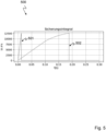
- figure 5 shows a schematic representation of the fuse integral 500 of the 60A fuse without current limitation 501 and with current limitation 502.
- the current-limiting fuse 502 takes longer to blow than the non-current-limiting fuse 501.
- the current-limited fuse 502 takes about 180ms, while the non-current-limited fuse 501 blows after about 20ms.
- FIG. 6 shows a schematic representation of the voltage curve 600 of the vehicle electrical system with a switch disconnector arrangement without current limitation 601 and with current limitation 602.
- FIG. 7 shows a schematic representation of the voltage curve 700 at the current distributor 140 in a switch disconnector arrangement without current limitation 701 and with current limitation 702.
- FIG. 8 shows a schematic representation of a method 800 for securing a vehicle electrical system according to the disclosure.
- the method 800 is used to protect a vehicle electrical system 100, 200, as above for figures 1 and 2 shown, against a short circuit 101 in one or more paths of a power distributor 140 connected to the vehicle electrical system 100, 200 by means of a disconnecting switching arrangement 110, 210, as per the above figures 1 and 2 described.
- the isolating switching arrangement 110, 210 is connected between a battery connection 160 of the vehicle electrical system 100, 200 and the power distributor 140, as described above figures 1 and 2 shown.
- the isolating switching arrangement 110, 210 comprises a parallel connection of a first current path 111 and a second current path 112, the first current path 111 comprising a first switch 120 having at least one isolating element 121, and the second current path 112 comprising a resistor 113, as described above for the figures 1 and 2 described.
- the procedure includes the following steps: Disconnecting 801 the first current path 111 by means of the at least one disconnecting element 121 of the first switch 120 when the current rises in the current distributor 140 in response to a first current threshold value being exceeded, such as, for example, to the above figures 1 and 2 described; and
- Limiting 802 a current increase in the second current path 112 to a second current threshold value by means of the resistor 113 in the second current path 112, such as, for example, to the above figures 1 and 2 described.
- a computer program with a program code for executing the method 800 on a controller eg a microprocessor or an ASIC, can be provided.
Landscapes
- Emergency Protection Circuit Devices (AREA)
Applications Claiming Priority (1)
| Application Number | Priority Date | Filing Date | Title |
|---|---|---|---|
| DE102021126909.1A DE102021126909A1 (de) | 2021-10-18 | 2021-10-18 | Trennschaltanordnung zur absicherung eines fahrzeug-bordnetzes |
Publications (1)
| Publication Number | Publication Date |
|---|---|
| EP4167413A1 true EP4167413A1 (fr) | 2023-04-19 |
Family
ID=83689857
Family Applications (1)
| Application Number | Title | Priority Date | Filing Date |
|---|---|---|---|
| EP22200624.9A Withdrawn EP4167413A1 (fr) | 2021-10-18 | 2022-10-10 | Ensemble de commutation de coupure destiné à sécuriser un réseau de bord de véhicule |
Country Status (3)
| Country | Link |
|---|---|
| EP (1) | EP4167413A1 (fr) |
| CN (1) | CN115991156A (fr) |
| DE (1) | DE102021126909A1 (fr) |
Families Citing this family (1)
| Publication number | Priority date | Publication date | Assignee | Title |
|---|---|---|---|---|
| EP4624265A1 (fr) * | 2024-03-28 | 2025-10-01 | Lisa Dräxlmaier GmbH | Dispositif de distribution de courant électronique et procédé de fonctionnement d'un tel dispositif de distribution de courant |
Citations (4)
| Publication number | Priority date | Publication date | Assignee | Title |
|---|---|---|---|---|
| US20110317321A1 (en) * | 2009-02-06 | 2011-12-29 | Siemens Aktiengesellschaft | Short circuit protection device and switchgear assembly having such protection devices |
| DE102010038892A1 (de) * | 2010-08-04 | 2012-02-09 | Robert Bosch Gmbh | Verfahren zur Begrenzung eines Einschaltstromes in einem elektrischen Netz |
| DE102018212507A1 (de) * | 2018-07-26 | 2020-01-30 | Robert Bosch Gmbh | Elektronischer Leistungsverteiler |
| US20200031240A1 (en) * | 2018-07-25 | 2020-01-30 | Volkswagen Aktiengesellschaft | Traction network and method for operating a traction network of an electrically-driven transportation vehicle in the event of a short circuit |
Family Cites Families (6)
| Publication number | Priority date | Publication date | Assignee | Title |
|---|---|---|---|---|
| JP5825107B2 (ja) | 2012-01-11 | 2015-12-02 | スズキ株式会社 | 車両用電源装置 |
| CA3006536A1 (fr) * | 2015-11-24 | 2017-06-01 | New Energy Corporation Inc. | Systeme mobile de production et de conditionnement d'energie electrique |
| EP3420575B1 (fr) | 2016-02-24 | 2020-08-12 | Lisa Dräxlmaier GmbH | Dispositif électrique de sécurité |
| DE102016115823B4 (de) * | 2016-08-25 | 2023-01-05 | Auto-Kabel Management Gmbh | Kraftfahrzeugbordnetz sowie Kraftfahrzeug mit einem Kraftfahrzeugbordnetz |
| DE102018208754A1 (de) * | 2018-06-04 | 2019-12-05 | Volkswagen Aktiengesellschaft | Kraftfahrzeugbordnetz, Verfahren zum Betreiben eines derartigen Kraftfahrzeugbordnetzes sowie Sicherungsvorrichtung für ein Kraftfahrzeugbordnetz |
| DE102019007956A1 (de) | 2019-10-24 | 2021-04-29 | Daimler Ag | Elektronisches Spannungsversorgungssystem |
-
2021
- 2021-10-18 DE DE102021126909.1A patent/DE102021126909A1/de not_active Withdrawn
-
2022
- 2022-10-10 EP EP22200624.9A patent/EP4167413A1/fr not_active Withdrawn
- 2022-10-13 CN CN202211252907.8A patent/CN115991156A/zh active Pending
Patent Citations (4)
| Publication number | Priority date | Publication date | Assignee | Title |
|---|---|---|---|---|
| US20110317321A1 (en) * | 2009-02-06 | 2011-12-29 | Siemens Aktiengesellschaft | Short circuit protection device and switchgear assembly having such protection devices |
| DE102010038892A1 (de) * | 2010-08-04 | 2012-02-09 | Robert Bosch Gmbh | Verfahren zur Begrenzung eines Einschaltstromes in einem elektrischen Netz |
| US20200031240A1 (en) * | 2018-07-25 | 2020-01-30 | Volkswagen Aktiengesellschaft | Traction network and method for operating a traction network of an electrically-driven transportation vehicle in the event of a short circuit |
| DE102018212507A1 (de) * | 2018-07-26 | 2020-01-30 | Robert Bosch Gmbh | Elektronischer Leistungsverteiler |
Also Published As
| Publication number | Publication date |
|---|---|
| CN115991156A (zh) | 2023-04-21 |
| DE102021126909A1 (de) | 2023-04-20 |
Similar Documents
| Publication | Publication Date | Title |
|---|---|---|
| EP1186084B1 (fr) | Dispositif de coupure electrique pour la protection contre les surintensites | |
| DE102016107707B3 (de) | Schutzvorrichtung für eine Hochvolt-Spannungsversorgung | |
| DE102016219098B4 (de) | Batterie-Trenneinrichtung | |
| WO2016015954A1 (fr) | Dispositif servant à surveiller la présence éventuelle d'une surcharge dans un réseau de bord à haute tension d'un véhicule à fonctionnement électrique | |
| DE102016216331B3 (de) | Trennvorrichtung zur Stromunterbrechung, Schutzschalter mit einem Sensor und einer Trennvorrichtung sowie Verfahren zum Betrieb einer Trennvorrichtung | |
| DE102009023801A1 (de) | Sicherungsvorrichtung mit pyrotechnischer Sicherung | |
| DE102015107718B4 (de) | Vorrichtung und Verfahren zum Absichern einer Bordnetz-Komponente eines Fahrzeug-Bordnetzes | |
| EP3300252A2 (fr) | Système de coupure de courant, système de batterie, organe de commande et procédé de séparation d'un flux de courant entre une batterie et un consommateur de la batterie | |
| EP2932521B1 (fr) | Automate de sécurité ayant un court-circuit auxiliaire | |
| DE112022002357T5 (de) | Fahrzeugseitig angeordnete umschaltvorrichtung | |
| EP1004131A2 (fr) | Element fusible pour installations electriques | |
| EP4075618A1 (fr) | Circuit d'isolation destiné à l'isolation galvanique réversible d'un consommateur d'une source de tension continue | |
| DE102013012578B4 (de) | Vorrichtung zum Absichern einer elektrischen Leitung sowie Verfahren zum Betreiben einer auf einer elektrischen Leitung angeordneten Vorrichtung | |
| EP4167413A1 (fr) | Ensemble de commutation de coupure destiné à sécuriser un réseau de bord de véhicule | |
| EP3762953B1 (fr) | Dispositif de séparation pour l'interruption d'un courant continu d'un trajet de courant, et réseau de bord d'un véhicule à moteur | |
| WO2017102171A1 (fr) | Dispositif de commutation d'un circuit électrique | |
| EP2672595B1 (fr) | Agencement de circuit et procédé destinés à la coupure du courant continu | |
| DE102020005248A1 (de) | Verfahren zum Betreiben eines Hochvolt-Energiespeichersystems | |
| EP3925835B1 (fr) | Réseau embarqué pour un véhicule | |
| DE19827374A1 (de) | Sicherungselement für elektrische Anlagen | |
| DE10132750A1 (de) | Siecherungsanordnung für eine elektrische Leitung in einem Fahrzeug | |
| DE102017212156B4 (de) | Elektrisches Versorgungsnetz sowie Verfahren zum Betrieb eines elektrischen Versorgungsnetzes | |
| LU506789B1 (de) | Elektronische Sicherung zum Vermeiden eines unerwünschten dauerhaften Abschaltens von elektrischen Verbrauchern bei Überlastverhalten | |
| LU505555B1 (de) | Trennschalter | |
| EP0504463A1 (fr) | Circuit pour alimentation en courant |
Legal Events
| Date | Code | Title | Description |
|---|---|---|---|
| PUAI | Public reference made under article 153(3) epc to a published international application that has entered the european phase |
Free format text: ORIGINAL CODE: 0009012 |
|
| STAA | Information on the status of an ep patent application or granted ep patent |
Free format text: STATUS: THE APPLICATION HAS BEEN PUBLISHED |
|
| AK | Designated contracting states |
Kind code of ref document: A1 Designated state(s): AL AT BE BG CH CY CZ DE DK EE ES FI FR GB GR HR HU IE IS IT LI LT LU LV MC ME MK MT NL NO PL PT RO RS SE SI SK SM TR |
|
| STAA | Information on the status of an ep patent application or granted ep patent |
Free format text: STATUS: THE APPLICATION HAS BEEN WITHDRAWN |
|
| 18W | Application withdrawn |
Effective date: 20230504 |