EP3673761A1 - Element eines langlauf-skischuhs, das durch koinjektion hergestellt wird - Google Patents
Element eines langlauf-skischuhs, das durch koinjektion hergestellt wird Download PDFInfo
- Publication number
- EP3673761A1 EP3673761A1 EP18425107.2A EP18425107A EP3673761A1 EP 3673761 A1 EP3673761 A1 EP 3673761A1 EP 18425107 A EP18425107 A EP 18425107A EP 3673761 A1 EP3673761 A1 EP 3673761A1
- Authority
- EP
- European Patent Office
- Prior art keywords
- zone
- cross
- plastic material
- country ski
- ski boot
- Prior art date
- Legal status (The legal status is an assumption and is not a legal conclusion. Google has not performed a legal analysis and makes no representation as to the accuracy of the status listed.)
- Granted
Links
Images

Classifications
-
- A—HUMAN NECESSITIES
- A43—FOOTWEAR
- A43B—CHARACTERISTIC FEATURES OF FOOTWEAR; PARTS OF FOOTWEAR
- A43B5/00—Footwear for sporting purposes
- A43B5/04—Ski or like boots
- A43B5/0411—Ski or like boots for cross-country
-
- A—HUMAN NECESSITIES
- A43—FOOTWEAR
- A43B—CHARACTERISTIC FEATURES OF FOOTWEAR; PARTS OF FOOTWEAR
- A43B23/00—Uppers; Boot legs; Stiffeners; Other single parts of footwear
- A43B23/08—Heel stiffeners; Toe stiffeners
- A43B23/16—Heel stiffeners; Toe stiffeners made of impregnated fabrics, plastics or the like
- A43B23/17—Heel stiffeners; Toe stiffeners made of impregnated fabrics, plastics or the like made of plastics
-
- A—HUMAN NECESSITIES
- A43—FOOTWEAR
- A43B—CHARACTERISTIC FEATURES OF FOOTWEAR; PARTS OF FOOTWEAR
- A43B5/00—Footwear for sporting purposes
- A43B5/04—Ski or like boots
- A43B5/0427—Ski or like boots characterised by type or construction details
- A43B5/0482—Ski or like boots characterised by type or construction details made from materials with different rigidities
Definitions
- the present invention relates to a cross-country ski boot element made by plastic injection.
- the invention also relates to a cross-country ski boot comprising at least one such element.
- the invention also relates to a method of manufacturing a cross-country ski boot element.
- Cross-country skiing is a sport in which a practitioner progresses on snowy, flat or hilly terrain, thanks to his own impulses and by means of cross-country skis.
- Cross-country skis are long and narrow tips. They do not have metal edges and are fixed only at the front of the foot.
- Cross-country skiing can be practiced according to two techniques: the traditional technique, known as “classic” or “alternative step”, which consists of advancing while keeping the two skis parallel, and the technique of “no skater”, or “skating » Whose style on the legs can be compared to roller skating or ice skating.
- cross-country skiing For the practice of cross-country skiing, specific shoes are used. The sole of these shoes has in particular a means of attachment at the front, for fixing the boot to a cross-country ski according to a rotational connection. The impulses are transmitted from the practitioner's legs and feet to the ski through the shoes.
- Cross-country ski boots must therefore include a high degree of rigidity in order to effectively transmit the efforts of the practitioner towards skiing.
- significant rigidity can cause discomfort for the user, in particular when certain parts of the foot or of the lower leg bear on excessively hard parts of the shoe.
- the integration of stiffness elements in a cross-country ski boot increases its weight, which tires the user more quickly.
- a cross-country ski boot must also include other mechanical properties such as good impact resistance, the ability to thermoform, that is to say to deform under the effect of a source of heat to match the shape of the foot.
- the design of a cross-country ski boot is the subject of many compromises between comfort, performance and reasonable manufacturing costs.
- the object of the invention is to provide a cross-country ski boot element overcoming the above drawbacks and improving the cross-country ski boots known from the prior art.
- a first object of the invention is a cross-country ski boot element allowing optimal transmission of the forces exerted by the practitioner.
- a second object of the invention is a cross-country ski boot element making it possible to manufacture a comfortable, robust and economical cross-country ski boot.
- the cross-country ski boot element comprises an inner side part and an outer side part, a first zone, a second zone and a third zone.
- the first zone comprises two plastic materials co-injected in its thickness, the first plastic material of the first zone forming two layers of the wall constituting internal and external faces of said wall, and the second plastic material of the first zone being interposed between the two layers of the first plastic material of the first zone.
- the second zone comprises either two plastic materials co-injected in its thickness, the first plastic material of the second zone forming two layers of the wall constituting internal and external faces of said wall, and the second plastic material of the second zone being interposed between the two layers of the first plastic material of the second zone, or the second zone comprises a single plastic material.
- the third zone comprises only the second plastic material of the first and / or of the second zone.
- the first zone extends in a lateral part among the internal lateral part or the external lateral part of said element
- the second zone extends in the other lateral part among the internal lateral part or the external lateral part of said element
- the third zone extends between the first zone and the second zone.
- top refers to a vertical orientation when considering a cross-country ski boot resting by its sole, on a horizontal floor.
- the terms “interior” and “exterior” refer to the lateral sides of a cross-country ski boot.
- the term “interior” refers to the left side of a right shoe or the right side of a left shoe.
- the term “outside” refers to the right side of a right shoe or the left side of a left shoe. The left and the right are defined according to the point of view of the user of the shoe.
- the longitudinal axis designates the axis parallel to the axis of progression of a shoe user, in a straight line, and from the rear to the front.
- the transverse axis is a horizontal axis and perpendicular to the vertical axis.
- the longitudinal axis, the transverse axis and the vertical axis form an orthogonal coordinate system.
- a median plane PM is defined as a longitudinal and vertical plane dividing a cross-country ski boot into a left half and a right half.
- the midplane PM is positioned substantially midway between the inner malleolus and the external malleolus of a foot when this foot is inserted into the shoe.
- the figure 1 illustrates a cross-country ski boot 1 according to a first embodiment of the invention.
- This cross-country ski boot 1 is specially adapted to the practice of cross-country skiing according to the traditional technique, known as “classic” or “alternative step”, which consists in move forward keeping the two skis in the longitudinal and vertical plane.
- Shoe 1 is a right shoe, the invention can easily be transposed to a left shoe.
- the shoe 1 comprises a sole 2 provided with cleats 3 and a means 4 for fixing to a ski.
- the sole 2 may include a rigidity specifically adapted to the practice of cross-country skiing according to the traditional technique.
- the fixing means 4 notably comprises an axis 5 oriented transversely, and able to cooperate with a fixing device fixed to a cross-country ski.
- the cross-country ski boot 1 also includes an envelope 6, also called the upper of the boot, capable of wrapping the top of a foot and a rear buttress 10 according to an embodiment of the invention.
- the buttress is positioned above the envelope 6.
- the buttress could be integrated into the thickness of the rod 6.
- the envelope 6 may comprise a membrane, made for example from fabric, and a device opening and closing, in particular a zipper 7, to allow easy insertion of the foot into the shoe.
- the membrane can be designed to be elastic and waterproof against water and snow.
- the shoe is rising, that is to say it extends upwards above the ankle of the user.
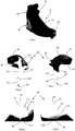
- the figures 2 and 3 more specifically illustrate the rear buttress 10 of the cross-country ski boot 1.
- the buttress is positioned above the casing 6.
- the buttress could be integrated into the thickness of the upper 6.
- the rear buttress 10 is an element of the one-piece cross-country ski boot, intended to wrap the heel, the ankle and the rear of the sole of the user.
- the rear buttress 10 is made of a wall whose thickness can be of the order of a millimeter. The thickness of the wall is not necessarily uniform.
- the rear buttress 10 may include an edge 12 of substantially constant width.
- the edge 12 follows the upper contour of the rear buttress 10 and has a thickness less than the others parts of the rear buttress 10.
- the rear buttress 10 also includes curvatures intended to conform to the natural shape of a foot.
- the rear buttress 10 can be broken down into four faces F1, F2, F3, F4.
- a first face F1 extends vertically and longitudinally along the inner malleolus of the foot and therefore forms an inner lateral part of the rear buttress 10.
- a second face F2 extends vertically and longitudinally along the outer malleolus of the foot and forms therefore an outer lateral part of the rear buttress 10.
- a third face F3 extends substantially horizontally under the foot up to about half the length of the foot.
- a fourth face F4 extends vertically and transversely along the heel of the foot.
- the third face F3 and the fourth face F4 form a middle part of the rear buttress 10, in other words a central part of the rear buttress 10 framed by two lateral parts which form the first face and the second face.
- the middle part makes it possible to connect the two lateral faces of the rear buttress 10 together.
- the four faces are not flat to best match the natural shapes of the foot.
- the fourth face F4 has a rounded shape matching the shape of a heel and is connected without stops to the first and second faces F1, F2.
- the first face F1 and the second face F2 may each have substantially the shape of a quadrilateral.
- a first side C1 forms a horizontal edge with the third face F3.
- a second side C2 extends substantially vertically along an Achilles tendon.
- a third side C3 extends from the top of the second side C2 to the height of a malleolus of one foot.
- a fourth side C4 extends from the malleolus to the front end of the first side C1.
- the first side F1 and the second side F2 comprise a rounding intended to pass above the inner malleolus and above the external malleolus of the foot.
- the third face F3 further comprises a notch 11 extending longitudinally, and intended to be positioned under the sole.
- the third face F3 has substantially the shape of a "U".
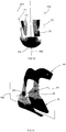
- the rear buttress 10 comprises three distinct zones Z1, Z2, Z3 respectively called first zone Z1, second zone Z2 and third zone Z3. These three areas are delimited by dotted lines on the figures 2, 3 and 4 .
- the first zone and the second zone are white and the third zone is black. Alternatively, these two colors could be any other color.
- the color of the first, second and third zones could be different, or alternatively, identical.
- the first zone Z1 comprises two plastic materials M11, M12 co-injected into the thickness of the wall.
- the first plastic material M11 of the first zone Z1 forms two layers of the wall respectively constituting an internal face Fi and an external face Fe of the wall of the rear buttress 10.
- the internal face Fi designates the face of the rear buttress 10 facing the foot (that is to say towards the inside of the shoe), while the external face Fe designates the face of the rear buttress 10 facing towards the outside of the shoe.
- the second plastic material M12 of the first zone Z1 is interposed between the two layers of the first plastic material M11 of the first zone Z1. The second plastic material M12 used in the first zone Z1 is therefore not apparent.
- the wall of the rear buttress 10 therefore has a sandwich structure comprising three distinct layers.
- the first plastic material M11 of the first zone Z1 is more rigid than the second plastic material M12 of the first zone Z1.
- These two materials M11 and M12 may be of the same nature but have different rigidities, such as for example polyurethane materials of different rigidity.
- the second zone comprises, according to a first option, a structure similar to that of the first zone or, according to a second option, a single material.
- the second zone Z2 comprises two plastic materials M21, M22 co-injected in its thickness.
- the first plastic material M21 of the second zone Z2 forms two layers of the wall respectively constituting an internal face and an external face of the wall of the rear buttress 10.
- the second plastic material M22 of the second zone Z2 is interposed between the two layers of the first plastic material M21 of the second zone Z2.
- the second plastic material M22 of the second zone Z2 is less rigid than the first plastic material M21 of the second zone Z2. Note that the first material M11 of the first zone Z1 can be different from the first material M21 of the second zone Z2, and the second material M12 of the first zone Z1 can be different from the second material M22 of the second zone Z2.
- the second zone comprises only the second material M22 or a third material.
- the second material M22 or the third material has a lower rigidity than the first plastic material M11 of the first zone.
- the third zone Z3 only comprises the second plastic material M12 from the first zone and / or the second plastic material M22 from the second zone Z2.
- the rigidity of the material constituting the third zone is always less than the rigidity of the assembly constituted by the two materials M11, M12 of the first zone.
- the rigidity of a given area designates the rigidity of the materials that make up this area.
- the first zone Z1 extends in the first face F1. More precisely, the first zone Z1 extends in an upper part F11 of the first face F1 surrounding the inner malleolus.
- the second zone Z2 extends in the second face F2.
- the second zone Z2 extends in an upper part F21 of the second face F2 surrounding the external malleolus.
- the third zone Z3 extends between the first zone Z1 and the second zone Z2.
- the third zone extends in particular in the entirety of the third face F3 and of the fourth face F4 as well as in the lower parts F12, F22 respectively of the first and second faces F1, F2.
- the lower part F12 is complementary to the upper part F11.
- the lower part F22 is complementary to the upper part F21.
- the first zone and the second zone are disjoint, that is to say that they do not meet.
- the first zone and the second zone are separated by the third zone.
- the first zone Z1 and / or the second zone Z2 could be more or less large. They could extend respectively in the entirety of the first face F1 and / or of the second face F2, and / or in part in the third face F3, and / or in part in the fourth face F4. In particular, the first zone Z1 and the second zone could meet at least locally in the fourth face F4. A bridge formed by the first materials M11 and M21 would form between the first zone Z1 and the second zone Z2. The zones Z1 and Z2 would then no longer be separated.
- the rear buttress 10 therefore comprises on the one hand at least one inner lateral part formed by co-injection of the two plastic materials M11 and M12, and on the other hand a middle part, or in other words a central part, formed only by the material plastic M12 or M22.
- the inner side part which is also more stressed by mechanical stresses that the middle part when practicing cross-country skiing, therefore includes greater rigidity than the middle part.
- the second zone is produced according to the first option described above, that is to say that it comprises a sandwich structure comprising three distinct layers with the second plastic material M22 of the second zone Z2 interposed between the two layers of the first plastic material M21 of the second zone Z21.
- the first material M11 of the first zone Z1 is identical to the first material M21 of the second zone Z2
- the second material M12 of the first zone Z1 is identical to the second material M22 of the second zone.
- the third zone has a rigidity lower than the rigidity of the first zone and the rigidity of the second zone.
- the middle part of the rear buttress is framed by two more rigid lateral faces F1 and F2, which allows on the one hand an effective transmission of the impulses of the user from his leg and his foot to the ski, and which on the other hand, offers better support for the user's foot in the longitudinal axis when practicing cross-country skiing.
- first material M1 will be used to denote the first plastic material M11 of the first zone Z1 and the first plastic material M21 of the second zone Z2.
- second material M2 will be used to denote the second plastic material M12 of the first zone Z1 and the second plastic material M22 of the second zone Z2.
- the first material M1 is more rigid than the second material M2. That is to say that the first material deforms less than the second material for a given stress.
- the rigidity of a plastic material can also be characterized with its Young's modulus. When the material is a plastic material, the rigidity is a function of its hardness. Thus the more rigid a plastic material, the harder it is, and vice versa.
- the first material M1 has a hardness greater than the hardness of the second material M2.
- the first material M1 is positioned in the upper parts F11, F21 respectively of the first face F1 and the second face F2. These two parts are the parts of the rear buttress requiring the most rigidity to effectively transmit the impulse given by the user to the ski, for the practice of cross-country skiing according to the so-called classic technique. These two parts are also the most mechanically stressed parts of the rear buttress when the shoe is used. These are also the parts of the rear buttress responsible for maintaining or supporting the user's foot when practicing cross-country skiing.
- the second M2 material is more flexible, and is found in the parts of the rear buttress requiring the most flexibility because in contact with sensitive parts of the foot, namely the heel and the soles of the feet.
- the rear buttress By using a more flexible material under the soles of the feet and around the heel, the rear buttress easily envelops these parts of the foot which improves comfort.
- the use of a more flexible material also makes it possible to reduce friction, overheating or the risk of the formation of a blister in these parts of the foot.
- the hardness difference between the two materials is greater than or equal to 3 ShD.
- the first material can be polyurethane with a hardness between 60 and 70 ShD inclusive, or any other plastic material of equivalent hardness, such as for example a polyolefin, while the second material may be polyurethane of hardness between 55 and 65 ShD inclusive, or any other plastic material of equivalent hardness.
- the stiffness difference between the two materials can be greater than or equal to 100 MPa.
- the first material can be polyurethane with a flexural modulus of between 250 and 450 Mpa, or any other plastic material with an equivalent modulus
- the second material can be polyurethane with a flexural modulus between 150 and 350 Mpa.
- the first material can be polyamide with a tensile modulus of between 800 and 1200 MPa, or any other plastic material with an equivalent modulus, while the second material can be polyamide with a tensile modulus between 100 and 300 Mpa.
- the two materials may be identical but of different hardness and / or stiffness, or they may be different.
- the first material can be polyurethane and the second polyamide or a block amide polyether.
- a co-injection of the two plastic materials M1, M2 is carried out in an injection mold comprising two injection nozzles.
- Each injection nozzle is capable of injecting the two plastic materials M1, M2.
- the two injection nozzles inject the plastic materials respectively through a first and a second injection point PI1, PI2.
- the rear buttress 10 is obtained by co-injection through a first injection point PI1 positioned on the internal side with respect to the median plane PM, and through a second injection point PI2 positioned on the external side by relation to the median plane PM.
- the rear buttress 10 could be manufactured using a greater number of injection nozzles.
- a third injection nozzle could be positioned on one side or the other of the median plane or at the level of the median plane itself.
- the rear buttress could also be made with two injection nozzles on each side of the median plane PM, that is to say with four injection nozzles in all.
- a third plastic material or even even more different plastic materials could be co-injected, or even simply injected, or even over-injected for the manufacture of the rear buttress 10.
- Co-injection is based on at least two successive phases of injection, through the same injection point, of the first plastic material M1 then of the second plastic material M2, these two phases being sufficiently close together to induce a nesting of the second plastic material injected through the first plastic material injected.
- the first plastic material M1 is injected into the mold. It remains sufficiently fluid at the time of the injection of the second plastic material M2 through the first material in the same mold, in particular at the level of its internal surface which remains hot longer than its external surfaces, which cool faster in contact with the walls of the injection mold.
- the mentioned nesting manifests itself in two ways. First, the second injected plastic material partially penetrates the layer formed by the first plastic material injected by the first injection.
- the second plastic material penetrates through the internal surface of this mentioned layer under the effect of the significant energy during its injection and comes s extend in the thickness of the first layer, finally forming a wall area called "sandwich" in which the second injected plastic material is enclosed between two layers of the first injected material. Then, the second injected plastic material transports part of the first plastic material from the first injection, beyond its position reached during the first injection, to a border area where the two plastic materials are substantially mixed and alternated, before the second plastic material does not continue to move alone beyond this zone border. This creates a border area or intermediate area between the two materials that does not have a clear or linear limit.
- the first material being irregularly entrained, it can form “flame” type shapes, of direction defined by the direction of injection of the second material, at the border beyond which the first injected material disappears. .
- the second material can punctually reach the external walls of the element alternately with the first material.
- the first material could occasionally penetrate partially into the central part of the second material.
- the positioning of the border zone can fluctuate by about one centimeter.
- the two plastic materials M1, M2 are co-injected by a first nozzle on the inside of the median plane PM.
- the manufacturing process co-injects the two plastic materials M1, M2 by a second nozzle on the outside of the median plane PM.
- these two steps are executed simultaneously but, as a variant, they could be executed quickly one after the other.
- the second nozzle would only inject this second material.
- the first plastic material M1 is diffused in the rear buttress 10 from the injection points through which it is injected.
- the layers formed by the first plastic material M1 and / or the layer formed by the second plastic material M2 can have a substantially uniform thickness within the first zone and the second zoned.
- the first zone can thus be defined as a set of points of the rear buttress whose distance from the first injection point PI1 is less than a given value. This distance is between 2 and 7 cm, preferably between 3.5 and 5.5 cm.
- the second zone Z2 can thus be defined as a set of points of the rear buttress whose distance from the second injection point PI2 is less than a given value. This distance is between 2 and 7 cm, preferably between 3.5 and 5.5 cm.
- the layers formed by the first plastic material M1 and / or the layer formed by the second plastic material M2 could have a different thickness within the first zone and the second zone, in order to increase / decrease the rigidity of these areas.
- the layers of first material M1 could be thinner than the central layer of second material M2, or vice versa.
- the first injection point PI1 is positioned at the top of the upper part F11 of the first face F1. More precisely, this injection point PI1 is positioned at the top of the fourth side C4, on the edge thereof, between a rounded part of the upper contour of the first face connecting the fourth side C4 to the third side C3 and a straight part of the upper contour forming the fourth side.
- the second injection point PI2 can be positioned substantially symmetrically at the first injection point with respect to the median plane PM, at the top of the upper part F21 of the second face F2.
- the injection points PI1, PI2 may be visible on the rear buttress 10 because the second material M2 may be visible on the edge of the wall or in the form of a flame originating at the injection point PI1, PI2 .
- the second zone can extend asymmetrically to the first zone with respect to the median plane PM.
- the quantity (otherwise said, the mass) of first material in the first zone may differ from the amount of first material in the second zone.
- We can thus obtain a different stiffness from the first face F1 compared to the second face F2 of the rear buttress 10.
- the shape of the inside of a foot being different from the shape of the outside of a foot the first side may have a shape different from the shape of the second side. So even if the quantities of first material are identical in the first zone and in the second zone, the first material can be distributed differently in the first zone compared to the second zone.
- the third zone Z3 of the rear buttress 10 comprises the second material M2 originating from the first injection nozzle and originating from the second injection nozzle.
- a weld line LS shown on the figure 4 , is formed where the second material from the first nozzle is welded with the second material from the second nozzle.
- the weld line LS is therefore produced in the third zone Z3. It is therefore outside the first and second zones.
- the weld line LS is therefore formed outside the most mechanically stressed parts of the rear buttress 10, which makes it more robust because the weld lines can constitute lines of weakness of an injected plastic element.
- the second material M2 can be chosen not only as a function of its rigidity but also as a function of its ability to form a solid weld line in an injection process.
- the figure 5 illustrates a second cross-country ski boot 21 according to a second embodiment of the invention.
- This second cross-country ski boot 21 is specially adapted to the practice of cross-country skiing according to the technique known as "skating step", which consists of advancing by alternately giving pulses on each ski, these pulses being oriented from the inside. outwards. Following each pulse, the ski is brought back in a longitudinal orientation while remaining raised so as not to be in contact with snow.
- the second cross-country ski boot 21 is a straight boot and comprises a sole 22 provided with crampons 23 and a means of attachment 24 to a ski.
- the sole 22 may include a rigidity specifically adapted to the practice of cross-country skiing according to the skating step technique.
- the fixing means 24 comprises in particular an axis 25 oriented transversely, and able to cooperate with a fixing device fixed to a cross-country ski.
- the second cross-country ski boot 21 also includes an envelope 26 capable of wrapping the top of a foot.
- the envelope 26 or upper of the shoe may comprise a membrane, made for example from fabric, and an opening and closing device, in particular a zipper 27, to allow easy insertion of the foot into the shoe.
- the envelope 26 can be designed to be elastic and waterproof against water and snow.
- the shoe is rising, that is to say it extends upwards above the ankle of the user.
- the second cross-country ski boot 21 also includes a rear buttress 30 according to an embodiment of the invention and a collar 40 according to an embodiment of the invention.
- the rear buttress 30 and the collar 40 are articulated in rotation relative to each other along an axis of rotation A1 oriented transversely (shown in the figure 11 ).
- the rear buttress comprises a first articulation means formed by a first bearing 31, and a second articulation means formed by a second bearing 32.
- the collar comprises a first articulation means formed by a first bearing 41, and a second articulation means formed by a second bearing 42.
- the axis of rotation A1 is substantially aligned with an axis passing through the two malleoli inside and outside of the foot.
- the axis of rotation A1 is also an axis perpendicular to the median plane PM.
- the first bearing 31 of the rear buttress 30 cooperates with the first bearing 41 of the collar 40 to form a first rotation connection between the rear buttress 30 and the collar 40 on the inside.
- the second bearing 32 of the rear buttress 30 cooperates with the second bearing 42 of the collar 40 to form a second rotational connection between the rear buttress 30 and the collar 40 on the outside.
- the four bearings 31, 32, 41, 42 are formed by circular holes which are particularly visible on the figures 6, 7, 9 and 10 .
- the cross-country ski boot further comprises two axes 28, 29 cooperating respectively with the first two bearings and with the two second bearings.
- a first axis 28 passes through the two holes on the inside and a second axis 29 passes through the two holes on the outside.
- These two axes 28, 29 may for example be rivets or screws.
- the rear buttress 30 is identical to the rear buttress 10 previously described except for a few differences or particularities which we will describe with reference to figures 8, 9 and 10 . To facilitate the description, the same reference signs will be used for the description of the rear buttress 30 as for the description of the rear buttress 10.
- the first face F1 of the rear buttress 30 comprises the first bearing 31 positioned at the height of the internal malleolus. Compared to the shape of the first face F1 of the rear buttress 10, the first face F1 of the rear buttress 30 comprises a first upper protrusion 33 in the form of a half-disc forming a strip of material around the first bearing 31. Similarly, the second face F2 of the rear buttress 30 comprises the second bearing 32 positioned at the height of the external malleolus. Compared to the shape of the second face F2 of the rear buttress 10, the second face F2 of the rear buttress 30 comprises a second upper projection 34 in the form of a half-disc forming a strip of material around the second bearing 32. Thus, a minimum thickness of material separates respectively the first bearing 31 from the edges of the first face F1, and the second bearing 32 from the edges of the second face F2.
- the first zone Z1 and the second zone Z2 of the rear buttress 30 can be respectively more extensive than the first zone Z1 and the second zone Z2 of the rear buttress 10.
- the rear buttress 30 may comprise a proportion more high of the first material M1 compared to the second material M2.
- the first zone extends in an upper part F11 of the first face forming almost all of the first face F1.
- the first zone could extend in a more or less vast part of the first face F1.
- the first bearing 31 and the first protuberance 33 are completely formed in the first zone Z1.
- the second zone extends in an upper part F21 of the second face F2 forming almost all of the second face F2.
- the second zone could extend in a more or less vast part of the second face F2.
- the second bearing 32 is completely formed in the second zone Z2.
- the first zone Z1 and the second zone Z2 also extend partly in the fourth face F4. Flames formed by the first material join flames formed by the second material at the mid plane PM.
- the fourth face F4 includes both the first zone Z1, the second zone Z2 and the third zone Z3.
- the third zone Z3 therefore extends partly in the fourth face F4 but also in the entire third face F3 as well as in two lower parts F12, F22 respectively forming two lower strips of the first face and the second face.
- the fourth face F4 could include only the third zone Z3.
- the first material such as flame 35 visible on the figures 8, 9 and 10
- the first material such as flame 35 visible on the figures 8, 9 and 10
- these flames make it possible to obtain good cohesion between the different plastic materials used.
- the rear buttress 30 comprises lateral parts which are even more rigid than the lateral parts of the rear buttress 10, the rear buttress 30 transmits the impulses from the user to the ski efficiently and without loss of energy, while ensuring good hold. of the foot.
- the manufacture of the rear buttress 30 is obtained by a co-injection method also similar to the method of manufacturing the rear buttress 10 previously described. Thus, we endeavor to describe only the specificities or the differences between the method of manufacturing the rear buttress 30 and the method of manufacturing the rear buttress 10.
- two injection nozzles positioned respectively at the upper end of the first face and of the second face are used.
- the two injection points PI1, PI2 are positioned near the protuberances 33, 34, a short distance from the bearings 31, 32. This ensures that the proportion of the first material relative to the second material is sufficiently high near the two bearings 31, 32.
- the Figures 6 and 7 illustrate the collar 40 according to an embodiment of the invention.
- the collar 40 is an element of the one-piece cross-country ski boot 21, intended to surround the bottom of the user's leg, above his ankle.
- the collar 40 is made of a wall whose thickness can be of the order of a millimeter. The thickness of this wall is not necessarily uniform.
- the collar 40 is formed by a first branch 43, a second branch 44, a rear crosspiece 45 and two tabs 46, 47.
- the first branch 43 extends vertically upwards from the inner malleolus.
- the first branch 43 forms an inner lateral part of the collar.
- the first branch 43 comprises at its lower end the first bearing 41 as well as a first counterbore 48 intended to receive a head of the first axis 28.
- the second branch 44 extends vertically upwards from the external malleolus.
- the second branch 44 forms an external lateral part of the collar.
- the second branch 44 comprises at its lower end the second bearing 42 as well as a second counterbore 49 intended to accommodate a head of the second axis 29 (clearly visible on the figure 11 ).
- the first branch and the second branch extend upward in that they follow the orientation of the leg itself assumed to be oriented vertically. If the user bends the ankle in one direction or another, he requests the articulation in rotation of the cross-country ski boot. In this case the first branch and the second branch are oriented upwards and forwards or upwards and backwards depending on the direction in which the ankle is bent.
- the rear crossmember 45 connects an upper end of the first branch 43 to an upper end of the second branch 44.
- the rear crossmember 45 surrounds the rear of the lower leg substantially at the level of the bottom of the calf. Consequently, the rear crossmember includes a rounded shape capable of enveloping the natural shape of the calf.
- the rear cross member forms a median part of the collar because it is framed transversely by the two branches 43, 44. In other words, the two lateral branches 43, 44 are connected to each other via the rear cross member 45.
- the two tongues 46, 47 extend longitudinally forward respectively in the extension of the first branch 43 and the second branch 44.
- the two tongues can also be bent in the direction of the median plane PM.
- the two tongues each include a hole 50, 51 able to cooperate with a clamping means.
- the clamping means may in particular be a hook strap 52 as shown on the figure 5 .
- the tightening means could also be for example a lace or a hook.
- the collar 40 comprises three distinct zones Z1, Z2, Z3 respectively called first zone Z1, second zone Z2 and third zone Z3.
- the three zones Z1, Z2 and Z3 of the collar 40 correspond to the same definitions as the three zones Z1, Z2, Z3 described for the rear buttresses 10, 30.
- the first branch 43 is included in the first zone Z1. In other words, the first zone extends throughout the entire first branch. The first zone extends even beyond the first branch, in a part of the first tongue 46 and in a part of the rear cross member 45.
- a lower part of the second branch 44, comprising the second bearing 42 and the countersinking 49, is included in the second zone Z2. In other words, the second zone extends only in the lower part of the second branch 44.
- the second zone extends neither in the second tongue 47, nor in the rear cross member 45.
- the second tongue 47 is included in the third zone Z3.
- the third zone Z3 extends in the whole of the second tongue 47.
- the third zone Z3 also extends in an upper part of the second branch 44 and in a part of the rear cross member 45.
- the first zone Z1 remains disjoined from the second zone Z2.
- the first zone can be linked to the second zone, for example via a lower part of the cross-member 45. That is to say that a bridge constituted by the first materials M11 and / or M21 is would form between the first zone Z1 and the second zone Z2. The zones Z1 and Z2 would then no longer be separated.
- the first zone can extend only in a part of the first branch 43, in particular near the bearing 41.
- the second zone can extend only in a part of the second branch 44, in particular near the bearing 42.
- the amount of first material in the first branch is greater than the amount of first material in the second branch. Consequently, the inner branch of the collar is more rigid than the outer branch of the collar. This branch also receives greater constraints because the amplitude of flexion of the ankle is greater inward than outward.
- the second tongue 47 being produced only with the second material, it is also more flexible and can easily adapt to the morphology of a lower leg. In particular, it can easily be bent to wrap the user's tibia.
- the use of at least one tongue made only with the second, more flexible material makes it possible to obtain a pleasant and effective tightening around the bottom of the leg whatever its size.
- the two tabs 46 and 47 can be produced only with the second material, which is more flexible and allows better wrapping of the tibia, thus facilitating the tightening of the shoe.
- the injection nozzles positioned at the height of the two bearings 41, 42 are used.
- the injection points PI1, PI2 are positioned vertically under the two bearings 41, 42, at the lowest points of the collar 40.
- the first material diffuses into the collar by raising the branches in a measure which depends on the quantity of first material injected. Although the quantity of first material is less in the second branch than in the first branch, the two bearings 41, 42 and their respective counterbores 48, 49 form part of the first zone or of the second zone and benefit from the rigidity conferred by the first material.
- the bearings 31, 32, 41, 42 cooperate together to form a rotation articulation.
- the bearings 31, 32, 41, 42 are made with the first more rigid material, the articulation in rotation is also particularly rigid. The lateral impulses given by the user with his leg and foot are efficiently transmitted to the ski. Cross-country skiing can thus be guided with precision and without loss of energy.
- the first plastic material may differ from the second plastic material by other mechanical properties.
- the first plastic material may include self-lubricating and / or abrasion resistance properties to facilitate rotation of the collar around the rear buttress and to reduce wear.
- the first plastic material can comprise fillers of teflon, molybdenum, graphite or even glass or carbon fibers.
- the first plastic material and the second plastic material may also differ from each other by other technical characteristics, such as impact resistance, the ability to thermoform (i.e. the ability to deform when the material is heated so as to match the shape of the foot), the density (that is to say the density), or even by the color.
- impact resistance i.e. the ability to deform when the material is heated so as to match the shape of the foot
- density that is to say the density
- the lateral parts of a cross-country ski boot are more exposed to shocks than the middle part which is protected by the cross-country ski.
- the first material can be used only in areas where it is necessary and thus reduce manufacturing costs if the first material is priced higher than the second material.
- the median plane PM defines two left and right parts of an element which can be the rear buttress 10, 30 or the collar 40.
- the left and right parts have a similar or similar shape.
- the median plane PM can be a plane of symmetry of the outer envelope of the element. That is to say that, by considering only the geometric shape of an element, and not the materials which constitute it, the median plane PM is a plane of symmetry of the element considered.
- the median plane constitutes a plane of symmetry of the element, in particular of the collar, this element can be indifferently used for the manufacture of a left shoe or a right shoe. We can therefore save on injection molds since a single mold can be used instead of at least two molds to make an element for left shoe and an element for right shoe.
- cross-country ski boot elements are often biased asymmetrically, in particular for the practice of cross-country skiing according to the skating step technique.
- An asymmetry of the rigidity of such an element can then be sought.
- this asymmetry can be obtained only by adjusting the size of the first zone and of the second zone, that is to say by adjusting the quantity of first material on either side of the mid plane PM.
- the first plastic material could have a rigidity lower than the second plastic material.
- the plastic material of greater rigidity could form the intermediate layer while the plastic material of lower rigidity would form two internal and external layers respectively in contact with the foot and with the outside of the shoe. The material of greater rigidity would thus be made invisible from the outside in the first zone Z1 and in the second zone Z2.
- the middle part of the cross-country ski boot element which could be made of two different plastic materials, co-injected into the thickness of the middle part, while the inner lateral parts and exterior would consist of only one of these two plastic materials.
- the plastic material constituting the side parts could have greater rigidity than the other plastic material coinjected in the middle part, so that the side parts would have a greater rigidity than the middle part.
- the invention there is a cross-country ski boot adapted to the so-called “traditional” technique or adapted to the technique called “skating step”.
- the boot includes stiffer side parts for an efficient and energy-free transmission of the user's impulses to the ski, and a less rigid middle part allowing to increase the comfort of the user without degrading the performance of the shoe.
- the invention makes it possible to obtain a rigid, robust and durable articulation, which also allows an efficient transmission and without loss of energy of the user's impulses towards the ski.
Landscapes
- Health & Medical Sciences (AREA)
- General Health & Medical Sciences (AREA)
- Physical Education & Sports Medicine (AREA)
- Chemical & Material Sciences (AREA)
- Engineering & Computer Science (AREA)
- Materials Engineering (AREA)
- Footwear And Its Accessory, Manufacturing Method And Apparatuses (AREA)
Priority Applications (1)
| Application Number | Priority Date | Filing Date | Title |
|---|---|---|---|
| EP18425107.2A EP3673761B1 (de) | 2018-12-27 | 2018-12-27 | Element eines langlauf-skischuhs, das durch koinjektion hergestellt wird |
Applications Claiming Priority (1)
| Application Number | Priority Date | Filing Date | Title |
|---|---|---|---|
| EP18425107.2A EP3673761B1 (de) | 2018-12-27 | 2018-12-27 | Element eines langlauf-skischuhs, das durch koinjektion hergestellt wird |
Publications (2)
| Publication Number | Publication Date |
|---|---|
| EP3673761A1 true EP3673761A1 (de) | 2020-07-01 |
| EP3673761B1 EP3673761B1 (de) | 2021-08-11 |
Family
ID=65657190
Family Applications (1)
| Application Number | Title | Priority Date | Filing Date |
|---|---|---|---|
| EP18425107.2A Active EP3673761B1 (de) | 2018-12-27 | 2018-12-27 | Element eines langlauf-skischuhs, das durch koinjektion hergestellt wird |
Country Status (1)
| Country | Link |
|---|---|
| EP (1) | EP3673761B1 (de) |
Cited By (1)
| Publication number | Priority date | Publication date | Assignee | Title |
|---|---|---|---|---|
| FR3125393A1 (fr) * | 2021-07-22 | 2023-01-27 | Lemaitre Securite | Dispositif de protection d’une cheville |
Families Citing this family (1)
| Publication number | Priority date | Publication date | Assignee | Title |
|---|---|---|---|---|
| CN109720830B (zh) * | 2017-10-30 | 2024-02-20 | 杭州海康机器人股份有限公司 | 自动导向搬运车的上件装置及其控制方法、上件控制系统 |
Citations (4)
| Publication number | Priority date | Publication date | Assignee | Title |
|---|---|---|---|---|
| FR2032834A5 (de) * | 1969-02-10 | 1970-11-27 | Austin Luther Sons Ltd | |
| EP0808708A1 (de) * | 1996-05-20 | 1997-11-26 | NORDICA S.p.A. | Verfahren zum Anspritzen auf einen Kunststoff |
| EP1795082A1 (de) * | 2005-12-07 | 2007-06-13 | Lange International S.A. | Sport shoe with decoration |
| EP3103630A1 (de) * | 2015-06-11 | 2016-12-14 | Rossignol Lange S.R.L. | Koinjizierter sportschuh |
-
2018
- 2018-12-27 EP EP18425107.2A patent/EP3673761B1/de active Active
Patent Citations (4)
| Publication number | Priority date | Publication date | Assignee | Title |
|---|---|---|---|---|
| FR2032834A5 (de) * | 1969-02-10 | 1970-11-27 | Austin Luther Sons Ltd | |
| EP0808708A1 (de) * | 1996-05-20 | 1997-11-26 | NORDICA S.p.A. | Verfahren zum Anspritzen auf einen Kunststoff |
| EP1795082A1 (de) * | 2005-12-07 | 2007-06-13 | Lange International S.A. | Sport shoe with decoration |
| EP3103630A1 (de) * | 2015-06-11 | 2016-12-14 | Rossignol Lange S.R.L. | Koinjizierter sportschuh |
Cited By (1)
| Publication number | Priority date | Publication date | Assignee | Title |
|---|---|---|---|---|
| FR3125393A1 (fr) * | 2021-07-22 | 2023-01-27 | Lemaitre Securite | Dispositif de protection d’une cheville |
Also Published As
| Publication number | Publication date |
|---|---|
| EP3673761B1 (de) | 2021-08-11 |
Similar Documents
| Publication | Publication Date | Title |
|---|---|---|
| EP1100349B1 (de) | Schuhsohle | |
| EP0991334B1 (de) | Schuh mit verformbarer besohlung | |
| EP0787441B1 (de) | Sportschuh | |
| EP3103630B1 (de) | Koinjizierter sportschuh | |
| EP0941675B1 (de) | Skischuh | |
| EP1247468A1 (de) | Wanderschuh mit anbringbarer Schuhschaftverstärkung und Verstärkung für einen solchen Schuh | |
| FR2864882A1 (fr) | Chaussure a semelle interchangeable | |
| FR2923362A1 (fr) | Chaussure a serrage de tige ameliore | |
| CA2791159A1 (fr) | Chaussure a serrage de tige ameliore | |
| WO2010136607A1 (fr) | Chaussure de sport de type à crampons | |
| EP3673761B1 (de) | Element eines langlauf-skischuhs, das durch koinjektion hergestellt wird | |
| FR2967874A1 (fr) | Chaussure de sport de type a crampons | |
| EP3195748B1 (de) | Sohle eines langlauf-skischuhs | |
| FR2771902A1 (fr) | Chaussure de ski alpin a tige souple | |
| EP0933100A1 (de) | Bindung für einen Schuh an einem Snowboard | |
| EP1712147B1 (de) | Leicht anzuziehender Sportschuh | |
| EP1813320B1 (de) | Schneegleitbrett, das zwei Zusatzelemente umfasst, die mit einem Verbindungsorgan verbunden sind | |
| FR2896425A1 (fr) | Dispositif d'accueil d'un pied ou d'une chaussure sur un engin de sport | |
| EP1785047B1 (de) | Sportschuh mit schwenkbarer Sohle | |
| EP1765232B1 (de) | Schuhfersenschale, und schuh mit entsprechender fersenschale versehen | |
| WO1997027772A1 (fr) | Chaussure avec raidisseur de torsion | |
| EP3123884B1 (de) | Sohle eines gleitsportschuhs | |
| EP0941676B1 (de) | Schuh für Gleitsporten | |
| FR2914156A1 (fr) | Chaussure de sport. | |
| FR2742637A1 (fr) | Semelle de securite moulee et insert pour une telle semelle |
Legal Events
| Date | Code | Title | Description |
|---|---|---|---|
| PUAI | Public reference made under article 153(3) epc to a published international application that has entered the european phase |
Free format text: ORIGINAL CODE: 0009012 |
|
| STAA | Information on the status of an ep patent application or granted ep patent |
Free format text: STATUS: THE APPLICATION HAS BEEN PUBLISHED |
|
| AK | Designated contracting states |
Kind code of ref document: A1 Designated state(s): AL AT BE BG CH CY CZ DE DK EE ES FI FR GB GR HR HU IE IS IT LI LT LU LV MC MK MT NL NO PL PT RO RS SE SI SK SM TR |
|
| AX | Request for extension of the european patent |
Extension state: BA ME |
|
| STAA | Information on the status of an ep patent application or granted ep patent |
Free format text: STATUS: REQUEST FOR EXAMINATION WAS MADE |
|
| 17P | Request for examination filed |
Effective date: 20201221 |
|
| RBV | Designated contracting states (corrected) |
Designated state(s): AL AT BE BG CH CY CZ DE DK EE ES FI FR GB GR HR HU IE IS IT LI LT LU LV MC MK MT NL NO PL PT RO RS SE SI SK SM TR |
|
| GRAP | Despatch of communication of intention to grant a patent |
Free format text: ORIGINAL CODE: EPIDOSNIGR1 |
|
| STAA | Information on the status of an ep patent application or granted ep patent |
Free format text: STATUS: GRANT OF PATENT IS INTENDED |
|
| INTG | Intention to grant announced |
Effective date: 20210312 |
|
| GRAS | Grant fee paid |
Free format text: ORIGINAL CODE: EPIDOSNIGR3 |
|
| GRAA | (expected) grant |
Free format text: ORIGINAL CODE: 0009210 |
|
| STAA | Information on the status of an ep patent application or granted ep patent |
Free format text: STATUS: THE PATENT HAS BEEN GRANTED |
|
| AK | Designated contracting states |
Kind code of ref document: B1 Designated state(s): AL AT BE BG CH CY CZ DE DK EE ES FI FR GB GR HR HU IE IS IT LI LT LU LV MC MK MT NL NO PL PT RO RS SE SI SK SM TR |
|
| REG | Reference to a national code |
Ref country code: CH Ref legal event code: EP |
|
| REG | Reference to a national code |
Ref country code: DE Ref legal event code: R096 Ref document number: 602018021590 Country of ref document: DE |
|
| REG | Reference to a national code |
Ref country code: IE Ref legal event code: FG4D Free format text: LANGUAGE OF EP DOCUMENT: FRENCH Ref country code: AT Ref legal event code: REF Ref document number: 1418468 Country of ref document: AT Kind code of ref document: T Effective date: 20210915 |
|
| REG | Reference to a national code |
Ref country code: LT Ref legal event code: MG9D |
|
| REG | Reference to a national code |
Ref country code: NL Ref legal event code: MP Effective date: 20210811 |
|
| REG | Reference to a national code |
Ref country code: AT Ref legal event code: MK05 Ref document number: 1418468 Country of ref document: AT Kind code of ref document: T Effective date: 20210811 |
|
| PG25 | Lapsed in a contracting state [announced via postgrant information from national office to epo] |
Ref country code: SE Free format text: LAPSE BECAUSE OF FAILURE TO SUBMIT A TRANSLATION OF THE DESCRIPTION OR TO PAY THE FEE WITHIN THE PRESCRIBED TIME-LIMIT Effective date: 20210811 Ref country code: RS Free format text: LAPSE BECAUSE OF FAILURE TO SUBMIT A TRANSLATION OF THE DESCRIPTION OR TO PAY THE FEE WITHIN THE PRESCRIBED TIME-LIMIT Effective date: 20210811 Ref country code: ES Free format text: LAPSE BECAUSE OF FAILURE TO SUBMIT A TRANSLATION OF THE DESCRIPTION OR TO PAY THE FEE WITHIN THE PRESCRIBED TIME-LIMIT Effective date: 20210811 Ref country code: FI Free format text: LAPSE BECAUSE OF FAILURE TO SUBMIT A TRANSLATION OF THE DESCRIPTION OR TO PAY THE FEE WITHIN THE PRESCRIBED TIME-LIMIT Effective date: 20210811 Ref country code: HR Free format text: LAPSE BECAUSE OF FAILURE TO SUBMIT A TRANSLATION OF THE DESCRIPTION OR TO PAY THE FEE WITHIN THE PRESCRIBED TIME-LIMIT Effective date: 20210811 Ref country code: BG Free format text: LAPSE BECAUSE OF FAILURE TO SUBMIT A TRANSLATION OF THE DESCRIPTION OR TO PAY THE FEE WITHIN THE PRESCRIBED TIME-LIMIT Effective date: 20211111 Ref country code: AT Free format text: LAPSE BECAUSE OF FAILURE TO SUBMIT A TRANSLATION OF THE DESCRIPTION OR TO PAY THE FEE WITHIN THE PRESCRIBED TIME-LIMIT Effective date: 20210811 Ref country code: LT Free format text: LAPSE BECAUSE OF FAILURE TO SUBMIT A TRANSLATION OF THE DESCRIPTION OR TO PAY THE FEE WITHIN THE PRESCRIBED TIME-LIMIT Effective date: 20210811 Ref country code: NO Free format text: LAPSE BECAUSE OF FAILURE TO SUBMIT A TRANSLATION OF THE DESCRIPTION OR TO PAY THE FEE WITHIN THE PRESCRIBED TIME-LIMIT Effective date: 20211111 Ref country code: PT Free format text: LAPSE BECAUSE OF FAILURE TO SUBMIT A TRANSLATION OF THE DESCRIPTION OR TO PAY THE FEE WITHIN THE PRESCRIBED TIME-LIMIT Effective date: 20211213 |
|
| PG25 | Lapsed in a contracting state [announced via postgrant information from national office to epo] |
Ref country code: PL Free format text: LAPSE BECAUSE OF FAILURE TO SUBMIT A TRANSLATION OF THE DESCRIPTION OR TO PAY THE FEE WITHIN THE PRESCRIBED TIME-LIMIT Effective date: 20210811 Ref country code: LV Free format text: LAPSE BECAUSE OF FAILURE TO SUBMIT A TRANSLATION OF THE DESCRIPTION OR TO PAY THE FEE WITHIN THE PRESCRIBED TIME-LIMIT Effective date: 20210811 Ref country code: GR Free format text: LAPSE BECAUSE OF FAILURE TO SUBMIT A TRANSLATION OF THE DESCRIPTION OR TO PAY THE FEE WITHIN THE PRESCRIBED TIME-LIMIT Effective date: 20211112 |
|
| PG25 | Lapsed in a contracting state [announced via postgrant information from national office to epo] |
Ref country code: NL Free format text: LAPSE BECAUSE OF FAILURE TO SUBMIT A TRANSLATION OF THE DESCRIPTION OR TO PAY THE FEE WITHIN THE PRESCRIBED TIME-LIMIT Effective date: 20210811 |
|
| PG25 | Lapsed in a contracting state [announced via postgrant information from national office to epo] |
Ref country code: DK Free format text: LAPSE BECAUSE OF FAILURE TO SUBMIT A TRANSLATION OF THE DESCRIPTION OR TO PAY THE FEE WITHIN THE PRESCRIBED TIME-LIMIT Effective date: 20210811 |
|
| REG | Reference to a national code |
Ref country code: DE Ref legal event code: R097 Ref document number: 602018021590 Country of ref document: DE |
|
| PG25 | Lapsed in a contracting state [announced via postgrant information from national office to epo] |
Ref country code: SM Free format text: LAPSE BECAUSE OF FAILURE TO SUBMIT A TRANSLATION OF THE DESCRIPTION OR TO PAY THE FEE WITHIN THE PRESCRIBED TIME-LIMIT Effective date: 20210811 Ref country code: SK Free format text: LAPSE BECAUSE OF FAILURE TO SUBMIT A TRANSLATION OF THE DESCRIPTION OR TO PAY THE FEE WITHIN THE PRESCRIBED TIME-LIMIT Effective date: 20210811 Ref country code: RO Free format text: LAPSE BECAUSE OF FAILURE TO SUBMIT A TRANSLATION OF THE DESCRIPTION OR TO PAY THE FEE WITHIN THE PRESCRIBED TIME-LIMIT Effective date: 20210811 Ref country code: EE Free format text: LAPSE BECAUSE OF FAILURE TO SUBMIT A TRANSLATION OF THE DESCRIPTION OR TO PAY THE FEE WITHIN THE PRESCRIBED TIME-LIMIT Effective date: 20210811 Ref country code: CZ Free format text: LAPSE BECAUSE OF FAILURE TO SUBMIT A TRANSLATION OF THE DESCRIPTION OR TO PAY THE FEE WITHIN THE PRESCRIBED TIME-LIMIT Effective date: 20210811 Ref country code: AL Free format text: LAPSE BECAUSE OF FAILURE TO SUBMIT A TRANSLATION OF THE DESCRIPTION OR TO PAY THE FEE WITHIN THE PRESCRIBED TIME-LIMIT Effective date: 20210811 |
|
| PLBE | No opposition filed within time limit |
Free format text: ORIGINAL CODE: 0009261 |
|
| STAA | Information on the status of an ep patent application or granted ep patent |
Free format text: STATUS: NO OPPOSITION FILED WITHIN TIME LIMIT |
|
| 26N | No opposition filed |
Effective date: 20220512 |
|
| PG25 | Lapsed in a contracting state [announced via postgrant information from national office to epo] |
Ref country code: MC Free format text: LAPSE BECAUSE OF FAILURE TO SUBMIT A TRANSLATION OF THE DESCRIPTION OR TO PAY THE FEE WITHIN THE PRESCRIBED TIME-LIMIT Effective date: 20210811 |
|
| REG | Reference to a national code |
Ref country code: CH Ref legal event code: PL |
|
| PG25 | Lapsed in a contracting state [announced via postgrant information from national office to epo] |
Ref country code: SI Free format text: LAPSE BECAUSE OF FAILURE TO SUBMIT A TRANSLATION OF THE DESCRIPTION OR TO PAY THE FEE WITHIN THE PRESCRIBED TIME-LIMIT Effective date: 20210811 |
|
| REG | Reference to a national code |
Ref country code: BE Ref legal event code: MM Effective date: 20211231 |
|
| PG25 | Lapsed in a contracting state [announced via postgrant information from national office to epo] |
Ref country code: LU Free format text: LAPSE BECAUSE OF NON-PAYMENT OF DUE FEES Effective date: 20211227 Ref country code: IE Free format text: LAPSE BECAUSE OF NON-PAYMENT OF DUE FEES Effective date: 20211227 |
|
| PG25 | Lapsed in a contracting state [announced via postgrant information from national office to epo] |
Ref country code: BE Free format text: LAPSE BECAUSE OF NON-PAYMENT OF DUE FEES Effective date: 20211231 |
|
| PG25 | Lapsed in a contracting state [announced via postgrant information from national office to epo] |
Ref country code: LI Free format text: LAPSE BECAUSE OF NON-PAYMENT OF DUE FEES Effective date: 20211231 Ref country code: CH Free format text: LAPSE BECAUSE OF NON-PAYMENT OF DUE FEES Effective date: 20211231 |
|
| PG25 | Lapsed in a contracting state [announced via postgrant information from national office to epo] |
Ref country code: CY Free format text: LAPSE BECAUSE OF FAILURE TO SUBMIT A TRANSLATION OF THE DESCRIPTION OR TO PAY THE FEE WITHIN THE PRESCRIBED TIME-LIMIT Effective date: 20210811 |
|
| P01 | Opt-out of the competence of the unified patent court (upc) registered |
Effective date: 20230530 |
|
| PG25 | Lapsed in a contracting state [announced via postgrant information from national office to epo] |
Ref country code: HU Free format text: LAPSE BECAUSE OF FAILURE TO SUBMIT A TRANSLATION OF THE DESCRIPTION OR TO PAY THE FEE WITHIN THE PRESCRIBED TIME-LIMIT; INVALID AB INITIO Effective date: 20181227 |
|
| GBPC | Gb: european patent ceased through non-payment of renewal fee |
Effective date: 20221227 |
|
| PG25 | Lapsed in a contracting state [announced via postgrant information from national office to epo] |
Ref country code: GB Free format text: LAPSE BECAUSE OF NON-PAYMENT OF DUE FEES Effective date: 20221227 |
|
| PG25 | Lapsed in a contracting state [announced via postgrant information from national office to epo] |
Ref country code: MK Free format text: LAPSE BECAUSE OF FAILURE TO SUBMIT A TRANSLATION OF THE DESCRIPTION OR TO PAY THE FEE WITHIN THE PRESCRIBED TIME-LIMIT Effective date: 20210811 |
|
| PG25 | Lapsed in a contracting state [announced via postgrant information from national office to epo] |
Ref country code: TR Free format text: LAPSE BECAUSE OF FAILURE TO SUBMIT A TRANSLATION OF THE DESCRIPTION OR TO PAY THE FEE WITHIN THE PRESCRIBED TIME-LIMIT Effective date: 20210811 |
|
| PG25 | Lapsed in a contracting state [announced via postgrant information from national office to epo] |
Ref country code: MT Free format text: LAPSE BECAUSE OF FAILURE TO SUBMIT A TRANSLATION OF THE DESCRIPTION OR TO PAY THE FEE WITHIN THE PRESCRIBED TIME-LIMIT Effective date: 20210811 |
|
| PGFP | Annual fee paid to national office [announced via postgrant information from national office to epo] |
Ref country code: DE Payment date: 20241211 Year of fee payment: 7 |
|
| PGFP | Annual fee paid to national office [announced via postgrant information from national office to epo] |
Ref country code: IT Payment date: 20251210 Year of fee payment: 8 |
|
| PGFP | Annual fee paid to national office [announced via postgrant information from national office to epo] |
Ref country code: FR Payment date: 20251230 Year of fee payment: 8 |