EP3674030A1 - Heftschweissverfahren und heftschweissvorrichtung - Google Patents
Heftschweissverfahren und heftschweissvorrichtung Download PDFInfo
- Publication number
- EP3674030A1 EP3674030A1 EP18848349.9A EP18848349A EP3674030A1 EP 3674030 A1 EP3674030 A1 EP 3674030A1 EP 18848349 A EP18848349 A EP 18848349A EP 3674030 A1 EP3674030 A1 EP 3674030A1
- Authority
- EP
- European Patent Office
- Prior art keywords
- joint
- tack
- welding
- joint portion
- filler metal
- Prior art date
- Legal status (The legal status is an assumption and is not a legal conclusion. Google has not performed a legal analysis and makes no representation as to the accuracy of the status listed.)
- Pending
Links
- 238000003466 welding Methods 0.000 title claims abstract description 155
- 238000000034 method Methods 0.000 title claims abstract description 36
- 239000002184 metal Substances 0.000 claims abstract description 60
- 239000000945 filler Substances 0.000 claims abstract description 53
- 229910000831 Steel Inorganic materials 0.000 claims description 19
- 239000010959 steel Substances 0.000 claims description 19
- 239000000463 material Substances 0.000 claims description 13
- 230000001678 irradiating effect Effects 0.000 claims description 3
- 238000005520 cutting process Methods 0.000 claims description 2
- 239000011324 bead Substances 0.000 abstract description 20
- 230000002787 reinforcement Effects 0.000 abstract description 11
- 238000012986 modification Methods 0.000 description 16
- 230000004048 modification Effects 0.000 description 16
- 238000012360 testing method Methods 0.000 description 12
- 238000003825 pressing Methods 0.000 description 6
- 230000000052 comparative effect Effects 0.000 description 5
- 230000035515 penetration Effects 0.000 description 5
- 230000010355 oscillation Effects 0.000 description 4
- 238000013459 approach Methods 0.000 description 3
- 239000013307 optical fiber Substances 0.000 description 2
- 238000007796 conventional method Methods 0.000 description 1
- 238000006073 displacement reaction Methods 0.000 description 1
- 230000000694 effects Effects 0.000 description 1
- 238000007689 inspection Methods 0.000 description 1
- 238000003754 machining Methods 0.000 description 1
- 238000012545 processing Methods 0.000 description 1
- 230000032258 transport Effects 0.000 description 1
- 238000011144 upstream manufacturing Methods 0.000 description 1
Images


Classifications
-
- B—PERFORMING OPERATIONS; TRANSPORTING
- B23—MACHINE TOOLS; METAL-WORKING NOT OTHERWISE PROVIDED FOR
- B23K—SOLDERING OR UNSOLDERING; WELDING; CLADDING OR PLATING BY SOLDERING OR WELDING; CUTTING BY APPLYING HEAT LOCALLY, e.g. FLAME CUTTING; WORKING BY LASER BEAM
- B23K26/00—Working by laser beam, e.g. welding, cutting or boring
- B23K26/20—Bonding
- B23K26/21—Bonding by welding
- B23K26/211—Bonding by welding with interposition of special material to facilitate connection of the parts
-
- B—PERFORMING OPERATIONS; TRANSPORTING
- B23—MACHINE TOOLS; METAL-WORKING NOT OTHERWISE PROVIDED FOR
- B23K—SOLDERING OR UNSOLDERING; WELDING; CLADDING OR PLATING BY SOLDERING OR WELDING; CUTTING BY APPLYING HEAT LOCALLY, e.g. FLAME CUTTING; WORKING BY LASER BEAM
- B23K26/00—Working by laser beam, e.g. welding, cutting or boring
- B23K26/08—Devices involving relative movement between laser beam and workpiece
- B23K26/082—Scanning systems, i.e. devices involving movement of the laser beam relative to the laser head
-
- B—PERFORMING OPERATIONS; TRANSPORTING
- B23—MACHINE TOOLS; METAL-WORKING NOT OTHERWISE PROVIDED FOR
- B23K—SOLDERING OR UNSOLDERING; WELDING; CLADDING OR PLATING BY SOLDERING OR WELDING; CUTTING BY APPLYING HEAT LOCALLY, e.g. FLAME CUTTING; WORKING BY LASER BEAM
- B23K26/00—Working by laser beam, e.g. welding, cutting or boring
- B23K26/20—Bonding
- B23K26/21—Bonding by welding
- B23K26/22—Spot welding
-
- B—PERFORMING OPERATIONS; TRANSPORTING
- B23—MACHINE TOOLS; METAL-WORKING NOT OTHERWISE PROVIDED FOR
- B23K—SOLDERING OR UNSOLDERING; WELDING; CLADDING OR PLATING BY SOLDERING OR WELDING; CUTTING BY APPLYING HEAT LOCALLY, e.g. FLAME CUTTING; WORKING BY LASER BEAM
- B23K2101/00—Articles made by soldering, welding or cutting
- B23K2101/04—Tubular or hollow articles
Definitions
- the present invention relates to a tack welding method and a tack welding apparatus, and in particular, to a tack welding method and a tack welding apparatus that enable main welding to be performed efficiently after tack welding.
- a boom that is a component of a crane vehicle, an aerial work vehicle, a bridge inspection vehicle or the like is a long steel structure having a hollow tubular shape.
- a boom is formed into a long tubular shape by butt-welding both open end portions of steel materials having a substantially U-shaped cross section.
- Patent Literature 1 discloses tack welding using MIG welding, tack welding using laser welding, and tack welding using hybrid welding that combines laser welding and arc welding.
- the present invention has been achieved in view of the above problems, and an object of the invention is to provide a tack welding method and a tack welding apparatus that can improve the strength of a tack-welded joint portion and reduce the height of a reinforcement bead.
- a tack welding method of tack-welding a part of a joint portion of a first joint and a second joint at a predetermined interval before main welding includes supplying a filler metal to the joint portion, irradiating laser light to the joint portion while deflecting the laser light, and cutting the filler metal with the laser light to be welded to the joint portion.
- the filler metal may be supplied to the joint portion while being pressed in a state where the filler metal is inclined by a predetermined angle.
- the laser light may be horizontally irradiated with the first joint and the second joint disposed vertically.
- the first joint may be constituted by both end portions of a cross section of a steel material having a substantially U-shaped or substantially semicircular cross section
- the second joint may be constituted by a steel material having a cross section including both end portions facing the both end portions of the first joint.
- two joint portions on left and right sides of the steel material may be simultaneously tack-welded.
- a tack welding apparatus that tack-welds a part of a joint portion of a first joint and a second joint at a predetermined interval before main welding.
- the tack welding apparatus includes a filler metal supply device that supplies a filler metal to the joint portion and a laser welding device that irradiates laser light to the joint portion while deflecting the laser light.
- the filler metal is supplied to a laser welded portion using not arc welding but only laser welding. Consequently, a weld metal can be added to the joint portion to be tack-welded and the strength of the tack-welded joint portion can be improved. Further, as the laser light is irradiated while being deflected in the present invention, the weld metal can be dispersed while the filler metal is cut, and the height of a reinforcement bead can thus be reduced.
- Fig. 1 is an explanatory view illustrating a tack welding method according to an embodiment of the present invention, where (A) is a cross-sectional view of a joint portion and (B) is a front view of the joint portion.
- Fig. 2 is a view illustrating an example of a method of supplying a filler metal illustrated in Fig. 1 , where (A) is a plan view and (B) is a side view.
- a tack welding method of the present embodiment is a tack welding method of tack-welding a part of a joint portion 3 of a first joint 1 and a second joint 2 at a predetermined interval before main welding.
- a filler metal W is supplied to the joint portion 3
- laser light L is deflected and irradiated to the joint portion 3
- the filler metal W is cut with the laser light L to be welded to the joint portion 3.
- an X axis is set in a direction that the joint portion 3 extends
- a Y axis is set in a horizontal direction perpendicular to the X axis
- a Z axis is set in a vertical direction.
- the first joint 1 and the second joint 2 are, for example, steel plates having a predetermined shape. As illustrated in Fig. 1(A) , the first joint 1 and the second joint 2 are tack-welded with the second joint 2 disposed downward and the first joint 1 disposed upward. While a case where a plate thickness of the first joint 1 is larger than a plate thickness of the second joint 2 is illustrated, the plate thickness of the first joint 1 may be equal to the plate thickness of the second joint 2, or the plate thickness of the second joint 2 may be larger than the plate thickness of the first joint 1.
- first joint 1 and the second joint 2 are formed of a steel plate, not a few machining errors and deformations are included in these joints.
- a gap ⁇ g is formed in the joint portion 3 in the Z axis direction.
- tack welding can be performed by supplying the filler metal W.
- the gap ⁇ g is preferably equal to or less than a predetermined threshold (for example, about 1 mm to 2 mm) at a time of tack welding.
- the filler metal W is, for example, a welding wire. As illustrated in Fig. 1(A) , the filler metal W is supplied to the joint portion 3 by a filler metal supply device 4.
- the filler metal supply device 4 includes, for example, a guide member 41 that maintains an orientation of the filler metal W, a welding wire drum 42 in which the filler metal W (welding wire) is wound in a coil shape, and a welding wire feeding device 43 that feeds the filler metal W from the welding wire drum 42 to the guide member 41.
- the filler metal supply device 4 may include a fixing unit that fixes the guide member 41 at a predetermined position.
- the laser light L is irradiated to the joint portion 3 by a laser welding device 5 as illustrated in Fig. 1(A) .
- the laser welding device 5 includes, for example, a laser scan head 51 that deflectably irradiates the laser light L, a laser oscillator 52 that generates laser light, and an optical fiber 53 that transports laser light from the laser oscillator 52 to the laser scan head 51.
- the laser welding device 5 may include a fixing unit that fixes the laser scan head 51 at a predetermined position.
- the filler metal W is supplied in a state of being inclined to the Y axis direction by a predetermined angle ⁇ with respect to the joint portion 3 extending in the X axis direction.
- this angle ⁇ is referred to as "approach angle" of the filler metal W.
- the filler metal W supplied to the joint portion 3 is cut with the laser light L and welded. Consequently, when the approach angle ⁇ is increased, a distance between the cut filler metal W and the joint portion 3 is increased, and thus the degree of welding of the filler metal W may be degraded.
- the filler metal W is thus preferably supplied in a state of being as close to the joint portion 3 as possible.
- the approach angle ⁇ is set in a range of 0° ⁇ ⁇ ⁇ 10°, for example.
- the filler metal W is supplied in a state of being inclined from a side of the second joint 2 to the Z axis direction by a predetermined angle ⁇ with respect to the joint portion 3.
- this angle ⁇ is referred to as "inclination angle" of the filler metal W.
- This inclination angle ⁇ is changed depending on conditions such as the plate thickness of the first joint 1 and the second joint 2. For example, as illustrated in Fig. 1(A) , when the plate thickness of the first joint 1 disposed on the upper side is larger than the plate thickness of the second joint 2 disposed on the lower side, the filler metal W is supplied to the joint portion 3 from the lower side.
- the inclination angle ⁇ may be set to 0°.
- the filler metal W may be supplied to the joint portion 3 from the upper side.
- the laser light L is irradiated in a state of being inclined from the side of the second joint 2 to the Z axis direction by a predetermined angle ⁇ with respect to the joint portion 3.
- this angle ⁇ is referred to as "irradiation angle" of the laser light L.
- the irradiation angle ⁇ is changed according to the plate thickness of the first joint 1 and the second joint 2. For example, as illustrated in Fig. 1(A) , when the plate thickness of the first joint 1 disposed on the upper side is larger than the plate thickness of the second joint 2 disposed on the lower side, the filler metal W is supplied to the joint portion 3 from the lower side.
- the irradiation angle ⁇ may be set to 0°.
- the filler metal W may be supplied to the joint portion 3 from the upper side.
- the laser light L output from the laser scan head 51 is deflected in the Z direction and irradiated to the joint portion 3.
- the laser light L is deflected using, for example, a plurality of deflection mirrors (not illustrated) provided in the laser scan head 51.
- a galvano mirror that vibrates at a high speed, a rotating polygon mirror, or the like can be used as the deflection mirror.
- the laser light L is swung in a zigzag manner at a predetermined cycle in the Z axis direction, as illustrated in Fig. 1(B) .
- a trajectory of the laser light L is referred to as "oscillation”.
- a deflection width S of the laser light L is set to be larger than the gap ⁇ g of the joint portion 3.
- the joint portion 3 is tack-welded for a predetermined length at a predetermined interval.
- the filler metal W supplied to the joint portion 3 can be cut to be welded. Further, by deflecting the laser light L, the cut filler metal W (weld metal) can be dispersed in the joint portion 3, and the height of the reinforcement bead B can thus be reduced.
- the filler metal W is supplied to a laser welded portion using not arc welding but only laser welding. Consequently, a weld metal can be added to the joint portion 3 to be tack-welded and the strength of the tack-welded joint portion 3 can be improved.
- arc welding since arc welding is not used, a current does not need to flow through the first joint 1 and the second joint 2 during tack welding. As a result, a wasteful heat input to a steel material can be reduced and deformations of the steel material can be prevented.
- the weld metal drops downward by its own weight and the height of the reinforcement bead B on a back side may be increased.
- the height of the reinforcement bead B on the back side can be reduced.
- Fig. 3 is a view illustrating a modification of oscillation of laser light, where (A) illustrates a first modification, (B) illustrates a second modification, (C) illustrates a third modification, and (D) illustrates a fourth modification.
- the first modification illustrated in Fig. 3(A) is a case where the laser light L is deflected in a substantially sine wave shape.
- the second modification illustrated in Fig. 3(B) is a case where the laser light L is deflected in a substantially elliptical shape.
- the deflection width on a downstream side in the welding direction may be larger than the deflection width on an upstream side.
- a weld metal can be effectively dispersed.
- the first joint 1 and the second joint 2 are tack-welded by the tack welding method according to the present embodiment described above, and then main welding is performed along the joint portion 3.
- main welding laser arc hybrid welding using both arc welding and laser welding is used, for example.
- profile control is commonly executed on a welding apparatus along the joint portion 3.
- the height of the reinforcement bead B having been tack-welded by the tack welding method according to the present embodiment is reduced on the front side and the back side, and thus the bead B hardly affects the profile control. Consequently, the bead B can be skipped or directly main-welded while the profile control is executed on the welding apparatus.
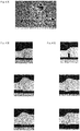
- Fig. 4 is a view illustrating a cross-sectional macro of a test piece, where (A) illustrates a comparative example, (B) illustrates a first test piece, and (C) illustrates a second test piece.
- the division of the scale is 1 mm in each figure.
- the tack welding apparatus includes the filler metal supply device 4 and the laser welding device 5 described above.
- the tack welding apparatus also includes a mounting table 7 that supports the workpiece 6, a pair of guide rails 8 that extend along left and right sides of the mounting table 7, and a movement unit 9 that has a gate shape and moves along the guide rails 8.
- the workpiece 6 is set on the mounting table 7 with the first joint 1 of the upper workpiece 61 and the second joint 2 of the lower workpiece 62 abutting each other.
- the movement unit 9 is then moved to a predetermined position, the workpiece 6 is positioned by the pressing devices 10 and 11, and tack welding is performed simultaneously on the left and right sides by the tack welding method described above. After tack welding, the pressing devices 10 and 11 are released, the movement unit 9 is moved again to the predetermined position, the workpiece 6 is positioned, and tack welding is performed on the workpiece 6. This process is repeated.
- the joint portions 3 on the left and right sides of the workpiece 6 can be tack-welded simultaneously, and thus a processing time of a tack welding process can be reduced.
- the shape of the workpiece 6 is not limited to the illustrated shape, and, for example, a hollow steel material having a substantially quadrangular prism shape used for a column of a steel structure or the like, or a hollow cylindrical steel material used for a pipe or the like may be used.
Landscapes
- Physics & Mathematics (AREA)
- Optics & Photonics (AREA)
- Engineering & Computer Science (AREA)
- Plasma & Fusion (AREA)
- Mechanical Engineering (AREA)
- Laser Beam Processing (AREA)
Applications Claiming Priority (2)
| Application Number | Priority Date | Filing Date | Title |
|---|---|---|---|
| JP2017160780A JP6689238B2 (ja) | 2017-08-24 | 2017-08-24 | 仮付け溶接方法及び仮付け溶接装置 |
| PCT/JP2018/031086 WO2019039528A1 (ja) | 2017-08-24 | 2018-08-23 | 仮付け溶接方法及び仮付け溶接装置 |
Publications (2)
| Publication Number | Publication Date |
|---|---|
| EP3674030A1 true EP3674030A1 (de) | 2020-07-01 |
| EP3674030A4 EP3674030A4 (de) | 2021-05-19 |
Family
ID=65438992
Family Applications (1)
| Application Number | Title | Priority Date | Filing Date |
|---|---|---|---|
| EP18848349.9A Pending EP3674030A4 (de) | 2017-08-24 | 2018-08-23 | Heftschweissverfahren und heftschweissvorrichtung |
Country Status (5)
| Country | Link |
|---|---|
| US (1) | US11801573B2 (de) |
| EP (1) | EP3674030A4 (de) |
| JP (1) | JP6689238B2 (de) |
| CN (1) | CN111032272A (de) |
| WO (1) | WO2019039528A1 (de) |
Families Citing this family (6)
| Publication number | Priority date | Publication date | Assignee | Title |
|---|---|---|---|---|
| JP7289509B2 (ja) * | 2019-04-26 | 2023-06-12 | デルタ工業株式会社 | レーザ溶接方法およびレーザ溶接装置 |
| EP4005724B1 (de) * | 2019-07-24 | 2025-04-09 | IHI Infrastructure Systems Co., Ltd. | Reparatur-laserschweissverfahren und verwendung eines laserschweissgeräts zur reparatur |
| CN115812015B (zh) * | 2020-10-05 | 2025-10-28 | 松下知识产权经营株式会社 | 激光焊接方法以及激光焊接装置 |
| US20220410777A1 (en) * | 2021-06-25 | 2022-12-29 | Fisher & Company, Incorporated | Method Of Welding Vehicle Recliner Mechanisms |
| CN114043108B (zh) * | 2021-12-09 | 2022-11-22 | 西安航天动力机械有限公司 | 一种超高强钢筒形件的等离子+tig焊接方法 |
| WO2023153018A1 (ja) * | 2022-02-14 | 2023-08-17 | Jfeスチール株式会社 | レーザビーム溶接方法とその溶接機ならびに突合せ溶接継手 |
Family Cites Families (25)
| Publication number | Priority date | Publication date | Assignee | Title |
|---|---|---|---|---|
| JPS61119392A (ja) * | 1984-11-14 | 1986-06-06 | Mitsubishi Electric Corp | レ−ザ溶接方法及びレ−ザ溶接装置 |
| JPH10216972A (ja) * | 1997-02-04 | 1998-08-18 | Kubota Corp | レ−ザと消耗電極式ア−クの複合溶接方法 |
| US6770840B2 (en) | 1997-03-28 | 2004-08-03 | Nippon Steel Corporation | Method of butt-welding hot-rolled steel materials by laser beam and apparatus therefor |
| JPH10272584A (ja) * | 1997-03-31 | 1998-10-13 | Nippon Steel Corp | 熱間圧延鋼片の突合せ溶接方法 |
| EP2263822A3 (de) * | 1997-03-28 | 2014-10-01 | Nippon Steel & Sumitomo Metal Corporation | Verfahren und Vorrichtung zum Stumpfschweißen von warmgewalzten Blöcken mit einem Laserstrahl |
| JP2001198689A (ja) * | 2000-01-11 | 2001-07-24 | Kobe Steel Ltd | アルミニウム材のレーザ溶接方法 |
| KR100419368B1 (ko) * | 2000-01-12 | 2004-03-04 | 가부시키가이샤 아크리에이토 | 철골구조물의 일측용접방법 |
| JP4604419B2 (ja) * | 2000-09-29 | 2011-01-05 | 株式会社デンソー | ガスセンサの製造方法及び製造装置 |
| JP2002172477A (ja) | 2000-12-04 | 2002-06-18 | Nkk Corp | レーザ・アーク複合仮付溶接方法 |
| JP2002283078A (ja) * | 2001-01-22 | 2002-10-02 | Komatsu Ltd | レーザ溶接方法 |
| JP3603843B2 (ja) * | 2001-02-23 | 2004-12-22 | 日産自動車株式会社 | レーザー溶接部の品質モニタリング方法およびその装置 |
| JP2004255410A (ja) * | 2003-02-25 | 2004-09-16 | Babcock Hitachi Kk | スタッブ溶接用レーザ加工ヘッド及びこれを用いたボイラヘッダの製作方法 |
| CN101480760A (zh) * | 2008-01-10 | 2009-07-15 | 中国科学院力学研究所 | 一种激光焊接涡轮盘和转轴的方法 |
| JP5826027B2 (ja) * | 2008-03-21 | 2015-12-02 | イムラ アメリカ インコーポレイテッド | レーザベースの材料加工方法及びシステム |
| JP5136521B2 (ja) * | 2009-06-29 | 2013-02-06 | 株式会社日立プラントテクノロジー | レーザ狭開先溶接装置および溶接方法 |
| CN101716701A (zh) * | 2009-12-10 | 2010-06-02 | 哈尔滨工业大学 | 利用激光-gma电弧复合焊接装置实现摆动焊接的方法 |
| US20140305910A1 (en) * | 2013-03-27 | 2014-10-16 | Ipg Photonics Corporation | System and Method Utilizing Fiber Lasers for Titanium Welding Using an Argon Cover Gas |
| CN104308362B (zh) * | 2014-08-27 | 2016-08-24 | 大族激光科技产业集团股份有限公司 | 一种激光焊接曲面冲压件的方法 |
| JP6333670B2 (ja) * | 2014-08-27 | 2018-05-30 | 国立研究開発法人産業技術総合研究所 | レーザ溶接装置及びその溶接方法 |
| JP2016150349A (ja) * | 2015-02-16 | 2016-08-22 | 株式会社タダノ | 溶接システム |
| JP6085010B2 (ja) * | 2015-07-22 | 2017-02-22 | 株式会社タダノ | ブームの溶接方法 |
| WO2017035728A1 (en) * | 2015-08-31 | 2017-03-09 | GM Global Technology Operations LLC | Method for laser welding steel workpieces |
| US10118249B2 (en) * | 2015-10-15 | 2018-11-06 | GM Global Technology Operations LLC | Laser beam welding with a spiral weld path having a first order of continuity |
| CN105149786B (zh) * | 2015-10-19 | 2016-09-28 | 哈尔滨工业大学 | 一种基于预制焊材的窄间隙激光扫描多层自熔焊接方法 |
| CN107414293A (zh) * | 2017-08-03 | 2017-12-01 | 大族激光科技产业集团股份有限公司 | 一种周期摆动激光焊接方法及焊接组件 |
-
2017
- 2017-08-24 JP JP2017160780A patent/JP6689238B2/ja active Active
-
2018
- 2018-08-23 CN CN201880053278.1A patent/CN111032272A/zh active Pending
- 2018-08-23 EP EP18848349.9A patent/EP3674030A4/de active Pending
- 2018-08-23 WO PCT/JP2018/031086 patent/WO2019039528A1/ja not_active Ceased
- 2018-08-23 US US16/640,677 patent/US11801573B2/en active Active
Also Published As
| Publication number | Publication date |
|---|---|
| CN111032272A (zh) | 2020-04-17 |
| US20200361033A1 (en) | 2020-11-19 |
| EP3674030A4 (de) | 2021-05-19 |
| US11801573B2 (en) | 2023-10-31 |
| WO2019039528A1 (ja) | 2019-02-28 |
| JP2019038003A (ja) | 2019-03-14 |
| JP6689238B2 (ja) | 2020-04-28 |
Similar Documents
| Publication | Publication Date | Title |
|---|---|---|
| US11801573B2 (en) | Tack welding method and tack welding apparatus | |
| CN107921584B (zh) | 激光焊接方法 | |
| CN105149786B (zh) | 一种基于预制焊材的窄间隙激光扫描多层自熔焊接方法 | |
| US20120024828A1 (en) | Method of hybrid welding and hybrid welding apparatus | |
| CN102615428B (zh) | 钢板的激光焊接方法和激光焊接装置 | |
| CA2432259C (en) | Laser welding boiler tube wall panels | |
| JP6169818B2 (ja) | ハイブリッドレーザ加工を用いたクラッディング施工方法及び装置 | |
| JP2019202351A (ja) | 複数ワークの溶接方法及びその方法の使用 | |
| EP3677374B1 (de) | Herstellungsverfahren und -vorrichtung für verbundenen körper | |
| CN105880829B (zh) | 激光焊接方法 | |
| EP3677377A1 (de) | Verfahren und vorrichtung zur herstellung eines verbundenen körpers | |
| JP6092163B2 (ja) | 溶接装置及び溶接方法 | |
| US12459057B2 (en) | Repairing laser welding method and repairing laser welding device | |
| JP6327172B2 (ja) | レーザー溶接システム及びレーザー溶接方法 | |
| EP3674031A1 (de) | Hybrides schweissverfahren und hybrides schweissgerät | |
| JP6211340B2 (ja) | 溶接装置及び溶接方法 | |
| WO2018041463A1 (de) | VERFAHREN UND VORRICHTUNG ZUM VERSCHWEIßEN VON FÜGEPARTNERN | |
| JP2020082287A (ja) | 溶接ロボット | |
| US10981248B2 (en) | Hybrid welding apparatuses, systems and methods for spatially offset components | |
| JP2007000909A (ja) | レーザ溶接装置およびレーザ溶接方法 | |
| JP7132550B2 (ja) | 突き合わせ溶接方法 | |
| JP2009202222A (ja) | レーザ溶接方法及びレーザ溶接装置 | |
| JP2012115909A (ja) | レーザ溶接方法及びレーザ溶接装置 | |
| JP2025136793A (ja) | レーザ溶接における歪み抑制方法 | |
| KR20140004461U (ko) | 서머지드 아크 용접기의 용접선 안내장치 |
Legal Events
| Date | Code | Title | Description |
|---|---|---|---|
| STAA | Information on the status of an ep patent application or granted ep patent |
Free format text: STATUS: THE INTERNATIONAL PUBLICATION HAS BEEN MADE |
|
| PUAI | Public reference made under article 153(3) epc to a published international application that has entered the european phase |
Free format text: ORIGINAL CODE: 0009012 |
|
| STAA | Information on the status of an ep patent application or granted ep patent |
Free format text: STATUS: REQUEST FOR EXAMINATION WAS MADE |
|
| 17P | Request for examination filed |
Effective date: 20200219 |
|
| AK | Designated contracting states |
Kind code of ref document: A1 Designated state(s): AL AT BE BG CH CY CZ DE DK EE ES FI FR GB GR HR HU IE IS IT LI LT LU LV MC MK MT NL NO PL PT RO RS SE SI SK SM TR |
|
| AX | Request for extension of the european patent |
Extension state: BA ME |
|
| DAV | Request for validation of the european patent (deleted) | ||
| DAX | Request for extension of the european patent (deleted) | ||
| A4 | Supplementary search report drawn up and despatched |
Effective date: 20210421 |
|
| RIC1 | Information provided on ipc code assigned before grant |
Ipc: B23K 26/21 20140101AFI20210415BHEP Ipc: B23K 26/082 20140101ALI20210415BHEP Ipc: B23K 26/211 20140101ALI20210415BHEP Ipc: B23K 26/22 20060101ALI20210415BHEP |
|
| STAA | Information on the status of an ep patent application or granted ep patent |
Free format text: STATUS: EXAMINATION IS IN PROGRESS |
|
| 17Q | First examination report despatched |
Effective date: 20230222 |