EP3674036A1 - Tragbares elektrowerkzeug, das mit einem drehtransformator mit spulenhalterungen aus plastoferrit ausgestattet ist - Google Patents
Tragbares elektrowerkzeug, das mit einem drehtransformator mit spulenhalterungen aus plastoferrit ausgestattet ist Download PDFInfo
- Publication number
- EP3674036A1 EP3674036A1 EP19214571.2A EP19214571A EP3674036A1 EP 3674036 A1 EP3674036 A1 EP 3674036A1 EP 19214571 A EP19214571 A EP 19214571A EP 3674036 A1 EP3674036 A1 EP 3674036A1
- Authority
- EP
- European Patent Office
- Prior art keywords
- winding
- ferrite
- tool according
- plasto
- rotor
- Prior art date
- Legal status (The legal status is an assumption and is not a legal conclusion. Google has not performed a legal analysis and makes no representation as to the accuracy of the status listed.)
- Granted
Links
Images


Classifications
-
- B—PERFORMING OPERATIONS; TRANSPORTING
- B25—HAND TOOLS; PORTABLE POWER-DRIVEN TOOLS; MANIPULATORS
- B25B—TOOLS OR BENCH DEVICES NOT OTHERWISE PROVIDED FOR, FOR FASTENING, CONNECTING, DISENGAGING, OR HOLDING
- B25B23/00—Details of, or accessories for, spanners, wrenches, screwdrivers
- B25B23/14—Arrangement of torque limiters or torque indicators in wrenches or screwdrivers
- B25B23/147—Arrangement of torque limiters or torque indicators in wrenches or screwdrivers specially adapted for electrically operated wrenches or screwdrivers
- B25B23/1475—Arrangement of torque limiters or torque indicators in wrenches or screwdrivers specially adapted for electrically operated wrenches or screwdrivers for impact wrenches or screwdrivers
-
- H—ELECTRICITY
- H01—ELECTRIC ELEMENTS
- H01F—MAGNETS; INDUCTANCES; TRANSFORMERS; SELECTION OF MATERIALS FOR THEIR MAGNETIC PROPERTIES
- H01F38/00—Adaptations of transformers or inductances for specific applications or functions
- H01F38/18—Rotary transformers
-
- H—ELECTRICITY
- H02—GENERATION; CONVERSION OR DISTRIBUTION OF ELECTRIC POWER
- H02K—DYNAMO-ELECTRIC MACHINES
- H02K11/00—Structural association of dynamo-electric machines with electric components or with devices for shielding, monitoring or protection
- H02K11/20—Structural association of dynamo-electric machines with electric components or with devices for shielding, monitoring or protection for measuring, monitoring, testing, protecting or switching
- H02K11/24—Devices for sensing torque, or actuated thereby
-
- H—ELECTRICITY
- H02—GENERATION; CONVERSION OR DISTRIBUTION OF ELECTRIC POWER
- H02K—DYNAMO-ELECTRIC MACHINES
- H02K7/00—Arrangements for handling mechanical energy structurally associated with dynamo-electric machines, e.g. structural association with mechanical driving motors or auxiliary dynamo-electric machines
- H02K7/14—Structural association with mechanical loads, e.g. with hand-held machine tools or fans
- H02K7/145—Hand-held machine tool
-
- G—PHYSICS
- G11—INFORMATION STORAGE
- G11B—INFORMATION STORAGE BASED ON RELATIVE MOVEMENT BETWEEN RECORD CARRIER AND TRANSDUCER
- G11B5/00—Recording by magnetisation or demagnetisation of a record carrier; Reproducing by magnetic means; Record carriers therefor
- G11B5/62—Record carriers characterised by the selection of the material
- G11B5/68—Record carriers characterised by the selection of the material comprising one or more layers of magnetisable material homogeneously mixed with a bonding agent
- G11B5/70—Record carriers characterised by the selection of the material comprising one or more layers of magnetisable material homogeneously mixed with a bonding agent on a base layer
- G11B5/706—Record carriers characterised by the selection of the material comprising one or more layers of magnetisable material homogeneously mixed with a bonding agent on a base layer characterised by the composition of the magnetic material
- G11B5/70626—Record carriers characterised by the selection of the material comprising one or more layers of magnetisable material homogeneously mixed with a bonding agent on a base layer characterised by the composition of the magnetic material containing non-metallic substances
- G11B5/70642—Record carriers characterised by the selection of the material comprising one or more layers of magnetisable material homogeneously mixed with a bonding agent on a base layer characterised by the composition of the magnetic material containing non-metallic substances iron oxides
- G11B5/70678—Ferrites
-
- H—ELECTRICITY
- H01—ELECTRIC ELEMENTS
- H01F—MAGNETS; INDUCTANCES; TRANSFORMERS; SELECTION OF MATERIALS FOR THEIR MAGNETIC PROPERTIES
- H01F1/00—Magnets or magnetic bodies characterised by the magnetic materials therefor; Selection of materials for their magnetic properties
- H01F1/01—Magnets or magnetic bodies characterised by the magnetic materials therefor; Selection of materials for their magnetic properties of inorganic materials
- H01F1/03—Magnets or magnetic bodies characterised by the magnetic materials therefor; Selection of materials for their magnetic properties of inorganic materials characterised by their coercivity
- H01F1/032—Magnets or magnetic bodies characterised by the magnetic materials therefor; Selection of materials for their magnetic properties of inorganic materials characterised by their coercivity of hard-magnetic materials
- H01F1/10—Magnets or magnetic bodies characterised by the magnetic materials therefor; Selection of materials for their magnetic properties of inorganic materials characterised by their coercivity of hard-magnetic materials non-metallic substances, e.g. ferrites, e.g. [(Ba,Sr)O(Fe2O3)6] ferrites with hexagonal structure
- H01F1/11—Magnets or magnetic bodies characterised by the magnetic materials therefor; Selection of materials for their magnetic properties of inorganic materials characterised by their coercivity of hard-magnetic materials non-metallic substances, e.g. ferrites, e.g. [(Ba,Sr)O(Fe2O3)6] ferrites with hexagonal structure in the form of particles
-
- H—ELECTRICITY
- H02—GENERATION; CONVERSION OR DISTRIBUTION OF ELECTRIC POWER
- H02K—DYNAMO-ELECTRIC MACHINES
- H02K7/00—Arrangements for handling mechanical energy structurally associated with dynamo-electric machines, e.g. structural association with mechanical driving motors or auxiliary dynamo-electric machines
- H02K7/003—Couplings; Details of shafts
Definitions
- the field of the invention is that of the design and manufacture of electromechanical tools used in industry and which can be a screwdriver, a drill or a torque measurement device. More specifically, the invention relates to a rotary transformer on board the rotor of an electromechanical tool and designed to generate an electrical voltage intended to supply an electronic card placed on the rotor.
- the supports of the coils contained in the rotary transformer according to the invention are made of plasto-ferrite to give them increased impact resistance.
- electromechanical tools are used in industry, on automobile production lines for example. These tools are for example: screwdrivers, impact or impulse wrenches, drills, torque measuring devices, and generally any tool with a rotating shaft and extending at one end by a member terminal, a screwdriver bit for example.
- This type of tool is subject to severe conditions of use: high productivity and shocks due to not very careful handling or to poorly damped docking in the context of an automatic machine or even vibrations specific to screwdrivers with discontinuous tightening.
- the strain gauges are glued to the rotary shaft in the form of a Wheastone bridge, it is not possible to supply them and recover their signal with simple wires making the electrical junction between the rotating shaft and the electronic card of the tool.
- solutions using a rotary transformer have been developed to make the electrical connection between the tool housing and the shaft.
- a rotary transformer offers good durability, which is not the case for an electrical collector whose brushes are subject to wear.
- Screwdrivers generally integrate a torque measurement on the shaft.
- the transformer provides electrical power by induction to the board on the rotary shaft.
- This rotary transformer typically comprises two rings, one for the stator and the other for the rotor, these rings being made of ferrite.
- Ferrite powders are composed of iron oxide (manganese, nickel).
- the magnetic properties of ferrite powders are obtained by a heat treatment. This method of production is analogous to the manufacture of ferrite where the ferrite powder provided with its binder is compacted before passing through the furnace.
- the function of the on-board electronic card consists in recovering a supply voltage coming from the rotor and transmitting it to the gauges after rectification then in recovering the output voltage of the gauges, conditioning it and transmitting it to the rotor.
- a main electronic card is carried by the casing and works in a complementary manner with the card on the output shaft.
- the invention particularly aims to provide an effective solution to at least some of these different problems.
- an objective of the invention is to provide a solution for strengthening the impact resistance of the element making it possible to measure the torque applied to the rotary shaft of an electromechanical tool.
- Another objective of the invention is to set up a technique for producing a transformer which uses standard, reliable and robust means, but which are also simple to design. This technique must also make it possible to reduce the production costs of the transformer.
- the invention provides an electromechanical tool comprising a casing, a shaft animating in rotation a tip, and a rotary transformer.
- the rotary shaft incorporates an electronic circuit intended to measure a physical quantity of the shaft
- the rotary transformer comprises a stator secured to the casing and a rotor fixed to the rotary shaft.
- the stator integrates a first winding and a first support of this first winding
- the rotor integrates a second winding and a second support of this second winding.
- the supports are made of plasto-ferrite material.
- the tool thus produced is more solid and more resistant to shocks, in particular to falls.
- the physical quantity measured is a torque or a force.
- the tool is informed about the torque or the force which is applied to the moving parts, more particularly the torque applied to a screw or the tensile force installed in a screw following a screwing.
- the plasto-ferrite material consists of different metals reduced to powder and of a plastic matrix binding the grains of metal.
- the matrix is chosen from the following list of materials: polyamide, polyacetal. phenylene polysulfide.
- the ferrite concentration is between 80% and 95% of the total mass of the plasto-ferrite material.
- the diameter of the wires surrounding said coils is between 0.25 and 0.35 millimeters.
- the ferrite powder is non-magnetic.
- the ferrite powder is chosen from a powder list comprising: (alloy of Iron, Nickel, Zinc, Aluminum and Silicon), (alloy of Iron and Sodium).
- the magnetic permeability of the plasto-ferrite is between 5 and 30.
- the ratio of the number of turns of the stator to that of the rotor is between 0.2 and 0.5.
- a power tool for example, fitted with a torque sensor on the rotary shaft.
- the present invention is based on the use of a material called plasto-ferrite combining a plastic or resin matrix loaded with ferrite powder.
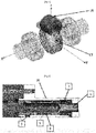
- the Fig. 1 presents an example of an electromechanical tool according to an exemplary embodiment of the invention.
- the tool is a screwing device, or screwdriver 1.
- a screwdriver comprises a casing 2 housing inside the motor means which in this embodiment comprise an electric motor.
- the screwdriver comprises an output shaft 3 which has a first end 5 which extends outside the casing 2. This first end is intended to cooperate with a terminal element which is for example a screwdriver bit or a socket intended to cooperate with an element to screw.
- the output shaft 3 has a second end 6 which is directly connected to the motor shaft or to a reduction means, the latter being connected to the motor shaft.
- the screwdriver comprises control means in the form of a main electronic card 4 which make it possible to control the screwdriver.
- the transmission and in particular the reduction may be such that the output shaft 3 extends perpendicular to the axis of the drive means.
- This screwdriver incorporates a main electronic card which supports the means of control of the screwdriver.
- This main electronic card in particular receives signals from a torque sensor to determine the tightening torque from the measurement of the deformations of the output shaft 3 by means of the gauges. Part 20 of the tool is shown in the Fig. 5 .
- the rotary transformer supplies the on-board card with an electrical voltage produced by the main card of the screwdriver and which, once rectified by the on-board card, supplies the bridge with strain gauges.
- This gauge bridge produces an output signal in the form of a voltage which is transformed into a digital signal by the on-board circuit to then be recovered via the rotary transformer and returned to the main electronic card.
- the frequency of the alternating voltage signal supplying the coil 9 which emits the electromagnetic field is typically between 100 Khz and 200 Khz. Communication is typically carried out at a rate of between 1 Mbits and 2 Mbits per second.
- the matrix can also consist of phenylene polysulfide.
- these plasto-ferrites have a concentration of much lower ferrite than a conventional sintered component whose ferrite proportion is greater than 95% for a permeability of: ⁇ > 100).
- the energy transformation yield is optimal for a ferrite concentration of between 80% and 95% of the total mass of the plasto-ferrite material.
- This value of magnetic permeability is given without unit in fact, it is the multiplication of this value by the magnetic permeability of the vacuum ⁇ 0 (which it is in Henry per meter [H / m]). The result gives the magnetic permeability of the materials.
- the low ferrite content greatly alters the magnetic permeability ( ⁇ varying from 5 to 30). This deficiency is compensated for by a specific winding described later in the description. Furthermore, a low remanence of the transformer is sought so as to maximize the efficiency of the transformer. For this reason, it is necessary to minimize another variable which is the coercive field, that must be between 50 and 1000 A / m
- the transformer traversed by a magnetic field retains its magnetic property unchanged.
- the hysteresis effect as shown in Fig. 2 illustrates this principle.
- the x axis indicates the strength of the magnetic field H and the y axis, the degree of magnetization B.
- This figure clearly shows that the relationship between the field strength (H) and the magnetization (B) n is not linear.
- the initial magnetization curve increases rapidly at the start, then becomes asymptotic when reaching the point of magnetic saturation (Hs).
- Hs point of magnetic saturation
- B the phenomenon of hysteresis.
- the magnetization is shifted from the origin by a value equal to the afterglow.
- there is no magnetic field there is also no (at the beginning) magnetization and the curves are confused from the start.
- the Fig. 3 represents the section of a rotating transformer seen from the front and side view according to an exemplary embodiment.
- the rotary transformer comprises a coil 10 inside the stator 11, and a second coil 12 around the rotor 13.
- the rotary transformer comprises in particular two cores which can be of multiple shapes and placed facing each other. opposite (here in the example illustrated by these two figures: two concentric rings). These two cores are each provided with a coil.
- Each winding sometimes primary, sometimes secondary, generates or collects a magnetic field channeled by the plasto-ferrite cores.
- the section view shown in the Fig. 3 allows you to view the geometry of the magnetic cores and the arrangement of the two windings 10 and 12 facing each other.
- Each coil is made up of enameled wires of a section and a number of turns of specific wires.
- the size of the rings is calculated by the theory of magnetism and simulation.
- plasto-ferrite unlike a more efficient pure ferrite material, the flux density generated is low because of the low coupling ratio.
- the inductance affects by its value the capacity to transmit with the same winding a power signal and a high frequency transmission signal.
- the width of the ranges is chosen so as to satisfy the dual use of the transformer: supply of the electronic card on board the output shaft at a frequency between 100 Khz and 200 Khz and transmission of the signal from the digitized gauge bridge ( conditioned) at high frequency.
- the inductance is dependent on the properties of the core (magnetic permeability, the geometry of the core, the value of the air gap and the characteristics of the coil (number of turns and section of the wire).
- the second stage consists in prototyping and testing because the simulation does not allow an easy assessment of the losses linked to the transformer environment (steel shaft and casing, permeable cover) which degrade the coupling ratios.
- the size of the winding wire is increased within the limit of the size and the minimum inductance criterion.
- the minimum inductance constrains a minimum number of turns.
- the optimization criterion was to reduce losses by increasing the section of the coil wires within the limit of reducing the number of turns.
- the wire diameter initially from 0.11 to 0.15 millimeters is increased to reach a value between 0.25 and 0.35 millimeters.
- the other means of optimization is the use of "taps" which make it possible to specialize the winding according to the mode of use, power supply or data transmission.
- the tapping consists in providing electrical connections between the two ends of the coils allowing a configuration of double winding on the rotor and the stator used according to the functional mode (power supply or high frequency communication).
- This branching allows, in power generation mode for the supply of the secondary circuit, to configure a maximum number of turns.
- This connection also allows, in high frequency communication mode, to increase the communication capacity by reducing the number of turns.
- the Fig. 4 shows a perspective view of the coupling between the rotor and the stator according to another embodiment of a rotary transformer.
- the rotor part 17 remains unchanged with the principle of an O-ring provided with a coil produced by a winding of traditional wire.
- the stator part 16 adopts a “C” shape whose opening allows the passage of the rotor part 17.
- the core of the stator part occupies a prismatic volume which makes it possible to locate the form in a portion of revolution around the tool axis.
- the compactness of the solution is degraded locally in a sector but makes it possible to provide maximum compactness of the solution outside this sector.
- the Fig. 5 shows a sectional view of the part referenced 20 of the tool presented on the Fig. 1 showing the rotor and stator of a rotating transformer according to an exemplary embodiment.
- the output shaft 3 supports an electronic card 12 also driven in rotation. This card is connected to strain gauges measuring the torque.
- the devices proposed comprise different variants, modifications and improvements which will be obvious to those skilled in the art, it being understood that these different variants, modifications and improvements make part of the scope of the invention, as defined by the claims which follow.
- different aspects and characteristics described above can be implemented together, or separately, or else substituted for one another, and all of the different combinations and sub combinations of aspects and characteristics are part of the scope of the 'invention.
- some devices described above may not incorporate all of the modules and functions provided for the embodiments described.
Landscapes
- Engineering & Computer Science (AREA)
- Power Engineering (AREA)
- Mechanical Engineering (AREA)
- Microelectronics & Electronic Packaging (AREA)
- Force Measurement Appropriate To Specific Purposes (AREA)
- Coils Or Transformers For Communication (AREA)
- Arrangements For Transmission Of Measured Signals (AREA)
- Recording Or Reproducing By Magnetic Means (AREA)
Applications Claiming Priority (1)
| Application Number | Priority Date | Filing Date | Title |
|---|---|---|---|
| FR1873880A FR3090439B1 (fr) | 2018-12-21 | 2018-12-21 | outil électroportatif équipé d’un transformateur tournant doté de supports de bobine en plasto-ferrite |
Publications (2)
| Publication Number | Publication Date |
|---|---|
| EP3674036A1 true EP3674036A1 (de) | 2020-07-01 |
| EP3674036B1 EP3674036B1 (de) | 2022-08-31 |
Family
ID=66776489
Family Applications (1)
| Application Number | Title | Priority Date | Filing Date |
|---|---|---|---|
| EP19214571.2A Active EP3674036B1 (de) | 2018-12-21 | 2019-12-09 | Tragbares elektrowerkzeug, das mit einem drehtransformator mit spulenhalterungen aus plastoferrit ausgestattet ist |
Country Status (3)
| Country | Link |
|---|---|
| US (1) | US11571791B2 (de) |
| EP (1) | EP3674036B1 (de) |
| FR (1) | FR3090439B1 (de) |
Families Citing this family (2)
| Publication number | Priority date | Publication date | Assignee | Title |
|---|---|---|---|---|
| US20230124788A1 (en) * | 2019-10-10 | 2023-04-20 | Gary William Box | Rotary Transformer |
| WO2022243010A1 (en) * | 2021-05-17 | 2022-11-24 | Atlas Copco Industrial Technique Ab | A power tool with wireless signal transfer capability |
Citations (12)
| Publication number | Priority date | Publication date | Assignee | Title |
|---|---|---|---|---|
| DE1920890A1 (de) | 1969-04-24 | 1970-11-12 | Guenther Vogeler | Schleifringloser induktiver UEbertrager |
| EP0159825A2 (de) | 1984-04-03 | 1985-10-30 | TRW Transportation Electronics Limited | Drehmomentmessgerät |
| JPS614676A (ja) | 1984-06-15 | 1986-01-10 | ヨコタ工業株式会社 | インパルスレンチの締付トルク制御装置 |
| DE4210201A1 (de) | 1992-03-28 | 1993-09-30 | Gardner Denver Gmbh | Schrauber, insbesondere Druckluftschrauber |
| DE4307131A1 (de) | 1993-03-06 | 1994-09-08 | Albert Kipfelsberger | Kraftschrauber mit elektronischer Drehmomentbegrenzung |
| EP0712105A2 (de) | 1994-11-14 | 1996-05-15 | Clyde L. Ruthroff | Übertragungssystem von elektrischer Energie und Daten |
| DE19637934A1 (de) | 1996-09-17 | 1998-03-26 | Psm Drucklufttechnik Vertrieb | Winkelschrauber mit eingebautem Drehmomentgeber |
| FR2839825A1 (fr) * | 2002-05-17 | 2003-11-21 | Seb Sa | Moteur electrique pour appareil electromenager de preparation culinaire |
| WO2007063106A1 (fr) | 2005-12-01 | 2007-06-07 | Etablissements Georges Renault | Outil de vissage a tete d'angle, incluant un capteur de couple monte sur l'arbre de sortie, et module de transmission correspondant |
| JP2010184329A (ja) | 2009-02-13 | 2010-08-26 | Hitachi Koki Co Ltd | 動力工具 |
| WO2010144048A1 (en) | 2009-06-11 | 2010-12-16 | Atlas Copco Tools Ab | Portable power wrench with a gear casing and a parameter sensing device |
| EP3043458A1 (de) * | 2014-12-31 | 2016-07-13 | Société Électromécanique du Nivernais | Elektrischer rohrmotor |
Family Cites Families (10)
| Publication number | Priority date | Publication date | Assignee | Title |
|---|---|---|---|---|
| DE4214376A1 (de) * | 1992-04-30 | 1993-11-04 | Siemens Matsushita Components | Magnetisches material fuer leistungsuebertragerkerne |
| JP3418827B2 (ja) * | 2000-03-15 | 2003-06-23 | ミネベア株式会社 | Mn−Znフェライトおよびその製造方法 |
| JPWO2006126298A1 (ja) * | 2005-05-23 | 2008-12-25 | 大西 一正 | 円盤状の切断ブレードを備えた切断装置 |
| JPWO2006137453A1 (ja) * | 2005-06-21 | 2009-01-22 | 大西 一正 | 超音波振動を利用する研磨装置 |
| JP2008160973A (ja) * | 2006-12-25 | 2008-07-10 | Mitsuba Corp | ロータ及び回転電機 |
| JP5458343B2 (ja) * | 2007-11-14 | 2014-04-02 | Smc株式会社 | サーボモータ |
| FR3055235B1 (fr) * | 2016-08-23 | 2019-06-28 | Etablissements Georges Renault | Dispositif de vissage a mesure de couple de sortie optimisee, et procede de determination du couple de sortie correspondant |
| CN107026550B (zh) * | 2017-05-19 | 2019-07-02 | 北京航空航天大学 | 一种混合励磁开关磁阻电机 |
| DE102017214776A1 (de) * | 2017-08-23 | 2018-04-26 | Continental Automotive Gmbh | Verfahren zum Fertigen eines Rotors für eine elektrische Maschine mit berührungslosem Leistungsübertragungssystem sowie Rotor, elektrische Maschine und Kraftfahrzeug |
| CN207910558U (zh) * | 2017-12-27 | 2018-09-25 | 曹永辉 | 一种新能源汽车用的高压eps电机 |
-
2018
- 2018-12-21 FR FR1873880A patent/FR3090439B1/fr active Active
-
2019
- 2019-12-09 EP EP19214571.2A patent/EP3674036B1/de active Active
- 2019-12-17 US US16/717,250 patent/US11571791B2/en active Active
Patent Citations (12)
| Publication number | Priority date | Publication date | Assignee | Title |
|---|---|---|---|---|
| DE1920890A1 (de) | 1969-04-24 | 1970-11-12 | Guenther Vogeler | Schleifringloser induktiver UEbertrager |
| EP0159825A2 (de) | 1984-04-03 | 1985-10-30 | TRW Transportation Electronics Limited | Drehmomentmessgerät |
| JPS614676A (ja) | 1984-06-15 | 1986-01-10 | ヨコタ工業株式会社 | インパルスレンチの締付トルク制御装置 |
| DE4210201A1 (de) | 1992-03-28 | 1993-09-30 | Gardner Denver Gmbh | Schrauber, insbesondere Druckluftschrauber |
| DE4307131A1 (de) | 1993-03-06 | 1994-09-08 | Albert Kipfelsberger | Kraftschrauber mit elektronischer Drehmomentbegrenzung |
| EP0712105A2 (de) | 1994-11-14 | 1996-05-15 | Clyde L. Ruthroff | Übertragungssystem von elektrischer Energie und Daten |
| DE19637934A1 (de) | 1996-09-17 | 1998-03-26 | Psm Drucklufttechnik Vertrieb | Winkelschrauber mit eingebautem Drehmomentgeber |
| FR2839825A1 (fr) * | 2002-05-17 | 2003-11-21 | Seb Sa | Moteur electrique pour appareil electromenager de preparation culinaire |
| WO2007063106A1 (fr) | 2005-12-01 | 2007-06-07 | Etablissements Georges Renault | Outil de vissage a tete d'angle, incluant un capteur de couple monte sur l'arbre de sortie, et module de transmission correspondant |
| JP2010184329A (ja) | 2009-02-13 | 2010-08-26 | Hitachi Koki Co Ltd | 動力工具 |
| WO2010144048A1 (en) | 2009-06-11 | 2010-12-16 | Atlas Copco Tools Ab | Portable power wrench with a gear casing and a parameter sensing device |
| EP3043458A1 (de) * | 2014-12-31 | 2016-07-13 | Société Électromécanique du Nivernais | Elektrischer rohrmotor |
Also Published As
| Publication number | Publication date |
|---|---|
| US11571791B2 (en) | 2023-02-07 |
| EP3674036B1 (de) | 2022-08-31 |
| FR3090439A1 (fr) | 2020-06-26 |
| FR3090439B1 (fr) | 2020-12-18 |
| US20200198104A1 (en) | 2020-06-25 |
Similar Documents
| Publication | Publication Date | Title |
|---|---|---|
| EP3674036B1 (de) | Tragbares elektrowerkzeug, das mit einem drehtransformator mit spulenhalterungen aus plastoferrit ausgestattet ist | |
| FR2927681A1 (fr) | Systeme de mesure d'usure de frein | |
| US6788212B2 (en) | Conductor detecting device | |
| KR20070030916A (ko) | 배기가스 터보차저 | |
| EP0221802B1 (de) | Sicherheitswerkzeughalter für Werkzeugmaschine | |
| CN104034301A (zh) | 微小型迎角传感器 | |
| FR3072773A1 (fr) | Capteur de couple pour element en rotation utilisant un couplage mecanique a friction | |
| CN1420597A (zh) | 密闭构造电动机及其使用方法 | |
| EP3955433A1 (de) | Fluidverteiler mit verbesserter funktion | |
| EP0023163A1 (de) | Biegsame Sonde zum zerstörungsfreien Prüfen sehr langer Rohre | |
| FR2831345A1 (fr) | Machine electrique a defluxage mecanique | |
| EP0609645B1 (de) | Elektrischer Asynchronmotor mit hoher Drehgeschwindigkeit und hoher Leistung | |
| EP3867603B1 (de) | Verfahren und sensorsystem zur bestimmung einer relativen winkelposition zwischen zwei teilen und verfahren zur herstellung eines magnetischen elements | |
| US20140000356A1 (en) | Tape Adhesion Test System | |
| WO2010040956A1 (fr) | Dispositif magnetique de determination de position angulaire produisant un signal sinusoïdal et machine electrique tournante polyphasee comprenant un tel dispositif | |
| FR2844591A1 (fr) | Dispositif de determination du deplacement d'un arbre | |
| EP1567870B1 (de) | Geschwindigkeitsaufnehmer für ein bewegliches organ | |
| EP2912345A1 (de) | Vorrichtung zur betätigung eines oder mehrerer beweglicher teile, insbesondere für einen kraftfahrzeug-turbolader | |
| FR3042330A1 (fr) | Direction assistee de vehicule automobile avec un moteur electromagnetique a flux magnetique axial et une alimentation electrique des stators du moteur se faisant en parallele a redondance | |
| EP3244167A1 (de) | Magnetkomponente für hall-effekt-sensor, elektrische einheit und elektrischer aufladekompressor, der eine solche magnetkomponente umfasst | |
| EP1727998B1 (de) | Aktives magnetlager mit automatischer erfassung von dessen position | |
| JP6840970B2 (ja) | 回転速度検出装置付きターボチャージャ | |
| EP0107167B1 (de) | Schlagbolzen hoher Empfindlichkeit | |
| WO2007085772A1 (fr) | Detecteur electromagnetique de vitesse de rotation d'un organe tournant | |
| EP1166295A1 (de) | Verfahren zur positionsbestimmung eines beweglichen elements in mindestens einem hauptluftspalt eines elektromagnetischen aktuators |
Legal Events
| Date | Code | Title | Description |
|---|---|---|---|
| PUAI | Public reference made under article 153(3) epc to a published international application that has entered the european phase |
Free format text: ORIGINAL CODE: 0009012 |
|
| STAA | Information on the status of an ep patent application or granted ep patent |
Free format text: STATUS: THE APPLICATION HAS BEEN PUBLISHED |
|
| STAA | Information on the status of an ep patent application or granted ep patent |
Free format text: STATUS: REQUEST FOR EXAMINATION WAS MADE |
|
| AK | Designated contracting states |
Kind code of ref document: A1 Designated state(s): AL AT BE BG CH CY CZ DE DK EE ES FI FR GB GR HR HU IE IS IT LI LT LU LV MC MK MT NL NO PL PT RO RS SE SI SK SM TR |
|
| AX | Request for extension of the european patent |
Extension state: BA ME |
|
| 17P | Request for examination filed |
Effective date: 20200615 |
|
| RBV | Designated contracting states (corrected) |
Designated state(s): AL AT BE BG CH CY CZ DE DK EE ES FI FR GB GR HR HU IE IS IT LI LT LU LV MC MK MT NL NO PL PT RO RS SE SI SK SM TR |
|
| GRAP | Despatch of communication of intention to grant a patent |
Free format text: ORIGINAL CODE: EPIDOSNIGR1 |
|
| STAA | Information on the status of an ep patent application or granted ep patent |
Free format text: STATUS: GRANT OF PATENT IS INTENDED |
|
| INTG | Intention to grant announced |
Effective date: 20220203 |
|
| GRAJ | Information related to disapproval of communication of intention to grant by the applicant or resumption of examination proceedings by the epo deleted |
Free format text: ORIGINAL CODE: EPIDOSDIGR1 |
|
| STAA | Information on the status of an ep patent application or granted ep patent |
Free format text: STATUS: REQUEST FOR EXAMINATION WAS MADE |
|
| GRAS | Grant fee paid |
Free format text: ORIGINAL CODE: EPIDOSNIGR3 |
|
| STAA | Information on the status of an ep patent application or granted ep patent |
Free format text: STATUS: GRANT OF PATENT IS INTENDED |
|
| GRAP | Despatch of communication of intention to grant a patent |
Free format text: ORIGINAL CODE: EPIDOSNIGR1 |
|
| INTC | Intention to grant announced (deleted) | ||
| INTG | Intention to grant announced |
Effective date: 20220701 |
|
| GRAA | (expected) grant |
Free format text: ORIGINAL CODE: 0009210 |
|
| STAA | Information on the status of an ep patent application or granted ep patent |
Free format text: STATUS: THE PATENT HAS BEEN GRANTED |
|
| AK | Designated contracting states |
Kind code of ref document: B1 Designated state(s): AL AT BE BG CH CY CZ DE DK EE ES FI FR GB GR HR HU IE IS IT LI LT LU LV MC MK MT NL NO PL PT RO RS SE SI SK SM TR |
|
| REG | Reference to a national code |
Ref country code: CH Ref legal event code: EP Ref country code: GB Ref legal event code: FG4D Free format text: NOT ENGLISH |
|
| REG | Reference to a national code |
Ref country code: AT Ref legal event code: REF Ref document number: 1514969 Country of ref document: AT Kind code of ref document: T Effective date: 20220915 Ref country code: DE Ref legal event code: R096 Ref document number: 602019018916 Country of ref document: DE |
|
| REG | Reference to a national code |
Ref country code: IE Ref legal event code: FG4D Free format text: LANGUAGE OF EP DOCUMENT: FRENCH |
|
| REG | Reference to a national code |
Ref country code: LT Ref legal event code: MG9D |
|
| REG | Reference to a national code |
Ref country code: NL Ref legal event code: MP Effective date: 20220831 |
|
| PG25 | Lapsed in a contracting state [announced via postgrant information from national office to epo] |
Ref country code: SE Free format text: LAPSE BECAUSE OF FAILURE TO SUBMIT A TRANSLATION OF THE DESCRIPTION OR TO PAY THE FEE WITHIN THE PRESCRIBED TIME-LIMIT Effective date: 20220831 Ref country code: RS Free format text: LAPSE BECAUSE OF FAILURE TO SUBMIT A TRANSLATION OF THE DESCRIPTION OR TO PAY THE FEE WITHIN THE PRESCRIBED TIME-LIMIT Effective date: 20220831 Ref country code: NO Free format text: LAPSE BECAUSE OF FAILURE TO SUBMIT A TRANSLATION OF THE DESCRIPTION OR TO PAY THE FEE WITHIN THE PRESCRIBED TIME-LIMIT Effective date: 20221130 Ref country code: LV Free format text: LAPSE BECAUSE OF FAILURE TO SUBMIT A TRANSLATION OF THE DESCRIPTION OR TO PAY THE FEE WITHIN THE PRESCRIBED TIME-LIMIT Effective date: 20220831 Ref country code: LT Free format text: LAPSE BECAUSE OF FAILURE TO SUBMIT A TRANSLATION OF THE DESCRIPTION OR TO PAY THE FEE WITHIN THE PRESCRIBED TIME-LIMIT Effective date: 20220831 Ref country code: FI Free format text: LAPSE BECAUSE OF FAILURE TO SUBMIT A TRANSLATION OF THE DESCRIPTION OR TO PAY THE FEE WITHIN THE PRESCRIBED TIME-LIMIT Effective date: 20220831 |
|
| REG | Reference to a national code |
Ref country code: AT Ref legal event code: MK05 Ref document number: 1514969 Country of ref document: AT Kind code of ref document: T Effective date: 20220831 |
|
| PG25 | Lapsed in a contracting state [announced via postgrant information from national office to epo] |
Ref country code: PL Free format text: LAPSE BECAUSE OF FAILURE TO SUBMIT A TRANSLATION OF THE DESCRIPTION OR TO PAY THE FEE WITHIN THE PRESCRIBED TIME-LIMIT Effective date: 20220831 Ref country code: IS Free format text: LAPSE BECAUSE OF FAILURE TO SUBMIT A TRANSLATION OF THE DESCRIPTION OR TO PAY THE FEE WITHIN THE PRESCRIBED TIME-LIMIT Effective date: 20221231 Ref country code: HR Free format text: LAPSE BECAUSE OF FAILURE TO SUBMIT A TRANSLATION OF THE DESCRIPTION OR TO PAY THE FEE WITHIN THE PRESCRIBED TIME-LIMIT Effective date: 20220831 Ref country code: GR Free format text: LAPSE BECAUSE OF FAILURE TO SUBMIT A TRANSLATION OF THE DESCRIPTION OR TO PAY THE FEE WITHIN THE PRESCRIBED TIME-LIMIT Effective date: 20221201 |
|
| PG25 | Lapsed in a contracting state [announced via postgrant information from national office to epo] |
Ref country code: SM Free format text: LAPSE BECAUSE OF FAILURE TO SUBMIT A TRANSLATION OF THE DESCRIPTION OR TO PAY THE FEE WITHIN THE PRESCRIBED TIME-LIMIT Effective date: 20220831 Ref country code: RO Free format text: LAPSE BECAUSE OF FAILURE TO SUBMIT A TRANSLATION OF THE DESCRIPTION OR TO PAY THE FEE WITHIN THE PRESCRIBED TIME-LIMIT Effective date: 20220831 Ref country code: PT Free format text: LAPSE BECAUSE OF FAILURE TO SUBMIT A TRANSLATION OF THE DESCRIPTION OR TO PAY THE FEE WITHIN THE PRESCRIBED TIME-LIMIT Effective date: 20230102 Ref country code: ES Free format text: LAPSE BECAUSE OF FAILURE TO SUBMIT A TRANSLATION OF THE DESCRIPTION OR TO PAY THE FEE WITHIN THE PRESCRIBED TIME-LIMIT Effective date: 20220831 Ref country code: DK Free format text: LAPSE BECAUSE OF FAILURE TO SUBMIT A TRANSLATION OF THE DESCRIPTION OR TO PAY THE FEE WITHIN THE PRESCRIBED TIME-LIMIT Effective date: 20220831 Ref country code: CZ Free format text: LAPSE BECAUSE OF FAILURE TO SUBMIT A TRANSLATION OF THE DESCRIPTION OR TO PAY THE FEE WITHIN THE PRESCRIBED TIME-LIMIT Effective date: 20220831 Ref country code: AT Free format text: LAPSE BECAUSE OF FAILURE TO SUBMIT A TRANSLATION OF THE DESCRIPTION OR TO PAY THE FEE WITHIN THE PRESCRIBED TIME-LIMIT Effective date: 20220831 |
|
| PG25 | Lapsed in a contracting state [announced via postgrant information from national office to epo] |
Ref country code: SK Free format text: LAPSE BECAUSE OF FAILURE TO SUBMIT A TRANSLATION OF THE DESCRIPTION OR TO PAY THE FEE WITHIN THE PRESCRIBED TIME-LIMIT Effective date: 20220831 Ref country code: EE Free format text: LAPSE BECAUSE OF FAILURE TO SUBMIT A TRANSLATION OF THE DESCRIPTION OR TO PAY THE FEE WITHIN THE PRESCRIBED TIME-LIMIT Effective date: 20220831 |
|
| REG | Reference to a national code |
Ref country code: DE Ref legal event code: R097 Ref document number: 602019018916 Country of ref document: DE |
|
| PG25 | Lapsed in a contracting state [announced via postgrant information from national office to epo] |
Ref country code: NL Free format text: LAPSE BECAUSE OF FAILURE TO SUBMIT A TRANSLATION OF THE DESCRIPTION OR TO PAY THE FEE WITHIN THE PRESCRIBED TIME-LIMIT Effective date: 20220831 Ref country code: AL Free format text: LAPSE BECAUSE OF FAILURE TO SUBMIT A TRANSLATION OF THE DESCRIPTION OR TO PAY THE FEE WITHIN THE PRESCRIBED TIME-LIMIT Effective date: 20220831 |
|
| PLBE | No opposition filed within time limit |
Free format text: ORIGINAL CODE: 0009261 |
|
| STAA | Information on the status of an ep patent application or granted ep patent |
Free format text: STATUS: NO OPPOSITION FILED WITHIN TIME LIMIT |
|
| REG | Reference to a national code |
Ref country code: CH Ref legal event code: PL |
|
| 26N | No opposition filed |
Effective date: 20230601 |
|
| REG | Reference to a national code |
Ref country code: BE Ref legal event code: MM Effective date: 20221231 |
|
| PG25 | Lapsed in a contracting state [announced via postgrant information from national office to epo] |
Ref country code: SI Free format text: LAPSE BECAUSE OF FAILURE TO SUBMIT A TRANSLATION OF THE DESCRIPTION OR TO PAY THE FEE WITHIN THE PRESCRIBED TIME-LIMIT Effective date: 20220831 Ref country code: LU Free format text: LAPSE BECAUSE OF NON-PAYMENT OF DUE FEES Effective date: 20221209 |
|
| PG25 | Lapsed in a contracting state [announced via postgrant information from national office to epo] |
Ref country code: LI Free format text: LAPSE BECAUSE OF NON-PAYMENT OF DUE FEES Effective date: 20221231 Ref country code: IE Free format text: LAPSE BECAUSE OF NON-PAYMENT OF DUE FEES Effective date: 20221209 Ref country code: CH Free format text: LAPSE BECAUSE OF NON-PAYMENT OF DUE FEES Effective date: 20221231 |
|
| PG25 | Lapsed in a contracting state [announced via postgrant information from national office to epo] |
Ref country code: BE Free format text: LAPSE BECAUSE OF NON-PAYMENT OF DUE FEES Effective date: 20221231 |
|
| PG25 | Lapsed in a contracting state [announced via postgrant information from national office to epo] |
Ref country code: HU Free format text: LAPSE BECAUSE OF FAILURE TO SUBMIT A TRANSLATION OF THE DESCRIPTION OR TO PAY THE FEE WITHIN THE PRESCRIBED TIME-LIMIT; INVALID AB INITIO Effective date: 20191209 |
|
| PG25 | Lapsed in a contracting state [announced via postgrant information from national office to epo] |
Ref country code: CY Free format text: LAPSE BECAUSE OF FAILURE TO SUBMIT A TRANSLATION OF THE DESCRIPTION OR TO PAY THE FEE WITHIN THE PRESCRIBED TIME-LIMIT Effective date: 20220831 |
|
| PG25 | Lapsed in a contracting state [announced via postgrant information from national office to epo] |
Ref country code: MK Free format text: LAPSE BECAUSE OF FAILURE TO SUBMIT A TRANSLATION OF THE DESCRIPTION OR TO PAY THE FEE WITHIN THE PRESCRIBED TIME-LIMIT Effective date: 20220831 Ref country code: IT Free format text: LAPSE BECAUSE OF FAILURE TO SUBMIT A TRANSLATION OF THE DESCRIPTION OR TO PAY THE FEE WITHIN THE PRESCRIBED TIME-LIMIT Effective date: 20220831 |
|
| PG25 | Lapsed in a contracting state [announced via postgrant information from national office to epo] |
Ref country code: MC Free format text: LAPSE BECAUSE OF FAILURE TO SUBMIT A TRANSLATION OF THE DESCRIPTION OR TO PAY THE FEE WITHIN THE PRESCRIBED TIME-LIMIT Effective date: 20220831 |
|
| PG25 | Lapsed in a contracting state [announced via postgrant information from national office to epo] |
Ref country code: MC Free format text: LAPSE BECAUSE OF FAILURE TO SUBMIT A TRANSLATION OF THE DESCRIPTION OR TO PAY THE FEE WITHIN THE PRESCRIBED TIME-LIMIT Effective date: 20220831 |
|
| PG25 | Lapsed in a contracting state [announced via postgrant information from national office to epo] |
Ref country code: BG Free format text: LAPSE BECAUSE OF FAILURE TO SUBMIT A TRANSLATION OF THE DESCRIPTION OR TO PAY THE FEE WITHIN THE PRESCRIBED TIME-LIMIT Effective date: 20220831 |
|
| PG25 | Lapsed in a contracting state [announced via postgrant information from national office to epo] |
Ref country code: MT Free format text: LAPSE BECAUSE OF FAILURE TO SUBMIT A TRANSLATION OF THE DESCRIPTION OR TO PAY THE FEE WITHIN THE PRESCRIBED TIME-LIMIT Effective date: 20220831 |
|
| PG25 | Lapsed in a contracting state [announced via postgrant information from national office to epo] |
Ref country code: TR Free format text: LAPSE BECAUSE OF FAILURE TO SUBMIT A TRANSLATION OF THE DESCRIPTION OR TO PAY THE FEE WITHIN THE PRESCRIBED TIME-LIMIT Effective date: 20220831 |
|
| PGFP | Annual fee paid to national office [announced via postgrant information from national office to epo] |
Ref country code: DE Payment date: 20251219 Year of fee payment: 7 |
|
| PGFP | Annual fee paid to national office [announced via postgrant information from national office to epo] |
Ref country code: GB Payment date: 20251223 Year of fee payment: 7 |
|
| PGFP | Annual fee paid to national office [announced via postgrant information from national office to epo] |
Ref country code: FR Payment date: 20251218 Year of fee payment: 7 |