EP3674056A1 - Dispositif de moulage par injection, procédé de moulage par injection et matériau de résine pour moulage par injection - Google Patents
Dispositif de moulage par injection, procédé de moulage par injection et matériau de résine pour moulage par injection Download PDFInfo
- Publication number
- EP3674056A1 EP3674056A1 EP18912358.1A EP18912358A EP3674056A1 EP 3674056 A1 EP3674056 A1 EP 3674056A1 EP 18912358 A EP18912358 A EP 18912358A EP 3674056 A1 EP3674056 A1 EP 3674056A1
- Authority
- EP
- European Patent Office
- Prior art keywords
- resin material
- injection molding
- cavity
- high frequency
- injection
- Prior art date
- Legal status (The legal status is an assumption and is not a legal conclusion. Google has not performed a legal analysis and makes no representation as to the accuracy of the status listed.)
- Withdrawn
Links
Images






Classifications
-
- B—PERFORMING OPERATIONS; TRANSPORTING
- B29—WORKING OF PLASTICS; WORKING OF SUBSTANCES IN A PLASTIC STATE IN GENERAL
- B29C—SHAPING OR JOINING OF PLASTICS; SHAPING OF MATERIAL IN A PLASTIC STATE, NOT OTHERWISE PROVIDED FOR; AFTER-TREATMENT OF THE SHAPED PRODUCTS, e.g. REPAIRING
- B29C45/00—Injection moulding, i.e. forcing the required volume of moulding material through a nozzle into a closed mould; Apparatus therefor
- B29C45/17—Component parts, details or accessories; Auxiliary operations
- B29C45/72—Heating or cooling
- B29C45/73—Heating or cooling of the mould
-
- B—PERFORMING OPERATIONS; TRANSPORTING
- B29—WORKING OF PLASTICS; WORKING OF SUBSTANCES IN A PLASTIC STATE IN GENERAL
- B29C—SHAPING OR JOINING OF PLASTICS; SHAPING OF MATERIAL IN A PLASTIC STATE, NOT OTHERWISE PROVIDED FOR; AFTER-TREATMENT OF THE SHAPED PRODUCTS, e.g. REPAIRING
- B29C45/00—Injection moulding, i.e. forcing the required volume of moulding material through a nozzle into a closed mould; Apparatus therefor
- B29C45/17—Component parts, details or accessories; Auxiliary operations
- B29C45/76—Measuring, controlling or regulating
- B29C45/7646—Measuring, controlling or regulating viscosity
-
- B—PERFORMING OPERATIONS; TRANSPORTING
- B29—WORKING OF PLASTICS; WORKING OF SUBSTANCES IN A PLASTIC STATE IN GENERAL
- B29C—SHAPING OR JOINING OF PLASTICS; SHAPING OF MATERIAL IN A PLASTIC STATE, NOT OTHERWISE PROVIDED FOR; AFTER-TREATMENT OF THE SHAPED PRODUCTS, e.g. REPAIRING
- B29C33/00—Moulds or cores; Details thereof or accessories therefor
- B29C33/02—Moulds or cores; Details thereof or accessories therefor with incorporated heating or cooling means
- B29C33/08—Moulds or cores; Details thereof or accessories therefor with incorporated heating or cooling means for dielectric heating
-
- B—PERFORMING OPERATIONS; TRANSPORTING
- B29—WORKING OF PLASTICS; WORKING OF SUBSTANCES IN A PLASTIC STATE IN GENERAL
- B29C—SHAPING OR JOINING OF PLASTICS; SHAPING OF MATERIAL IN A PLASTIC STATE, NOT OTHERWISE PROVIDED FOR; AFTER-TREATMENT OF THE SHAPED PRODUCTS, e.g. REPAIRING
- B29C45/00—Injection moulding, i.e. forcing the required volume of moulding material through a nozzle into a closed mould; Apparatus therefor
- B29C45/0001—Injection moulding, i.e. forcing the required volume of moulding material through a nozzle into a closed mould; Apparatus therefor characterised by the choice of material
-
- B—PERFORMING OPERATIONS; TRANSPORTING
- B29—WORKING OF PLASTICS; WORKING OF SUBSTANCES IN A PLASTIC STATE IN GENERAL
- B29C—SHAPING OR JOINING OF PLASTICS; SHAPING OF MATERIAL IN A PLASTIC STATE, NOT OTHERWISE PROVIDED FOR; AFTER-TREATMENT OF THE SHAPED PRODUCTS, e.g. REPAIRING
- B29C45/00—Injection moulding, i.e. forcing the required volume of moulding material through a nozzle into a closed mould; Apparatus therefor
- B29C45/03—Injection moulding apparatus
-
- B—PERFORMING OPERATIONS; TRANSPORTING
- B29—WORKING OF PLASTICS; WORKING OF SUBSTANCES IN A PLASTIC STATE IN GENERAL
- B29C—SHAPING OR JOINING OF PLASTICS; SHAPING OF MATERIAL IN A PLASTIC STATE, NOT OTHERWISE PROVIDED FOR; AFTER-TREATMENT OF THE SHAPED PRODUCTS, e.g. REPAIRING
- B29C45/00—Injection moulding, i.e. forcing the required volume of moulding material through a nozzle into a closed mould; Apparatus therefor
- B29C45/17—Component parts, details or accessories; Auxiliary operations
- B29C45/76—Measuring, controlling or regulating
- B29C45/77—Measuring, controlling or regulating of velocity or pressure of moulding material
-
- B—PERFORMING OPERATIONS; TRANSPORTING
- B29—WORKING OF PLASTICS; WORKING OF SUBSTANCES IN A PLASTIC STATE IN GENERAL
- B29C—SHAPING OR JOINING OF PLASTICS; SHAPING OF MATERIAL IN A PLASTIC STATE, NOT OTHERWISE PROVIDED FOR; AFTER-TREATMENT OF THE SHAPED PRODUCTS, e.g. REPAIRING
- B29C45/00—Injection moulding, i.e. forcing the required volume of moulding material through a nozzle into a closed mould; Apparatus therefor
- B29C45/17—Component parts, details or accessories; Auxiliary operations
- B29C45/76—Measuring, controlling or regulating
- B29C45/78—Measuring, controlling or regulating of temperature
-
- C—CHEMISTRY; METALLURGY
- C08—ORGANIC MACROMOLECULAR COMPOUNDS; THEIR PREPARATION OR CHEMICAL WORKING-UP; COMPOSITIONS BASED THEREON
- C08L—COMPOSITIONS OF MACROMOLECULAR COMPOUNDS
- C08L23/00—Compositions of homopolymers or copolymers of unsaturated aliphatic hydrocarbons having only one carbon-to-carbon double bond; Compositions of derivatives of such polymers
- C08L23/02—Compositions of homopolymers or copolymers of unsaturated aliphatic hydrocarbons having only one carbon-to-carbon double bond; Compositions of derivatives of such polymers not modified by chemical after-treatment
- C08L23/04—Homopolymers or copolymers of ethene
- C08L23/06—Polyethylene
-
- C—CHEMISTRY; METALLURGY
- C08—ORGANIC MACROMOLECULAR COMPOUNDS; THEIR PREPARATION OR CHEMICAL WORKING-UP; COMPOSITIONS BASED THEREON
- C08L—COMPOSITIONS OF MACROMOLECULAR COMPOUNDS
- C08L23/00—Compositions of homopolymers or copolymers of unsaturated aliphatic hydrocarbons having only one carbon-to-carbon double bond; Compositions of derivatives of such polymers
- C08L23/02—Compositions of homopolymers or copolymers of unsaturated aliphatic hydrocarbons having only one carbon-to-carbon double bond; Compositions of derivatives of such polymers not modified by chemical after-treatment
- C08L23/10—Homopolymers or copolymers of propene
- C08L23/12—Polypropene
-
- C—CHEMISTRY; METALLURGY
- C08—ORGANIC MACROMOLECULAR COMPOUNDS; THEIR PREPARATION OR CHEMICAL WORKING-UP; COMPOSITIONS BASED THEREON
- C08L—COMPOSITIONS OF MACROMOLECULAR COMPOUNDS
- C08L25/00—Compositions of, homopolymers or copolymers of compounds having one or more unsaturated aliphatic radicals, each having only one carbon-to-carbon double bond, and at least one being terminated by an aromatic carbocyclic ring; Compositions of derivatives of such polymers
- C08L25/02—Homopolymers or copolymers of hydrocarbons
- C08L25/04—Homopolymers or copolymers of styrene
- C08L25/06—Polystyrene
-
- C—CHEMISTRY; METALLURGY
- C08—ORGANIC MACROMOLECULAR COMPOUNDS; THEIR PREPARATION OR CHEMICAL WORKING-UP; COMPOSITIONS BASED THEREON
- C08L—COMPOSITIONS OF MACROMOLECULAR COMPOUNDS
- C08L33/00—Compositions of homopolymers or copolymers of compounds having one or more unsaturated aliphatic radicals, each having only one carbon-to-carbon double bond, and only one being terminated by only one carboxyl radical, or of salts, anhydrides, esters, amides, imides or nitriles thereof; Compositions of derivatives of such polymers
- C08L33/04—Homopolymers or copolymers of esters
- C08L33/06—Homopolymers or copolymers of esters of esters containing only carbon, hydrogen and oxygen, which oxygen atoms are present only as part of the carboxyl radical
- C08L33/10—Homopolymers or copolymers of methacrylic acid esters
- C08L33/12—Homopolymers or copolymers of methyl methacrylate
-
- C—CHEMISTRY; METALLURGY
- C08—ORGANIC MACROMOLECULAR COMPOUNDS; THEIR PREPARATION OR CHEMICAL WORKING-UP; COMPOSITIONS BASED THEREON
- C08L—COMPOSITIONS OF MACROMOLECULAR COMPOUNDS
- C08L77/00—Compositions of polyamides obtained by reactions forming a carboxylic amide link in the main chain; Compositions of derivatives of such polymers
- C08L77/06—Polyamides derived from polyamines and polycarboxylic acids
-
- H—ELECTRICITY
- H05—ELECTRIC TECHNIQUES NOT OTHERWISE PROVIDED FOR
- H05B—ELECTRIC HEATING; ELECTRIC LIGHT SOURCES NOT OTHERWISE PROVIDED FOR; CIRCUIT ARRANGEMENTS FOR ELECTRIC LIGHT SOURCES, IN GENERAL
- H05B6/00—Heating by electric, magnetic or electromagnetic fields
- H05B6/46—Dielectric heating
- H05B6/62—Apparatus for specific applications
-
- B—PERFORMING OPERATIONS; TRANSPORTING
- B29—WORKING OF PLASTICS; WORKING OF SUBSTANCES IN A PLASTIC STATE IN GENERAL
- B29C—SHAPING OR JOINING OF PLASTICS; SHAPING OF MATERIAL IN A PLASTIC STATE, NOT OTHERWISE PROVIDED FOR; AFTER-TREATMENT OF THE SHAPED PRODUCTS, e.g. REPAIRING
- B29C2945/00—Indexing scheme relating to injection moulding, i.e. forcing the required volume of moulding material through a nozzle into a closed mould
- B29C2945/76—Measuring, controlling or regulating
- B29C2945/76003—Measured parameter
- B29C2945/76006—Pressure
-
- B—PERFORMING OPERATIONS; TRANSPORTING
- B29—WORKING OF PLASTICS; WORKING OF SUBSTANCES IN A PLASTIC STATE IN GENERAL
- B29C—SHAPING OR JOINING OF PLASTICS; SHAPING OF MATERIAL IN A PLASTIC STATE, NOT OTHERWISE PROVIDED FOR; AFTER-TREATMENT OF THE SHAPED PRODUCTS, e.g. REPAIRING
- B29C2945/00—Indexing scheme relating to injection moulding, i.e. forcing the required volume of moulding material through a nozzle into a closed mould
- B29C2945/76—Measuring, controlling or regulating
- B29C2945/76003—Measured parameter
- B29C2945/76033—Electric current or voltage
-
- B—PERFORMING OPERATIONS; TRANSPORTING
- B29—WORKING OF PLASTICS; WORKING OF SUBSTANCES IN A PLASTIC STATE IN GENERAL
- B29C—SHAPING OR JOINING OF PLASTICS; SHAPING OF MATERIAL IN A PLASTIC STATE, NOT OTHERWISE PROVIDED FOR; AFTER-TREATMENT OF THE SHAPED PRODUCTS, e.g. REPAIRING
- B29C2945/00—Indexing scheme relating to injection moulding, i.e. forcing the required volume of moulding material through a nozzle into a closed mould
- B29C2945/76—Measuring, controlling or regulating
- B29C2945/76003—Measured parameter
- B29C2945/7604—Temperature
-
- B—PERFORMING OPERATIONS; TRANSPORTING
- B29—WORKING OF PLASTICS; WORKING OF SUBSTANCES IN A PLASTIC STATE IN GENERAL
- B29C—SHAPING OR JOINING OF PLASTICS; SHAPING OF MATERIAL IN A PLASTIC STATE, NOT OTHERWISE PROVIDED FOR; AFTER-TREATMENT OF THE SHAPED PRODUCTS, e.g. REPAIRING
- B29C2945/00—Indexing scheme relating to injection moulding, i.e. forcing the required volume of moulding material through a nozzle into a closed mould
- B29C2945/76—Measuring, controlling or regulating
- B29C2945/76344—Phase or stage of measurement
- B29C2945/76381—Injection
-
- B—PERFORMING OPERATIONS; TRANSPORTING
- B29—WORKING OF PLASTICS; WORKING OF SUBSTANCES IN A PLASTIC STATE IN GENERAL
- B29C—SHAPING OR JOINING OF PLASTICS; SHAPING OF MATERIAL IN A PLASTIC STATE, NOT OTHERWISE PROVIDED FOR; AFTER-TREATMENT OF THE SHAPED PRODUCTS, e.g. REPAIRING
- B29C2945/00—Indexing scheme relating to injection moulding, i.e. forcing the required volume of moulding material through a nozzle into a closed mould
- B29C2945/76—Measuring, controlling or regulating
- B29C2945/76344—Phase or stage of measurement
- B29C2945/76414—Solidification, setting phase
-
- B—PERFORMING OPERATIONS; TRANSPORTING
- B29—WORKING OF PLASTICS; WORKING OF SUBSTANCES IN A PLASTIC STATE IN GENERAL
- B29C—SHAPING OR JOINING OF PLASTICS; SHAPING OF MATERIAL IN A PLASTIC STATE, NOT OTHERWISE PROVIDED FOR; AFTER-TREATMENT OF THE SHAPED PRODUCTS, e.g. REPAIRING
- B29C2945/00—Indexing scheme relating to injection moulding, i.e. forcing the required volume of moulding material through a nozzle into a closed mould
- B29C2945/76—Measuring, controlling or regulating
- B29C2945/76494—Controlled parameter
- B29C2945/76498—Pressure
-
- B—PERFORMING OPERATIONS; TRANSPORTING
- B29—WORKING OF PLASTICS; WORKING OF SUBSTANCES IN A PLASTIC STATE IN GENERAL
- B29C—SHAPING OR JOINING OF PLASTICS; SHAPING OF MATERIAL IN A PLASTIC STATE, NOT OTHERWISE PROVIDED FOR; AFTER-TREATMENT OF THE SHAPED PRODUCTS, e.g. REPAIRING
- B29C2945/00—Indexing scheme relating to injection moulding, i.e. forcing the required volume of moulding material through a nozzle into a closed mould
- B29C2945/76—Measuring, controlling or regulating
- B29C2945/76494—Controlled parameter
- B29C2945/76531—Temperature
-
- B—PERFORMING OPERATIONS; TRANSPORTING
- B29—WORKING OF PLASTICS; WORKING OF SUBSTANCES IN A PLASTIC STATE IN GENERAL
- B29C—SHAPING OR JOINING OF PLASTICS; SHAPING OF MATERIAL IN A PLASTIC STATE, NOT OTHERWISE PROVIDED FOR; AFTER-TREATMENT OF THE SHAPED PRODUCTS, e.g. REPAIRING
- B29C2945/00—Indexing scheme relating to injection moulding, i.e. forcing the required volume of moulding material through a nozzle into a closed mould
- B29C2945/76—Measuring, controlling or regulating
- B29C2945/76494—Controlled parameter
- B29C2945/76538—Viscosity
-
- B—PERFORMING OPERATIONS; TRANSPORTING
- B29—WORKING OF PLASTICS; WORKING OF SUBSTANCES IN A PLASTIC STATE IN GENERAL
- B29C—SHAPING OR JOINING OF PLASTICS; SHAPING OF MATERIAL IN A PLASTIC STATE, NOT OTHERWISE PROVIDED FOR; AFTER-TREATMENT OF THE SHAPED PRODUCTS, e.g. REPAIRING
- B29C2945/00—Indexing scheme relating to injection moulding, i.e. forcing the required volume of moulding material through a nozzle into a closed mould
- B29C2945/76—Measuring, controlling or regulating
- B29C2945/76929—Controlling method
- B29C2945/76933—The operating conditions are corrected immediately, during the same phase or cycle
-
- B—PERFORMING OPERATIONS; TRANSPORTING
- B29—WORKING OF PLASTICS; WORKING OF SUBSTANCES IN A PLASTIC STATE IN GENERAL
- B29K—INDEXING SCHEME ASSOCIATED WITH SUBCLASSES B29B, B29C OR B29D, RELATING TO MOULDING MATERIALS OR TO MATERIALS FOR MOULDS, REINFORCEMENTS, FILLERS OR PREFORMED PARTS, e.g. INSERTS
- B29K2077/00—Use of PA, i.e. polyamides, e.g. polyesteramides or derivatives thereof, as moulding material
-
- B—PERFORMING OPERATIONS; TRANSPORTING
- B29—WORKING OF PLASTICS; WORKING OF SUBSTANCES IN A PLASTIC STATE IN GENERAL
- B29K—INDEXING SCHEME ASSOCIATED WITH SUBCLASSES B29B, B29C OR B29D, RELATING TO MOULDING MATERIALS OR TO MATERIALS FOR MOULDS, REINFORCEMENTS, FILLERS OR PREFORMED PARTS, e.g. INSERTS
- B29K2471/00—Use of polyethers, e.g. PEEK, i.e. polyether-etherketone or PEK, i.e. polyetherketone or derivatives thereof, as filler
-
- B—PERFORMING OPERATIONS; TRANSPORTING
- B29—WORKING OF PLASTICS; WORKING OF SUBSTANCES IN A PLASTIC STATE IN GENERAL
- B29K—INDEXING SCHEME ASSOCIATED WITH SUBCLASSES B29B, B29C OR B29D, RELATING TO MOULDING MATERIALS OR TO MATERIALS FOR MOULDS, REINFORCEMENTS, FILLERS OR PREFORMED PARTS, e.g. INSERTS
- B29K2995/00—Properties of moulding materials, reinforcements, fillers, preformed parts or moulds
- B29K2995/0003—Properties of moulding materials, reinforcements, fillers, preformed parts or moulds having particular electrical or magnetic properties, e.g. piezoelectric
- B29K2995/0006—Dielectric
Definitions
- the present disclosure relates to an injection molding device, an injection molding method, and an injection molding resin material.
- An injection molding device is a device for manufacturing a resin product by injecting a resin material having fluidity into a molding die, and solidifying the resin material filled in the molding die. Such an injection molding device has been widely used.
- Patent Literature 1 discloses an injection molding device which is provided with a resin melting device including a high frequency oscillator, and is configured to manufacture a resin product by injecting a resin material having fluidity in the resin melting device into a molding die, and lowering a temperature of resin within the molding die.
- Patent Literature 2 discloses a configuration in which a heater is mounted on a molding die, and fluidity of a resin material injected into the molding die is secured. Thus, it is possible to secure fluidity of a resin material within the molding die, thereby enabling to enhance product quality of a resin product.
- Patent Literature 2 it is necessary to heat and cool the entirety of the molding die in order to solidify a resin material filled in the molding die. This makes the takt time long, and lowers energy efficiency. In view of the above, there is room for improvement in the technique disclosed in Patent Literature 2 in the aspect of production efficiency.
- an object of the present disclosure is to provide an injection molding device, an injection molding method, and an injection molding resin material, which enable to manufacture a high-quality resin product by securing high fluidity of a resin material within a molding die, and enable to reduce the production cost.
- An injection molding device includes: an injection machine which injects a resin material in which a dielectric heat generating material is mixed, while keeping fluidity by temperature control; a molding die which includes a cavity being a channel of flow of the resin material, and a pair of electrodes, each of which faces the cavity, the pair of electrodes being disposed to sandwich the resin material therebetween in a direction crossing a direction of the flow; and a high frequency oscillation device which applies a high frequency alternate-current voltage to the pair of electrodes.
- a configuration of an injection molding device 1 according to the present embodiment is described with reference to FIG. 1 .
- the injection molding device 1 includes a molding die 10, an injection unit (injection machine) 20, a high frequency oscillation unit (high frequency oscillation device) 30, and a controller 60.
- the molding die 10 includes a movable die 11 and a fixed die 12, and a cavity 10a is formed between the movable die 11 and the fixed die 12.
- the movable die 11 can be mold clamped to and separated from the fixed die 12 by an unillustrated driving mechanism.
- the movable die 11 includes a die body 111 made of a metal material, an electrode 112 mounted on the die body 111 in such a way as to face the cavity 10a, and an insulator 113 interposed between the die body 111 and the electrode 112.
- a cooling pipe 114 through which coolant (cooling medium) flows is embedded in the electrode 112.
- the fixed die 12 includes a die body 121 made of a metal material, an electrode 122 mounted on the die body 121 in such a way as to face the cavity 10a, and an insulator 123 interposed between the die body 121 and the electrode 122.
- a cooling pipe 124 through which coolant (cooling medium) flows is embedded in the electrode 122.
- the electrode 112 and the electrode 122 are disposed in such a way as to face each other and to sandwich in the cavity 10a between. And, the insulator 113 or the insulator 123 is sandwiched between the electrode 112 and the electrode 122 in a state that the movable die 11 is mold clamped to the fixed die 12.
- Each of the insulator 113 and the insulator123 is made of a silicate binder or ceramics, for example.
- the injection unit 20 includes a cylinder 21, a screw 22, an injection cylinder 23, a nozzle 24, and a cylinder heater 25.
- the nozzle 24 communicates with the cavity 10a of the molding die 10.
- a resin material supplied from a hopper (not illustrated) into the cylinder 21 is fluidized by heat from the cylinder heater 25, and injected into the cavity 10a through the nozzle 24, as the screw 22 is advanced by driving of the injection cylinder 23.
- the high frequency oscillation unit 30 is a unit which applies a high frequency alternate-current voltage between the electrode 112 and the electrode 122, and includes a power supply 31, an oscillator 32, a matching device 33, and power supply lines 34 and 35.
- a frequency of a high frequency alternate-current voltage to be generated between the electrodes 112 and 122 by the high frequency oscillation unit 30 is set to 27 MHz, as one example.
- an earth leakage circuit breaking valve 41 is disposed at a midway of a power supply path of the power supply line 34, and an earth leakage circuit breaking valve 42 is disposed at a midway of a power supply path of the power supply line 35. Further, a portion of the power supply line 35 close to the electrode 112 with respect to the location where the earth leakage circuit breaking valve 42 is disposed is grounded.
- the controller 60 executes driving control of the injection cylinder 23 and the cylinder heater 25, control of the high frequency oscillation unit 30, and the like.
- the control unit 60 is configured to include a computer provided with a CPU, various programs to be executed on the CPU (including a basic control program such as an OS, and various application programs activated on the OS for executing a specific function), and a memory such as a ROM and a RAM which stores a program and various pieces of data, for example, although detailed illustration thereof is omitted.
- coolant circulation units (cooling medium supply devices) 51 and 52 which circulate coolant (cooling medium) to the cooling pipes 114 and 124, are connected to the injection molding device 1.
- Earth leakage circuit breaking valves 43 to 46 are disposed in coolant circulation channels between the coolant circulation units 51 and 52, and the movable die 11 and the fixed die 12.
- the injection molding device 1 includes a temperature sensor 71 for detecting a temperature of the electrode 112, a temperature sensor 72 for detecting a temperature of the electrode 122, and a temperature sensor 73 for detecting a temperature of a resin material within the cylinder 21.
- the temperature sensors 71 to 73 successively output, during driving of the injection molding device 1, detected temperature data to the controller 60.
- the controller 60 which has received the temperature data, feedback controls the cylinder heater 25 and the high frequency oscillation unit 30 using the data.
- FIG. 2 is a schematic cross-sectional view enlargedly illustrating a part of a configuration of the molding die 10.
- the resin material 70 for use in the injection molding device 1 according to the present embodiment is a resin material in which a dielectric heat generating material is mixed. Details of the resin material 70 will be described later.
- the electrode 112 and the electrode 122 are formed in such a way as to face the cavity 10a. Therefore, the high frequency alternate-current voltage E is applied to the resin material 70, which is introduced into the cavity 10a and flows within the cavity 10a, as illustrated by the arrows.
- the resin material 70 Since a dielectric heat generating material is mixed in the resin material 70, the resin material 70 is heated when the high frequency alternate-current voltage E is applied to the resin material 70. Therefore, fluidity of the resin material 70 within the cavity 10a is retained in a state that the high frequency alternate-current voltage E is applied.
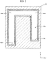
- FIG. 3 is a schematic diagram illustrating a configuration of the cavity 10a formed in the molding die 10.
- a shape of the cavity 10a of the molding die 10 is a substantially U-shape in a plan view, wherein the cavity 10a has two bent portions 10d and 10e between a flow start portion 10b and a flow end portion 10c.
- the resin material 70 which is injected through the nozzle 24 of the injection unit 20, flows from the flow start portion 10b to the flow end portion 10c via the bent portions 10d and 10e.
- the electrodes 112 and 122 extend over the entire area of a flow channel of the resin material 70 from the flow start portion 10b to the flow end portion 10c. Specifically, it is configured such that the high frequency alternate-current voltage E can be applied to the resin material 70 flowing in the cavity 10a of the molding die 10 from the flow start portion 10c until the flow end portion 10c.
- FIG. 4 is a schematic diagram illustrating a principle of the heat generation of the resin material 70.
- the resin material 70 for use in the injection molding device 1 according to the present embodiment is a resin material such that a dielectric heat generating material 702 is mixed in a base material 701.
- a base material 701 it is possible to employ thermoplastic resin such as polyolefin resin or polyamide resin.
- the dielectric heat generating material 702 it is possible to employ a resin material having a structure formed by polymerizing polyolefin monomer or polyamide monomer, and polyether monomer. A detailed structure of the resin material 70 will be described later.
- the resin material 70 within the cavity 10a is heated by application of the high frequency alternate-current voltage E.
- FIG. 5 is a time chart illustrating an application timing of a high frequency alternate-current voltage and an injection pressure to be applied by the controller 60 in injection molding using the injection molding device 1 with respect to time.
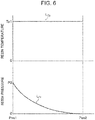
- FIG. 6 is a characteristic diagram illustrating a temperature and a pressure of the resin material 70 within the cavity 10a, when injection is performed.
- FIG. 7 is a characteristic diagram illustrating a temperature and a pressure of the resin material 70, when the pressure is retained after the resin material 70 is filled in the cavity 10a.
- the controller 60 instructs the high frequency oscillation unit 30 to apply the high frequency alternate-current voltage E between the electrodes 112 and 122.
- the controller 60 instructs the injection unit 20 to increase an injection pressure LP to P1.
- the injection pressure LP is increased in such a way as to reach the pressure P1 at a timing T2.
- the controller 60 instructs the cylinder heater 25 to turn on, so that the resin material 70 within the cylinder 21 is brought to a fluidized state.
- the controller 60 instructs the high frequency oscillation unit 30 to retain the high frequency alternate-current voltage E of a predetermined value LE, which is fixed during a period from the timing T1 until the timing T2; and instructs the injection unit 20 to apply a constant injection pressure P2 for a predetermined time until a timing T3.
- a period from the timing T2 until the timing T3 illustrated in FIG. 5 is referred to as a pressure retaining period.
- a temperature LTp of the resin material 70 is kept at a constant temperature Tp1 at which the resin material 70 has fluidity by application of the high frequency alternate-current voltage E of the predetermined value LE in an entire range from a flow start portion Pos1 (equivalent to the above-described flow start portion 10b) until a flow end portion Pos2 (equivalent to the above-described flow end portion 10c) within the cavity 10a.
- a pressure LPr of the resin material 70 within the cavity 10a is a pressure P3 at the flow start portion Pos1, and the pressure LPr gradually decreases toward the flow end portion Pos2.
- the temperature LTp of the resin material 70 within the cavity 10a is kept at the temperature Tp1, since application of the high frequency alternate-current voltage E of the predetermined value LE is continued.
- the pressure LPr of the resin material 70 within the cavity 10a is substantially kept at the constant pressure P2 in the entire range from the flow start portion Pos1 until the flow end portion Pos2 within the cavity 10a, since driving of the injection unit 20 is continued.
- the resin material 70 containing the base material 701 and the dielectric heat generating material 702 is used.
- a composition of the resin material 70 is described with reference to FIG. 8.
- FIG. 8 is a chemical formula of the dielectric heat generating material 702.
- Polyolefin resin selected from among HIPS (high impact polystyrene), PP (polypropylene), LDPE (low-density polyethylene), HDPE (high-density polyethylene), m-PPE (modified polyphenylene ether), and PMMA (acryl)
- A represents polyolefin monomer
- B represents polyether monomer.
- the dielectric heat generating material 702 which is a resin material formed by polymerizing polyolefin monomer and polyether monomer, and in which cations are held on a polyether moiety, is employed.
- Polyamide resin selected from among ABS (acrylonitrile/butadiene/styrene copolymer synthetic resin), PC/ABS (polycarbonate/acrylonitrilelbutadiene/styrene mixed resin), PC (polycarbonate), POM (polyacetal), PA6 (polyamide 6), PA12 (polyamide 12), and PA66 (polyamide 66)
- A represents polyamide monomer
- B represents polyether monomer
- the dielectric heat generating material 702 which is a resin material formed by polymerizing polyamide monomer and polyether monomer, and in which cations are held on a polyether moiety, is employed.
- FIG. 9A is a schematic diagram illustrating a state of the dielectric heat generating material 702 immediately after application of the high frequency alternate-current voltage E is started.
- FIG. 9B is a schematic diagram illustrating a state after a cation M+ of the dielectric heat generating material 702 migrates by application of the high frequency alternate-current voltage E.
- the electromagnetic wave WR When the high frequency alternate-current voltage E is applied to the resin material 70 containing the dielectric heat generating material 702, the electromagnetic wave WR also propagates to the dielectric heat generating material 702 (see FIG. 4 ), and a cation M+, which is present at a position illustrated in FIG. 9A , migrates as illustrated in FIG. 9B .
- Temperature of the resin material 70 for use in injection molding of the injection molding device 1 according to the present embodiment increases due to application of the high frequency alternate-current voltage E, and fluidity thereof is retained.
- thermoplastic resin material is employed as one example of the resin material 70.
- the technique according to the present disclosure is not limited to the above.
- a thermoset resin material may be employed. When a thermoset resin material is injected, a high frequency alternate-current voltage may be applied in curing the resin material.
- fluidity of the resin material 70 flowing within the cavity 10a is retained by dielectric heating.
- one injection unit 20 is connected to the molding die 10.
- the technique according to the present disclosure is not limited to the above. It is possible to retain a temperature of a resin material flowing within a cavity to a substantially same value in the entire region of the cavity. Hence, even when two or more injection units are connected, a hairline defect is hard to occur, and it is possible to provide an enhanced external appearance.
- the molding die 10 is constituted by combining one fixed die 12 and one movable die 11.
- the technique according to the present disclosure is not limited to the above.
- the pair of electrodes 112 and 122 are disposed in a region from the flow start portion 10b to the flow end portion 10c of the cavity 10a in the molding die 10.
- the technique according to the present disclosure is not limited to the above.
- a plurality of pairs of electrodes may be disposed to be away from one another in a flow direction of a resin material within a cavity.
- an electrode pair may not be disposed at a location where electric discharge in air is likely to occur due to a shape of a cavity, and the like.
- An injection molding device includes: an injection machine which injects a resin material in which a dielectric heat generating material is mixed, while keeping fluidity by temperature control; a molding die which includes a cavity being a channel of flow of the resin material, and a pair of electrodes, each of which faces the cavity, the pair of electrodes being disposed to sandwich the resin material therebetween in a direction crossing a direction of the flow; and a high frequency oscillation device which applies a high frequency alternate-current voltage between the pair of electrodes.
- a resin material in which a dielectric heat generating material is mixed, is used as the resin material to be injected, and the pair of electrodes, each of which faces the cavity, are provided and a high frequency alternate-current voltage is applied between the pair of electrodes. Therefore, in the injection molding device according to the above aspect, it is possible to control application of a high frequency alternate-current voltage to the resin material injected from the injection machine and flowing within the cavity. High fluidity is secured for the resin material by application control of a high frequency alternate-current voltage.
- the dielectric heat generating material When a resin material, in which a base material is thermoplastic, is used as the resin material to be injected, the dielectric heat generating material generates heat by applying a high frequency alternate-current voltage to the resin material flowing in the cavity. This enables to secure fluidity of the resin material.
- fluidity is secured not by heating the entirety of the molding die, but by temperature control of the resin material flowing within the cavity.
- temperature control of the resin material flowing within the cavity it is possible to reduce energy loss, and to solidify the resin material only by application control of a high frequency alternate-current voltage after the cavity is filled with the resin material. Accordingly, as compared with a case of temperature control of the entirety of the molding die, it is also possible to shorten the tact time.
- the injection molding device it is possible to manufacture a high-quality resin product and to reduce the production cost, by securing high fluidity of the resin material within the molding die.
- an injection molding device is such that the molding die includes a fixed die and a movable die, each of which has a die body and which fit into each other, and that one of the pair of electrodes is mounted on the die body of the fixed die via an insulator, and another of the pair of electrodes is mounted on the die body of the movable die via an insulator.
- an electrode is mounted on each of the fixed die and the movable die in a state that an insulator is sandwiched between the electrode and a die body. Hence, it is possible to suppress leakage of an electromagnetic wave to the outside of the die, when a high frequency alternate-current voltage is applied.
- an injection molding device is such that at least one of the pair of electrodes has a cooling channel through which a cooling medium passes, and the injection molding device further includes a cooling medium supply device which supplies the cooling medium to the cooling channel.
- the electrode since the electrode has a cooling channel, even when heat of the resin material by dielectric heat generation is transmitted to the electrode, it is possible to cool the electrode by supply of a cooling medium. Therefore, in the injection molding device according to the above aspect, it is possible to more accurately perform temperature control of the resin material flowing within the cavity, to cool the resin material and the molding die by supply of the cooling medium in solidifying the resin material and taking the resin material from the molding die, and to shorten the tact time. Therefore, the injection molding device according to the above aspect is advantageous in achieving higher productivity.
- an injection molding device is such that the pair of electrodes are formed from an upstream end of the cavity until a downstream end of the cavity in the direction of the flow.
- the pair of electrodes are formed from an upstream end of the cavity until a downstream end of the cavity in the direction of the flow of the resin material. Hence, it is possible to control a temperature of the resin material in the entire area of the cavity.
- an injection molding device further includes a controller which is configured to control injection of the resin material from the injection machine, and to control application of the high frequency alternate-current voltage by means of the high frequency oscillation device.
- the controller is configured to control the injection machine to continue to apply an injection pressure to an interior of the cavity for a predetermined time, after an entirety of the cavity is filled with the resin material.
- a pressure retaining period (the above-described predetermined time) is secured after the cavity is filled with the resin material.
- a pressure retaining period (the above-described predetermined time) is secured after the cavity is filled with the resin material.
- a pressure of the resin material in the entire area of the cavity uniform for a period until the resin material is solidified. Therefore, in the injection molding device according to the above aspect, it is possible to make shrinkage of the resin material at solidification uniform in the entire area of the cavity. This is advantageous in manufacturing a high-quality resin product.
- An injection molding method includes: an injection step of injecting a resin material in which a dielectric heat generating material is mixed, while keeping fluidity by temperature control; a flowing step of flowing the resin material injected in the injection step within a cavity formed within a molding die; and a high frequency alternate-current voltage application step of applying a high frequency alternate-current voltage to the resin material flowing within the cavity.
- a resin material in which a dielectric heat generating material is mixed is used as the resin material to be injected, and in the high frequency alternate-current voltage application step, a high frequency alternate-current voltage is applied to the resin material flowing within the cavity. Therefore, in the injection molding method according to the above aspect, it is possible to secure high fluidity of the resin material by application control of a high frequency alternate-current voltage by performing application control of the high frequency alternate-current voltage to the resin material injected from an injection machine and flowing within the cavity.
- the dielectric heat generating material when a resin material, in which a base material is thermoplastic, is used as the resin material to be injected, the dielectric heat generating material generates heat by applying a high frequency alternate-current voltage to the resin material flowing in the cavity. This enables to secure fluidity of the resin material.
- fluidity of the resin material is secured not by heating the entirety of the molding die, but by temperature control of the resin material flowing within the cavity in the high frequency alternate-current voltage application step.
- an injection molding method is such that, in the high frequency alternate-current voltage application step, the high frequency alternate-current voltage is applied to the resin material flowing from an upstream end of the cavity until a downstream end of the cavity in a direction of the flowing.
- the pair of electrodes are formed from an upstream end of the cavity until a downstream end of the cavity in the direction of the flow of the resin material. Hence, it is possible to control a temperature of the resin material in the entire area of the cavity in the high frequency alternate-current voltage application step.
- an injection molding method further includes a pressure retaining step of continuing to apply an injection pressure to an interior of the cavity for a predetermined time, after the injection step, an entirety of the cavity having been filled with the resin material in the injection step.
- the pressure retaining step since the pressure retaining step is included, it is possible to make a pressure of the resin material in the entire area of the cavity uniform for a period after the cavity is filled with the resin material until the resin material is solidified. Therefore, in the injection molding method according to the above aspect, it is possible to make shrinkage of the resin material at solidification uniform in the entire area of the cavity. This is advantageous in manufacturing a high-quality resin product.
- an injection molding method further includes a cooling step of, after the pressure retaining step is performed, cooling the resin material, with which the cavity is filled, by supplying a cooling medium to a cooling channel formed within the molding die.
- the cooling step is included, even when heat of the resin material by dielectric heat generation is transmitted to the electrode, it is possible to cool the electrode by performing the cooling step. Therefore, in the injection molding method according to the above aspect, it is possible to more accurately perform temperature control of the resin material flowing within the cavity, to cool the resin material and the molding die by supply of the cooling medium in solidifying the resin material and taking the resin material from the molding die, and to shorten the tact time. Therefore, the injection molding method according to the above aspect is advantageous in achieving higher productivity.
- An injection molding resin material is an injection molding resin material to be supplied to the injection molding device according to any one of the above-described aspects, wherein the resin material includes: a base material containing polyolefin resin or polyamide resin; and a dielectric heat generating material in which a cation is migratable by application of the high frequency alternate-current voltage.
- the resin material according to the above aspect contains a dielectric heat generating material in which a cation migrates (moves) by an electromagnetic wave propagating through the resin material by application of the high frequency alternate-current voltage. Therefore, when injection molding is performed using the resin material according to the above aspect, a cation in the dielectric heat generating material migrates (moves) by application of the high frequency alternate-current voltage to the resin material with which the cavity is filled.
- fluidity of the base material is controlled by the heat generated in the dielectric heat generating material, and it is advantageous in manufacturing a high-quality resin product.
- the resin material according to the above aspect by containing the dielectric heat generating material having the above configuration, it is possible to control fluidity of the resin material not by heating the entirety of the molding die, but only by applying the high frequency alternate-current voltage to the resin material. Therefore, the resin material according to the above aspect is able to be molded with enhanced heat efficiency in injection molding, and is also advantageous in shortening the tact time.
- polyolefin resin selected from among HIPS, PP, LDPE, HDPE, m-PPE, and PMMA may be employed as a specific example of the base material, and a resin material formed by polymerizing polyolefin monomer and polyether monomer may be employed as a specific example of the dielectric heat generating material.
- the dielectric heat generating material may be such that the cation is held in the polyether moiety.
- polyamide resin selected from among ABS, PC/ABS, PC, POM, PA6, PA12, and PA66 may be employed as a specific example of the base material
- a resin material formed by polymerizing polyamide monomer and polyether monomer may be employed as a specific example of the dielectric heat generating material.
- the dielectric heat generating material may be such that the cation is held in the polyether moiety.
- the technique according to the present disclosure is able to manufacture a high-quality resin product and to reduce the production cost by securing high fluidity of a resin material within a molding die.
Landscapes
- Chemical & Material Sciences (AREA)
- Mechanical Engineering (AREA)
- Engineering & Computer Science (AREA)
- Manufacturing & Machinery (AREA)
- Chemical Kinetics & Catalysis (AREA)
- Medicinal Chemistry (AREA)
- Polymers & Plastics (AREA)
- Organic Chemistry (AREA)
- Health & Medical Sciences (AREA)
- Physics & Mathematics (AREA)
- Electromagnetism (AREA)
- Moulds For Moulding Plastics Or The Like (AREA)
- Injection Moulding Of Plastics Or The Like (AREA)
- Constitution Of High-Frequency Heating (AREA)
Applications Claiming Priority (1)
| Application Number | Priority Date | Filing Date | Title |
|---|---|---|---|
| PCT/JP2018/013814 WO2019187071A1 (fr) | 2018-03-30 | 2018-03-30 | Dispositif de moulage par injection, procédé de moulage par injection et matériau de résine pour moulage par injection |
Publications (2)
| Publication Number | Publication Date |
|---|---|
| EP3674056A1 true EP3674056A1 (fr) | 2020-07-01 |
| EP3674056A4 EP3674056A4 (fr) | 2020-07-15 |
Family
ID=68061254
Family Applications (1)
| Application Number | Title | Priority Date | Filing Date |
|---|---|---|---|
| EP18912358.1A Withdrawn EP3674056A4 (fr) | 2018-03-30 | 2018-03-30 | Dispositif de moulage par injection, procédé de moulage par injection et matériau de résine pour moulage par injection |
Country Status (5)
| Country | Link |
|---|---|
| US (1) | US11691324B2 (fr) |
| EP (1) | EP3674056A4 (fr) |
| JP (1) | JP7021698B2 (fr) |
| CN (1) | CN111886120B (fr) |
| WO (1) | WO2019187071A1 (fr) |
Families Citing this family (1)
| Publication number | Priority date | Publication date | Assignee | Title |
|---|---|---|---|---|
| CN113690041A (zh) * | 2021-07-08 | 2021-11-23 | 华南理工大学 | 一种磁性复合材料热压成型固化系统及方法 |
Family Cites Families (15)
| Publication number | Priority date | Publication date | Assignee | Title |
|---|---|---|---|---|
| JPS5791226A (en) * | 1980-11-28 | 1982-06-07 | Sony Corp | Press forming method of synthetic resin |
| JPS63297010A (ja) * | 1987-05-29 | 1988-12-05 | Hashimoto Forming Co Ltd | 車両用ウインドウの製造方法 |
| US5395870A (en) * | 1988-12-28 | 1995-03-07 | Asahi Kasei Kogyo Kabushiki Kaisha | Vinyl resin composition |
| JP2826553B2 (ja) * | 1989-06-09 | 1998-11-18 | 旭化成工業株式会社 | 加飾成形方法及びその装置 |
| KR100199837B1 (ko) * | 1995-03-22 | 1999-06-15 | 전주범 | 사출성형 몰드 시스템 |
| JPH11105076A (ja) * | 1997-10-03 | 1999-04-20 | Suzuka Fuji Xerox Co Ltd | インサート射出成形用金型、インサート射出成形用金型構造、インサート成形品の製造方法、およびインサート成形品 |
| AU4502399A (en) * | 1998-05-29 | 1999-12-20 | Nokia Mobile Phones Limited | Composite injection mouldable material |
| JP2000127175A (ja) | 1998-10-28 | 2000-05-09 | Canon Inc | 成形装置 |
| JP2003311799A (ja) * | 2002-04-22 | 2003-11-05 | Ricoh Co Ltd | プラスチック薄型成形品の成形方法及び成形装置 |
| JP3813535B2 (ja) * | 2002-04-24 | 2006-08-23 | 株式会社リコー | プラスチック薄型成形品の成形方法及び成形金型 |
| JP4342911B2 (ja) * | 2003-10-31 | 2009-10-14 | 住友ゴム工業株式会社 | 積層シームレスベルトの製造方法および積層シームレスベルト |
| JP5037299B2 (ja) | 2007-10-23 | 2012-09-26 | 山本ビニター株式会社 | 樹脂成形機および押出成形方法 |
| JP5696992B2 (ja) * | 2009-03-12 | 2015-04-08 | 学校法人同志社 | 樹脂成形装置及び樹脂成形方法 |
| JP5835201B2 (ja) | 2012-12-06 | 2015-12-24 | 株式会社デンソー | 樹脂加熱溶融装置 |
| MX385663B (es) | 2015-01-09 | 2025-03-18 | Mazda Motor | Aparato de moldeado por inyeccion y metodo de moldeado por inyeccion. |
-
2018
- 2018-03-30 US US16/648,426 patent/US11691324B2/en active Active
- 2018-03-30 WO PCT/JP2018/013814 patent/WO2019187071A1/fr not_active Ceased
- 2018-03-30 JP JP2020508843A patent/JP7021698B2/ja active Active
- 2018-03-30 EP EP18912358.1A patent/EP3674056A4/fr not_active Withdrawn
- 2018-03-30 CN CN201880060434.7A patent/CN111886120B/zh active Active
Also Published As
| Publication number | Publication date |
|---|---|
| JPWO2019187071A1 (ja) | 2020-12-03 |
| CN111886120B (zh) | 2022-05-31 |
| US20200238585A1 (en) | 2020-07-30 |
| WO2019187071A1 (fr) | 2019-10-03 |
| CN111886120A (zh) | 2020-11-03 |
| US11691324B2 (en) | 2023-07-04 |
| EP3674056A4 (fr) | 2020-07-15 |
| JP7021698B2 (ja) | 2022-02-17 |
Similar Documents
| Publication | Publication Date | Title |
|---|---|---|
| US5762972A (en) | Apparatus for heating a mold for an injection molding system | |
| US8328548B2 (en) | Ultrasonic device for moulding micro plastic parts | |
| US20090014439A1 (en) | Non-Contact High-Frequency Induction Heating Apparatus for Plastic Mold and Injection Nozzle Thereof | |
| EP3421216A1 (fr) | Appareil de moulage par injection et procédé de moulage par injection | |
| US6361733B1 (en) | Ultrasonic injection molding | |
| US11691324B2 (en) | Injection molding device, injection molding method, and injection molding resin material | |
| EP2736696B1 (fr) | Système pour le moulage par injection d'une matière plastique, particulièrement bien approprié pour le moulage de pièces ayant la forme d'un solide de révolution ou analogue, et procédé correspondant | |
| JP6820950B2 (ja) | 射出成形方法及び射出成形装置 | |
| KR101965435B1 (ko) | 사출 성형용 금형구조체 | |
| JPH0664014A (ja) | 射出成形等における可塑化流動体の間歇的加熱装置 | |
| JP2019177625A (ja) | 射出成形装置、射出成形方法、および射出成形用樹脂材料 | |
| JP2016112863A (ja) | 射出成型機 | |
| JP3188008B2 (ja) | 合成樹脂の射出成形方法および射出成形装置 | |
| US7841854B2 (en) | Temperature adjustment mechanism for injection molding machine | |
| Cho et al. | Optimal open‐loop control of the mould filling process for injection moulding machines | |
| JP6094608B2 (ja) | 射出成形装置及び射出成形方法 | |
| JP2016144892A (ja) | 射出成形装置及び射出成形方法 | |
| JP5901823B1 (ja) | 樹脂射出成形方法及び樹脂射出成形装置 | |
| CN111347615A (zh) | 制造传感器的方法、定位销直接固定构件壳体 | |
| JP7270161B2 (ja) | 射出成形機および射出成形方法 | |
| JP7064193B2 (ja) | 射出成形機および成形システム | |
| JPS60244514A (ja) | 熱架橋性高分子材料の成形装置 | |
| KR20080112788A (ko) | 다점 게이트 방식의 비접촉 고주파 유도 용융 수지사출장치 | |
| JP2010179574A (ja) | 射出成形機 | |
| JP2016144890A (ja) | 射出成形装置及び射出成形方法 |
Legal Events
| Date | Code | Title | Description |
|---|---|---|---|
| STAA | Information on the status of an ep patent application or granted ep patent |
Free format text: STATUS: THE INTERNATIONAL PUBLICATION HAS BEEN MADE |
|
| PUAI | Public reference made under article 153(3) epc to a published international application that has entered the european phase |
Free format text: ORIGINAL CODE: 0009012 |
|
| STAA | Information on the status of an ep patent application or granted ep patent |
Free format text: STATUS: REQUEST FOR EXAMINATION WAS MADE |
|
| 17P | Request for examination filed |
Effective date: 20200326 |
|
| AK | Designated contracting states |
Kind code of ref document: A1 Designated state(s): AL AT BE BG CH CY CZ DE DK EE ES FI FR GB GR HR HU IE IS IT LI LT LU LV MC MK MT NL NO PL PT RO RS SE SI SK SM TR |
|
| AX | Request for extension of the european patent |
Extension state: BA ME |
|
| A4 | Supplementary search report drawn up and despatched |
Effective date: 20200615 |
|
| RIC1 | Information provided on ipc code assigned before grant |
Ipc: H05B 6/62 20060101ALI20200608BHEP Ipc: B29C 45/73 20060101AFI20200608BHEP Ipc: B29K 471/00 20060101ALN20200608BHEP Ipc: B29C 45/76 20060101ALI20200608BHEP Ipc: B29C 33/08 20060101ALI20200608BHEP |
|
| STAA | Information on the status of an ep patent application or granted ep patent |
Free format text: STATUS: THE APPLICATION IS DEEMED TO BE WITHDRAWN |
|
| 18D | Application deemed to be withdrawn |
Effective date: 20210113 |