EP3674060B1 - Dispositif d'étirage mono ou biaxial des sections en matière plastique - Google Patents
Dispositif d'étirage mono ou biaxial des sections en matière plastique Download PDFInfo
- Publication number
- EP3674060B1 EP3674060B1 EP20158403.4A EP20158403A EP3674060B1 EP 3674060 B1 EP3674060 B1 EP 3674060B1 EP 20158403 A EP20158403 A EP 20158403A EP 3674060 B1 EP3674060 B1 EP 3674060B1
- Authority
- EP
- European Patent Office
- Prior art keywords
- stretching
- oven
- guide rails
- moved
- clips
- Prior art date
- Legal status (The legal status is an assumption and is not a legal conclusion. Google has not performed a legal analysis and makes no representation as to the accuracy of the status listed.)
- Active
Links
Images










Classifications
-
- B—PERFORMING OPERATIONS; TRANSPORTING
- B29—WORKING OF PLASTICS; WORKING OF SUBSTANCES IN A PLASTIC STATE IN GENERAL
- B29C—SHAPING OR JOINING OF PLASTICS; SHAPING OF MATERIAL IN A PLASTIC STATE, NOT OTHERWISE PROVIDED FOR; AFTER-TREATMENT OF THE SHAPED PRODUCTS, e.g. REPAIRING
- B29C55/00—Shaping by stretching, e.g. drawing through a die; Apparatus therefor
- B29C55/02—Shaping by stretching, e.g. drawing through a die; Apparatus therefor of plates or sheets
- B29C55/10—Shaping by stretching, e.g. drawing through a die; Apparatus therefor of plates or sheets multiaxial
- B29C55/12—Shaping by stretching, e.g. drawing through a die; Apparatus therefor of plates or sheets multiaxial biaxial
- B29C55/16—Shaping by stretching, e.g. drawing through a die; Apparatus therefor of plates or sheets multiaxial biaxial simultaneously
- B29C55/165—Apparatus therefor
-
- B—PERFORMING OPERATIONS; TRANSPORTING
- B29—WORKING OF PLASTICS; WORKING OF SUBSTANCES IN A PLASTIC STATE IN GENERAL
- B29C—SHAPING OR JOINING OF PLASTICS; SHAPING OF MATERIAL IN A PLASTIC STATE, NOT OTHERWISE PROVIDED FOR; AFTER-TREATMENT OF THE SHAPED PRODUCTS, e.g. REPAIRING
- B29C55/00—Shaping by stretching, e.g. drawing through a die; Apparatus therefor
- B29C55/02—Shaping by stretching, e.g. drawing through a die; Apparatus therefor of plates or sheets
- B29C55/04—Shaping by stretching, e.g. drawing through a die; Apparatus therefor of plates or sheets uniaxial, e.g. oblique
-
- B—PERFORMING OPERATIONS; TRANSPORTING
- B29—WORKING OF PLASTICS; WORKING OF SUBSTANCES IN A PLASTIC STATE IN GENERAL
- B29C—SHAPING OR JOINING OF PLASTICS; SHAPING OF MATERIAL IN A PLASTIC STATE, NOT OTHERWISE PROVIDED FOR; AFTER-TREATMENT OF THE SHAPED PRODUCTS, e.g. REPAIRING
- B29C55/00—Shaping by stretching, e.g. drawing through a die; Apparatus therefor
- B29C55/02—Shaping by stretching, e.g. drawing through a die; Apparatus therefor of plates or sheets
- B29C55/10—Shaping by stretching, e.g. drawing through a die; Apparatus therefor of plates or sheets multiaxial
- B29C55/12—Shaping by stretching, e.g. drawing through a die; Apparatus therefor of plates or sheets multiaxial biaxial
-
- B—PERFORMING OPERATIONS; TRANSPORTING
- B29—WORKING OF PLASTICS; WORKING OF SUBSTANCES IN A PLASTIC STATE IN GENERAL
- B29C—SHAPING OR JOINING OF PLASTICS; SHAPING OF MATERIAL IN A PLASTIC STATE, NOT OTHERWISE PROVIDED FOR; AFTER-TREATMENT OF THE SHAPED PRODUCTS, e.g. REPAIRING
- B29C55/00—Shaping by stretching, e.g. drawing through a die; Apparatus therefor
- B29C55/02—Shaping by stretching, e.g. drawing through a die; Apparatus therefor of plates or sheets
- B29C55/20—Edge clamps
-
- G—PHYSICS
- G01—MEASURING; TESTING
- G01N—INVESTIGATING OR ANALYSING MATERIALS BY DETERMINING THEIR CHEMICAL OR PHYSICAL PROPERTIES
- G01N3/00—Investigating strength properties of solid materials by application of mechanical stress
- G01N3/02—Details
- G01N3/04—Chucks
-
- G—PHYSICS
- G01—MEASURING; TESTING
- G01N—INVESTIGATING OR ANALYSING MATERIALS BY DETERMINING THEIR CHEMICAL OR PHYSICAL PROPERTIES
- G01N3/00—Investigating strength properties of solid materials by application of mechanical stress
- G01N3/08—Investigating strength properties of solid materials by application of mechanical stress by applying steady tensile or compressive forces
-
- G—PHYSICS
- G01—MEASURING; TESTING
- G01N—INVESTIGATING OR ANALYSING MATERIALS BY DETERMINING THEIR CHEMICAL OR PHYSICAL PROPERTIES
- G01N2203/00—Investigating strength properties of solid materials by application of mechanical stress
- G01N2203/0014—Type of force applied
- G01N2203/0016—Tensile or compressive
- G01N2203/0017—Tensile
Definitions
- the invention relates to a device for the mono-axial or biaxial stretching of plastic material sections, in particular flat or plate-shaped plastic material sections according to the preamble of claim 1.
- Such stretching systems are used to stretch mainly small film samples. These foil samples usually have a size of approx. 10 cm x 10 cm.
- Such a stretching system which is often also referred to as a stretching frame, is many times smaller than a longitudinal, transverse and / or longitudinal and transverse stretching system (so-called sequential stretching systems), in particular in the form of a simultaneous biaxial stretching system.
- the stretching system described in the context of the present invention can rather be referred to as a laboratory stretching system or laboratory stretching machine in order to use to carry out stretching tests comparatively small sections of plastic film.
- the films are subjected to the same physical conditions during the stretching process as in large longitudinal and / or transverse stretching systems.
- the film is placed in a frame that comprises two pairs of guide rails offset by 90 ° to one another, which are spaced apart from one another and ultimately produce a rectangular or preferably square frame on which clips are movably arranged.
- the first group of clips positioned on two parallel offset guide rails is used for stretching, for example in a first direction (often also called the longitudinal direction or MD direction) and the clips positioned at 90 ° on the other two guide rails are used for moving in a direction perpendicular to it (also called transverse direction or, for example, TD direction).
- the clips are connected to one another on a scissor linkage, so that during the stretching process when the guide rails, which are in each case offset by 90 ° in pairs, fall apart, the clips are evenly and increasingly spaced from one another.
- Stretching frames are generally known, although there are different types of stretching frames. In principle, a distinction is made between stretching frames with a symmetrical stretching or with a fixed stretching point.
- the mentioned pairs of guide rails can only be moved symmetrically with respect to a center or central point of the stretching frame, that is to say in opposite directions away from one another or in opposite directions towards one another.
- a device for the preferably discontinuous and biaxial stretching of foils or plates, in particular consisting of plastic, by means of clips engaging the edge of the foils or plates is, for example, from DE 1 928 734 U known.
- This stretching device comprises four guide rails arranged square to one another in plan view, a pair of opposite guide rails being able to be adjusted towards and away from one another by a suitable drive device.
- On these guide rails there are provided rods which can be set in a V-shape with different angular settings relative to one another in plan view and on which clips are held and guided.
- a film or plastic plate to be stretched can then be arranged in the middle of this arrangement and fixed on the edge via the clips. If the guide rods are then adjusted symmetrically outwards in pairs, then, for example, the film or plastic plate located in between is subjected to a simultaneous stretching in the longitudinal and width directions. This is a symmetrical stretching away from the center of the stretching frame in two stretching directions running perpendicular to one another.
- a stretching frame with a fixed stretching point is, for example, from DE 10 2009 003 751 B4 as known.
- this device has the advantage that the clamping position is provided on the edge of the stretching frame, that is, in a corner area, it has nonetheless been shown within the scope of the invention that the stretching conditions that are actually desired cannot be generated by such a stretching frame As close as possible to the same or as close as possible, as is the case on a conventional longitudinal and / or transverse stretching machine.
- a device for the mono-axial or biaxial stretching of sections of plastic material is also known from, for example U.S. 3,635,640 A known.
- This device comprises two first guide rails that run parallel at a distance from one another and that can be moved perpendicular thereto, and second guide rails that can be moved perpendicular thereto. These are arranged so that they form a square when viewed from above.
- a stretching frame with a similar structure is also from KR 101 082 266 B1 as known.
- the stretching frame can be inserted into an oven with an inner chamber, specifically by means of a drawer-like construction. After the stretching frame has moved into the oven, the drawer-like front panel closes the oven.
- the object of the present invention is to create an improved device for the mono-axial or biaxial stretching of plastic material sections, in particular in the form of plastic films, plastic sheets, plastic membranes or, for example, plastic fabric, etc., which is superior to the previously known solutions.
- the ovens provided within the scope of the invention can be used to implement different steps.
- a furnace can be used to heat the film section, whereas a second furnace arranged behind it can function as a first annealing zone and a third furnace that follows, for example, can act as a further annealing zone or cooling zone with different temperature conditions.
- the device according to the invention can comprise two or at least two ovens (3a, 3b) or three or at least three ovens (3a, 3b, 3c), with one oven (3'a, 3'b) above and one oven (3 "a, 3" b) is provided below the travel distance of the stretching frame (5).
- one furnace (3a, 3b, 3c) it is alternatively or additionally possible for one furnace (3a, 3b, 3c) to be designed in such a way that it operates at a temperature of 300 ° C +/- less than 50 ° C, in particular less than 40 ° C , 30 ° C, 20 ° C or 10 ° C and / or at least one oven or another oven with a temperature of 400 ° C +/- less than 50 ° C, in particular less than 40 ° C, 30 ° C, 20 ° C or 10 ° C is heated and / or a third furnace (3c) is provided in particular for a second annealing phase and / or a temperature reduction or cooling.
- the device now has several ovens, preferably arranged one behind the other, for stretching a film section, with separating devices between the ovens, which can be further closed compared to previous solutions.
- shutter screens in order to separate two ovens arranged adjacent to one another from one another when the stretching frame has been moved from one oven to the next.
- the previous shutter screens could never be completely closed, so that there was still a not insignificant exchange of heat and air flow between the inside of the furnace and the outside.
- an active air supply can preferably be provided in addition, preferably either above or below the film section to be stretched.
- an active air supply both above and below the film section to be stretched.
- the air flow could, however, also be pre-tempered.
- An improved device for mono-axial or biaxial stretching of plastic material sections can, however, alternatively or additionally be realized by the stretching process itself being carried out symmetrically or essentially symmetrically in a stretching frame, as is also fundamentally known from the prior art.
- a plastic membrane or a plastic fabric is clamped in the center of the stretching device and held in this starting position in order to then move the parallel and spaced-apart guide rails with the clips on them away from each other. If this only takes place in one direction, the stretching is carried out monoaxially.
- the stretching is carried out biaxially, and as a rule simultaneously, although in the case of biaxial stretching basically first the one pair of guide rails with the clips sitting on them and then the one on the one with a time offset 90 ° offset guide rails positioned clips can be moved away from each other in order to first carry out a stretching, for example in the MD direction or then in the TD direction (or vice versa).
- the invention now primarily creates a solution to the effect that optimal stretching can be carried out for plastic material sections, with conditions that come very close to a stretching process in a longitudinal and / or transverse stretching system, and that there is nevertheless a simple possibility of doing one insert stretching plastic material section in the clips.
- the plastic material sections mentioned are therefore rather flat structures, ie as mentioned, for example, in the form of a plastic film section, plastic film section, a plastic plate, a plastic membrane or a plastic fabric, i.e. bodies and structures that tend to have a two-dimensional shape, in particular in relation to the thickness of the body or material.
- plastic bodies or, for example, plastic film sections or only film sections are spoken of, without this being understood in a restrictive sense.
- the setting field with the guide rails that move towards one another and the clips positioned at a short distance from one another, is not carried out in a central position in the stretching frame, but in an eccentric side position in which the clamping field is comparatively close and adjacent comes to rest on a side boundary of the stretching device.
- the clamping field with the clamped film section can then be moved into a more central or at least approximately central position in the stretching device, in order to then carry out the actual stretching process starting above all from this starting position.
- the preferred solution is characterized in that at least one pair of guide rails can not only be moved towards each other and away from each other to carry out the stretching process, but also move in the same direction at the same time or at different times in only one direction can be, namely on the one hand to the lying on the edge of the stretching device Clamping position and then to a more central starting position in order to then carry out the stretching from this position.
- the guide rails which are offset by 90 °, can, as before, be driven in such a way that they can either be moved away from one another to carry out the stretching step or towards one another to return to the starting position.
- the additional method to a clamping position or away from a clamping position to a stretching starting position can be carried out, for example, by two motors with separate drive devices, for example in the form of a drive strand, each of which is one of the two parallel to one another and at a lateral distance from one another the arranged guide rails and move with them.
- suitable transmission mechanisms e.g. in the form of gears or intermediate gears, such a drive can under certain circumstances also be implemented by a single motor.
- a second motor is preferably provided for moving the guide rail offset by 90 ° apart or on top of one another, which, similar to a sliding door drive, has rollers or deflection wheels offset by two offset from one another, for example chain-shaped transmission devices, the upper run of this, for example, chain-like. or belt-shaped transmission device with one guide rail and the lower strands of this, for example, chain-shaped or belt-shaped transmission device the other guide rail is connected, for example each via a driver.
- the mentioned revolving drive direction or transmission device either moves both guide rails towards one another or moves them away from one another by reversing the direction of the drive motor.
- the mentioned drive and / or transmission device which can be driven by the drive motor in two opposite directions of rotation, can be implemented by all suitable measures, for example by a belt drive or chain drive, which is preferably provided with additional chain tensioners or chain tensioning members, etc.
- a further improvement can also be achieved by making improvements over the prior art Clips are used.
- the clips are freely movable on the individual guide rails, even if, for example, a clip to be located centrally in the entire stretching frame is not moved in the longitudinal direction of the guide rail during the stretching step.
- a middle clip is preferably used as a so-called measuring clip, in which there is therefore preferably no relative movement with respect to the guide rail carrying it.
- a holding mechanism is provided for the clips, which, for example, has bending or strain measuring devices, for example in the form of so-called bending or strain gauges. These can be used to measure the force with which the film is stretched.
- the preferred solution is characterized in that the measuring clips, which are preferably provided in the center, are freely movable on the respective guide rail and are not firmly fixed there (although a middle clip does not move from its central position on the guide rail during the stretching process due to the symmetrical stretching process moved away) and that the bending or strain measuring device is preferably in the form of the so-called bending or strain gauge parallel or at least approximately parallel or in the plane to the plane of the film section to be stretched.
- the clips can preferably be closed by means of air pressure control or nitrogen control and opened by means of an integrated spring force storage device when the working cylinder is released.
- the actual clamping surfaces of the clip clamping sections and / or of the clip table on which the clamping section of the clip clamping device rests while fixing the edge of the film section can be designed differently depending on the film material used. There are more jagged clamping surfaces into consideration, as well as more smooth clamping surfaces or rubberized clamping surfaces. There are no restrictions in this regard.
- the explained device for stretching foil-film sections is basically suitable for different plastic materials, as well as for differently adjustable stretching conditions.
- plastics such as PP, PET, PEA, PS, PVC, PTFE and the like can preferably be stretched with the device explained. This can take place in each case in an ideally adjustable temperature window, namely with the most varied of stretching speeds and rates.
- the stretching frame according to the invention has a number of advantages, particularly within the scope of its preferred embodiment and development. While stretching frames have a fixed stretching point, as in the DE 10 2009 003 751 B4 dealt with, it is not possible to ensure a uniform stretching or stretching, this is realized within the scope of the present invention and this with nevertheless optimal insertion and clamping conditions asymmetrically moved stretching frame.
- the desired temperature can already be preset when the film sample is inserted. This then comes much closer to the real conditions on a large conventional stretching system. Another great advantage of using multiple ovens is that they can be used at different temperatures.
- the various ovens are then preferably separated from one another by shutters. As soon as the film sample moves into the respective furnace in the stretching frame, the shutter opens and closes again as soon as the film is in the respective furnace. In this way, the respective furnace can also be kept at the optimum temperature.
- the device comprises a loading and / or unloading zone 1, which is generally freely accessible at least when loading with a film section to be stretched.
- the device for stretching (which is also referred to as a stretching device or a stretching system in the following) comprises, in addition to the loading and / or removal zone 1, at least two ovens 3a, 3b provided one after the other in a longitudinal direction, usually after the last oven , with the variant according to Figure 1a a control cabinet 2 is also provided.
- a stretching frame which will be discussed below, can be moved into and out of the ovens to carry out stretching and / or to carry out a holding, shrinking and / or cooling or heating process or an annealing or cooling process.
- the variant according to Figure 1b differs from the embodiment according to Figure 1a in that not only two ovens but three successive ovens 3a, 3b and 3c are provided, with the aforementioned switchgear cabinet 2 then being connected.
- the control cabinet is only optional, ie it can also be located in a completely different location and does not necessarily have to be connected to the housing behind the ovens shown.
- the exemplary embodiments according to Figure 1a and 1b are reproduced only by way of example, the device according to the invention for stretching can optionally also comprise only a single oven or, for example, more than three ovens, ie for example at least four ovens or at least five ovens.
- the device for stretching a film section is basically shown in three dimensions in the manner of a stretching frame 5 ( Figure 2 ) designed, in particular with a surrounding frame 5a.
- two pairs of guide rails 7a, 7b and 9a, 9b are arranged within the stretching frame 5.
- the adjustment according to the double arrow representation 13 can also be referred to as an adjustment in the longitudinal direction (also often referred to as the MD direction).
- the second pair of guide rails 9a, 9b is also arranged with a lateral offset to one another within the stretching frame 5, specifically in a perpendicular orientation to the first guide rails 7a, 7b.
- These second guide rails 9a, 9b can also be moved away from one another or towards one another according to the double-arrow representation 15, specifically preferably, like the first guide rails, each symmetrically to a center or central point 17 of the stretching frame 5.
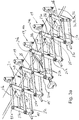
- a plurality of clips 19 are arranged on each of the guide rails 7a to 9b, the clips 19 arranged on a guide rail 7a to 9b being connected to one another via an articulated chain 21, which is also known as "Nürnberger Schere" (lazy Tongs) is known. In this respect, it is sometimes also referred to as a concertina gate.
- This articulated chain 21 is shown in excerpts in an enlarged detailed representation in a spatial representation or top view for a guide rail 7a, 7b or 9a, 9b with reference to FIG Figures 3a and 3b shown.
- This articulated chain 21 (“Nürnberger Schere") consists of several crossed rods or scissor levers 23a and 23b which are more or less arranged in a plane parallel to a guide rail. In this case, two scissor lever arrangements extending in a zigzag shape relative to one another are used to form the aforementioned articulated chain 21.
- Out Figure 3a It can be seen that a first scissor lever arrangement with a zigzag-shaped first scissor lever 23a and a second scissor lever arrangement with a scissor lever 23b which is offset and in opposite directions and which also run in a zigzag shape is provided.
- Two consecutive scissor levers 23a are each positioned in a V-shape to one another, with two successive first scissor levers 23a arranged in a V-shape in plan view being articulated to one another, for example via articulated joints or articulated axles 24a.
- the mentioned second scissor lever arrangement is provided, the scissor levers 23b being arranged correspondingly in a V-shape, two successive scissor levers 23b each via joints further away from the clamps or hinge axes 24'a or hinge axes 24'b closer to the clamps with a respective next one second scissor lever 23b are also articulated.
- Both zigzag-shaped scissor lever arrangements on the one hand with the scissor lever 23a and on the other hand with the scissor lever 23b are then offset from one another in such a way that a first scissor lever 23a intersects with a second scissor lever 23b and at the intersection via a central pivot point or a central axis of rotation 25 are articulated to one another.
- the first scissor levers 23'a and the second scissor levers 23'b interacting therewith are only approximately half the length, so that their common axis of rotation 25'a preferably ends in a guide device 27 and is adjustably guided therein perpendicular to the direction of extent of the guide rail.
- This is shown in the schematic top view Figure 3b to see.
- the ones lying on the outside, which are only half as long Scissor levers are denoted by the reference symbols 23'a and 23'b, respectively.
- the Gelenckette 21 is practically doubled and comprises two joint chains with scissor levers 23a and 23b that are congruently arranged one above the other in plan view, which are arranged at a smaller distance from one another, which, however, is sufficient that the preferably in the direction of the middle Stretching frame protruding articulation points 24b of the scissor levers 23b come to lie above and below the relevant guide rail 7 or 9.
- the aforementioned articulation points 24b provided in the area of the clips 19 are fixedly connected to the clips or clip bodies at these points, so that in the top view according to FIG Figure 3b the axes 24b and the associated clips 19 always remain in the same position with respect to the width of the guide rail, regardless of the spreading movement of the articulated chain 21, that is, they can be displaced with respect to the respective guide rail only according to the dashed line L Figure 3b are.
- the vertical axes of rotation 24a and 24'a which are remote from the clips 19, also include spacers 23c, whereby the upper and lower levels of the scissor levers 23a and 23b are kept at a distance.
- the vertical joint axes 24b and 24'b close to the clip are located in the area of the respective guide rail in plan view, so that here the joint axes are not continuous between the upper and lower levels of the respective scissor lever arrangement, but one for each the upper and the lower level a separate joint 24b and 24'b, congruent in plan view, is provided, between which the respective guide rail runs.
- the joint axes 24b and 24'b close to the clip are each connected to the associated clip bodies.
- the above-mentioned spacers 23c between the upper and lower levels of the scissor levers 23a and 23b are provided with a guide, preferably in the form of a bore, through which an extension section 19 'extends perpendicular to the course of the respective guide rail, this extension section 19 'is firmly connected to a support and carrying structure 49 carrying the clip or clip body 19, which then merges into the extension section 19' leading away from clip body 19, so that when the link chain moves apart or together, the clip bodies in question are underneath the guide rail Generating a larger lateral distance from one another or moved towards one another while reducing their lateral distance to an adjacent clip, while the clip bodies always remain in a perpendicular orientation to the course of the respective guide rail .
- the mentioned guide bodies 23c arranged between the upper and lower levels of the scissor levers 23a and 23b also serve for guidance.
- the clips 19 connected to one another via a scissor lever construction in the manner of an articulated chain 21 are also coupled with adjustment guides in the form of corner connectors 29.
- These corner connectors 29 each have an opening in which the relevant corner connector is guided relatively displaceably on the one hand relative to one guide rail 7a or 7b and on the other hand to the second guide rail 9a, 9b perpendicularly crossing this guide rail in the area of the corner connector 29.
- the adjustment guides / corner connections 29 held on these guide rails are accordingly taken along via these second guide rails 9a, 9b, with an enlargement of the Distance between the two guide rails 9a, 9b, as a result of which the clips sitting on the first guide rails 7a, 7b are now increasingly further removed from one another (also at regular intervals).
- the mentioned articulated chain 21 is pivoted more and more into the open position when the guide rail moves apart, whereby the distances between all adjacent pairs of clips become larger, but always remain the same.
- the two first guide rails 7a, 7b are located on a first rail guide plane, and the second guide rail crossing them perpendicularly 9a, 9b are arranged at least at the level of the material thickness of the guide rail in a second rail guide plane located below or above.
- the clips sitting thereon are, however, usually adjusted so that the clamping plane of all clips 19, regardless of whether they are slidably arranged on the first or second pair of guide rails 7a, 7b or 9a, 9b, form a common clamping plane E.
- the clamping plane E of the clips 19 is also the travel plane of the clips 19, in other words, the plane E is the plane in which all guide rails 7a, 7b and 9a, 9b are ultimately arranged or essentially are arranged.
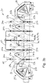
- the adjustment of the two first and the two second guide rails can be carried out by suitable drive devices, as in principle on the basis of the Figures 4a to 4c is explained schematically.
- a first deflecting shaft 33a is driven via a first drive motor 31 and a gear 31a downstream of this drive motor 31 and a rotating first transmission device 32.
- This first deflecting shaft 33a stands in via a further revolving second transmission device 34 Connection to a second deflecting shaft or deflecting wheel 33b arranged offset thereto and running parallel to the first deflecting shaft 33a.
- the opposite deflecting arrangement for the transmission device 34 does not have to be designed as a continuous deflecting shaft, but it can, as in FIG Figure 4a a reversing wheel 33b rotating about a wheel axis is also shown opposite each other.
- the transmission device 34 itself can basically be designed in the manner of a chain, belt, belt, spindles, etc. Chains are preferred due to the specific conditions of use.
- the two transmission shafts 33a, 33b are arranged parallel to one another at such a large distance that sufficient space is provided for the aforementioned guide rails 7a, 7b to reach a maximum stretching position.
- One guide rail 7a is fastened to the lower run 34a and the other guide rail 7b of the so-called first guide rails 7a, 7b is fastened to the upper run 34b of the second transmission device 34, for example in each case via a driver 28 (see Fig. Figure 4c ).
- a transmission device 32 driven in the direction of rotation by the drive motor 31, depending on the direction of rotation, the two first guide rails 7a, 7b move away from each other according to the double arrow representation 13 or, if the direction of rotation of the motor (or a downstream gear) is reversed, towards each other within the stretching frame 5 can be proceeded.
- the variant according to Figure 4a for example as adjustment in the transverse direction, that is to say, in the so-called transverse direction or TD direction, they are abbreviated.
- a second and a third drive device is provided for the two further second guide rails 9a and 9b, for example adjustable in the machine longitudinal direction (MD), around the two guide rails 9a and 9b separated and not only towards each other and away from each other but to be able to adjust both for example in the same direction to one side of the stretching frame.
- MD machine longitudinal direction
- Figure 4b first the drive and adjustment device for one of the two further guide rails is shown and described, namely, for example, the guide rail 9a.
- one or more stages starting from a second drive motor 37 with the gear 37a downstream of this drive motor 37, are also one or more stages several transmission devices 38 optionally provided with one or more intermediate shafts or intermediate gears which can be set in rotation.
- two remote second transmission shafts 39a, 39b are provided, running parallel to one another and perpendicular to the two first transmission shafts 33a, 33b, which are in drive connection with one another via a further circumferential transmission device 40.
- the transmission device 40 can preferably consist of a chain, belt or belt of a spindle or the like.
- the two transmission devices 40 for example consisting of a revolving chain, are arranged at a lateral distance from one another adjacent to the edge of the stretching frame and are driven from the drive motor 31 via the continuous shaft 39a.
- a second transmission shaft instead of a second transmission shaft, only two deflection wheels 39b can be provided here as well, as shown on the basis of FIG Figure 4b is shown.
- one of the two second guide rails 9a, 9b is fastened either to the lower run 40a or to the upper run 40b of the revolving transmission device 40, preferably again via a respective driver 42, so that when the drive motor 37 rotates, the first guide rail 9a of the two second guide rails 9a, 9b either in the direction of the center 17 or away from this center to the edge of the stretching frame, in accordance with the double arrow representation 15.
- This adjustment direction can then also be defined, for example, as an adjustment in the machine direction MD.
- a second drive device 137 in the form of a motor possibly with a downstream gear 137a or a downstream transmission device 138, is provided, via which in turn a first transmission shaft 139a can be set in rotation, depending on the direction of motor rotation in one or in an opposite direction Direction.
- a revolving transmission device 140 is again provided, which can also consist of a chain, a belt, a belt, a spindle or the like.
- the corresponding transmission device 140 When the transmission shaft 139a rotates, the corresponding transmission device 140 is driven to rotate in one direction or in the opposite direction, this rotating transmission device 140 rotating at the opposite end to the transmission shaft 139a via a second shaft provided there or only separately mounted drive wheels 139b provided there .
- the corresponding guide rail 9b is attached via a driver 142 either to the upper or lower run of the revolving transmission device 140, so that ultimately when the third motor and drive device 137 is driven, it depends on the direction of rotation and thus on the direction of rotation of the transmission shaft 139a and both subsequent transmission devices 140, the guide rails 9b can be moved either in the direction of the center of the stretching frame or away from the center of the stretching frame in the stretching frame according to the double arrow representation 15.
- the guide rail 9b can be adjusted independently of the guide rail 9a by the third drive unit 137.
- the second and third drive devices 37, 137 can be adjusted such that, for example, the two guide rails 9a, 9b, which run parallel to one another can be adjusted towards one another, reducing the distance to one another, or can be moved further away from one another, similar to the two guide rails 7a, 7b. Due to the separate drive devices for the two guide rails 9a, 9b, however, there is also the possibility that, for example, both parallel guide rails 9a, 9b can be adjusted in the same direction, not only while maintaining their distance from one another, but also by reducing their distance from one another, which will be discussed below.
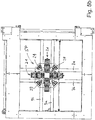
- the two first and the two second guide rails 7a, 7b and 9a, 9b could then be moved by the motor drives 31, 37 and 137 described accordingly into a position further away from one another, whereby the corresponding adjustment guides / corner connections 29 are moved outwards with respect to the respectively perpendicular section of the guide rails and the clips located in between are increasingly adjusted into positions spaced apart from one another by the articulated chains 21, as shown schematically with reference to FIG Figure 5c is shown.
- the position in which the stretching process is ended is also referred to below as the end position EP.
- the actual stretching process takes place between the start position and the end position, even if an after-treatment (annealing) can be carried out after the end position, in which the film is subjected to a certain relaxation, for example, and the distance between the opposing clips and thus the Distance between the pairs of opposite guide rails is again slightly reduced.
- the final position that can be reached via this is also referred to as the post-treatment position.
- the actual stretching process is carried out - as will be discussed later - with appropriate heat treatment in one or more of the ovens provided.
- both second guide rails 9a and 9b are preferably separately driven by two separate motors 37, 137, to be precise for example likewise via a separate rotating transmission device 40 or 140.
- the guide rails also referred to as longitudinal guide rails or short MD guide rails 9a, 9b
- the guide rails can be adjusted further forwards in the entire system and positioned there in order to then be fitted with one in this position as explained to make stretching plastic material section 41.
- the common adjustment in one direction is implemented for both guide rails 9a, 9b with the aid of two individually controllable motors 37 and 137.
- the drive trains can be designed as identically as possible.
- the two motor gears 37a and 137a and the associated drive trains 37 and 137 can only be designed for half the force or power required, since they only have to adjust one guide rail via which the corresponding stretching forces are applied to the plastic material sections to be stretched have to.
- the further provided drive train for the two perpendicular guide rails 7a and 7b which can only be moved together towards each other or away from each other during the stretching process, require a more powerful motor than conventional drive devices, which is designed to drive the two Can generate guide rails acting in opposite directions of stretching forces. Instead of this, or in part in addition to a more powerful motor, a transmission with a different gear ratio can be selected.
- the clips 19 can be positioned as close as possible to an edge section of the stretching frame 5 in a position that is moved towards one another, so that a corresponding adjustment movement of the two other guide rails 9a, 9b in a common direction is not necessary (although this is provided can be).
- the assembly field 45 or the film section 41 to be placed therein is in the assembly position BP before implementation of the stretching process assumes a position in a plan view of the stretching system and / or covers an area that is free of overlap to the surface of the film section 41 in the start position SP or only overlaps in a partial area that is less than 80%, in particular less than 70%, 60 %, 50%, 40%, 30%, 20% or less than 10% of the area of a plastic material section 41 to be stretched before the stretching process is carried out.
- Whether and how extensively a plastic material section to be stretched would overlap with the same plastic material section in its loading position BP when this plastic material section has been moved from its loading position BP to its starting position SP also depends on the size of the film pattern, i.e. on the size of the plastic material section from.
- Corresponding sections of plastic material can vary, for example, from 2 cm x 2 cm to, for example, 20 cm x 20 cm.
- the relevant pattern of a plastic material section that is to be stretched can have edge lengths that, for example, have a minimum edge length of 2 cm, 3 cm, 4 cm, 5 cm, 6 cm, 7 cm, 8 cm, 9 cm, 10 cm, 11 cm, 12 cm, 13 cm, 14 cm, 15 cm, 16 cm, 17 cm, 18 cm or 19 cm or vice versa have a maximum edge length of 2 cm, 3 cm, 4 cm, 5 cm, 6 cm, 7 cm, 8 cm, 9 cm, 10 cm, 11 cm, 12 cm, 13 cm, 14 cm, 15 cm, 16 cm, 17 cm, 18 cm or 19 cm or 20 cm.
- each guide rail 7a to 9b If an odd number of clips is used on each guide rail 7a to 9b, it remains on each Guide rail in the middle seated clip 19, 19a in the longitudinal direction of the respective guide rail largely immovable ( Figure 3a , 3b and 5c ), although it is basically arranged to be slidable on the respective guide rail. This is because the respective guide rails move symmetrically away from one another in pairs during the stretching process, so that the respective middle clip 19a on the guide rail largely maintains its position in such a way that it is aligned with the center 17.
- the maximum mechanical load can be, for example, 2000 N / axle, that is, per guide rail. This means that either 400 N / clip (with five clips) or 285 N / clip (with seven clips) load must be absorbed.
- the maximum stretching ratio can be, for example, 1: 10.4 and the stretching speed, for example be continuously adjustable between 1 - 500 mm / sec. But these values can also vary accordingly.
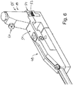
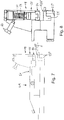
- FIG. 6 Based on Figure 6 is once in a slightly perspective side view and in Figure 7 In an exact side view, a clip 19 with associated support and load-bearing structure 49 is shown in a schematic structure, here for example with an additionally provided force measuring device 51.
- this force measuring device 51 is not absolutely necessary, which means that clips with and without force measuring device 51 on the guide rails can give.
- the clip device itself usually comprises a clip body or generally a clip 19 with a first clamping jaw 53, which is generally located below, the contact surface of which faces upwards, and a second upper clamping jaw 54, the contact and contact surface of which faces downwards.
- This second or upper clamping jaw 54 is preferably exchangeably fastened to the underside of the clip clamping device 55, so that the second or upper clamping jaw 54 can be moved (and / or pivoted) in the direction of the lower clamping jaw 53 in order to move the corresponding edge in the clamping position to hold and clamp a section of material to be stretched.
- the respective clip clamping device 55 is acted upon by force by a spring force device 57 in the open position, so that if it does not a counterforce, the edge of the plastic material section to be stretched is released.
- a corresponding piston chamber 59 is pressurized with a pressure medium, the pressure of the pressure medium being so great that the clip clamping device 55 is moved from its raised release position into its lowered clamping position against the force of the spring device 57 mentioned. If the piston chamber is ventilated again or relieved of pressure, the aforementioned spring force device 57 raises the clip clamping device back into the release position.
- the corresponding line connection 60 to a pressure medium line for pressurizing the piston chamber 59 is shown in FIG Figure 8 drawn. Basically provided pressure lines or compressed air or nitrogen lines lead to all clip bodies, for example to the in Figure 8 Line connection 60 shown. Pressure lines 63 are not shown in FIGS. 6, 7 and 8, but they are shown, for example, in FIG. 3b.
- the clip carrying device 49 is connected to the actual clip arrangement (that is to say with the lower or first clamping jaw 53, with the clip) via the section that receives the force measuring device 51 the clip clamping device 55 and the attached upper or second clamping jaw 54).
- the force measuring device 51 can also include or be formed from a bending measuring strip BMS, a strain gauge or, for example, an optical waveguide LWL. There are no restrictions on certain measuring systems. In other words, all suitable measuring systems can be used.
- the alignment of the aforementioned force measuring device 51 is preferably arranged parallel or at an angle that is less than 90 °, in particular less than 80 °, 75 °, 70 °, 65 °, 60 ° °, 55 °, 50 °, 45 °, 40 °, 35 °, 30 °, 25 °, 20 °, 15 °, 10 ° and less than 5 ° in relation to plane E ( Fig. 7 ) of the film section to be stretched, that is, preferably more or less parallel or essentially parallel to the plane E of the film section to be stretched, whereby relatively accurate measured values can be determined. From the page representation according to Figure 8 It can be seen here that a lower section of the support and carrying device 49 for the clip 19 is separated by a gap, so that the entire support for achieving a high level of measurement accuracy takes place only via the force measuring device 51.
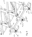
- Figure 9 shows a three-dimensional representation of a section of a guide rail 7a, 7b or 9a, 9b with a remaining small section of the articulated chain 21 and above all the clips positioned on the guide rails.
- the clip 19a which is preferably arranged in the middle, differs in terms of its support and bearing structure 49 from the support and bearing structure 49 of the other clips and clip bodies 19, because the aforementioned force measuring device is preferably only provided in the area of the middle clip 19a or is formed, and the clip bodies 19 provided laterally offset from the center with respect to a guide rail 7a, 7b or 9a, 9b, no further force measuring devices are necessary.
- the aforementioned force measuring device can of course also be provided as an alternative or in addition, regardless of its design and type, in several and / or in other positions or in other clips. Furthermore, it would also be conceivable that, for example, only one or, for example, only two clips with a corresponding force measuring device are provided in the overall system.
- a corresponding clamping jaw 54 for attachment to the underside of a clip clamping device 55 is provided with a groove-shaped recess 81 which has an undercut 83 on the two opposite longitudinal sides, into which a corresponding section of the underside of the clip clamping device 55 can engage.
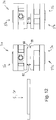
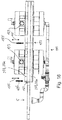
- grooves 77 which run parallel to one another or intersect at a distance, which can be V-shaped in cross-section, for example ( Figure 10c ). It is also possible to form a large number of clamping ribs 79 which run parallel to one another, preferably parallel to the corresponding film edge of the film section to be clamped ( Figure 10d ).
- the groove-shaped recess 81 can also be seen, which is provided with lateral undercuts 83 as shown here, for example, so that it can be interchangeably plugged onto this clip clamping device 55 when the underside of the clip clamping device 55 has a correspondingly complementary shape.
- a free adjustment path for the clip clamping device 55 is provided within the clip body 19, which is designed in the shape of a cylinder, whereby this cylinder can be adjusted in the cavity in a clip body 19 along an adjustment path, with the aforementioned pressure medium against the spring device 57
- the clip body with the mentioned clip clamping device 55 is thus designed to be piston-shaped or piston-like, with the corresponding clamping jaws being exchangeably attached to the underside of the adjusting cylinder (piston). It is of course also possible that other geometries can be used to assemble the mentioned clip contact sections, in particular to attach or attach etc ..
- An easily exchangeable connection of the exchangeable clip contact sections is preferably provided, which can then be exchanged and installed depending on the intended use.
- the different clip contact sections 65 can be selected in each case, which enable an optimal fixation on the clip table with respect to the plastic material to be stretched.
- the exemplary configurations of the different clip contact sections shown can be used, depending on which plastic material is to be stretched, for example a plate-shaped plastic material or a foil, film or membrane-shaped or similar material or, for example, a fabric material.
- the clamping side 85 which as a rule points upwards, can have a clamping surface 87 on the upper side of the lower clamping jaws 53, which can be designed accordingly, that is, for example, can again have a large number of upwardly protruding teeth or ribs 89 ( Figure 11a ) or a multiplicity of grooves or grooves 191 (V-shaped in cross section) running in parallel to one another ( Figure 11b ). These can preferably run parallel to the clamping edge of the film section to be clamped, or else offset by 90 °. Furthermore, it is conceivable that the V-shaped grooves or grooves 191 represent a grid pattern. This is in Figure 11b shown. It is also possible to use a large number of clamping grooves 179, likewise again preferably parallel to the edge of the film, as shown in FIG Figure 11c is shown.
- Figure 11d shows a variant with a rubberized clamping surface 87 or upper clamping side 85.
- the mentioned lower clamping jaws 53 are preferably designed in the form of exchangeable cleat table attachment elements 53 '. This has the advantage that these clamp table add-on elements 53 'can be interchangeably mounted on a clamp table substructure 53 "in order to be able to optimally adapt to the film sections to be stretched in order to achieve particularly good clamping engagement Figure 9 to see where the Figures 11a to 11d
- FIG. 12 Based on Figure 12 a furnace construction or furnace arrangement is shown in a schematic representation in order to achieve particularly good stretching results.
- the representation according to Figure 12 shows a first and a second furnace arrangement 3a and 3b, each with a furnace 3'a or 3'b provided above the stretching frame and a further furnace 3'b or 3'b provided below the plane of the stretching frame.
- Sufficient vertical clearance 93 is provided between the bottom 97 of the upper ovens and the top 99 of the lower ovens, which is sufficient for the stretching frame 5 to rest on the guide rails, the clips sitting on them, the pressure lines and all attachments between the respective upper and lower Ovens can be moved.
- Figure 12 the arrangement is shown in which the stretching frame 5 is still outside the ovens in its starting position SP (or loading / unloading position). It can also be seen from the illustration that in each case the upper furnace is arranged more or less congruently with a lower furnace.
- a corresponding temperature control of the film section to be stretched can usually be achieved be made.
- the temperature control is preferably not carried out by infrared radiation (which would mean that the film section to be stretched can only be heated accordingly after it has been moved into the oven), but by supplying heated air, which is already applied to the film section to be stretched before the stretching frame is inserted appropriate temperature has been brought.
- Figure 12 Based on Figure 13 a corresponding representation is to be made Figure 12 in which the stretching frame 5 with a material section 41 to be stretched is already located in the first oven arrangement 3a between the first upper and lower ovens 3'a, 3 ". In this position, the stretching process would normally start from the start position SP to the end position EP are carried out.
- FIG Figure 14 it can be seen that at least on one side of a furnace (e.g. in the furnace 3'a or 3'b) a fan or a fan wheel 195 can also be arranged within a furnace chamber, which is preferably directly driven by an external motor 173, in which the fan shaft is directly coupled to the motor shaft or sits directly on the motor shaft.
- a direct drive formed in this way is therefore preferably implemented.
- An opening 175 provides for the air supply. This can be done not only in the upper ovens 3'a, 3'b etc. but alternatively or can also be installed in the respective lower ovens 3 "a, 3" b etc.
- a passive air supply can also be provided, but this is less advantageous than an active air supply in accordance with the direct drive explained above.
- an active or a passive air supply for the furnace can be attached to the opening mentioned.
- the stove requires an additional air supply, as it circulates the air that is present in the air circulation mode.
- Figure 14a a lower direct view, for example, of a first furnace, that is to say for example a first upper furnace 3'a (or a plan view of a lower furnace 3 "a) and Figure 14b a corresponding bottom view of a second or third furnace, for example a furnace 3'b or a plan view of the associated lower furnace 3 "b reproduces, as it can be used, for example, for the annealing area.
- Figure 14a a lower direct view, for example, of a first furnace, that is to say for example a first upper furnace 3'a (or a plan view of a lower furnace 3 "a)
- Figure 14b a corresponding bottom view of a second or third furnace, for example a furnace 3'b or a plan view of the associated lower furnace 3 "b reproduces, as it can be used, for example, for the annealing area.
- a central exhaust opening 301 in a base cover 303 is a focused exhaust, for example of air, can be carried out on the plastic material section 41 to be stretched located in the stretching frame underneath, with the opening, dimensioning and arrangement of the exhaust opening 301 depending on the size and position of the to stretching plastic material section is matched.
- the blowout opening 301 is at least approximately in plan view congruent with the plastic material section that has not yet been stretched.
- suction openings 305 are formed in the embodiment shown in the form of angular suction openings 305 ', each with a certain leg length run from the respective corner area, and decrease in their broad extent from the corner area to the end of the line.
- the length of each leg of the angular suction opening 305 ' is less than half the length of the stretching frame, so that in each case a material section 307 remains which separates the ends of the angularly arranged suction leg opening 305 ".
- blow-out opening 301 is provided, but this is now opposite the blow-out opening 301 in the view according to FIG Figure 14a Is dimensioned many times larger, namely preferably in adaptation and coordination to the size and thus the longitudinal and transverse extension of the stretched plastic material section.
- the outer angular suction openings 305 are provided, with the suction leg openings 305 ′′ running at an angle to one another.
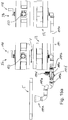
- FIGS 15a and 15b show once in a schematic side view and once in a spatial representation the two successive furnace arrangements 3a and 3b already described, one furnace with a passive air supply 198 being provided for each of the two upper furnaces above the travel path V for the stretching frame (and preferably with the fans mentioned 195).
- additional, also active cooling for the upper ovens 3'a and 3'b can take place via the openings 198 (which can optionally be provided with additional chimneys) either manually or, for example, automatically (that is, automatically controlled), such as this, for example, already in Figure 14 with respect to opening 175 on the top of a preferably upper oven.
- the ovens 3 "a and 3" b arranged below the travel path V can be supplied with air via an active air supply 199, for example using air pipes and air pipe systems 199a, which are also equipped with a flap control 199b and / or a fan 199c, for example can, for example Sucks in air via a motor 199d via a suction opening 199f (suction nozzle 199f) and supplies it to the interiors of the ovens in question via the pipe system.
- an active air supply 199 for example using air pipes and air pipe systems 199a, which are also equipped with a flap control 199b and / or a fan 199c, for example can, for example Sucks in air via a motor 199d via a suction opening 199f (suction nozzle 199f) and supplies it to the interiors of the ovens in question via the pipe system.
- a blow-out device is also designated with the reference number 199e, which is funnel-shaped in the embodiment shown (but can also be designed completely differently), whereby a cool medium, usually air, can be fed to the clips via this opening 199e in order to thereby cool the clips cause.
- a cool medium usually air
- the lower ovens 3 "a and 3" b can be designed with a passive air supply, for example using the fans mentioned, whereas the upper ovens 3'a, 3'b etc. based on Figure 15a and 15b active air supply shown.
- an upper and a lower oven 3'a, 3 "a etc. with a passive air supply, for example using the fans mentioned or both an upper and a lower oven 3'a, 3" a etc. can be provided with an active air supply.
- manually or automatically adjustable chimneys see Figure 15a ) as shown on the upper ovens 3'a and 3'b, respectively. Alternatively, these can also supply additional air with active cooling.
- the insulation 277 explained above and in particular in the form of the mentioned insulation plates 277a have a corresponding recess where the ovens are arranged above or below the respective insulation plate, so that the clips and the guide rails and, above all, the material section to be stretched are open in the respective furnace comes to rest, and the heating can be carried out optimally.
- the mentioned insulation is used to separate the hot air area for stretching from the rest of the machine, creating a space between the upper and lower oven.
- FIG 17 the explained insulation 277 with the insulating plates 277a is shown separately in a perspective view, that is to say without the upper and lower ovens.
- These insulations 277 then have corresponding central openings 279a with respect to the respective one upper furnace 3'a or for example 3'b facing insulating plate 277 ', as well as a corresponding lower opening or recess 279b facing the respective lower insulating plate 277 ", on which the lower furnaces 3" a, 3 "b etc . are positioned.
- a first oven 3a in each case preferably serves as a heating and stretching oven in order to bring the film section to be stretched to the optimum temperature before and / or during the stretching process.
- the stretching frame can then be moved into a subsequent further oven, which is used, for example, as a post-treatment oven, in which the clips are moved towards one another at least to a minimum in order to be able to subject the film section to a certain relaxation.
- a post-treatment oven in which the clips are moved towards one another at least to a minimum in order to be able to subject the film section to a certain relaxation.
- Such ovens can also be referred to as an annealing zone.
- a further oven 3c or a further oven arrangement 3c can be provided after the second oven, which is designed, for example, as an additional stretching zone, which functions, for example, as a cooling zone and / or as a further annealing zone, in which the film is applied to a specific Temperature is cooled (ovens 3a, 3b, and 3c in Figure 1b ).
- the different ovens can be operated at different temperatures.
- the upper ovens can have temperatures that differ from the temperatures in the lower ovens. There are also no restrictions in this regard.
- the through-openings to an adjacent oven can be almost completely closed between the individual ovens or oven zones by means of shutter panels.
- the stretching frame in its overall structure and the film sections to be stretched held therein can be moved between an upper and a lower oven, the side sections being sealed parallel to the direction of travel V by insulation or insulating plates, and the front and back sections in the direction of travel V trailing opening areas for inserting and moving the stretching frame into the oven or out of the oven through shutter screens, preferably as far as possible, ie preferably predominantly or almost completely closed off in order to be able to carry out an efficient heat treatment.
- the ovens are preferably designed in such a way that the associated shutter screens, in the closed position, open the oven for extending and retracting the stretching frame by at least 90%, in particular at least 91%, 92%, 93%, 94%, 95%, 96 %, 97%, 98% or at least 99% occluded.
- each oven 3a, 3b, 3c is designed in such a way that it is at a temperature of 300 ° C. +/- less than 50 ° C., in particular less than 40 ° C, 30 ° C, 20 ° C or 10 ° C and at least one other furnace and / or a furnace with a temperature of 400 ° C +/- less than 50 ° C, in particular less than 40 ° C, 30 ° C, 20 ° C or 10 ° C is heated and / or a third furnace 3c is provided in particular for a second annealing phase and / or a temperature reduction or cooling.
- the ovens can be heated up using electric heaters in recirculation mode, for example. For more precise temperature control, readjustments can be made, for example, with the aid of a manually adjustable air slide. If cooling is required for an oven, especially for a last oven, active cooling is preferably installed for this purpose, with a fan being able to blow active air into the stretching space.
Landscapes
- Engineering & Computer Science (AREA)
- Mechanical Engineering (AREA)
- General Health & Medical Sciences (AREA)
- Chemical & Material Sciences (AREA)
- Analytical Chemistry (AREA)
- Biochemistry (AREA)
- Physics & Mathematics (AREA)
- General Physics & Mathematics (AREA)
- Immunology (AREA)
- Pathology (AREA)
- Life Sciences & Earth Sciences (AREA)
- Health & Medical Sciences (AREA)
- Shaping By String And By Release Of Stress In Plastics And The Like (AREA)
Claims (13)
- Dispositif d'étirage monoaxial ou biaxial de sections en matière plastique (41) au moyen d'un châssis d'étirage (5) présentant les particularités suivantes :- il est prévu deux premiers rails de guidage (7a, 7b) s'étendant parallèlement à distance l'un de l'autre et mobiles en sens perpendiculaire,- il est prévu deux deuxièmes rails de guidage (9a, 9b) s'étendant parallèlement à distance l'un de l'autre et mobiles en sens perpendiculaire,- les premiers rails de guidage (7a, 7b) sont orientés perpendiculairement aux deuxièmes rails de guidage (9a, 9b) et disposés de telle sorte que les quatre rails de guidage (7a, 7b ; 9a, 9b) pris conjointement forment, en vue de dessus, un rectangle ou un carré ou approchent d'une forme rectangulaire ou d'un carré,- au moins deux pinces (19) sont disposées respectivement sur les deux premiers et sur les deux deuxièmes rails de guidage (7a, 7b ; 9a, 9b), permettant de serrer une section de feuille (41) à étirer pour mettre en œuvre une opération d'étirage,- les deux premiers et les deux deuxièmes rails de guidage respectifs (7a, 7b ; 9a, 9b) peuvent être déplacés entre une position initiale (SP) dans laquelle ils sont rapprochés l'un de l'autre, et une position finale (EP) dans laquelle ils peuvent être éloignés l'un de l'autre, de telle sorte qu'une section de feuille (41) préalablement insérée et fixée est étirée de manière monoaxiale ou biaxiale,
caractérisé en ce que- la zone de déplacement (V) pour le châssis d'étirage (5) à l'intérieur de l'un ou des plusieurs fours (3a, 3b, 3c) est isolée vers le haut et vers le bas par une isolation (277), laquelle isolation (277) présente une zone d'ouverture (279a, 279b) sur la face inférieure (97) des fours supérieurs (3'a, 3'b) et sur la face supérieure (99) des fours inférieurs (3"a, 3"b),- étant entendu quea) plusieurs fours (3a, 3b) sont disposés les uns derrière les autres, la section de feuille (41) à étirer pouvant être soumise à un étirage dans un premier four (3a) et une phase de post-traitement pouvant être mise en œuvre pour la section de feuille (41) étirée dans au moins un four suivant (3b), à savoir à la manière d'une zone de recuit et/ou d'une zone de relaxation dans laquelle éventuellement la distance entre les rails de guidage (7a, 7b ; 9a, 9b) et donc entre les pinces (19) disposées en vis-à-vis est réduite légèrement au moins par rapport à la distance existant lorsque la position finale (EP) est atteinte à la fin de l'opération d'étirage maximal, et/oub) le dispositif comprend deux ou au moins deux fours (3a, 3b) ou trois ou au moins trois fours (3a, 3b, 3c), un four respectif (3'a, 3'b) étant prévu au-dessus de la trajectoire de déplacement du châssis d'étirage (5) et un four respectif (3"a, 3"b) étant prévu au-dessous de la trajectoire de déplacement, et/ouc) un four respectif (3a, 3b, 3c) est réalisé de manière à être chauffé à une température de 300 °C, à moins de 50 °C près, notamment à moins de 40 °C, 30 °C, 20 °C ou 10 °C près et/ou au moins un four ou un autre four est chauffé à une température de 400 °C, à moins de 50 °C près, notamment à moins de 40 °C, 30 °C, 20 °C ou 10 °C près et/ou un troisième four (3c) est prévu pour une deuxième phase de recuit et/ou pour un abaissement ou refroidissement de la température. - Dispositif selon la revendication 1, caractérisé en ce que l'isolation (277) est disposée dans la hauteur de la face inférieure (97) des fours supérieurs (3'a, 3'b) et de la face supérieure (99) des fours inférieurs (3"a, 3"b).
- Dispositif selon la revendication 1 ou 2, caractérisé en ce qu'un obturateur est respectivement prévu sur le côté entrée et/ou sur le côté sortie d'un ensemble à fours (3a, 3b), lequel obturateur est déplaçable en position d'ouverture pour faire entrer ou sortir le châssis d'étirage et est déplaçable en position de fermeture pour réaliser une étape de traitement dans l'ensemble à fours, dans laquelle position de fermeture l'obturateur obture de préférence l'ouverture concernée sur au moins 91 %, 92 %, 93 %, 94 %, 95 %, 96 %, 97 %, 98 %, ou sur au moins 99 %.
- Dispositif selon l'une des revendications 1 à 3, caractérisé en ce qu'il est prévu au moins un four (3a, 3b), étant entendu quea) le four supérieur (3'a, 3'b) et le four inférieur (3"a, 3"b) associé sont dotés d'une alimentation en air passive (198), oub) le four supérieur (3'a, 3'b) et le four inférieur (3"a, 3"b) associé sont dotés d'une alimentation en air active (199), ouc) soit le four supérieur (3'a, 3'b) soit le four inférieur (3"a, 3"b) est doté d'une alimentation en air passive (198) et le four opposé respectif (3"a, 3"b) est doté d'une alimentation en air active (199), ou inversement.
- Dispositif selon l'une des revendications 1 à 4, caractérisé par les particularités supplémentaires suivantes :- le dispositif est conçu de telle sorte qu'outre la position initiale (SP) au début d'une opération d'étirage et la position finale (EP) après la réalisation d'une opération d'étirage, les rails de guidage (7a, 7b; 9a, 9b) et donc les pinces (19) reposant sur ceux-ci peuvent également être déplacés en une position de chargement (BP), et- la position de chargement (BP) est située de manière à se trouver asymétriquement à l'intérieur du châssis d'étirage (5) et donc à être plus proche d'au moins un côté long du châssis d'étirage (5) que du côté opposé du châssis d'étirage.
- Dispositif selon la revendication 5, caractérisé en ce que le dispositif est conçu de telle sorte qu'au moins les deux premiers rails de guidage (7a, 7b) ou au moins les deux deuxièmes rails de guidage (9a, 9b) sont non seulement déplaçables en éloignement ou en rapprochement l'un de l'autre pour le déplacement entre leur position initiale (SP) et leur position finale (EP), mais peuvent également être déplacés dans un même sens pour passer à une position de chargement (BP).
- Dispositif selon la revendication 5 ou 6, caractérisé en ce qu'au moins les deux rails de guidage (9a, 9b), qui sont non seulement déplaçables en rapprochement ou en éloignement l'un de l'autre, mais aussi dans le même sens de déplacement, peuvent être entraînés et déplacés par des moyens d'entraînement et de transmission de force (37, 38, 39a, 39b, 40 ; 137, 138, 139a, 139b, 140) séparés.
- Dispositif selon la revendication 7, caractérisé en ce que les deux rails de guidage (7a, 7b), qui ne sont déplaçables que conjointement en rapprochement ou en éloignement l'un de l'autre, sont entraînés et déplaçables conjointement par un moteur d'entraînement (31) et, à cet effet, les deux rails de guidage (7a, 7b) sont couplés par un moyen de transmission de force (34) commun en recirculation, l'un (7a) des rails de guidage étant ancré de manière embarquée sur le brin inférieur (34a) et l'autre rail de guidage respectif (7b) sur le brin supérieur (34b), de préférence par un entraîneur (28).
- Dispositif selon l'une des revendications 5 à 8, caractérisé en ce que la position initiale (SP) au début de l'opération d'étirage est située au milieu ou aussi près du centre (17) du châssis d'étirage (5) qu'il soit possible de mettre œuvre symétriquement l'opération d'étirage, en particulier l'opération d'étirage biaxial, étant entendu que les rails de guidage (7a, 7b ; 9a, 9b) susceptibles de se déplacer en éloignement l'un de l'autre pendant l'opération d'étirage s'éloignent de la position initiale (SP) selon une mesure identique.
- Dispositif selon l'une des revendications 5 à 9, caractérisé en ce que le champ de chargement (45) ou la section de feuille (41) à placer dans celui-ci, dans la position de chargement (BP) avant la mise en œuvre du procédé d'étirage, selon une vue de dessus de l'installation d'étirage, prend une position et/ou recouvre une surface qui est sans chevauchement avec la surface de la section de feuille (41) dans la position initiale (SP) ou avec un chevauchement d'une zone partielle qui est uniquement inférieure à 80 %, notamment inférieure à 70%, 60%, 50%, 40%, 30%, 20% ou inférieure à 10% de la surface d'une section en matière plastique (41) à étirer, avant la réalisation de l'opération d'étirage.
- Dispositif selon l'une des revendications 5 à 10, caractérisé par les particularités suivantes :- les pinces (19) maintenues de façon déplaçable sur les rails de guidage (7a, 7b ; 9a, 9b) sont retenues par une construction de support (49),- un moyen de mesure de force (51) est prévu entre la construction de support (49) et la pince (19) et/ou sur la construction de support (49), la pince (19) étant retenue par la construction de support (49), et- le moyen de mesure de force (51) comprend de préférence un moyen de mesure de flexion ou une jauge de flexion ou une jauge d'allongement ou un guide d'ondes lumineuses.
- Dispositif selon la revendication 11, caractérisé en ce que le moyen de mesure de force (51) s'étend parallèlement au plan de déplacement (E) des rails de guidage (7a, 7b; 9a, 9b) et/ou parallèlement au plan de serrage (E) dans lequel peut être serrée une section de feuille (41) à étirer, ou bien diffère dudit plan de déplacement et/ou de serrage d'un angle inférieur à 45°, en particulier inférieur à 40°, 35°, 30°, 25°, 20°, 15°, 10° ou inférieur à 5°.
- Dispositif selon l'une des revendications 5 à 12, caractérisé par les particularités suivantes :- le dispositif comprend une zone de chargement et/ou de prélèvement (1) dans laquelle le châssis d'étirage (5) est positionné au moins lorsque les rails de guidage (7a, 7b; 9a, 9b) se trouvent dans la position de chargement et/ou de prélèvement (BP ; EP),- au moins un ensemble à fours (3a) est prévu à côté de la zone de chargement et/ou de prélèvement (1), et- l'ensemble à fours (3a) comprend un four supérieur (3'a) et un four inférieur (3"a), un espace (93) étant ménagé entre la face inférieure du four supérieur (3'a) et la face supérieure du four inférieur (3"a) et étant suffisamment grand pour que le châssis d'étirage (5) soit déplaçable jusque dans le four (3a, 3b) dans ledit espace.
Applications Claiming Priority (2)
| Application Number | Priority Date | Filing Date | Title |
|---|---|---|---|
| DE102018101455.4A DE102018101455A1 (de) | 2018-01-23 | 2018-01-23 | Vorrichtung zum mono- oder biaxialen Recken von Kunststoffmaterialabschnitten |
| EP19152217.6A EP3513945B1 (fr) | 2018-01-23 | 2019-01-17 | Dispositif d'étirage mono ou biaxiale des sections de matière plastique |
Related Parent Applications (1)
| Application Number | Title | Priority Date | Filing Date |
|---|---|---|---|
| EP19152217.6A Division EP3513945B1 (fr) | 2018-01-23 | 2019-01-17 | Dispositif d'étirage mono ou biaxiale des sections de matière plastique |
Publications (3)
| Publication Number | Publication Date |
|---|---|
| EP3674060A2 EP3674060A2 (fr) | 2020-07-01 |
| EP3674060A3 EP3674060A3 (fr) | 2020-09-16 |
| EP3674060B1 true EP3674060B1 (fr) | 2021-05-05 |
Family
ID=65036634
Family Applications (2)
| Application Number | Title | Priority Date | Filing Date |
|---|---|---|---|
| EP19152217.6A Active EP3513945B1 (fr) | 2018-01-23 | 2019-01-17 | Dispositif d'étirage mono ou biaxiale des sections de matière plastique |
| EP20158403.4A Active EP3674060B1 (fr) | 2018-01-23 | 2019-01-17 | Dispositif d'étirage mono ou biaxial des sections en matière plastique |
Family Applications Before (1)
| Application Number | Title | Priority Date | Filing Date |
|---|---|---|---|
| EP19152217.6A Active EP3513945B1 (fr) | 2018-01-23 | 2019-01-17 | Dispositif d'étirage mono ou biaxiale des sections de matière plastique |
Country Status (6)
| Country | Link |
|---|---|
| US (1) | US11097463B2 (fr) |
| EP (2) | EP3513945B1 (fr) |
| JP (1) | JP7302975B2 (fr) |
| KR (1) | KR102265328B1 (fr) |
| CN (1) | CN110065222B (fr) |
| DE (1) | DE102018101455A1 (fr) |
Families Citing this family (25)
| Publication number | Priority date | Publication date | Assignee | Title |
|---|---|---|---|---|
| MX2018003299A (es) * | 2015-09-17 | 2018-11-09 | Honda Motor Co Ltd | Método de moldeo de resina y dispositivo de moldeo de resina. |
| DE102018127073A1 (de) * | 2018-10-30 | 2020-04-30 | Brückner Maschinenbau GmbH & Co. KG | Folienreckanlage |
| CN112537017A (zh) * | 2019-09-20 | 2021-03-23 | 青岛中科华联新材料股份有限公司 | 一种薄膜拉伸铗膜装置及铗膜方法 |
| CN110672407B (zh) * | 2019-10-25 | 2022-03-08 | 商丘市锦华包装科技有限公司 | 一种包装袋拉伸度检测用拉力试验机 |
| CN110843200B (zh) * | 2019-11-18 | 2021-05-28 | 长春工业大学 | 一种单驱变倍率双向拉伸静态薄膜装置 |
| FR3106522B1 (fr) * | 2020-01-27 | 2022-02-18 | Carolina Marchante | Dispositif d’étirage pour étirer un film en matière synthétique |
| CN112192832A (zh) * | 2020-09-21 | 2021-01-08 | 广州市普同实验分析仪器有限公司 | 薄膜拉伸装置 |
| CN113001950B (zh) * | 2020-10-09 | 2023-09-12 | 长春工业大学 | 一种薄膜双向变倍率静态拉伸装置 |
| CN112248419A (zh) * | 2020-10-10 | 2021-01-22 | 西安工业大学 | 一种具有超大拉伸比的薄膜平面拉伸装置 |
| CN112213192B (zh) * | 2020-11-02 | 2024-11-26 | 南京信息职业技术学院 | 一种多功能的超弹性薄膜双轴拉伸试验台 |
| CN112600766B (zh) * | 2020-12-10 | 2022-07-15 | 西藏瀚森科技发展有限公司 | 一种网络工程用具有分布式混合结构的交换机 |
| CN113103561B (zh) * | 2021-05-08 | 2025-05-13 | 广州市普同实验分析仪器有限公司 | 原点拉伸装置 |
| CN113733534A (zh) * | 2021-09-30 | 2021-12-03 | 广州市普同实验分析仪器有限公司 | 薄膜拉伸机 |
| KR102419973B1 (ko) * | 2021-10-22 | 2022-07-13 | 위더스케미칼 주식회사 | 온도 조절부를 구비한 필름의 폭방향 연신 장치 |
| CN114544324A (zh) * | 2022-02-23 | 2022-05-27 | 山东大学 | 一种用于磁化的软材料试样的单轴拉伸装置及方法 |
| CN115121731B (zh) * | 2022-07-04 | 2025-05-27 | 安德里茨(佛山)智能制造有限公司 | 换热片成型设备及换热片成型方法 |
| CN115235889A (zh) * | 2022-07-11 | 2022-10-25 | 宁波大学 | 一种超弹体薄膜单双轴拉伸装置及应力应变同步检测方法 |
| CN115816805B (zh) * | 2022-11-11 | 2026-01-09 | 中国原子能科学研究院 | 一种用于拉伸空气等效薄膜的设备 |
| CN115923113B (zh) * | 2022-12-19 | 2025-10-28 | 杉金光电(南京)有限公司 | 一种超薄型偏光片制备装置 |
| CN116330630B (zh) * | 2023-02-23 | 2026-03-17 | 中国人民解放军国防科技大学 | 介电弹性体薄膜多模式拉伸装置及拉伸方法 |
| CN115923112B (zh) * | 2023-03-09 | 2023-05-05 | 天津市华恒包装材料有限公司 | 一种bopp薄膜用拉伸设备 |
| CN119290596B (zh) * | 2024-10-16 | 2026-05-08 | 江苏迅兴重工设备有限公司 | 一种用于钢结构加工的预应力检测装置及其检测方法 |
| CN119635906B (zh) * | 2025-02-12 | 2025-04-15 | 佛山市奥涂凯机械设备有限公司 | 一种用于塑料薄膜加工的冷却装置 |
| CN120333999B (zh) * | 2025-04-28 | 2026-05-26 | 深圳市煌基塑胶模具有限公司 | 一种塑胶玩具防开裂拉伸装置 |
| CN120293689B (zh) * | 2025-05-19 | 2025-10-14 | 山东宇盛包装材料有限公司 | 一种pof热收缩膜性能检测装置及其使用方法 |
Family Cites Families (20)
| Publication number | Priority date | Publication date | Assignee | Title |
|---|---|---|---|---|
| US2759217A (en) * | 1954-11-15 | 1956-08-21 | Albin K Peterson | Stretching and forming apparatus |
| DE1928734U (de) | 1963-04-10 | 1965-12-09 | Brueckner Trocknerbau Inh Gern | Vorrichtung zum recken von folien oder platten. |
| NL148395B (nl) | 1968-06-25 | 1976-01-15 | Philips Nv | Regelafsluiter. |
| US3579718A (en) * | 1968-10-17 | 1971-05-25 | Sierracin Corp | Apparatus for stretching sheet material |
| US3635640A (en) * | 1968-10-17 | 1972-01-18 | Sierracin Corp | Apparatus for stretching sheet material |
| JPS5949939A (ja) * | 1982-09-17 | 1984-03-22 | Toray Ind Inc | シート状物の延伸装置 |
| JPS62211124A (ja) * | 1986-03-12 | 1987-09-17 | Toray Ind Inc | ステンタ |
| DE3928454A1 (de) * | 1989-08-29 | 1991-03-07 | Kampf Gmbh & Co Maschf | Kluppe und transportvorrichtung |
| US5321109A (en) * | 1992-11-17 | 1994-06-14 | Impra, Inc. | Uniformly expanded PTFE film |
| US6916440B2 (en) * | 2001-05-31 | 2005-07-12 | 3M Innovative Properties Company | Processes and apparatus for making transversely drawn films with substantially uniaxial character |
| JP4250107B2 (ja) | 2004-02-13 | 2009-04-08 | 富士フイルム株式会社 | フィルム延伸機 |
| US7896634B2 (en) * | 2004-03-29 | 2011-03-01 | Fujifilm Corporation | Film stretching apparatus |
| DE102009003751B4 (de) | 2009-04-06 | 2012-11-29 | Dr. Collin Gmbh | Vorrichtung zum mono-oder biaxialen Recken von Folienabschitten |
| JP5371523B2 (ja) * | 2009-04-14 | 2013-12-18 | 東芝機械株式会社 | フィルム延伸装置およびフィルムの延伸方法 |
| JP2011095252A (ja) * | 2009-09-29 | 2011-05-12 | Sumitomo Bakelite Co Ltd | 樹脂フィルム特性評価装置 |
| JP2011240581A (ja) | 2010-05-18 | 2011-12-01 | Japan Steel Works Ltd:The | 断熱パネル構造 |
| KR101082266B1 (ko) * | 2011-08-26 | 2011-11-09 | 이현철 | 2축 필름 연신기 |
| DE102013011965A1 (de) | 2013-07-18 | 2015-01-22 | Brückner Maschinenbau GmbH & Co. KG | Linearmotorgetriebene Transportanlage, insbesondere Reckanlage |
| KR101556246B1 (ko) | 2015-03-31 | 2015-09-30 | 이현철 | 4축 필름 연신기 |
| CN106239887B (zh) | 2016-08-26 | 2018-10-09 | 艾能赛克机械设备(江苏)有限公司 | 一种用于亚克力片材的夹持装置 |
-
2018
- 2018-01-23 DE DE102018101455.4A patent/DE102018101455A1/de not_active Withdrawn
-
2019
- 2019-01-17 EP EP19152217.6A patent/EP3513945B1/fr active Active
- 2019-01-17 EP EP20158403.4A patent/EP3674060B1/fr active Active
- 2019-01-21 JP JP2019007489A patent/JP7302975B2/ja active Active
- 2019-01-22 US US16/253,695 patent/US11097463B2/en active Active
- 2019-01-22 KR KR1020190008247A patent/KR102265328B1/ko active Active
- 2019-01-23 CN CN201910063195.7A patent/CN110065222B/zh active Active
Also Published As
| Publication number | Publication date |
|---|---|
| KR102265328B1 (ko) | 2021-06-16 |
| CN110065222B (zh) | 2021-06-15 |
| JP2019147371A (ja) | 2019-09-05 |
| DE102018101455A1 (de) | 2019-07-25 |
| EP3513945B1 (fr) | 2020-03-18 |
| US20190224906A1 (en) | 2019-07-25 |
| JP7302975B2 (ja) | 2023-07-04 |
| KR20190089769A (ko) | 2019-07-31 |
| EP3674060A3 (fr) | 2020-09-16 |
| CN110065222A (zh) | 2019-07-30 |
| EP3513945A1 (fr) | 2019-07-24 |
| EP3674060A2 (fr) | 2020-07-01 |
| US11097463B2 (en) | 2021-08-24 |
Similar Documents
| Publication | Publication Date | Title |
|---|---|---|
| EP3513945B1 (fr) | Dispositif d'étirage mono ou biaxiale des sections de matière plastique | |
| DE3726274C2 (fr) | ||
| DE102009003751B4 (de) | Vorrichtung zum mono-oder biaxialen Recken von Folienabschitten | |
| EP3437832A1 (fr) | Installation d'étirage | |
| DE2322684A1 (de) | Vorrichtung zur kontinuierlichen verformung von bahnmaterial | |
| CH700204A2 (de) | Trenn- und Abisoliereinrichtung für eine Kabelverarbeitungsmaschine. | |
| EP0844063B1 (fr) | Appareil de soudage | |
| EP0464036B1 (fr) | Procede et dispositif de traitement de monofilaments | |
| EP1050466A1 (fr) | Procede et appareil pour emballer des articles dans un film retractable | |
| EP1806455B1 (fr) | Dispositif de fonçage et d'arrachement pour plusieurs des palplanches avec l'espacement réglable | |
| DE1704700A1 (de) | Vorrichtung zum biaxialen Strecken von Filmmaterial | |
| DE60127610T2 (de) | Vergrösserbarer Greifer zum Klemmen von Randzonen von Kunststoffplatten | |
| EP2435195A2 (fr) | Procédé et dispositif de profilage continu | |
| DE69020720T2 (de) | Vorrichtung zur Plattenbearbeitung unter Verwendung einer Raupenkette. | |
| WO2015055272A1 (fr) | Unité de transport à pinces | |
| AT504855B1 (de) | Anlage zur herstellung eines holzprofils und damit hergestelltes holzprofil | |
| WO2007101594A1 (fr) | Dispositif et procede pour elargir des elements metalliques | |
| EP2836351B1 (fr) | Dispositif et procédé pour guider une feuille soufflée | |
| EP1415778A2 (fr) | Presse et procédé de pressage du bois | |
| EP0967167A1 (fr) | Dispositif de transport de cahiers de feuilles, en particulier dispositif de pliage ainsi qu'une méthode de transport de cahier de feuilles, en particulier méthode de formation du pli | |
| DE1704746A1 (de) | Verfahren und Vorrichtung zum kontinuierlichen Querstrecken von Materialbahnen aus ausrichtbaren Kunststoffbestandteilen | |
| DE29719434U1 (de) | Schweißvorrichtung | |
| DE3225426C2 (de) | Verfahren und Vorrichtung zum Trocknen von Furnieren | |
| DE2050377B2 (fr) | ||
| DE102018112986B4 (de) | Einrichtung zum Vulkanisieren von kontinuierlichen Profilen |
Legal Events
| Date | Code | Title | Description |
|---|---|---|---|
| PUAI | Public reference made under article 153(3) epc to a published international application that has entered the european phase |
Free format text: ORIGINAL CODE: 0009012 |
|
| STAA | Information on the status of an ep patent application or granted ep patent |
Free format text: STATUS: THE APPLICATION HAS BEEN PUBLISHED |
|
| AC | Divisional application: reference to earlier application |
Ref document number: 3513945 Country of ref document: EP Kind code of ref document: P |
|
| AK | Designated contracting states |
Kind code of ref document: A2 Designated state(s): AL AT BE BG CH CY CZ DE DK EE ES FI FR GB GR HR HU IE IS IT LI LT LU LV MC MK MT NL NO PL PT RO RS SE SI SK SM TR |
|
| PUAL | Search report despatched |
Free format text: ORIGINAL CODE: 0009013 |
|
| AK | Designated contracting states |
Kind code of ref document: A3 Designated state(s): AL AT BE BG CH CY CZ DE DK EE ES FI FR GB GR HR HU IE IS IT LI LT LU LV MC MK MT NL NO PL PT RO RS SE SI SK SM TR |
|
| RIC1 | Information provided on ipc code assigned before grant |
Ipc: B29C 55/16 20060101AFI20200810BHEP |
|
| STAA | Information on the status of an ep patent application or granted ep patent |
Free format text: STATUS: REQUEST FOR EXAMINATION WAS MADE |
|
| 17P | Request for examination filed |
Effective date: 20200923 |
|
| RBV | Designated contracting states (corrected) |
Designated state(s): AL AT BE BG CH CY CZ DE DK EE ES FI FR GB GR HR HU IE IS IT LI LT LU LV MC MK MT NL NO PL PT RO RS SE SI SK SM TR |
|
| GRAP | Despatch of communication of intention to grant a patent |
Free format text: ORIGINAL CODE: EPIDOSNIGR1 |
|
| STAA | Information on the status of an ep patent application or granted ep patent |
Free format text: STATUS: GRANT OF PATENT IS INTENDED |
|
| INTG | Intention to grant announced |
Effective date: 20201221 |
|
| GRAS | Grant fee paid |
Free format text: ORIGINAL CODE: EPIDOSNIGR3 |
|
| GRAA | (expected) grant |
Free format text: ORIGINAL CODE: 0009210 |
|
| STAA | Information on the status of an ep patent application or granted ep patent |
Free format text: STATUS: THE PATENT HAS BEEN GRANTED |
|
| AC | Divisional application: reference to earlier application |
Ref document number: 3513945 Country of ref document: EP Kind code of ref document: P |
|
| AK | Designated contracting states |
Kind code of ref document: B1 Designated state(s): AL AT BE BG CH CY CZ DE DK EE ES FI FR GB GR HR HU IE IS IT LI LT LU LV MC MK MT NL NO PL PT RO RS SE SI SK SM TR |
|
| REG | Reference to a national code |
Ref country code: GB Ref legal event code: FG4D Free format text: NOT ENGLISH |
|
| REG | Reference to a national code |
Ref country code: CH Ref legal event code: EP |
|
| REG | Reference to a national code |
Ref country code: AT Ref legal event code: REF Ref document number: 1389263 Country of ref document: AT Kind code of ref document: T Effective date: 20210515 |
|
| REG | Reference to a national code |
Ref country code: DE Ref legal event code: R096 Ref document number: 502019001380 Country of ref document: DE |
|
| REG | Reference to a national code |
Ref country code: IE Ref legal event code: FG4D Free format text: LANGUAGE OF EP DOCUMENT: GERMAN |
|
| REG | Reference to a national code |
Ref country code: LT Ref legal event code: MG9D |
|
| PG25 | Lapsed in a contracting state [announced via postgrant information from national office to epo] |
Ref country code: BG Free format text: LAPSE BECAUSE OF FAILURE TO SUBMIT A TRANSLATION OF THE DESCRIPTION OR TO PAY THE FEE WITHIN THE PRESCRIBED TIME-LIMIT Effective date: 20210805 Ref country code: FI Free format text: LAPSE BECAUSE OF FAILURE TO SUBMIT A TRANSLATION OF THE DESCRIPTION OR TO PAY THE FEE WITHIN THE PRESCRIBED TIME-LIMIT Effective date: 20210505 Ref country code: LT Free format text: LAPSE BECAUSE OF FAILURE TO SUBMIT A TRANSLATION OF THE DESCRIPTION OR TO PAY THE FEE WITHIN THE PRESCRIBED TIME-LIMIT Effective date: 20210505 Ref country code: HR Free format text: LAPSE BECAUSE OF FAILURE TO SUBMIT A TRANSLATION OF THE DESCRIPTION OR TO PAY THE FEE WITHIN THE PRESCRIBED TIME-LIMIT Effective date: 20210505 |
|
| PG25 | Lapsed in a contracting state [announced via postgrant information from national office to epo] |
Ref country code: GR Free format text: LAPSE BECAUSE OF FAILURE TO SUBMIT A TRANSLATION OF THE DESCRIPTION OR TO PAY THE FEE WITHIN THE PRESCRIBED TIME-LIMIT Effective date: 20210806 Ref country code: IS Free format text: LAPSE BECAUSE OF FAILURE TO SUBMIT A TRANSLATION OF THE DESCRIPTION OR TO PAY THE FEE WITHIN THE PRESCRIBED TIME-LIMIT Effective date: 20210905 Ref country code: PL Free format text: LAPSE BECAUSE OF FAILURE TO SUBMIT A TRANSLATION OF THE DESCRIPTION OR TO PAY THE FEE WITHIN THE PRESCRIBED TIME-LIMIT Effective date: 20210505 Ref country code: NO Free format text: LAPSE BECAUSE OF FAILURE TO SUBMIT A TRANSLATION OF THE DESCRIPTION OR TO PAY THE FEE WITHIN THE PRESCRIBED TIME-LIMIT Effective date: 20210805 Ref country code: LV Free format text: LAPSE BECAUSE OF FAILURE TO SUBMIT A TRANSLATION OF THE DESCRIPTION OR TO PAY THE FEE WITHIN THE PRESCRIBED TIME-LIMIT Effective date: 20210505 Ref country code: SE Free format text: LAPSE BECAUSE OF FAILURE TO SUBMIT A TRANSLATION OF THE DESCRIPTION OR TO PAY THE FEE WITHIN THE PRESCRIBED TIME-LIMIT Effective date: 20210505 Ref country code: RS Free format text: LAPSE BECAUSE OF FAILURE TO SUBMIT A TRANSLATION OF THE DESCRIPTION OR TO PAY THE FEE WITHIN THE PRESCRIBED TIME-LIMIT Effective date: 20210505 Ref country code: PT Free format text: LAPSE BECAUSE OF FAILURE TO SUBMIT A TRANSLATION OF THE DESCRIPTION OR TO PAY THE FEE WITHIN THE PRESCRIBED TIME-LIMIT Effective date: 20210906 |
|
| REG | Reference to a national code |
Ref country code: NL Ref legal event code: MP Effective date: 20210505 |
|
| PG25 | Lapsed in a contracting state [announced via postgrant information from national office to epo] |
Ref country code: NL Free format text: LAPSE BECAUSE OF FAILURE TO SUBMIT A TRANSLATION OF THE DESCRIPTION OR TO PAY THE FEE WITHIN THE PRESCRIBED TIME-LIMIT Effective date: 20210505 |
|
| PG25 | Lapsed in a contracting state [announced via postgrant information from national office to epo] |
Ref country code: CZ Free format text: LAPSE BECAUSE OF FAILURE TO SUBMIT A TRANSLATION OF THE DESCRIPTION OR TO PAY THE FEE WITHIN THE PRESCRIBED TIME-LIMIT Effective date: 20210505 Ref country code: DK Free format text: LAPSE BECAUSE OF FAILURE TO SUBMIT A TRANSLATION OF THE DESCRIPTION OR TO PAY THE FEE WITHIN THE PRESCRIBED TIME-LIMIT Effective date: 20210505 Ref country code: RO Free format text: LAPSE BECAUSE OF FAILURE TO SUBMIT A TRANSLATION OF THE DESCRIPTION OR TO PAY THE FEE WITHIN THE PRESCRIBED TIME-LIMIT Effective date: 20210505 Ref country code: SM Free format text: LAPSE BECAUSE OF FAILURE TO SUBMIT A TRANSLATION OF THE DESCRIPTION OR TO PAY THE FEE WITHIN THE PRESCRIBED TIME-LIMIT Effective date: 20210505 Ref country code: SK Free format text: LAPSE BECAUSE OF FAILURE TO SUBMIT A TRANSLATION OF THE DESCRIPTION OR TO PAY THE FEE WITHIN THE PRESCRIBED TIME-LIMIT Effective date: 20210505 Ref country code: EE Free format text: LAPSE BECAUSE OF FAILURE TO SUBMIT A TRANSLATION OF THE DESCRIPTION OR TO PAY THE FEE WITHIN THE PRESCRIBED TIME-LIMIT Effective date: 20210505 Ref country code: ES Free format text: LAPSE BECAUSE OF FAILURE TO SUBMIT A TRANSLATION OF THE DESCRIPTION OR TO PAY THE FEE WITHIN THE PRESCRIBED TIME-LIMIT Effective date: 20210505 |
|
| REG | Reference to a national code |
Ref country code: DE Ref legal event code: R097 Ref document number: 502019001380 Country of ref document: DE |
|
| PLBE | No opposition filed within time limit |
Free format text: ORIGINAL CODE: 0009261 |
|
| STAA | Information on the status of an ep patent application or granted ep patent |
Free format text: STATUS: NO OPPOSITION FILED WITHIN TIME LIMIT |
|
| 26N | No opposition filed |
Effective date: 20220208 |
|
| PG25 | Lapsed in a contracting state [announced via postgrant information from national office to epo] |
Ref country code: IS Free format text: LAPSE BECAUSE OF FAILURE TO SUBMIT A TRANSLATION OF THE DESCRIPTION OR TO PAY THE FEE WITHIN THE PRESCRIBED TIME-LIMIT Effective date: 20210905 Ref country code: AL Free format text: LAPSE BECAUSE OF FAILURE TO SUBMIT A TRANSLATION OF THE DESCRIPTION OR TO PAY THE FEE WITHIN THE PRESCRIBED TIME-LIMIT Effective date: 20210505 |
|
| PG25 | Lapsed in a contracting state [announced via postgrant information from national office to epo] |
Ref country code: MC Free format text: LAPSE BECAUSE OF FAILURE TO SUBMIT A TRANSLATION OF THE DESCRIPTION OR TO PAY THE FEE WITHIN THE PRESCRIBED TIME-LIMIT Effective date: 20210505 |
|
| REG | Reference to a national code |
Ref country code: CH Ref legal event code: PL |
|
| REG | Reference to a national code |
Ref country code: BE Ref legal event code: MM Effective date: 20220131 |
|
| PG25 | Lapsed in a contracting state [announced via postgrant information from national office to epo] |
Ref country code: LU Free format text: LAPSE BECAUSE OF NON-PAYMENT OF DUE FEES Effective date: 20220117 |
|
| PG25 | Lapsed in a contracting state [announced via postgrant information from national office to epo] |
Ref country code: BE Free format text: LAPSE BECAUSE OF NON-PAYMENT OF DUE FEES Effective date: 20220131 |
|
| PG25 | Lapsed in a contracting state [announced via postgrant information from national office to epo] |
Ref country code: LI Free format text: LAPSE BECAUSE OF NON-PAYMENT OF DUE FEES Effective date: 20220131 Ref country code: CH Free format text: LAPSE BECAUSE OF NON-PAYMENT OF DUE FEES Effective date: 20220131 |
|
| PG25 | Lapsed in a contracting state [announced via postgrant information from national office to epo] |
Ref country code: IE Free format text: LAPSE BECAUSE OF NON-PAYMENT OF DUE FEES Effective date: 20220117 |
|
| REG | Reference to a national code |
Ref country code: DE Ref legal event code: R081 Ref document number: 502019001380 Country of ref document: DE Owner name: BRUECKNER MASCHINENBAU GMBH, DE Free format text: FORMER OWNER: BRUECKNER MASCHINENBAU GMBH & CO. KG, 83313 SIEGSDORF, DE |
|
| P01 | Opt-out of the competence of the unified patent court (upc) registered |
Effective date: 20230522 |
|
| GBPC | Gb: european patent ceased through non-payment of renewal fee |
Effective date: 20230117 |
|
| PG25 | Lapsed in a contracting state [announced via postgrant information from national office to epo] |
Ref country code: GB Free format text: LAPSE BECAUSE OF NON-PAYMENT OF DUE FEES Effective date: 20230117 |
|
| REG | Reference to a national code |
Ref country code: AT Ref legal event code: PC Ref document number: 1389263 Country of ref document: AT Kind code of ref document: T Owner name: BRUECKNER MASCHINENBAU GMBH, DE Effective date: 20230929 |
|
| PG25 | Lapsed in a contracting state [announced via postgrant information from national office to epo] |
Ref country code: MK Free format text: LAPSE BECAUSE OF FAILURE TO SUBMIT A TRANSLATION OF THE DESCRIPTION OR TO PAY THE FEE WITHIN THE PRESCRIBED TIME-LIMIT Effective date: 20210505 Ref country code: CY Free format text: LAPSE BECAUSE OF FAILURE TO SUBMIT A TRANSLATION OF THE DESCRIPTION OR TO PAY THE FEE WITHIN THE PRESCRIBED TIME-LIMIT Effective date: 20210505 |
|
| PG25 | Lapsed in a contracting state [announced via postgrant information from national office to epo] |
Ref country code: HU Free format text: LAPSE BECAUSE OF FAILURE TO SUBMIT A TRANSLATION OF THE DESCRIPTION OR TO PAY THE FEE WITHIN THE PRESCRIBED TIME-LIMIT; INVALID AB INITIO Effective date: 20190117 |
|
| PG25 | Lapsed in a contracting state [announced via postgrant information from national office to epo] |
Ref country code: TR Free format text: LAPSE BECAUSE OF FAILURE TO SUBMIT A TRANSLATION OF THE DESCRIPTION OR TO PAY THE FEE WITHIN THE PRESCRIBED TIME-LIMIT Effective date: 20210505 |
|
| PG25 | Lapsed in a contracting state [announced via postgrant information from national office to epo] |
Ref country code: MT Free format text: LAPSE BECAUSE OF FAILURE TO SUBMIT A TRANSLATION OF THE DESCRIPTION OR TO PAY THE FEE WITHIN THE PRESCRIBED TIME-LIMIT Effective date: 20210505 |
|
| PGFP | Annual fee paid to national office [announced via postgrant information from national office to epo] |
Ref country code: DE Payment date: 20260116 Year of fee payment: 8 |
|
| PGFP | Annual fee paid to national office [announced via postgrant information from national office to epo] |
Ref country code: AT Payment date: 20260123 Year of fee payment: 8 |
|
| PGFP | Annual fee paid to national office [announced via postgrant information from national office to epo] |
Ref country code: IT Payment date: 20260123 Year of fee payment: 8 |
|
| PGFP | Annual fee paid to national office [announced via postgrant information from national office to epo] |
Ref country code: FR Payment date: 20260126 Year of fee payment: 8 |