EP3674065B1 - Procédé et dispositif de soudage de barres profilées - Google Patents
Procédé et dispositif de soudage de barres profilées Download PDFInfo
- Publication number
- EP3674065B1 EP3674065B1 EP19219025.4A EP19219025A EP3674065B1 EP 3674065 B1 EP3674065 B1 EP 3674065B1 EP 19219025 A EP19219025 A EP 19219025A EP 3674065 B1 EP3674065 B1 EP 3674065B1
- Authority
- EP
- European Patent Office
- Prior art keywords
- profile
- parting
- holder
- blade
- knife
- Prior art date
- Legal status (The legal status is an assumption and is not a legal conclusion. Google has not performed a legal analysis and makes no representation as to the accuracy of the status listed.)
- Active
Links
Images
Classifications
-
- B—PERFORMING OPERATIONS; TRANSPORTING
- B29—WORKING OF PLASTICS; WORKING OF SUBSTANCES IN A PLASTIC STATE IN GENERAL
- B29C—SHAPING OR JOINING OF PLASTICS; SHAPING OF MATERIAL IN A PLASTIC STATE, NOT OTHERWISE PROVIDED FOR; AFTER-TREATMENT OF THE SHAPED PRODUCTS, e.g. REPAIRING
- B29C66/00—General aspects of processes or apparatus for joining preformed parts
- B29C66/70—General aspects of processes or apparatus for joining preformed parts characterised by the composition, physical properties or the structure of the material of the parts to be joined; Joining with non-plastics material
- B29C66/72—General aspects of processes or apparatus for joining preformed parts characterised by the composition, physical properties or the structure of the material of the parts to be joined; Joining with non-plastics material characterised by the structure of the material of the parts to be joined
- B29C66/725—General aspects of processes or apparatus for joining preformed parts characterised by the composition, physical properties or the structure of the material of the parts to be joined; Joining with non-plastics material characterised by the structure of the material of the parts to be joined being hollow-walled or honeycombs
- B29C66/7252—General aspects of processes or apparatus for joining preformed parts characterised by the composition, physical properties or the structure of the material of the parts to be joined; Joining with non-plastics material characterised by the structure of the material of the parts to be joined being hollow-walled or honeycombs hollow-walled
- B29C66/72523—General aspects of processes or apparatus for joining preformed parts characterised by the composition, physical properties or the structure of the material of the parts to be joined; Joining with non-plastics material characterised by the structure of the material of the parts to be joined being hollow-walled or honeycombs hollow-walled multi-channelled or multi-tubular
-
- B—PERFORMING OPERATIONS; TRANSPORTING
- B23—MACHINE TOOLS; METAL-WORKING NOT OTHERWISE PROVIDED FOR
- B23C—MILLING
- B23C3/00—Milling particular work; Special milling operations; Machines therefor
- B23C3/12—Trimming or finishing edges, e.g. deburring welded corners
- B23C3/128—Trimming or finishing edges of doors and windows
-
- B—PERFORMING OPERATIONS; TRANSPORTING
- B29—WORKING OF PLASTICS; WORKING OF SUBSTANCES IN A PLASTIC STATE IN GENERAL
- B29C—SHAPING OR JOINING OF PLASTICS; SHAPING OF MATERIAL IN A PLASTIC STATE, NOT OTHERWISE PROVIDED FOR; AFTER-TREATMENT OF THE SHAPED PRODUCTS, e.g. REPAIRING
- B29C37/00—Component parts, details, accessories or auxiliary operations, not covered by group B29C33/00 or B29C35/00
- B29C37/02—Deburring or deflashing
- B29C37/04—Deburring or deflashing of welded articles, e.g. deburring or deflashing in combination with welding
-
- B—PERFORMING OPERATIONS; TRANSPORTING
- B29—WORKING OF PLASTICS; WORKING OF SUBSTANCES IN A PLASTIC STATE IN GENERAL
- B29C—SHAPING OR JOINING OF PLASTICS; SHAPING OF MATERIAL IN A PLASTIC STATE, NOT OTHERWISE PROVIDED FOR; AFTER-TREATMENT OF THE SHAPED PRODUCTS, e.g. REPAIRING
- B29C65/00—Joining or sealing of preformed parts, e.g. welding of plastics materials; Apparatus therefor
- B29C65/02—Joining or sealing of preformed parts, e.g. welding of plastics materials; Apparatus therefor by heating, with or without pressure
- B29C65/18—Joining or sealing of preformed parts, e.g. welding of plastics materials; Apparatus therefor by heating, with or without pressure using heated tools
- B29C65/20—Joining or sealing of preformed parts, e.g. welding of plastics materials; Apparatus therefor by heating, with or without pressure using heated tools with direct contact, e.g. using "mirror"
- B29C65/2092—Joining or sealing of preformed parts, e.g. welding of plastics materials; Apparatus therefor by heating, with or without pressure using heated tools with direct contact, e.g. using "mirror" and involving the use of a facer
-
- B—PERFORMING OPERATIONS; TRANSPORTING
- B29—WORKING OF PLASTICS; WORKING OF SUBSTANCES IN A PLASTIC STATE IN GENERAL
- B29C—SHAPING OR JOINING OF PLASTICS; SHAPING OF MATERIAL IN A PLASTIC STATE, NOT OTHERWISE PROVIDED FOR; AFTER-TREATMENT OF THE SHAPED PRODUCTS, e.g. REPAIRING
- B29C65/00—Joining or sealing of preformed parts, e.g. welding of plastics materials; Apparatus therefor
- B29C65/74—Joining or sealing of preformed parts, e.g. welding of plastics materials; Apparatus therefor by welding and severing, or by joining and severing, the severing being performed in the area to be joined, next to the area to be joined, in the joint area or next to the joint area
- B29C65/749—Removing scrap
-
- B—PERFORMING OPERATIONS; TRANSPORTING
- B29—WORKING OF PLASTICS; WORKING OF SUBSTANCES IN A PLASTIC STATE IN GENERAL
- B29C—SHAPING OR JOINING OF PLASTICS; SHAPING OF MATERIAL IN A PLASTIC STATE, NOT OTHERWISE PROVIDED FOR; AFTER-TREATMENT OF THE SHAPED PRODUCTS, e.g. REPAIRING
- B29C66/00—General aspects of processes or apparatus for joining preformed parts
- B29C66/01—General aspects dealing with the joint area or with the area to be joined
- B29C66/02—Preparation of the material, in the area to be joined, prior to joining or welding
- B29C66/022—Mechanical pre-treatments, e.g. reshaping
- B29C66/0224—Mechanical pre-treatments, e.g. reshaping with removal of material
- B29C66/02241—Cutting, e.g. by using waterjets, or sawing
-
- B—PERFORMING OPERATIONS; TRANSPORTING
- B29—WORKING OF PLASTICS; WORKING OF SUBSTANCES IN A PLASTIC STATE IN GENERAL
- B29C—SHAPING OR JOINING OF PLASTICS; SHAPING OF MATERIAL IN A PLASTIC STATE, NOT OTHERWISE PROVIDED FOR; AFTER-TREATMENT OF THE SHAPED PRODUCTS, e.g. REPAIRING
- B29C66/00—General aspects of processes or apparatus for joining preformed parts
- B29C66/01—General aspects dealing with the joint area or with the area to be joined
- B29C66/02—Preparation of the material, in the area to be joined, prior to joining or welding
- B29C66/022—Mechanical pre-treatments, e.g. reshaping
- B29C66/0224—Mechanical pre-treatments, e.g. reshaping with removal of material
- B29C66/02245—Abrading, e.g. grinding, sanding, sandblasting or scraping
-
- B—PERFORMING OPERATIONS; TRANSPORTING
- B29—WORKING OF PLASTICS; WORKING OF SUBSTANCES IN A PLASTIC STATE IN GENERAL
- B29C—SHAPING OR JOINING OF PLASTICS; SHAPING OF MATERIAL IN A PLASTIC STATE, NOT OTHERWISE PROVIDED FOR; AFTER-TREATMENT OF THE SHAPED PRODUCTS, e.g. REPAIRING
- B29C66/00—General aspects of processes or apparatus for joining preformed parts
- B29C66/01—General aspects dealing with the joint area or with the area to be joined
- B29C66/03—After-treatments in the joint area
- B29C66/032—Mechanical after-treatments
- B29C66/0326—Cutting, e.g. by using waterjets, or perforating
-
- B—PERFORMING OPERATIONS; TRANSPORTING
- B29—WORKING OF PLASTICS; WORKING OF SUBSTANCES IN A PLASTIC STATE IN GENERAL
- B29C—SHAPING OR JOINING OF PLASTICS; SHAPING OF MATERIAL IN A PLASTIC STATE, NOT OTHERWISE PROVIDED FOR; AFTER-TREATMENT OF THE SHAPED PRODUCTS, e.g. REPAIRING
- B29C66/00—General aspects of processes or apparatus for joining preformed parts
- B29C66/01—General aspects dealing with the joint area or with the area to be joined
- B29C66/05—Particular design of joint configurations
- B29C66/10—Particular design of joint configurations particular design of the joint cross-sections
- B29C66/11—Joint cross-sections comprising a single joint-segment, i.e. one of the parts to be joined comprising a single joint-segment in the joint cross-section
- B29C66/116—Single bevelled joints, i.e. one of the parts to be joined being bevelled in the joint area
- B29C66/1162—Single bevel to bevel joints, e.g. mitre joints
-
- B—PERFORMING OPERATIONS; TRANSPORTING
- B29—WORKING OF PLASTICS; WORKING OF SUBSTANCES IN A PLASTIC STATE IN GENERAL
- B29C—SHAPING OR JOINING OF PLASTICS; SHAPING OF MATERIAL IN A PLASTIC STATE, NOT OTHERWISE PROVIDED FOR; AFTER-TREATMENT OF THE SHAPED PRODUCTS, e.g. REPAIRING
- B29C66/00—General aspects of processes or apparatus for joining preformed parts
- B29C66/01—General aspects dealing with the joint area or with the area to be joined
- B29C66/32—Measures for keeping the burr form under control; Avoiding burr formation; Shaping the burr
- B29C66/322—Providing cavities in the joined article to collect the burr
-
- B—PERFORMING OPERATIONS; TRANSPORTING
- B29—WORKING OF PLASTICS; WORKING OF SUBSTANCES IN A PLASTIC STATE IN GENERAL
- B29C—SHAPING OR JOINING OF PLASTICS; SHAPING OF MATERIAL IN A PLASTIC STATE, NOT OTHERWISE PROVIDED FOR; AFTER-TREATMENT OF THE SHAPED PRODUCTS, e.g. REPAIRING
- B29C66/00—General aspects of processes or apparatus for joining preformed parts
- B29C66/01—General aspects dealing with the joint area or with the area to be joined
- B29C66/32—Measures for keeping the burr form under control; Avoiding burr formation; Shaping the burr
- B29C66/326—Shaping the burr, e.g. by the joining tool
- B29C66/3262—Shaping the burr, e.g. by the joining tool as after-treatment, e.g. by a separate tool
-
- B—PERFORMING OPERATIONS; TRANSPORTING
- B29—WORKING OF PLASTICS; WORKING OF SUBSTANCES IN A PLASTIC STATE IN GENERAL
- B29C—SHAPING OR JOINING OF PLASTICS; SHAPING OF MATERIAL IN A PLASTIC STATE, NOT OTHERWISE PROVIDED FOR; AFTER-TREATMENT OF THE SHAPED PRODUCTS, e.g. REPAIRING
- B29C66/00—General aspects of processes or apparatus for joining preformed parts
- B29C66/50—General aspects of joining tubular articles; General aspects of joining long products, i.e. bars or profiled elements; General aspects of joining single elements to tubular articles, hollow articles or bars; General aspects of joining several hollow-preforms to form hollow or tubular articles
- B29C66/51—Joining tubular articles, profiled elements or bars; Joining single elements to tubular articles, hollow articles or bars; Joining several hollow-preforms to form hollow or tubular articles
- B29C66/52—Joining tubular articles, bars or profiled elements
- B29C66/524—Joining profiled elements
- B29C66/5243—Joining profiled elements for forming corner connections, e.g. for making window frames or V-shaped pieces
- B29C66/52431—Joining profiled elements for forming corner connections, e.g. for making window frames or V-shaped pieces with a right angle, e.g. for making L-shaped pieces
-
- B—PERFORMING OPERATIONS; TRANSPORTING
- B23—MACHINE TOOLS; METAL-WORKING NOT OTHERWISE PROVIDED FOR
- B23C—MILLING
- B23C2226/00—Materials of tools or workpieces not comprising a metal
- B23C2226/61—Plastics not otherwise provided for, e.g. nylon
-
- B—PERFORMING OPERATIONS; TRANSPORTING
- B29—WORKING OF PLASTICS; WORKING OF SUBSTANCES IN A PLASTIC STATE IN GENERAL
- B29C—SHAPING OR JOINING OF PLASTICS; SHAPING OF MATERIAL IN A PLASTIC STATE, NOT OTHERWISE PROVIDED FOR; AFTER-TREATMENT OF THE SHAPED PRODUCTS, e.g. REPAIRING
- B29C66/00—General aspects of processes or apparatus for joining preformed parts
- B29C66/70—General aspects of processes or apparatus for joining preformed parts characterised by the composition, physical properties or the structure of the material of the parts to be joined; Joining with non-plastics material
- B29C66/71—General aspects of processes or apparatus for joining preformed parts characterised by the composition, physical properties or the structure of the material of the parts to be joined; Joining with non-plastics material characterised by the composition of the plastics material of the parts to be joined
-
- B—PERFORMING OPERATIONS; TRANSPORTING
- B29—WORKING OF PLASTICS; WORKING OF SUBSTANCES IN A PLASTIC STATE IN GENERAL
- B29C—SHAPING OR JOINING OF PLASTICS; SHAPING OF MATERIAL IN A PLASTIC STATE, NOT OTHERWISE PROVIDED FOR; AFTER-TREATMENT OF THE SHAPED PRODUCTS, e.g. REPAIRING
- B29C66/00—General aspects of processes or apparatus for joining preformed parts
- B29C66/70—General aspects of processes or apparatus for joining preformed parts characterised by the composition, physical properties or the structure of the material of the parts to be joined; Joining with non-plastics material
- B29C66/73—General aspects of processes or apparatus for joining preformed parts characterised by the composition, physical properties or the structure of the material of the parts to be joined; Joining with non-plastics material characterised by the intensive physical properties of the material of the parts to be joined, by the optical properties of the material of the parts to be joined, by the extensive physical properties of the parts to be joined, by the state of the material of the parts to be joined or by the material of the parts to be joined being a thermoplastic or a thermoset
- B29C66/739—General aspects of processes or apparatus for joining preformed parts characterised by the composition, physical properties or the structure of the material of the parts to be joined; Joining with non-plastics material characterised by the intensive physical properties of the material of the parts to be joined, by the optical properties of the material of the parts to be joined, by the extensive physical properties of the parts to be joined, by the state of the material of the parts to be joined or by the material of the parts to be joined being a thermoplastic or a thermoset characterised by the material of the parts to be joined being a thermoplastic or a thermoset
- B29C66/7392—General aspects of processes or apparatus for joining preformed parts characterised by the composition, physical properties or the structure of the material of the parts to be joined; Joining with non-plastics material characterised by the intensive physical properties of the material of the parts to be joined, by the optical properties of the material of the parts to be joined, by the extensive physical properties of the parts to be joined, by the state of the material of the parts to be joined or by the material of the parts to be joined being a thermoplastic or a thermoset characterised by the material of the parts to be joined being a thermoplastic or a thermoset characterised by the material of at least one of the parts being a thermoplastic
- B29C66/73921—General aspects of processes or apparatus for joining preformed parts characterised by the composition, physical properties or the structure of the material of the parts to be joined; Joining with non-plastics material characterised by the intensive physical properties of the material of the parts to be joined, by the optical properties of the material of the parts to be joined, by the extensive physical properties of the parts to be joined, by the state of the material of the parts to be joined or by the material of the parts to be joined being a thermoplastic or a thermoset characterised by the material of the parts to be joined being a thermoplastic or a thermoset characterised by the material of at least one of the parts being a thermoplastic characterised by the materials of both parts being thermoplastics
-
- B—PERFORMING OPERATIONS; TRANSPORTING
- B29—WORKING OF PLASTICS; WORKING OF SUBSTANCES IN A PLASTIC STATE IN GENERAL
- B29C—SHAPING OR JOINING OF PLASTICS; SHAPING OF MATERIAL IN A PLASTIC STATE, NOT OTHERWISE PROVIDED FOR; AFTER-TREATMENT OF THE SHAPED PRODUCTS, e.g. REPAIRING
- B29C66/00—General aspects of processes or apparatus for joining preformed parts
- B29C66/80—General aspects of machine operations or constructions and parts thereof
- B29C66/81—General aspects of the pressing elements, i.e. the elements applying pressure on the parts to be joined in the area to be joined, e.g. the welding jaws or clamps
- B29C66/816—General aspects of the pressing elements, i.e. the elements applying pressure on the parts to be joined in the area to be joined, e.g. the welding jaws or clamps characterised by the mounting of the pressing elements, e.g. of the welding jaws or clamps
- B29C66/8167—Quick change joining tools or surfaces
-
- B—PERFORMING OPERATIONS; TRANSPORTING
- B29—WORKING OF PLASTICS; WORKING OF SUBSTANCES IN A PLASTIC STATE IN GENERAL
- B29L—INDEXING SCHEME ASSOCIATED WITH SUBCLASS B29C, RELATING TO PARTICULAR ARTICLES
- B29L2031/00—Other particular articles
- B29L2031/001—Profiled members, e.g. beams, sections
- B29L2031/003—Profiled members, e.g. beams, sections having a profiled transverse cross-section
- B29L2031/005—Profiled members, e.g. beams, sections having a profiled transverse cross-section for making window frames
-
- E—FIXED CONSTRUCTIONS
- E06—DOORS, WINDOWS, SHUTTERS, OR ROLLER BLINDS IN GENERAL; LADDERS
- E06B—FIXED OR MOVABLE CLOSURES FOR OPENINGS IN BUILDINGS, VEHICLES, FENCES OR LIKE ENCLOSURES IN GENERAL, e.g. DOORS, WINDOWS, BLINDS, GATES
- E06B3/00—Window sashes, door leaves, or like elements for closing wall or like openings; Layout of fixed or moving closures, e.g. windows in wall or like openings; Features of rigidly-mounted outer frames relating to the mounting of wing frames
- E06B3/96—Corner joints or edge joints for windows, doors, or the like frames or wings
- E06B3/9604—Welded or soldered joints
- E06B3/9608—Mitre joints
Definitions
- the invention relates to a method and a device for welding a first profile bar made of plastic to a second profile bar made of plastic.
- the DE 10 2016 104 806 A1 discloses a method for connecting profile pieces, wherein tolerance compensation on the connecting surfaces of the profile pieces is carried out by separating profile material by means of a machining tool.
- From the GB 2 376 656 A discloses a device and a method for welding plastic profiles.
- the plastic profiles are cut in the miter area by means of a circular saw before plasticizing in order to create a groove-like free area which serves to receive molten material to form a welding bead.
- the DE 40 18 145 A1 teaches a plastering device for window frames, wherein it has parting knives for the frame.
- the profile bars are made of plastic, preferably thermoplastic, such as PVC. If this plastic is heated sufficiently, it forms a material-locking connection with another, suitably heated piece of plastic. Such bars can therefore be welded together.
- the device used for this purpose has at least one clamping device, in particular one that can be moved along at least one spatial direction, for holding or positioning the respective profile bar and a heating mirror that is mounted so that it can be moved and positioned at least along one (further) spatial direction and is intended for heating at least the miter surface of the profile bar or profile bars.
- the profile bars are positioned at an angle to one another in the device.
- the angle enclosed by the profile bars usually corresponds to the angle of the frame corner to be created.
- the profile bars can be moved and positioned along their length on the respective clamping devices.
- the clamping device can also be locked in the corresponding length positions with the corresponding forces.
- the corner area i.e. the area where the profile bars are welded together, looks visually appealing at the end.
- a positive connection between the materials of the two profile bars must be created over a certain volume, whereby the joining of the two profile bars then leads to the formation of a weld bead on the outer, visible surfaces.
- this material is thermoplastic
- the disadvantage is that a second machine has to be provided, which on the one hand involves additional investment costs (in terms of installation space and machinery) and on the other hand also slows down the production of such window frames, so more expensive, as the window frames have to be clamped a second time in the exact position for machining the corner or mitre area.
- the invention has set itself the task of improving this state of the art and in particular of developing a proposal which, on the one hand, allows a visually appealing design of the corner area of the plastic window frames and, on the other hand, is economically efficient.
- the object is achieved with a method according to claim 1 and a device according to claim 5.
- the invention is based on a method as described above and proposes machining at least one profile bar, in particular in its miter area, with a parting knife.
- the invention proposes that a parting knife is provided in the device for machining the mitre area of the profile bar, wherein the parting knife is mounted so as to be movable and positionable at least along one spatial direction.
- a parting knife in a device or a method according to the state of the art opens up surprising advantages!
- the miter surface can now be machined, whereby the orientation of the cutting edge of the parting knife can be cleverly selected in such a way as to realize a desired processing without having to implement an additional drive or degree of freedom in the machine.
- the parting knife used next to the hot heating mirror does not lead to any additional problems, since the preferably single, long chip generated by the parting knife can be kept safely and reliably away from the heating mirror by appropriate active or passive removal devices, in particular a removal channel, and thus does not cause any disruption.
- the cutting knife is used before the profile bar is heated, so the profile bar is still cold and not plasticized when it is processed by the cutting knife. This is particularly advantageous for an exact final shape that is visible on the outside.
- the parting knife is used to (re)process areas of the plastic profile bar that have already been plasticized by the heating mirror.
- the parting knife can therefore be used to remove superfluous plasticized material before bringing the miter surface together (the last process step) and thus reduce the mass of material that is available for welding and for forming a welding bead.
- the parting knife is used at least twice, once before heating by the heating mirror and once after heating. It is therefore not necessary for the same areas to be machined with the parting knife in these two processing steps; due to the mobility of the parting knife, it is possible for different areas of the miter surface to be machined.
- connection area i.e. the material that is welded together.
- the proposal advantageously provides that the profile bars are each provided clamped on a clamping device, and at least one clamping device with the clamped profile is moved during processing.
- the invention also includes the variant in which the welded profile bars are machined with a parting knife after the miter surfaces of the two profile bars have been brought together and welded in the welding machine. Cleverly, the clamped position of the two clamping devices is not released for this purpose, i.e. this machining takes place in the same clamping of the profile bars and therefore saves time.
- An advantage of the method according to the invention is that it opens up several possibilities in the sequence of the various steps in order to achieve the success according to the invention. Preference is given to solutions in which processing by the parting-off knife only takes place when the respective profile bar is preferably clamped in the clamping device and this clamping is used again for further processing before or after parting off, without releasing the clamping device.
- CNC axes allow elements to be precisely machined along a longitudinal extension (axis), in a surface or in space. position, but also move it precisely within the respective geometry. It is therefore planned to equip both the clamping device that holds the profile bar (either just one clamping device or both clamping devices, so that both profile bars are also moved) with at least one corresponding CNC axis, as well as the holder of the cutting knife and, if necessary, the heating mirror. As a result, complex machining curves for the parting knife can then be realized in the surface or in space. This type of design significantly increases the flexibility of the proposal.
- the profile bar is processed using the parting knife in one or more steps.
- the proposal is very flexible in the way the parting knife is used. For example, it is possible to use the parting knife in just one step, i.e. in a long cut, and thus complete this processing step. For more complex processing (e.g. for more complex profile contours to be processed), however, it can be advantageous to divide the processing step into several sub-steps and, for example, to reorient the parting knife between these sub-steps (for example, repositioning or realigning the cutting edge of the parting knife by changing its orientation).
- the proposal provides that (in particular only) the profile edge which delimits the outside of the profile, in particular the top and bottom of the profile, the inner rebate or the outside corner, and the mitre surface of the profile bar, is machined by the parting knife.
- the use of the parting knife according to the invention is not limited to this; the web walls that separate the profile chambers from one another inside the cross-section can also be processed in the same way by the parting knife.
- the advantage of processing the profile edge, i.e. on the outside of the profile, is that these are the visible areas on the outside of the corner connection and the proposed processing with the parting knife leads to a visible improvement in the frame or partial frame produced in this way.
- the parting knife processes the profile bar, in particular in its miter area.
- the miter area is defined by the fact that in this area a welding with the other profile bar takes place.
- the miter area therefore includes the miter surface, i.e. the front surface of the cut, preferably diagonally cut profile bar and also the respective profile edges, as well as a few millimeters (depending on the degree of heating, this can be 3.7 or more than 10 millimeters) of the end area of the profile bar in the longitudinal direction of the profile bar.
- the processing by the parting knife is not limited to the miter area, i.e. the device proposed according to the invention and the method also expressly cover and include the use of the parting knife on other areas of the profile bar, away from the miter area.
- the device is provided with a holder that carries the parting knife. It is provided that the holder carries the parting knife directly, i.e. immediately, or indirectly, i.e. indirectly, for example via other elements. In an improved embodiment, it is provided that more than one parting knife is provided on the holder. It is therefore advantageously possible for a first parting knife to machine the first profile bar and a second parting knife to machine the second profile bar at the same time. Such a processing method is not only efficient, i.e. time-saving, but also results in a high level of accuracy.
- the two profile bars are cleverly clamped on a clamping device that can be moved at least longitudinally and can be positioned exactly along this spatial direction relative to the holder with the parting knife due to the CNC axis design. It has been found that preparing the miter surfaces as precisely as possible parallel to one another improves the welding result. Due to this parallel alignment of the miter surfaces to each other, the two cutting-off knives can then carry out corresponding processing on the first and second profile bars (preferably in the same work step) in the same way, for example by providing a bevel on the profile edge, which is then brought together in the welded corner area to form a shadow groove or in another way efficiently prevents the formation of a weld bead. With a shadow groove, the profile tolerances in the miter area can be optically compensated in an ideal way.
- the device provides that the holder also carries at least one milling cutter, in particular a face milling cutter.
- the milling cutter in particular the face milling cutter, allows additional machining options, in particular the machining is cleverly carried out between these two cutting machining tools (cutting-off knives and milling cutter).
- the parting knife is intended for machining the profile edge, i.e. for the visible outer area of the profile, while on the other hand the (face) milling cutter preferably machines the cross-sectional area as a whole.
- the milling cutter it is also possible for the milling cutter to first machine the surface and then, if necessary by repositioning the holder relative to the profile bar/bars, for the parting knife to rework the profile edge.
- the mobility of the holder can be used for both the parting knife and the milling cutter.
- the holder also accommodates a rotation drive for the milling cutter.
- parting-off knives and milling cutters are both cutting tools, they are clearly different from one another.
- a milling cutter is mounted on a holder so that it can rotate and is driven by a rotary drive.
- the holder moves the tool along the machining path.
- the parting-off knife on the other hand, is rigidly mounted on the holder.
- the milling cutter usually has a number of cutting edges, although so-called single-edge milling cutters are also known.
- the cutting edge(s) of the milling cutter are only temporarily in contact with the material during machining, along the machining path.
- the parting knife is permanently in contact with the material along its machining path.
- the chips produced when using the machining tools are also characteristically different.
- the milling cutter produces relatively short chips
- the parting knife produces a few, preferably just one, but very long chips.
- the solution according to the invention further provides that the profile bar, in particular the miter surface, is machined by a milling cutter, in particular a face milling cutter, before heating.
- a milling cutter in particular a face milling cutter
- Various procedures are possible. Firstly, it is provided that the milling cutter is used first and then the parting knife is used. However, a reverse sequence is also possible, ie the parting knife is used first and then milling is carried out. Of course, these two processes can also be carried out simultaneously according to a variant of the invention. In a further variant, it is provided that the milling cutter is used again after the miter surface has been heated.
- the processing options of a device equipped in this way are increased considerably when the parting knife is used in combination with a milling cutter.
- the milling cutter is used for fast, large-area processing, while the parting knife is intended for machining a corresponding bevel on the profile edge.
- the contour of the parting knife can be freely selected and its positioning can also be adjusted as required, thus enabling complex processing.
- the holder carries at least a first and a second parting knife and/or a first and a second milling cutter, in particular a face milling cutter.
- the arrangement is selected such that one holder carries the processing tools for processing the two, i.e. the two profile bars that are arranged on the device and are to be welded together. It is provided that not only one parting knife per profile bar, but also more than one parting knife per profile bar is provided.
- the holder has a corresponding mobility, preferably a mobility in a surface (in particular preferably parallel to the welding surface), for this purpose corresponding CNC axes are provided for driving the holder.
- the welding surface is the surface along which the actual welding takes place, i.e. the two miter surfaces are guided into one another.
- the beveled profile front side is referred to as the miter surface.
- profile edges that border the profile bar at the end on the outside do not always run parallel to each other and are not always arranged on the same side of the profile (for example, at the top or bottom). It is therefore a good idea to provide several specially adapted cutting knives for each profile bar to meet the various processing requirements, particularly following the course of the profile edges.
- At least one milling cutter preferably a face milling cutter (for machining the miter surface) is provided on the holder for each profile bar.
- the holder additionally carries, for example, one end mill per profile bar, which is optionally arranged coaxially with the face milling cutter or separately from them, laterally offset from it, on the holder.
- a finger milling cutter differs from a face milling cutter in that the cutting edge(s) of a finger milling cutter are arranged axially at the radial end with respect to the axis of rotation.
- the cutting edges are provided at the axial end (relative to the axis of rotation of the milling cutter) of the milling body and extend radially.
- the chips produced by the parting knife or milling cutter are vacuumed away.
- the chips produced are vacuumed away immediately after they are produced and are thus effectively removed from the heating mirror and therefore do not pose a risk of contamination for the heating mirror.
- a suction device for sucking away the chips produced by the milling cutter and/or the parting knife.
- the proposed suction device is preferably provided for each individual cutting tool, i.e. for the milling cutter on the one hand and for the parting knife on the other.
- the suction devices for the various cutting tools are cleverly combined with one another in order to save space.
- the suction device has a suction device, i.e. an element that generates a corresponding air flow or negative pressure, similar to a blower or a turbine, and a plurality of channels through which the air and thus also the chips produced are sucked in by the suction device. These channels cleverly start very close to the cutting edges in order to allow the chips produced to immediately reach the effective range of the suction device.
- a knife holder which receives the at least one parting knife, and the knife holder is movably mounted on the holder and can be brought into at least two different positions by a drive.
- only one knife holder is provided on the holder, which carries the at least one parting knife for processing one, in particular the first, profile bar.
- these parting knives are mounted on a common knife holder and can thus be adjusted between at least two positions relative to the holder, which overall has mobility preferably in one area (parallel to the welding surface), by means of a drive.
- This drive preferably acts at a right angle to the direction of movement of the holder, thus allowing the at least one parting knife to be positioned or positioned relative to the profile bar, which preferably takes place before processing by the parting knife.
- the holder with the knife holders not extended (and the parting knife not in the machining position, i.e. the knife holder is in the rest position) is first positioned between the miter surface of the two profile bars. This reliably prevents unwanted machining or damage to the profile bars. If the machining is then to be carried out using the parting knife, this is first brought into the working position by the drive on the knife holder.
- the knife holder carries several parting knives, for example a first parting knife for the top of the profile and a second parting knife for the bottom of the profile.
- the knife holder is in the working position, i.e. it is extended relative to the holder.
- the knife holder is preferably first moved back to the rest position in order to avoid unwanted damage to the profile bar by the protruding parting knives.
- the knife holder returns to the working position and the second parting knife processes the bottom of the profile.
- third or fourth parting knives can be provided on the holder, in particular the knife holder, which are used to machine the inner or outer corner.
- the design with the movable knife holder is particularly advantageous if there is also a milling cutter on the holder.
- the adjustability of the knife holder means that the processing plane of at least one parting knife can be adjusted in front of or behind the processing plane of the milling cutter relative to the miter surface. For example, it is intended that when the knife holder is in the resting position, the cutting edges of the milling cutter are closer to the miter surface, i.e. their processing plane is active and the milling cutter can, for example, carry out a surface milling.
- the processing plane of the parting knife (defined by the movement of the holder in the surface relative to the position of the parting knife) is closer to the miter surface than the processing plane of the milling cutter and is therefore active, for example to process the profile edge.
- a second form of implementation is particularly clever, in that two of separate knife holders are provided, whereby the first knife holder carries the parting knives for machining the first profile bar and the second knife holder carries the parting knives for the second profile bar.
- Such a design consequently supports and enables symmetrical, simultaneous and therefore efficient machining of the profile bars by the respective parting knives on the knife holders.
- the drives of the two knife holders are connected to one another, i.e. synchronized, but this does not limit the invention. It can also be advantageous to control the respective drives independently of one another if the respective processing task requires it.
- the drive can be implemented, for example, as an electric drive, electromagnetically or hydraulically or pneumatically (for example with corresponding working cylinders).
- the holder is equipped with (at least) two milling cutters, which are preferably designed as face milling cutters, and with two knife holders, which in turn carry (at least) one, preferably at least two parting knives.
- the two milling cutters are active.
- the ends of the profile bars are first positioned so that the miter surface can be machined or produced with the milling cutters.
- the diameter of the milling cutter does not necessarily have to be larger than the width or height of the profile bar to be machined, since the holder has mobility in the welding surface.
- the two milling cutters machine the miter surface of the two profile bars simultaneously.
- the knife holders are brought into the working position, i.e. the respective drives are activated and the respective profile edges are then machined, preferably in parallel.
- the processing sequence in reverse or repeatedly or alternately several times.
- the arrangement of the parting knives on the knife holder also allows for an additional processing option.
- the drive for positioning the knife holder is designed as a CNC axis and allows the knife holder to move accordingly during processing and thus also the corresponding implementation of the movement path.
- the movement of the cutting holder is combined and superimposed with the movement of the holder and/or the movement of the clamping device with the clamped profile bar. This does not exclude the fact that this CNC axis also has two end positions for positioning the knife holder, namely a working position and a rest position.
- the proposal advantageously provides for a quick-change device for the parting knife to be provided on the holder or the knife holder.
- the arrangement of a quick-change device has the advantage that the parting knives can be replaced quickly and efficiently, for example in the event of wear, but also if the desired cutting contour changes.
- a quick-change device is characterized by the fact that the parting knife is only held in front of a holding element that can be opened.
- the holding element can be a spring lock or a screw, for example.
- the proposed quick-change device it is also possible to rotate or pivot the parting knife, for example, around its longitudinal axis or the central axis perpendicular to it, in order to provide a further orientation of the cutting edge of the parting knife for machining the profile bars.
- a further machining level or machining edge can be easily realized with one hand movement, for which an additional axis of rotation would otherwise be necessary in the device.
- a scanning element for detecting the profile contour is provided to the side of the parting knife.
- Such a design has the advantage that the parting knife is guided precisely, regardless of the specific design of the profile edge.
- the profiles have certain dimensional tolerances and that rigid processing controlled according to fixed processing coordinates may not lead to the desired processing results with profile bars subject to tolerances.
- the holder can be moved in a surface by means of corresponding drives.
- this surface is parallel to the welding surface of the profile bars to be welded.
- These drives for example CNC axes, i.e. electric drives
- These drives are arranged orthogonally, preferably at right angles to each other.
- the mobility of the holder in the surface is, on the one hand, advantageous for the positioning of the individual machining tools (on the one hand the milling cutter, on the other hand the parting knife) and is also of course advantageous when carrying out the machining, since the flat mobility means that even more complex machining can be carried out without any problems. This mobility is achieved, for example, by having the holder on a cross slide or similar.
- the invention also includes a machine for producing a window frame or a part of a window frame, the machine having at least one device as described above.
- the invention also includes machines that have a corresponding device at several, preferably at each corner where welding takes place. Such machines are also referred to as multi-head machines.
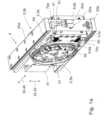
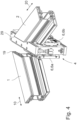
- FIG 1a the holder 4, as used for example in the method according to the invention or the device according to the invention or the machine according to the invention, is shown schematically.
- the holder 4 is essentially cuboid-shaped. Drives not shown here cause the holder 4 to be movable in a plane that is parallel or identical to the welding surface (that is the plane onto which the profile bars to be welded are welded); this is shown with the double arrows 30, 40 and 32, 42 that are orthogonal (in particular at right angles) to one another.
- the holder 4 has a frame 41.
- the two milling cutters 5, 5a, 5b and their drives or their common drive are mounted in the frame 41.
- the frame 41 also indirectly accommodates the parting knives 3.
- the parting knives 3 are each arranged on a knife holder 6, 6a, 6b.
- the Figure 1a , 1b The holder 4 shown is used for the simultaneous machining of the two profile bars 1, 2, which is why the holder 4 is double-equipped, i.e. has two milling cutters 5, 5a, 5b and also two knife holders 6, 6a, 6b.
- the milling cutters 5, 5a, 5b and also the two knife holders 6, 6a, 6b are preferably arranged symmetrically on the large side surfaces of the holder 4.
- the milling cutter 5, 5a, 5b is designed as a face milling cutter.
- the cutting edges 50 of the milling cutter 5, 5a, 5b are located at the axial end of the milling body and extend radially, in each case relative to the rotation axis 51 of the milling cutter 5.
- the knife holders 6, 6a, 6b are located to the side and, when in use, horizontally next to the milling cutters 5, 5a, 5b.
- two parting knives 3, 3a, 3c are arranged on the knife holder 6a.
- the second knife holder 6b which is hidden here, is also equipped with two parting knives 3.
- a first parting knife 3a is located at the top, the second,
- the lower parting knife 3c is located on the opposite side, at the bottom of the knife holder 6a.
- the two parting knives 3a, 3c are arranged symmetrically on the knife holder 6a, i.e. in the upper and lower areas.
- the knife holder 6, 6a is limited by a plate edge 60, the parting knives 3a, 3c protrude slightly beyond the respective plate edge 60.
- the discharge channels 70a and 70c are located behind the parting knives 3a, 3c in the cutting direction. These are part of the suction device and reliably ensure that the separated chips are immediately discharged and removed from the processing point.
- a suction device is also provided for the chips produced by the milling cutters 5, 5a, 5b, the channels of which are connected to the discharge channels 70a and 70c.
- a quick-change device 61 is used for the reliable fastening of the parting knife 3 on the knife holder 6.
- guide rail feet 63a, 63b which cooperate with guide rails of the device (not shown here) to hold and guide them.
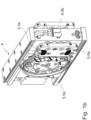
- Pressure lines 62a and 62b are marked, each of which is connected to a working cylinder. If the pressure lines 62a, 62b are subjected to pressure (pneumatic or hydraulic), the piston in the working cylinder expands and moves the knife holders 6, 6a, 6b from the Figure 1a shown resting position to the one in Figure 1b shown working position.
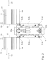
- Figure 2 shows the second step of processing the profile bars 1,2 with the parting knives 3.
- the holder 4 is partially positioned below the two profile bars 1,2.
- the knife holders 6, 6a, 6b are in the extended working position such that the respective parting knives 3, 3a, 3b can preferably act on the miter areas 11,21 of the profile bars 1,2.
- Figure 2 the second step of processing.
- the first step has already been carried out, because a bevel has already been machined into the upper side 13,23 of the first profile bar 1 or second profile bar 2 on the profile edge 19,29 by the lower parting knives 3,3c, 3d.
- the lower parting knives 3, 3c, 3d are therefore intended to machine the profile edge 19,29 on the profile top 13,23.
- the upper parting knives 3, 3a, 3b are intended to provide corresponding machining on the profile edge 19,29 on the profile bottom 14,24. It is advantageous that the profile bars 1,2 are arranged parallel to their longitudinal extension on a CNC axis and can thus be positioned with high precision. This is indicated by the arrows 10,20.
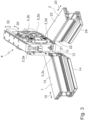
- Figure 4 essentially corresponds to the view in Figure 2 , only that in Figure 4 a three-dimensional view is selected. However, the editing situation is the same.
- a particular clever feature of the proposal is that the two profile bars 1,2 to be welded can be processed simultaneously using one holder 4. Processing preferably takes place simultaneously, which increases efficiency.
- the high positioning capability of the profile bars 1,2 thanks to their clamping devices is also used in order to be able to process the miter surfaces with high precision, but also to position the profile bars in such a way that the profile edges 19,29 can be processed as desired.
Landscapes
- Engineering & Computer Science (AREA)
- Mechanical Engineering (AREA)
- Physics & Mathematics (AREA)
- Thermal Sciences (AREA)
- Milling Processes (AREA)
- Laser Beam Processing (AREA)
Claims (10)
- Procédé de soudage d'une première barre profilée en matière plastique (1) avec une deuxième barre profilée (2) constituée de matière plastique, le procédé comprenant les étapes suivantes :▪ Mise à disposition de la première barre profilée (1) et de la deuxième barre profilée (2) ;▪ Usinage d'au moins une barre profilée (1, 2), en particulier dans sa zone d'onglet (11, 21), avec un couteau à tronçonner (3), l'arête de profilé (19, 29) qui délimite le côté extérieur du profilé, en particulier le côté supérieur du profilé (13, 23), le côté inférieur du profilé (14, 24), la feuillure intérieure, ou le coin extérieur, et la surface d'onglet de la barre profilée (1, 2), par le couteau à tronçonner (3), un logement de couteau (6, 6a, 6b) étant prévu, qui reçoit le couteau à tronçonner (3), un support (4) étant prévu, qui porte le couteau à tronçonner (3), le logement de couteau (6, 6a, 6b) étant logé de manière mobile sur le support (4) et pouvant être amené dans au moins deux positions différentes par un entraînement ;▪ le chauffage des barres profilées (1, 2) au moins sur leurs surfaces à onglet, la barre profilée (1, 2) étant en outre usinée par une fraise (5, 5a, 5b) avant le chauffage et les copeaux générés par le couteau à tronçonner (3) ou la fraise (5, 5a, 5b) étant aspirés ;▪ la mise en contact de la surface d'onglet de la première barre profilée (1) avec la surface d'onglet de la deuxième barre profilée (2) de telle sorte que les zones chauffées des surfaces d'onglet donnent une liaison par adhérence de matériau entre la première et la deuxième barre profilée (1, 2).
- Procédé selon la revendication 1, caractérisé en ce que les barres profilées (1, 2) sont mises à disposition, chacune serrée sur un dispositif de serrage, et au moins un dispositif de serrage avec le profilé serré (1, 2) se déplace pendant l'usinage et/ou l'usinage de la barre profilée (1, 2) par le couteau à tronçonner (3) s'effectue en une ou plusieurs étapes.
- Procédé selon l'une des revendications précédentes, caractérisé en ce que, simultanément, un premier couteau de tronçonnage (3a) usine la première barre profilée (1) et un deuxième couteau de tronçonnage (3c) usine la deuxième barre profilée (2), tandis que l'arête de profilé (19, 29), qui délimite la face extérieure du profilé, en particulier la face supérieure (13, 23), la face inférieure (14, 24) du profilé, la feuillure intérieure, ou l'angle extérieur, et la surface à onglet de la barre profilée (1, 2), est usinée par le couteau de tronçonnage (3).
- Procédé selon l'une des revendications précédentes, caractérisé en ce que, avant le chauffage, la surface d'onglet de la barre profilée (1, 2) est usinée par une fraise à surfacer en tant que fraise (5, 5a, 5b).
- Dispositif pour le soudage d'une première barre profilée (1) constituée de matière plastique avec une deuxième barre profilée (2) constituée de matière plastique,▪ le dispositif présentant respectivement un dispositif de serrage mobile, en particulier le long d'au moins une direction spatiale (10, 20), pour le maintien ou le positionnement de la barre profilée respective (1, 2), ainsi qu'un couteau à découper (3) pour l'usinage de la zone en onglet (11, 21) de la barre profilée (1, 2),▪ le couteau à tronçonner (3) étant conçu pour usiner l'arête du profilé qui délimite le côté extérieur du profilé, en particulier le côté supérieur, le côté inférieur du profilé, la feuillure intérieure, ou l'angle extérieur, et la surface à onglet de la barre profilée (1, 2),▪ un support (4) étant prévu, qui porte la lame de tronçonnage (3),▪ la lame de tronçonnage (3) étant montée de manière à pouvoir être déplacée et positionnée au moins le long d'une direction spatiale (30),▪ un logement de lame (6) étant prévu, qui reçoit la au moins une lame de tronçonnage (3), et▪ le logement de lame (6) étant logé de manière mobile sur le support (4) et pouvant être amené dans au moins deux positions différentes par un entraînement, et▪ un miroir chauffant étant présent, lequel est monté de manière à pouvoir être déplacé et positionné au moins le long d'une direction spatiale (30) et est prévu pour le chauffage d'au moins la surface en onglet (12, 22) de la barre profilée (1, 2) ou des barres profilées (1, 2), et▪ une fraise (5) étant prévue, laquelle est conçue pour usiner la barre profilée (1, 2) avant le chauffage, un dispositif d'aspiration étant prévu pour l'aspiration des copeaux générés par la fraise (5) et/ou la lame de tronçonnage (3).
- Dispositif selon la revendication 5, caractérisé en ce que le support (4) porte également au moins une fraise (5), en particulier une fraise à surfacer.
- Dispositif selon l'une des revendications précédentes 5 à 6, caractérisé en ce que le support (4) porte au moins une première et une deuxième lame de tronçonnage (3, 3a, 3b, 3c, 3d) et/ou une première et une deuxième fraise, notamment une fraise à surfacer.
- Dispositif selon l'une des revendications précédentes 5 à 7, caractérisé en ce qu'un dispositif de changement rapide (31) pour le couteau de tronçonnage (3) est prévu sur le support (4) ou le logement de couteau (6) et/ou un élément de balayage est prévu latéralement à côté du couteau de tronçonnage (3) pour la détection du contour du profil.
- Dispositif selon l'une des revendications précédentes 5 à 8, caractérisé en ce que le support (4) peut être déplacé dans une surface (30, 32) par des entraînements correspondants.
- Machine pour la fabrication d'un cadre de fenêtre ou d'une partie d'un cadre de fenêtre, ladite machine comprenant au moins un dispositif selon l'une quelconque des revendications précédentes 5 à 9.
Applications Claiming Priority (1)
| Application Number | Priority Date | Filing Date | Title |
|---|---|---|---|
| DE102018133638.1A DE102018133638A1 (de) | 2018-12-27 | 2018-12-27 | Verfahren und Vorrichtung für das Verschweißen von Profilstäben |
Publications (3)
| Publication Number | Publication Date |
|---|---|
| EP3674065A1 EP3674065A1 (fr) | 2020-07-01 |
| EP3674065C0 EP3674065C0 (fr) | 2025-02-05 |
| EP3674065B1 true EP3674065B1 (fr) | 2025-02-05 |
Family
ID=69005420
Family Applications (1)
| Application Number | Title | Priority Date | Filing Date |
|---|---|---|---|
| EP19219025.4A Active EP3674065B1 (fr) | 2018-12-27 | 2019-12-20 | Procédé et dispositif de soudage de barres profilées |
Country Status (4)
| Country | Link |
|---|---|
| EP (1) | EP3674065B1 (fr) |
| DE (1) | DE102018133638A1 (fr) |
| ES (1) | ES3016962T3 (fr) |
| PL (1) | PL3674065T3 (fr) |
Families Citing this family (5)
| Publication number | Priority date | Publication date | Assignee | Title |
|---|---|---|---|---|
| DE102020123272B3 (de) | 2020-09-07 | 2021-10-21 | Rotox Besitz- Und Verwaltungsgesellschaft Mbh | Verfahren und Vorrichtung zum Verschweißen von wenigstens zwei Profilen für Fenster- oder Türrahmen bzw. -flügeln |
| IT202100011810A1 (it) * | 2021-05-07 | 2022-11-07 | Graf Synergy Srl | Macchina per la saldatura di profilati in materiale plastico |
| DE102021006421A1 (de) | 2021-12-30 | 2023-07-06 | Urban Gesellschaft mit beschränkter Haftung & Co. Maschinenbau Kommanditgesellschaft | Fräseranordnung |
| EP4659940A1 (fr) | 2024-06-06 | 2025-12-10 | Awgtech Spolka z Ograniczona Odpowiedzialnoscia | Procédé de soudage, dispositifs et machine de soudage |
| DE102024119821A1 (de) * | 2024-07-11 | 2026-01-15 | Urban Gesellschaft mit beschränkter Haftung & Co. Maschinenbau Kommanditgesellschaft | Fräseranordung mit vorauseilendem Zusatzfräser |
Family Cites Families (5)
| Publication number | Priority date | Publication date | Assignee | Title |
|---|---|---|---|---|
| US3186891A (en) * | 1962-05-14 | 1965-06-01 | Gen Motors Corp | Apparatus for joining thermoplastic elements |
| DE4018145A1 (de) * | 1990-06-06 | 1991-12-12 | Bernd Eisenbach | Verputzvorrichtung fuer fensterrahmen o. dgl. |
| JPH0780940A (ja) * | 1993-09-13 | 1995-03-28 | Sekisui Chem Co Ltd | 管材の融着接合方法 |
| GB2376656A (en) * | 2001-06-21 | 2002-12-24 | Gti Kombimatec Machines Ltd | Removing notches from the weld face areas of components, to locally reduce waste sprue produced during thermal bonding, apparatus, method & preparation |
| DE102016104806A1 (de) * | 2015-03-24 | 2016-11-24 | Urban Gmbh & Co. Maschinenbau Kg | Verfahren zum Verbinden von Profilstücken |
-
2018
- 2018-12-27 DE DE102018133638.1A patent/DE102018133638A1/de active Pending
-
2019
- 2019-12-20 EP EP19219025.4A patent/EP3674065B1/fr active Active
- 2019-12-20 ES ES19219025T patent/ES3016962T3/es active Active
- 2019-12-20 PL PL19219025.4T patent/PL3674065T3/pl unknown
Also Published As
| Publication number | Publication date |
|---|---|
| DE102018133638A1 (de) | 2020-07-02 |
| PL3674065T3 (pl) | 2025-05-12 |
| ES3016962T3 (en) | 2025-05-12 |
| EP3674065A1 (fr) | 2020-07-01 |
| EP3674065C0 (fr) | 2025-02-05 |
Similar Documents
| Publication | Publication Date | Title |
|---|---|---|
| EP3674065B1 (fr) | Procédé et dispositif de soudage de barres profilées | |
| EP3072615B1 (fr) | Tete de fraisage | |
| EP3072668B2 (fr) | Procede et dispositif de raccordement de pieces profilees | |
| EP3412393A2 (fr) | Dispositifs et procédé de chanfreinage d'une pièce à denture intérieure | |
| DE3420531A1 (de) | Drehmaschine | |
| WO2018055190A1 (fr) | Procédé, machine-outil et outil de découpage pour le découpage continu à course multiple de pièces en forme de plaque | |
| EP1317974B1 (fr) | Procédé et machine pour fendre à plusieurs courses des pièces formés en plaque, en particulier des tôles | |
| DE102016118175B4 (de) | Werkzeugmaschine und Verfahren zum Bearbeiten von plattenförmigen Werkstücken | |
| EP1894654B1 (fr) | Procédé et unité de traitement destinée au traitement des liaisons angulaires de cadres soudés à partir de pièces de profilés | |
| EP4008508A1 (fr) | Procédé de sciage d'au moins une plaque | |
| EP1125670B1 (fr) | Dispositif à ébarber, en particulier pour des cordons de soudure | |
| EP1537970B1 (fr) | Dispositif d'ébarbage | |
| DE102016120139B4 (de) | Verfahren, Werkzeugmaschine und Schlitzwerkzeug zum mehrhubig fortschreitenden Schlitzen von plattenförmigen Werkstücken | |
| DE29508355U1 (de) | Vorrichtung zum Zerlegen von Baumstämmen in Holzerzeugnisse und Fräskopf für eine solche Vorrichtung | |
| WO2019057658A1 (fr) | Procédé d'usinage de pièces, produit programme-informatique, et installation d'usinage de pièces | |
| EP0978339B1 (fr) | Dispositif de coupe des profilés de fenêtres ou portes | |
| DE2415006A1 (de) | Verfahren und vorrichtung zur herstellung von fensterrahmen mit glashalteleiste aus holz | |
| DE19721521C2 (de) | Numerisch gesteuerte Zapfenschneidmaschine | |
| EP4667194A1 (fr) | Dispositif et procédé de fabrication d'une liaison profilée | |
| DE2238607A1 (de) | Verfahren und vorrichtung zur bearbeitung von profilen fuer turbinenschaufelfuesse | |
| DE102011102793B3 (de) | Verfahren zur Bearbeitung der Stirnseiten von Werkstücken aus Holz, Kunststoff und dergleichen | |
| EP3575068A1 (fr) | Dispositif et procédé de raccordement de pièces profilées | |
| CH622580A5 (en) | Method and device for manufacturing the corner connections of window frames and door frames | |
| DE2261239A1 (de) | Vorrichtung zum spanabhebenden bearbeiten einer werkstueckoberflaeche | |
| DE102020116297A1 (de) | Verfahren und Vorrichtung zum Bearbeiten eines Endbereichs eines Profils |
Legal Events
| Date | Code | Title | Description |
|---|---|---|---|
| PUAI | Public reference made under article 153(3) epc to a published international application that has entered the european phase |
Free format text: ORIGINAL CODE: 0009012 |
|
| STAA | Information on the status of an ep patent application or granted ep patent |
Free format text: STATUS: THE APPLICATION HAS BEEN PUBLISHED |
|
| AK | Designated contracting states |
Kind code of ref document: A1 Designated state(s): AL AT BE BG CH CY CZ DE DK EE ES FI FR GB GR HR HU IE IS IT LI LT LU LV MC MK MT NL NO PL PT RO RS SE SI SK SM TR |
|
| AX | Request for extension of the european patent |
Extension state: BA ME |
|
| STAA | Information on the status of an ep patent application or granted ep patent |
Free format text: STATUS: REQUEST FOR EXAMINATION WAS MADE |
|
| 17P | Request for examination filed |
Effective date: 20201214 |
|
| RBV | Designated contracting states (corrected) |
Designated state(s): AL AT BE BG CH CY CZ DE DK EE ES FI FR GB GR HR HU IE IS IT LI LT LU LV MC MK MT NL NO PL PT RO RS SE SI SK SM TR |
|
| STAA | Information on the status of an ep patent application or granted ep patent |
Free format text: STATUS: EXAMINATION IS IN PROGRESS |
|
| 17Q | First examination report despatched |
Effective date: 20230215 |
|
| RIC1 | Information provided on ipc code assigned before grant |
Ipc: B29K 27/06 20060101ALN20240626BHEP Ipc: B29C 37/04 20060101ALN20240626BHEP Ipc: E06B 3/96 20060101ALN20240626BHEP Ipc: B23C 3/12 20060101ALI20240626BHEP Ipc: B29C 65/20 20060101AFI20240626BHEP |
|
| GRAP | Despatch of communication of intention to grant a patent |
Free format text: ORIGINAL CODE: EPIDOSNIGR1 |
|
| STAA | Information on the status of an ep patent application or granted ep patent |
Free format text: STATUS: GRANT OF PATENT IS INTENDED |
|
| INTG | Intention to grant announced |
Effective date: 20240805 |
|
| GRAS | Grant fee paid |
Free format text: ORIGINAL CODE: EPIDOSNIGR3 |
|
| GRAA | (expected) grant |
Free format text: ORIGINAL CODE: 0009210 |
|
| STAA | Information on the status of an ep patent application or granted ep patent |
Free format text: STATUS: THE PATENT HAS BEEN GRANTED |
|
| AK | Designated contracting states |
Kind code of ref document: B1 Designated state(s): AL AT BE BG CH CY CZ DE DK EE ES FI FR GB GR HR HU IE IS IT LI LT LU LV MC MK MT NL NO PL PT RO RS SE SI SK SM TR |
|
| REG | Reference to a national code |
Ref country code: GB Ref legal event code: FG4D Free format text: NOT ENGLISH |
|
| REG | Reference to a national code |
Ref country code: CH Ref legal event code: EP |
|
| REG | Reference to a national code |
Ref country code: DE Ref legal event code: R096 Ref document number: 502019012901 Country of ref document: DE |
|
| REG | Reference to a national code |
Ref country code: IE Ref legal event code: FG4D Free format text: LANGUAGE OF EP DOCUMENT: GERMAN |
|
| U01 | Request for unitary effect filed |
Effective date: 20250303 |
|
| U07 | Unitary effect registered |
Designated state(s): AT BE BG DE DK EE FI FR IT LT LU LV MT NL PT RO SE SI Effective date: 20250310 |
|
| REG | Reference to a national code |
Ref country code: ES Ref legal event code: FG2A Ref document number: 3016962 Country of ref document: ES Kind code of ref document: T3 Effective date: 20250512 |
|
| PG25 | Lapsed in a contracting state [announced via postgrant information from national office to epo] |
Ref country code: RS Free format text: LAPSE BECAUSE OF FAILURE TO SUBMIT A TRANSLATION OF THE DESCRIPTION OR TO PAY THE FEE WITHIN THE PRESCRIBED TIME-LIMIT Effective date: 20250505 |
|
| PG25 | Lapsed in a contracting state [announced via postgrant information from national office to epo] |
Ref country code: NO Free format text: LAPSE BECAUSE OF FAILURE TO SUBMIT A TRANSLATION OF THE DESCRIPTION OR TO PAY THE FEE WITHIN THE PRESCRIBED TIME-LIMIT Effective date: 20250505 Ref country code: IS Free format text: LAPSE BECAUSE OF FAILURE TO SUBMIT A TRANSLATION OF THE DESCRIPTION OR TO PAY THE FEE WITHIN THE PRESCRIBED TIME-LIMIT Effective date: 20250605 |
|
| PG25 | Lapsed in a contracting state [announced via postgrant information from national office to epo] |
Ref country code: HR Free format text: LAPSE BECAUSE OF FAILURE TO SUBMIT A TRANSLATION OF THE DESCRIPTION OR TO PAY THE FEE WITHIN THE PRESCRIBED TIME-LIMIT Effective date: 20250205 |
|
| PG25 | Lapsed in a contracting state [announced via postgrant information from national office to epo] |
Ref country code: GR Free format text: LAPSE BECAUSE OF FAILURE TO SUBMIT A TRANSLATION OF THE DESCRIPTION OR TO PAY THE FEE WITHIN THE PRESCRIBED TIME-LIMIT Effective date: 20250506 |
|
| PG25 | Lapsed in a contracting state [announced via postgrant information from national office to epo] |
Ref country code: SM Free format text: LAPSE BECAUSE OF FAILURE TO SUBMIT A TRANSLATION OF THE DESCRIPTION OR TO PAY THE FEE WITHIN THE PRESCRIBED TIME-LIMIT Effective date: 20250205 |
|
| PG25 | Lapsed in a contracting state [announced via postgrant information from national office to epo] |
Ref country code: SK Free format text: LAPSE BECAUSE OF FAILURE TO SUBMIT A TRANSLATION OF THE DESCRIPTION OR TO PAY THE FEE WITHIN THE PRESCRIBED TIME-LIMIT Effective date: 20250205 |
|
| PLBE | No opposition filed within time limit |
Free format text: ORIGINAL CODE: 0009261 |
|
| STAA | Information on the status of an ep patent application or granted ep patent |
Free format text: STATUS: NO OPPOSITION FILED WITHIN TIME LIMIT |
|
| PGFP | Annual fee paid to national office [announced via postgrant information from national office to epo] |
Ref country code: GB Payment date: 20251219 Year of fee payment: 7 |
|
| 26N | No opposition filed |
Effective date: 20251106 |
|
| PGFP | Annual fee paid to national office [announced via postgrant information from national office to epo] |
Ref country code: TR Payment date: 20251216 Year of fee payment: 7 |
|
| PGFP | Annual fee paid to national office [announced via postgrant information from national office to epo] |
Ref country code: CZ Payment date: 20251217 Year of fee payment: 7 |
|
| PGFP | Annual fee paid to national office [announced via postgrant information from national office to epo] |
Ref country code: PL Payment date: 20251210 Year of fee payment: 7 |
|
| U20 | Renewal fee for the european patent with unitary effect paid |
Year of fee payment: 7 Effective date: 20251230 |
|
| PGFP | Annual fee paid to national office [announced via postgrant information from national office to epo] |
Ref country code: ES Payment date: 20260130 Year of fee payment: 7 |