EP3674070A1 - Dispositif d'extrusion de caoutchouc et procédé de fabrication d'un objet extrudé en caoutchouc - Google Patents
Dispositif d'extrusion de caoutchouc et procédé de fabrication d'un objet extrudé en caoutchouc Download PDFInfo
- Publication number
- EP3674070A1 EP3674070A1 EP18849262.3A EP18849262A EP3674070A1 EP 3674070 A1 EP3674070 A1 EP 3674070A1 EP 18849262 A EP18849262 A EP 18849262A EP 3674070 A1 EP3674070 A1 EP 3674070A1
- Authority
- EP
- European Patent Office
- Prior art keywords
- extrusion
- flow path
- rubber
- control plate
- head
- Prior art date
- Legal status (The legal status is an assumption and is not a legal conclusion. Google has not performed a legal analysis and makes no representation as to the accuracy of the status listed.)
- Granted
Links
Images


Classifications
-
- B—PERFORMING OPERATIONS; TRANSPORTING
- B29—WORKING OF PLASTICS; WORKING OF SUBSTANCES IN A PLASTIC STATE IN GENERAL
- B29B—PREPARATION OR PRETREATMENT OF THE MATERIAL TO BE SHAPED; MAKING GRANULES OR PREFORMS; RECOVERY OF PLASTICS OR OTHER CONSTITUENTS OF WASTE MATERIAL CONTAINING PLASTICS
- B29B7/00—Mixing; Kneading
- B29B7/74—Mixing; Kneading using other mixers or combinations of mixers, e.g. of dissimilar mixers ; Plant
- B29B7/7476—Systems, i.e. flow charts or diagrams; Plants
- B29B7/7495—Systems, i.e. flow charts or diagrams; Plants for mixing rubber
-
- B—PERFORMING OPERATIONS; TRANSPORTING
- B29—WORKING OF PLASTICS; WORKING OF SUBSTANCES IN A PLASTIC STATE IN GENERAL
- B29C—SHAPING OR JOINING OF PLASTICS; SHAPING OF MATERIAL IN A PLASTIC STATE, NOT OTHERWISE PROVIDED FOR; AFTER-TREATMENT OF THE SHAPED PRODUCTS, e.g. REPAIRING
- B29C48/00—Extrusion moulding, i.e. expressing the moulding material through a die or nozzle which imparts the desired form; Apparatus therefor
- B29C48/25—Component parts, details or accessories; Auxiliary operations
- B29C48/266—Means for allowing relative movements between the apparatus parts, e.g. for twisting the extruded article or for moving the die along a surface to be coated
-
- B—PERFORMING OPERATIONS; TRANSPORTING
- B29—WORKING OF PLASTICS; WORKING OF SUBSTANCES IN A PLASTIC STATE IN GENERAL
- B29B—PREPARATION OR PRETREATMENT OF THE MATERIAL TO BE SHAPED; MAKING GRANULES OR PREFORMS; RECOVERY OF PLASTICS OR OTHER CONSTITUENTS OF WASTE MATERIAL CONTAINING PLASTICS
- B29B7/00—Mixing; Kneading
- B29B7/30—Mixing; Kneading continuous, with mechanical mixing or kneading devices
- B29B7/58—Component parts, details or accessories; Auxiliary operations
- B29B7/72—Measuring, controlling or regulating
-
- B—PERFORMING OPERATIONS; TRANSPORTING
- B29—WORKING OF PLASTICS; WORKING OF SUBSTANCES IN A PLASTIC STATE IN GENERAL
- B29C—SHAPING OR JOINING OF PLASTICS; SHAPING OF MATERIAL IN A PLASTIC STATE, NOT OTHERWISE PROVIDED FOR; AFTER-TREATMENT OF THE SHAPED PRODUCTS, e.g. REPAIRING
- B29C48/00—Extrusion moulding, i.e. expressing the moulding material through a die or nozzle which imparts the desired form; Apparatus therefor
- B29C48/03—Extrusion moulding, i.e. expressing the moulding material through a die or nozzle which imparts the desired form; Apparatus therefor characterised by the shape of the extruded material at extrusion
- B29C48/07—Flat, e.g. panels
-
- B—PERFORMING OPERATIONS; TRANSPORTING
- B29—WORKING OF PLASTICS; WORKING OF SUBSTANCES IN A PLASTIC STATE IN GENERAL
- B29C—SHAPING OR JOINING OF PLASTICS; SHAPING OF MATERIAL IN A PLASTIC STATE, NOT OTHERWISE PROVIDED FOR; AFTER-TREATMENT OF THE SHAPED PRODUCTS, e.g. REPAIRING
- B29C48/00—Extrusion moulding, i.e. expressing the moulding material through a die or nozzle which imparts the desired form; Apparatus therefor
- B29C48/03—Extrusion moulding, i.e. expressing the moulding material through a die or nozzle which imparts the desired form; Apparatus therefor characterised by the shape of the extruded material at extrusion
- B29C48/12—Articles with an irregular circumference when viewed in cross-section, e.g. window profiles
-
- B—PERFORMING OPERATIONS; TRANSPORTING
- B29—WORKING OF PLASTICS; WORKING OF SUBSTANCES IN A PLASTIC STATE IN GENERAL
- B29C—SHAPING OR JOINING OF PLASTICS; SHAPING OF MATERIAL IN A PLASTIC STATE, NOT OTHERWISE PROVIDED FOR; AFTER-TREATMENT OF THE SHAPED PRODUCTS, e.g. REPAIRING
- B29C48/00—Extrusion moulding, i.e. expressing the moulding material through a die or nozzle which imparts the desired form; Apparatus therefor
- B29C48/25—Component parts, details or accessories; Auxiliary operations
- B29C48/30—Extrusion nozzles or dies
- B29C48/302—Extrusion nozzles or dies being adjustable, i.e. having adjustable exit sections
-
- B—PERFORMING OPERATIONS; TRANSPORTING
- B29—WORKING OF PLASTICS; WORKING OF SUBSTANCES IN A PLASTIC STATE IN GENERAL
- B29C—SHAPING OR JOINING OF PLASTICS; SHAPING OF MATERIAL IN A PLASTIC STATE, NOT OTHERWISE PROVIDED FOR; AFTER-TREATMENT OF THE SHAPED PRODUCTS, e.g. REPAIRING
- B29C48/00—Extrusion moulding, i.e. expressing the moulding material through a die or nozzle which imparts the desired form; Apparatus therefor
- B29C48/25—Component parts, details or accessories; Auxiliary operations
- B29C48/30—Extrusion nozzles or dies
- B29C48/305—Extrusion nozzles or dies having a wide opening, e.g. for forming sheets
- B29C48/31—Extrusion nozzles or dies having a wide opening, e.g. for forming sheets being adjustable, i.e. having adjustable exit sections
-
- B—PERFORMING OPERATIONS; TRANSPORTING
- B29—WORKING OF PLASTICS; WORKING OF SUBSTANCES IN A PLASTIC STATE IN GENERAL
- B29C—SHAPING OR JOINING OF PLASTICS; SHAPING OF MATERIAL IN A PLASTIC STATE, NOT OTHERWISE PROVIDED FOR; AFTER-TREATMENT OF THE SHAPED PRODUCTS, e.g. REPAIRING
- B29C48/00—Extrusion moulding, i.e. expressing the moulding material through a die or nozzle which imparts the desired form; Apparatus therefor
- B29C48/25—Component parts, details or accessories; Auxiliary operations
- B29C48/36—Means for plasticising or homogenising the moulding material or forcing it through the nozzle or die
- B29C48/395—Means for plasticising or homogenising the moulding material or forcing it through the nozzle or die using screws surrounded by a cooperating barrel, e.g. single screw extruders
- B29C48/397—Means for plasticising or homogenising the moulding material or forcing it through the nozzle or die using screws surrounded by a cooperating barrel, e.g. single screw extruders using a single screw
-
- B—PERFORMING OPERATIONS; TRANSPORTING
- B29—WORKING OF PLASTICS; WORKING OF SUBSTANCES IN A PLASTIC STATE IN GENERAL
- B29C—SHAPING OR JOINING OF PLASTICS; SHAPING OF MATERIAL IN A PLASTIC STATE, NOT OTHERWISE PROVIDED FOR; AFTER-TREATMENT OF THE SHAPED PRODUCTS, e.g. REPAIRING
- B29C48/00—Extrusion moulding, i.e. expressing the moulding material through a die or nozzle which imparts the desired form; Apparatus therefor
- B29C48/25—Component parts, details or accessories; Auxiliary operations
- B29C48/92—Measuring, controlling or regulating
-
- B—PERFORMING OPERATIONS; TRANSPORTING
- B29—WORKING OF PLASTICS; WORKING OF SUBSTANCES IN A PLASTIC STATE IN GENERAL
- B29B—PREPARATION OR PRETREATMENT OF THE MATERIAL TO BE SHAPED; MAKING GRANULES OR PREFORMS; RECOVERY OF PLASTICS OR OTHER CONSTITUENTS OF WASTE MATERIAL CONTAINING PLASTICS
- B29B7/00—Mixing; Kneading
- B29B7/30—Mixing; Kneading continuous, with mechanical mixing or kneading devices
- B29B7/34—Mixing; Kneading continuous, with mechanical mixing or kneading devices with movable mixing or kneading devices
- B29B7/38—Mixing; Kneading continuous, with mechanical mixing or kneading devices with movable mixing or kneading devices rotary
- B29B7/40—Mixing; Kneading continuous, with mechanical mixing or kneading devices with movable mixing or kneading devices rotary with single shaft
- B29B7/42—Mixing; Kneading continuous, with mechanical mixing or kneading devices with movable mixing or kneading devices rotary with single shaft with screw or helix
-
- B—PERFORMING OPERATIONS; TRANSPORTING
- B29—WORKING OF PLASTICS; WORKING OF SUBSTANCES IN A PLASTIC STATE IN GENERAL
- B29C—SHAPING OR JOINING OF PLASTICS; SHAPING OF MATERIAL IN A PLASTIC STATE, NOT OTHERWISE PROVIDED FOR; AFTER-TREATMENT OF THE SHAPED PRODUCTS, e.g. REPAIRING
- B29C2948/00—Indexing scheme relating to extrusion moulding
- B29C2948/92—Measuring, controlling or regulating
- B29C2948/92009—Measured parameter
- B29C2948/92076—Position, e.g. linear or angular
-
- B—PERFORMING OPERATIONS; TRANSPORTING
- B29—WORKING OF PLASTICS; WORKING OF SUBSTANCES IN A PLASTIC STATE IN GENERAL
- B29C—SHAPING OR JOINING OF PLASTICS; SHAPING OF MATERIAL IN A PLASTIC STATE, NOT OTHERWISE PROVIDED FOR; AFTER-TREATMENT OF THE SHAPED PRODUCTS, e.g. REPAIRING
- B29C2948/00—Indexing scheme relating to extrusion moulding
- B29C2948/92—Measuring, controlling or regulating
- B29C2948/92009—Measured parameter
- B29C2948/92114—Dimensions
- B29C2948/92171—Distortion, shrinkage, dilatation, swell or warpage
-
- B—PERFORMING OPERATIONS; TRANSPORTING
- B29—WORKING OF PLASTICS; WORKING OF SUBSTANCES IN A PLASTIC STATE IN GENERAL
- B29C—SHAPING OR JOINING OF PLASTICS; SHAPING OF MATERIAL IN A PLASTIC STATE, NOT OTHERWISE PROVIDED FOR; AFTER-TREATMENT OF THE SHAPED PRODUCTS, e.g. REPAIRING
- B29C2948/00—Indexing scheme relating to extrusion moulding
- B29C2948/92—Measuring, controlling or regulating
- B29C2948/92323—Location or phase of measurement
- B29C2948/92361—Extrusion unit
- B29C2948/92409—Die; Nozzle zone
-
- B—PERFORMING OPERATIONS; TRANSPORTING
- B29—WORKING OF PLASTICS; WORKING OF SUBSTANCES IN A PLASTIC STATE IN GENERAL
- B29C—SHAPING OR JOINING OF PLASTICS; SHAPING OF MATERIAL IN A PLASTIC STATE, NOT OTHERWISE PROVIDED FOR; AFTER-TREATMENT OF THE SHAPED PRODUCTS, e.g. REPAIRING
- B29C2948/00—Indexing scheme relating to extrusion moulding
- B29C2948/92—Measuring, controlling or regulating
- B29C2948/92504—Controlled parameter
- B29C2948/92571—Position, e.g. linear or angular
-
- B—PERFORMING OPERATIONS; TRANSPORTING
- B29—WORKING OF PLASTICS; WORKING OF SUBSTANCES IN A PLASTIC STATE IN GENERAL
- B29C—SHAPING OR JOINING OF PLASTICS; SHAPING OF MATERIAL IN A PLASTIC STATE, NOT OTHERWISE PROVIDED FOR; AFTER-TREATMENT OF THE SHAPED PRODUCTS, e.g. REPAIRING
- B29C2948/00—Indexing scheme relating to extrusion moulding
- B29C2948/92—Measuring, controlling or regulating
- B29C2948/92504—Controlled parameter
- B29C2948/92609—Dimensions
- B29C2948/92666—Distortion, shrinkage, dilatation, swell or warpage
-
- B—PERFORMING OPERATIONS; TRANSPORTING
- B29—WORKING OF PLASTICS; WORKING OF SUBSTANCES IN A PLASTIC STATE IN GENERAL
- B29C—SHAPING OR JOINING OF PLASTICS; SHAPING OF MATERIAL IN A PLASTIC STATE, NOT OTHERWISE PROVIDED FOR; AFTER-TREATMENT OF THE SHAPED PRODUCTS, e.g. REPAIRING
- B29C2948/00—Indexing scheme relating to extrusion moulding
- B29C2948/92—Measuring, controlling or regulating
- B29C2948/92819—Location or phase of control
- B29C2948/92857—Extrusion unit
- B29C2948/92904—Die; Nozzle zone
-
- B—PERFORMING OPERATIONS; TRANSPORTING
- B29—WORKING OF PLASTICS; WORKING OF SUBSTANCES IN A PLASTIC STATE IN GENERAL
- B29C—SHAPING OR JOINING OF PLASTICS; SHAPING OF MATERIAL IN A PLASTIC STATE, NOT OTHERWISE PROVIDED FOR; AFTER-TREATMENT OF THE SHAPED PRODUCTS, e.g. REPAIRING
- B29C48/00—Extrusion moulding, i.e. expressing the moulding material through a die or nozzle which imparts the desired form; Apparatus therefor
- B29C48/03—Extrusion moulding, i.e. expressing the moulding material through a die or nozzle which imparts the desired form; Apparatus therefor characterised by the shape of the extruded material at extrusion
- B29C48/06—Rod-shaped
-
- B—PERFORMING OPERATIONS; TRANSPORTING
- B29—WORKING OF PLASTICS; WORKING OF SUBSTANCES IN A PLASTIC STATE IN GENERAL
- B29C—SHAPING OR JOINING OF PLASTICS; SHAPING OF MATERIAL IN A PLASTIC STATE, NOT OTHERWISE PROVIDED FOR; AFTER-TREATMENT OF THE SHAPED PRODUCTS, e.g. REPAIRING
- B29C48/00—Extrusion moulding, i.e. expressing the moulding material through a die or nozzle which imparts the desired form; Apparatus therefor
- B29C48/03—Extrusion moulding, i.e. expressing the moulding material through a die or nozzle which imparts the desired form; Apparatus therefor characterised by the shape of the extruded material at extrusion
- B29C48/131—Curved articles
Definitions
- the present invention relates to a rubber extrusion device and a method for manufacturing a rubber extrudate and particularly relates to a rubber extrusion device and a method for manufacturing a rubber extrudate capable of suppressing unintended curvature of a rubber extrudate while maintaining a predetermined position at which the rubber extrudate is extruded.
- an extrusion step is available in which unvulcanized rubber is extruded by a rubber extrusion device.
- a screw installed inside a rubber extrusion device plasticizes unvulcanized rubber and feeds plasticized unvulcanized rubber into an extrusion flow path formed in a head at a leading end.
- a die having an extrusion port with a desired shape is installed at the leading end of the head, and unvulcanized rubber passes through the extrusion port.
- a rubber extrudate formed into the desired shape is thus manufactured (for example, see Patent Documents 1 and 2).
- the object of the present invention is to provide a rubber extrusion device and a method for manufacturing a rubber extrudate capable of suppressing unintended curvature of a rubber extrudate while maintaining a predetermined position at which the rubber extrudate is extruded.
- a rubber extrusion device of an embodiment of the present invention includes: a cylinder with a cylindrical shape; a screw disposed in an internal space of the cylinder; a head being installed at a leading end of the cylinder and having an extrusion flow path that communicates with the internal space; a die being disposed in front of the extrusion flow path and having an extrusion port that communicates with the extrusion flow path, wherein the rubber extrusion device includes a control plate, the control plate being interposed between the head and the die and having an adjustment flow path that communicates with the extrusion flow path and the extrusion port, and includes a moving unit, the moving unit sliding the control plate along and between the head and the die; and by sliding the control plate, the position of a communication region of the extrusion flow path with respect to the adjustment flow path at a leading end opening of the extrusion flow path changes.
- a method for manufacturing a rubber extrudate of an embodiment of the present invention includes: feeding a rubber material into an internal space of a cylinder with a cylindrical shape; using a screw disposed in the internal space to extrude the rubber material forward while mixing and kneading the rubber material; feeding resultant unvulcanized rubber into an extrusion flow path formed in a head installed at a leading end of the cylinder; and extruding the unvulcanized rubber from an extrusion port as a rubber extrudate, the extrusion port being formed in a die disposed in front of the extrusion flow path, wherein a control plate, the control plate having an adjustment flow path that communicates with the extrusion flow path and the extrusion port, is interposed between the head and the die; the control plate is slid along and between the head and the die to change the position of a communication region of the extrusion flow path with respect to the adjustment flow path at a leading end opening of the extrusion flow path, setting the control plate at a desired position;
- the position of the communication region of the extrusion flow path with respect to the adjustment flow path of the control plate at the leading end opening of the extrusion flow path of the head changes. Accordingly, when the unvulcanized rubber passes through the extrusion flow path and the adjustment flow path and is extruded from the extrusion port, the pressure distribution (fluid flow distribution) changes, and the curvature of the rubber extrudate can be adjusted.
- the control plate such that the rubber extrudate is curved in a direction opposite to the direction of unintended curvature, the unintended curvature of the rubber extrudate can be suppressed.
- the position where the rubber extrudate is extruded can be maintained at a predetermined position. Accordingly, the line for conveying the rubber extrudate to the next step can be set to a given position, and thus it is not necessary to make a change to the conveying line to accommodate the sliding of the control plate.
- a rubber extrusion device and a method for manufacturing a rubber extrudate according to an embodiment of the present invention will be described below based on illustrated embodiments.
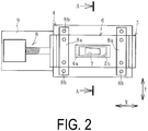
- a rubber extrusion device 1 of an embodiment of the present invention illustrated in FIG. 1 to FIG. 4 includes a cylinder 2 with a cylindrical shape, a screw 3 disposed inside the cylinder 2, and a head 4 disposed at a leading end of the cylinder 2.
- the head 4 includes an extrusion flow path 4a penetrating the head 4 in a longitudinal direction.
- a die 6 is attached in front of the head 4 with a control plate 5 interposed.
- the rubber extrusion device 1 includes a moving unit 8 that slides the control plate 5 along and between the head 4 and the die 6. Note that in FIG. 1 , the moving unit 8 and the like are omitted and not illustrated.
- the rubber extrusion device 1 further includes a sensor 10 and a control unit 11 to which detection data from the sensor 10 is input.
- a conveyor device 12 is disposed in front of the die 6.
- a horizontal direction and a vertical direction are indicated in an X arrow direction and a Y arrow direction, respectively, as a direction along and between the head 4 and the die 6.
- the X arrow direction and the Y arrow direction are orthogonal to each other, and the X arrow direction and the Y arrow direction are orthogonal to the direction in which the extrusion flow path 4a extends.
- the direction in which the control plate 5 slides is not limited to the X arrow direction or the Y arrow direction, and may be an oblique direction along the head 4 and the die 6.
- an internal space is narrower toward the front.
- the extrusion flow path 4a is in communication with the internal space of the cylinder 2.
- the control plate 5 is, for example, a metal plate-like body and has an adjustment flow path 5a penetrating the control plate 5 in the longitudinal direction.
- the die 6 has an extrusion port 7 penetrating the die 6 in the longitudinal direction.
- the extrusion port 7 has a trapezoidal shape extending in the width direction in a front view as illustrated in FIG. 2 and is formed into a left-right asymmetrical shape.
- the extrusion port 7 is not limited to this shape, and a desired shape such as a circle, an ellipse, a semicircle, a square, a rectangle, or the like is employed.
- the die 6 is fixed to the front of the head 4 via a holding member 8a.
- the die 6 is fixed by a plurality of fixing bolts 8b to two holding members 8a disposed at an interval in the horizontal direction of the die 6, and each one of the holding members 8a is fixed to the head 4 by the plurality of fixing bolts 8b.
- the extrusion flow path 4a, the adjustment flow path 5a, and the extrusion port 7 are in communication.
- the cross-sectional areas of the extrusion flow path 4a, the adjustment flow path 5a, and the extrusion port 7 are sequentially reduced.
- a fixing plate 9 is installed on a left side surface of the head 4 so as to protrude outward, and the moving unit 8 is installed on the fixing plate 9.
- the moving unit 8 includes a servo motor and a ball screw rotated and moved in the horizontal direction by the servo motor, and a tip of the ball screw is connected to a left side surface of the control plate 5.
- a hydraulic cylinder or the like may be adopted as the moving unit 8.
- the installation location of the moving unit 8 is not limited to the left side of the head 4, but can be a freely selectable position, for example, a right side of the head 4.
- Actuation of the moving unit 8 moves the ball screw left and right in the horizontal direction, and thus, the control plate 5 slides in the horizontal direction with respect to the head 4 and the die 6. Accordingly, a position of a communication region B of the extrusion flow path 4a, with respect to the adjustment flow path 5a at a leading end opening of the extrusion flow path 4a, changes.
- the control plate 5 can be fixed at a desired position to which it is slid.
- the actuation of the moving unit 8 is controlled by the control unit 11 based on the detection data from the sensor 10.
- control of the control unit 11 allows the control plate 5 to slide and to be fixed to the desired position.
- the rubber extrudate R2 is manufactured by the rubber extrusion device 1
- a predetermined amount of a rubber material R such as raw rubber and a compounding agent is fed into the internal space of the cylinder 2.
- the rubber material R is mixed and kneaded by the rotating screw 3.
- the unvulcanized rubber R1 extruded forward by the screw 3 is softened to some degree (plasticized) and fed into the extrusion flow path 4a.
- the unvulcanized rubber R1 then passes through the extrusion flow path 4a.
- the leading end opening of the extrusion flow path 4a is partially covered by a slide plate 5, and a leading end opening of the adjustment flow path 5a is partially covered by the die 6.
- the unvulcanized rubber R1 that has passed through the extrusion flow path 4a and the adjustment flow path 5a is extruded from the extrusion port 7 having a desired shape, thereby manufacturing the rubber extrudate R2 that is formed into a desired cross-sectional shape.
- a rubber extrudate R2 such as a strip-like tire member formed into a predetermined shape, is manufactured.
- the rubber extrudate R2 is extruded while being conveyed to the next step by the conveyor device 12.
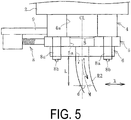
- the rubber extrudate R2 may be curved in an unintended direction (horizontal direction or vertical direction) as illustrated in FIG. 5 even in a case where the rubber extrudate is extruded from the extrusion port 7 with the same shape.
- a center position of the extrusion port 7 in the horizontal direction (width direction) is indicated by a dot-dash line CL
- a center position of the rubber extrudate R2 in the horizontal direction (width direction) is indicated by a dot-dash line M.
- the center position of the extrusion flow path 4a in the horizontal direction coincides with the dot-dash line CL.
- the center position M of the rubber extrudate R2 in the horizontal direction is shifted rightward by a misalignment amount d with respect to the center position CL of the extrusion port 7 in the horizontal direction, and the rubber extrudate R2 is curved rightward (has an amount of curvature d).
- Curving of the rubber extrudate R2 in a specific direction as illustrated in FIG. 5 instead of straight extrusion is expected to be caused by a combination of various factors such as a variation in the rubber physical properties of the unvulcanized rubber R1, extrusion conditions (pressure, temperature, flow velocity, and the like), matching between the cylinder 2 and the screw 3, and the like.
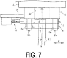
- the control plate 5 positioned as illustrated in FIG. 5 is moved leftward with respect to the head 4 and the die 6 as illustrated in FIG. 6 .
- the extruded unvulcanized rubber R1 has a different pressure and flow rate (has a pressure distribution and flow rate distribution) in the direction orthogonal to the extrusion direction in the extrusion flow path 4a.
- the pressure distribution (fluid flow distribution) changes when the unvulcanized rubber passes through the extrusion flow path 4a and the adjustment flow path 5a and then is extruded from the extrusion port 7.
- a leftward curving force acts on the rubber extrudate R2 to allow the curvature of the rubber extrudate R2 to be adjusted.
- the leftward curving force acting on the rubber extrudate R2 becomes excessively strong, curving the rubber extrudate R2 leftward.
- a position of the control plate 5 is appropriately adjusted to establish a fixed state as illustrated in FIG. 6 .
- the rubber extrudate R2 is extruded.
- the curvature of the rightward curved rubber extrudate R2 is corrected, enabling obtainment of a rubber extrudate R2 formed into a desired straight shape corresponding to the shape of the extrusion port 7.
- a rubber extrudate R2 having a desired shape suppressed from being unintentionally curved can be stably manufactured by controlling the position of the control plate 5 along and between the head 4 and the die 6. Additionally, an embodiment of the present invention eliminates or minimizes a need for excess work performed in the related art to modify the shape of the die 6 by machining or to adjust the extrusion conditions or the like in each case of a variation attributed to the rubber physical properties or the extrusion conditions or the like. This is advantageous in improving the productivity of the rubber extrudate R2.
- the position where the rubber extrudate R2 is extruded (extrusion port 7) can be maintained at a predetermined position. Accordingly, the line for conveying the rubber extrudate R2 to the next step (such as the conveyor device 12) can be set to a given position, so it is not necessary to make a change to the conveying line to accommodate the sliding of the control plate 5 each time. Thus, the layout of the step after the extrusion step is not affected. Additionally, an embodiment of the present invention can be easily applied to an existing rubber extruder since it is sufficient as long as the control plate 5 is interposed between the head 4 and the die 6 and is slidable.
- the sensor 10 at a position located at the distance L forward from the die 6, the sensor 10 successively detects the misalignment amount d of the center position M of rubber extrudate R2 in the horizontal direction with respect to the center position CL of the extrusion port 7 in the horizontal direction.
- the position of the control plate 5 (adjustment flow path 5a) is successively controlled so that the misalignment amount d approaches zero (feedback control is performed).
- the misalignment amount d of the rubber extrudate R is largest at a position located at a distance L of approximately 500 mm, and thus, the sensor 10 detects the misalignment amount d, for example, at a position located at a distance L of from 400 mm to 600 mm.
- the correlation data are input to the control unit 11.
- the actual fluctuation parameters are input into the controller 11, based on these data and the previously input correlation data described above, the control plate 5 is preset to be disposed at a predetermined position, and the rubber extrudate R2 is extruded into a desired shape without having unintended curvature.
- the feedback control described above is then performed.
- the rubber extrudate R2 used for example, as a tire component is manufactured using an embodiment of the present invention
- the rubber extrudate R2 can have the desired shape suppressed from being unintentionally curved.
- manufacturing a tire using the rubber extrudate R2 is advantageous in improving the uniformity of the tire.
- the direction in which the control plate 5 is slid is preferably set in one direction extending in an elongated shape of the extrusion port 7 as in this embodiment (the direction in which the extrusion port 7 extends the longest in the front view). In this way, it is easy to greatly change the pressure distribution (fluid flow distribution) of the unvulcanized rubber R1 when passing through from the extrusion flow path 4a to the adjustment flow path 5a and the extrusion port 7. Thus, the unintended curvature of the rubber extrudate R2 is easily suppressed.
- the control plate 5 is not limited to one, and a plurality of the control plates 5 may be provided. By independently sliding each one of the plurality of control plates 5, the curvature of the rubber extrudate R2 can be more finely adjusted.
- the control plate 5 can be moved not only in the horizontal direction but also in the vertical direction relative to the head 4 and the die 6.
- the moving unit 8 is disposed on an upper side in addition to the left side of the head 4.
- the moving unit 8 disposed on the upper side includes a servo motor and a ball screw rotated and moved in the axial direction by the servo motor, and a tip of the ball screw is connected to an upper surface of the control plate 5.
- the moving unit 8 is connected by a connecting arm 8c to the other moving unit 8 disposed on the left side of the head 4.
- the control plate 5 is sandwiched between the head 4 and the die 6 so as to be able to slide in the horizontal direction and the vertical direction.
- control plate 5 slides the moving unit 8 and the control plate 5 disposed above the control plate 5 along the head 4 and the die 6 in the horizontal direction via the connecting arm 8c.
- the control plate 5 is movable in a freely selectable direction along and between the head 4 and the die 6.
Landscapes
- Engineering & Computer Science (AREA)
- Mechanical Engineering (AREA)
- Manufacturing & Machinery (AREA)
- Extrusion Moulding Of Plastics Or The Like (AREA)
Applications Claiming Priority (2)
| Application Number | Priority Date | Filing Date | Title |
|---|---|---|---|
| JP2017158752A JP6665840B2 (ja) | 2017-08-21 | 2017-08-21 | ゴム押出装置およびゴム押出物の製造方法 |
| PCT/JP2018/021896 WO2019039041A1 (fr) | 2017-08-21 | 2018-06-07 | Dispositif d'extrusion de caoutchouc et procédé de fabrication d'un objet extrudé en caoutchouc |
Publications (3)
| Publication Number | Publication Date |
|---|---|
| EP3674070A1 true EP3674070A1 (fr) | 2020-07-01 |
| EP3674070A4 EP3674070A4 (fr) | 2021-05-26 |
| EP3674070B1 EP3674070B1 (fr) | 2025-06-25 |
Family
ID=65439423
Family Applications (1)
| Application Number | Title | Priority Date | Filing Date |
|---|---|---|---|
| EP18849262.3A Active EP3674070B1 (fr) | 2017-08-21 | 2018-06-07 | Dispositif d'extrusion de caoutchouc et procédé de fabrication d'un objet extrudé en caoutchouc |
Country Status (5)
| Country | Link |
|---|---|
| US (1) | US11534950B2 (fr) |
| EP (1) | EP3674070B1 (fr) |
| JP (1) | JP6665840B2 (fr) |
| CN (1) | CN110753609B (fr) |
| WO (1) | WO2019039041A1 (fr) |
Families Citing this family (1)
| Publication number | Priority date | Publication date | Assignee | Title |
|---|---|---|---|---|
| CN114559590B (zh) * | 2022-02-23 | 2024-03-19 | 高扬 | 一种高硅氧模压系统 |
Family Cites Families (20)
| Publication number | Priority date | Publication date | Assignee | Title |
|---|---|---|---|---|
| JPS5020593B1 (fr) * | 1970-12-23 | 1975-07-16 | ||
| US3830610A (en) | 1970-12-23 | 1974-08-20 | Bridgestone Tire Co Ltd | Apparatus for forming rubber products such as a tread rubber by extrusion |
| JPS5020593A (fr) | 1973-06-25 | 1975-03-04 | ||
| JPS6097824A (ja) * | 1983-11-02 | 1985-05-31 | Bridgestone Corp | 押出機用ヘッド |
| JPH0780436B2 (ja) * | 1988-07-25 | 1995-08-30 | 東海興業株式会社 | ウェザーストリップ、並びにその成形方法及び装置 |
| JPH03143609A (ja) * | 1989-10-31 | 1991-06-19 | Meiji Rubber & Chem Co Ltd | ゴムホース製造用マンドレル並びに該マンドレルを用いる押出装置及び該装置によるゴムホースの製造方法 |
| JP2000289084A (ja) * | 1999-04-12 | 2000-10-17 | Sekisui Chem Co Ltd | 押出成形用金型 |
| JP3834199B2 (ja) | 2000-11-22 | 2006-10-18 | 住友ゴム工業株式会社 | ゴム成形方法およびゴム成形装置 |
| US6663378B2 (en) | 2001-09-27 | 2003-12-16 | Corning Incorporated | Apparatus for correcting bow in a honeycomb extrudate |
| JP2006335017A (ja) * | 2005-06-06 | 2006-12-14 | Bridgestone Corp | 帯状ゴムの押出し方法および装置 |
| JP4822948B2 (ja) * | 2006-06-20 | 2011-11-24 | 株式会社ブリヂストン | ゴム被覆装置及びゴム被覆コードの製造方法 |
| JP2008126560A (ja) | 2006-11-22 | 2008-06-05 | Bridgestone Corp | ゴム成形装置、ゴム部材の製造装置及び製造方法 |
| JP5041930B2 (ja) * | 2007-09-06 | 2012-10-03 | 東洋ゴム工業株式会社 | 円環状ゴム部材の製造方法及びその製造装置 |
| RO126104A2 (ro) * | 2009-09-22 | 2011-03-30 | Inoe 2000-Institutul De Cercetări Pentru Hidraulică Şi Pneumatică | Metodă şi aparat de corelare şi reglare transfer şnur extruder tunel |
| JP2012091340A (ja) | 2010-10-25 | 2012-05-17 | Bridgestone Corp | 押出成形装置及び成形品の製造方法 |
| EP2639041B1 (fr) | 2010-11-11 | 2018-06-27 | Toyo Seikan Group Holdings, Ltd. | Appareil pour corriger la flexion de résine fondue et procédé pour corriger la flexion de résine fondue |
| JP5651504B2 (ja) | 2011-03-08 | 2015-01-14 | 東洋ゴム工業株式会社 | シート状ゴム成形装置及び方法 |
| JP2013216069A (ja) * | 2012-04-12 | 2013-10-24 | Toyo Tire & Rubber Co Ltd | ダイユニット |
| JP6105330B2 (ja) * | 2013-03-07 | 2017-03-29 | 東洋ゴム工業株式会社 | ゴム部材成型装置 |
| JP6520968B2 (ja) | 2017-02-16 | 2019-05-29 | 横浜ゴム株式会社 | ゴム押出装置およびゴム押出物の製造方法 |
-
2017
- 2017-08-21 JP JP2017158752A patent/JP6665840B2/ja active Active
-
2018
- 2018-06-07 CN CN201880040378.0A patent/CN110753609B/zh active Active
- 2018-06-07 EP EP18849262.3A patent/EP3674070B1/fr active Active
- 2018-06-07 WO PCT/JP2018/021896 patent/WO2019039041A1/fr not_active Ceased
- 2018-06-07 US US16/641,147 patent/US11534950B2/en active Active
Also Published As
| Publication number | Publication date |
|---|---|
| JP6665840B2 (ja) | 2020-03-13 |
| US11534950B2 (en) | 2022-12-27 |
| EP3674070B1 (fr) | 2025-06-25 |
| WO2019039041A1 (fr) | 2019-02-28 |
| CN110753609B (zh) | 2022-03-11 |
| JP2019034520A (ja) | 2019-03-07 |
| US20200198207A1 (en) | 2020-06-25 |
| EP3674070A4 (fr) | 2021-05-26 |
| CN110753609A (zh) | 2020-02-04 |
Similar Documents
| Publication | Publication Date | Title |
|---|---|---|
| EP3584056A1 (fr) | Dispositif d'extrusion de caoutchouc et procédé de fabrication d'objet extrudé en caoutchouc | |
| US10821643B2 (en) | System and method for adjusting the land channel length on an extrusion die | |
| US10821644B2 (en) | Rubber extrusion device and method for manufacturing rubber extrudate | |
| US11420375B2 (en) | Extruder and method for extruding cord reinforced tire components | |
| US12434417B2 (en) | Rubber extrusion device and method for manufacturing rubber extrudate | |
| EP3674070A1 (fr) | Dispositif d'extrusion de caoutchouc et procédé de fabrication d'un objet extrudé en caoutchouc | |
| JP7302362B2 (ja) | ゴム押出物の製造装置およびゴム押出物の形状予測方法 | |
| JP2017094493A (ja) | ゴム押出装置 | |
| JP2018130895A (ja) | ゴム押出装置およびゴム押出物の製造方法 | |
| JP2020044774A (ja) | ゴム押出方法および装置 | |
| JP2020196150A (ja) | ゴム押出物の製造装置および方法 |
Legal Events
| Date | Code | Title | Description |
|---|---|---|---|
| STAA | Information on the status of an ep patent application or granted ep patent |
Free format text: STATUS: THE INTERNATIONAL PUBLICATION HAS BEEN MADE |
|
| PUAI | Public reference made under article 153(3) epc to a published international application that has entered the european phase |
Free format text: ORIGINAL CODE: 0009012 |
|
| STAA | Information on the status of an ep patent application or granted ep patent |
Free format text: STATUS: REQUEST FOR EXAMINATION WAS MADE |
|
| 17P | Request for examination filed |
Effective date: 20200117 |
|
| AK | Designated contracting states |
Kind code of ref document: A1 Designated state(s): AL AT BE BG CH CY CZ DE DK EE ES FI FR GB GR HR HU IE IS IT LI LT LU LV MC MK MT NL NO PL PT RO RS SE SI SK SM TR |
|
| AX | Request for extension of the european patent |
Extension state: BA ME |
|
| DAV | Request for validation of the european patent (deleted) | ||
| DAX | Request for extension of the european patent (deleted) | ||
| REG | Reference to a national code |
Ref country code: DE Free format text: PREVIOUS MAIN CLASS: B29K0021000000 Ref legal event code: R079 Ref document number: 602018082994 Country of ref document: DE Ipc: B29C0048310000 |
|
| A4 | Supplementary search report drawn up and despatched |
Effective date: 20210423 |
|
| RIC1 | Information provided on ipc code assigned before grant |
Ipc: B29C 48/31 20190101AFI20210419BHEP Ipc: B29B 7/72 20060101ALI20210419BHEP Ipc: B29B 7/42 20060101ALI20210419BHEP Ipc: B29B 7/74 20060101ALI20210419BHEP Ipc: B29C 48/30 20190101ALI20210419BHEP Ipc: B29C 48/92 20190101ALI20210419BHEP Ipc: B29C 48/07 20190101ALI20210419BHEP Ipc: B29C 48/12 20190101ALI20210419BHEP |
|
| STAA | Information on the status of an ep patent application or granted ep patent |
Free format text: STATUS: EXAMINATION IS IN PROGRESS |
|
| 17Q | First examination report despatched |
Effective date: 20230613 |
|
| RAP3 | Party data changed (applicant data changed or rights of an application transferred) |
Owner name: THE YOKOHAMA RUBBER CO., LTD. |
|
| RAP3 | Party data changed (applicant data changed or rights of an application transferred) |
Owner name: THE YOKOHAMA RUBBER CO., LTD. |
|
| GRAP | Despatch of communication of intention to grant a patent |
Free format text: ORIGINAL CODE: EPIDOSNIGR1 |
|
| STAA | Information on the status of an ep patent application or granted ep patent |
Free format text: STATUS: GRANT OF PATENT IS INTENDED |
|
| INTG | Intention to grant announced |
Effective date: 20250214 |
|
| GRAS | Grant fee paid |
Free format text: ORIGINAL CODE: EPIDOSNIGR3 |
|
| GRAA | (expected) grant |
Free format text: ORIGINAL CODE: 0009210 |
|
| STAA | Information on the status of an ep patent application or granted ep patent |
Free format text: STATUS: THE PATENT HAS BEEN GRANTED |
|
| AK | Designated contracting states |
Kind code of ref document: B1 Designated state(s): AL AT BE BG CH CY CZ DE DK EE ES FI FR GB GR HR HU IE IS IT LI LT LU LV MC MK MT NL NO PL PT RO RS SE SI SK SM TR |
|
| REG | Reference to a national code |
Ref country code: GB Ref legal event code: FG4D |
|
| REG | Reference to a national code |
Ref country code: CH Ref legal event code: EP |
|
| REG | Reference to a national code |
Ref country code: CH Ref legal event code: EP |
|
| P01 | Opt-out of the competence of the unified patent court (upc) registered |
Free format text: CASE NUMBER: APP_26890/2025 Effective date: 20250605 |
|
| REG | Reference to a national code |
Ref country code: IE Ref legal event code: FG4D |
|
| REG | Reference to a national code |
Ref country code: DE Ref legal event code: R096 Ref document number: 602018082994 Country of ref document: DE |
|
| REG | Reference to a national code |
Ref country code: NL Ref legal event code: FP |
|
| PG25 | Lapsed in a contracting state [announced via postgrant information from national office to epo] |
Ref country code: FI Free format text: LAPSE BECAUSE OF FAILURE TO SUBMIT A TRANSLATION OF THE DESCRIPTION OR TO PAY THE FEE WITHIN THE PRESCRIBED TIME-LIMIT Effective date: 20250625 |
|
| REG | Reference to a national code |
Ref country code: LT Ref legal event code: MG9D |
|
| PG25 | Lapsed in a contracting state [announced via postgrant information from national office to epo] |
Ref country code: NO Free format text: LAPSE BECAUSE OF FAILURE TO SUBMIT A TRANSLATION OF THE DESCRIPTION OR TO PAY THE FEE WITHIN THE PRESCRIBED TIME-LIMIT Effective date: 20250925 Ref country code: GR Free format text: LAPSE BECAUSE OF FAILURE TO SUBMIT A TRANSLATION OF THE DESCRIPTION OR TO PAY THE FEE WITHIN THE PRESCRIBED TIME-LIMIT Effective date: 20250926 |
|
| PG25 | Lapsed in a contracting state [announced via postgrant information from national office to epo] |
Ref country code: BG Free format text: LAPSE BECAUSE OF FAILURE TO SUBMIT A TRANSLATION OF THE DESCRIPTION OR TO PAY THE FEE WITHIN THE PRESCRIBED TIME-LIMIT Effective date: 20250625 |
|
| PG25 | Lapsed in a contracting state [announced via postgrant information from national office to epo] |
Ref country code: HR Free format text: LAPSE BECAUSE OF FAILURE TO SUBMIT A TRANSLATION OF THE DESCRIPTION OR TO PAY THE FEE WITHIN THE PRESCRIBED TIME-LIMIT Effective date: 20250625 |
|
| PG25 | Lapsed in a contracting state [announced via postgrant information from national office to epo] |
Ref country code: RS Free format text: LAPSE BECAUSE OF FAILURE TO SUBMIT A TRANSLATION OF THE DESCRIPTION OR TO PAY THE FEE WITHIN THE PRESCRIBED TIME-LIMIT Effective date: 20250925 |
|
| PG25 | Lapsed in a contracting state [announced via postgrant information from national office to epo] |
Ref country code: LV Free format text: LAPSE BECAUSE OF FAILURE TO SUBMIT A TRANSLATION OF THE DESCRIPTION OR TO PAY THE FEE WITHIN THE PRESCRIBED TIME-LIMIT Effective date: 20250625 |
|
| PG25 | Lapsed in a contracting state [announced via postgrant information from national office to epo] |
Ref country code: PT Free format text: LAPSE BECAUSE OF FAILURE TO SUBMIT A TRANSLATION OF THE DESCRIPTION OR TO PAY THE FEE WITHIN THE PRESCRIBED TIME-LIMIT Effective date: 20251027 |
|
| REG | Reference to a national code |
Ref country code: AT Ref legal event code: MK05 Ref document number: 1806037 Country of ref document: AT Kind code of ref document: T Effective date: 20250625 |
|
| PG25 | Lapsed in a contracting state [announced via postgrant information from national office to epo] |
Ref country code: IS Free format text: LAPSE BECAUSE OF FAILURE TO SUBMIT A TRANSLATION OF THE DESCRIPTION OR TO PAY THE FEE WITHIN THE PRESCRIBED TIME-LIMIT Effective date: 20251025 |
|
| PG25 | Lapsed in a contracting state [announced via postgrant information from national office to epo] |
Ref country code: AT Free format text: LAPSE BECAUSE OF FAILURE TO SUBMIT A TRANSLATION OF THE DESCRIPTION OR TO PAY THE FEE WITHIN THE PRESCRIBED TIME-LIMIT Effective date: 20250625 Ref country code: SM Free format text: LAPSE BECAUSE OF FAILURE TO SUBMIT A TRANSLATION OF THE DESCRIPTION OR TO PAY THE FEE WITHIN THE PRESCRIBED TIME-LIMIT Effective date: 20250625 |
|
| PG25 | Lapsed in a contracting state [announced via postgrant information from national office to epo] |
Ref country code: CZ Free format text: LAPSE BECAUSE OF FAILURE TO SUBMIT A TRANSLATION OF THE DESCRIPTION OR TO PAY THE FEE WITHIN THE PRESCRIBED TIME-LIMIT Effective date: 20250625 |
|
| PG25 | Lapsed in a contracting state [announced via postgrant information from national office to epo] |
Ref country code: PL Free format text: LAPSE BECAUSE OF FAILURE TO SUBMIT A TRANSLATION OF THE DESCRIPTION OR TO PAY THE FEE WITHIN THE PRESCRIBED TIME-LIMIT Effective date: 20250625 |
|
| PG25 | Lapsed in a contracting state [announced via postgrant information from national office to epo] |
Ref country code: EE Free format text: LAPSE BECAUSE OF FAILURE TO SUBMIT A TRANSLATION OF THE DESCRIPTION OR TO PAY THE FEE WITHIN THE PRESCRIBED TIME-LIMIT Effective date: 20250625 |
|
| PG25 | Lapsed in a contracting state [announced via postgrant information from national office to epo] |
Ref country code: SK Free format text: LAPSE BECAUSE OF FAILURE TO SUBMIT A TRANSLATION OF THE DESCRIPTION OR TO PAY THE FEE WITHIN THE PRESCRIBED TIME-LIMIT Effective date: 20250625 |
|
| PG25 | Lapsed in a contracting state [announced via postgrant information from national office to epo] |
Ref country code: ES Free format text: LAPSE BECAUSE OF FAILURE TO SUBMIT A TRANSLATION OF THE DESCRIPTION OR TO PAY THE FEE WITHIN THE PRESCRIBED TIME-LIMIT Effective date: 20250625 |
|
| PG25 | Lapsed in a contracting state [announced via postgrant information from national office to epo] |
Ref country code: DK Free format text: LAPSE BECAUSE OF FAILURE TO SUBMIT A TRANSLATION OF THE DESCRIPTION OR TO PAY THE FEE WITHIN THE PRESCRIBED TIME-LIMIT Effective date: 20250625 |
|
| PG25 | Lapsed in a contracting state [announced via postgrant information from national office to epo] |
Ref country code: IT Free format text: LAPSE BECAUSE OF FAILURE TO SUBMIT A TRANSLATION OF THE DESCRIPTION OR TO PAY THE FEE WITHIN THE PRESCRIBED TIME-LIMIT Effective date: 20250625 |
|
| PLBE | No opposition filed within time limit |
Free format text: ORIGINAL CODE: 0009261 |
|
| STAA | Information on the status of an ep patent application or granted ep patent |
Free format text: STATUS: NO OPPOSITION FILED WITHIN TIME LIMIT |