EP3674131A1 - Hilfsbatterieunterbringungsvorrichtung für elektrisches fahrzeug - Google Patents
Hilfsbatterieunterbringungsvorrichtung für elektrisches fahrzeug Download PDFInfo
- Publication number
- EP3674131A1 EP3674131A1 EP19766988.0A EP19766988A EP3674131A1 EP 3674131 A1 EP3674131 A1 EP 3674131A1 EP 19766988 A EP19766988 A EP 19766988A EP 3674131 A1 EP3674131 A1 EP 3674131A1
- Authority
- EP
- European Patent Office
- Prior art keywords
- auxiliary battery
- case body
- storage device
- body cover
- hooking
- Prior art date
- Legal status (The legal status is an assumption and is not a legal conclusion. Google has not performed a legal analysis and makes no representation as to the accuracy of the status listed.)
- Granted
Links
Images




Classifications
-
- B—PERFORMING OPERATIONS; TRANSPORTING
- B60—VEHICLES IN GENERAL
- B60L—PROPULSION OF ELECTRICALLY-PROPELLED VEHICLES; SUPPLYING ELECTRIC POWER FOR AUXILIARY EQUIPMENT OF ELECTRICALLY-PROPELLED VEHICLES; ELECTRODYNAMIC BRAKE SYSTEMS FOR VEHICLES IN GENERAL; MAGNETIC SUSPENSION OR LEVITATION FOR VEHICLES; MONITORING OPERATING VARIABLES OF ELECTRICALLY-PROPELLED VEHICLES; ELECTRIC SAFETY DEVICES FOR ELECTRICALLY-PROPELLED VEHICLES
- B60L58/00—Methods or circuit arrangements for monitoring or controlling batteries or fuel cells, specially adapted for electric vehicles
- B60L58/10—Methods or circuit arrangements for monitoring or controlling batteries or fuel cells, specially adapted for electric vehicles for monitoring or controlling batteries
- B60L58/18—Methods or circuit arrangements for monitoring or controlling batteries or fuel cells, specially adapted for electric vehicles for monitoring or controlling batteries of two or more battery modules
- B60L58/20—Methods or circuit arrangements for monitoring or controlling batteries or fuel cells, specially adapted for electric vehicles for monitoring or controlling batteries of two or more battery modules having different nominal voltages
-
- B—PERFORMING OPERATIONS; TRANSPORTING
- B60—VEHICLES IN GENERAL
- B60L—PROPULSION OF ELECTRICALLY-PROPELLED VEHICLES; SUPPLYING ELECTRIC POWER FOR AUXILIARY EQUIPMENT OF ELECTRICALLY-PROPELLED VEHICLES; ELECTRODYNAMIC BRAKE SYSTEMS FOR VEHICLES IN GENERAL; MAGNETIC SUSPENSION OR LEVITATION FOR VEHICLES; MONITORING OPERATING VARIABLES OF ELECTRICALLY-PROPELLED VEHICLES; ELECTRIC SAFETY DEVICES FOR ELECTRICALLY-PROPELLED VEHICLES
- B60L53/00—Methods of charging batteries, specially adapted for electric vehicles; Charging stations or on-board charging equipment therefor; Exchange of energy storage elements in electric vehicles
- B60L53/80—Exchanging energy storage elements, e.g. removable batteries
-
- B—PERFORMING OPERATIONS; TRANSPORTING
- B60—VEHICLES IN GENERAL
- B60K—ARRANGEMENT OR MOUNTING OF PROPULSION UNITS OR OF TRANSMISSIONS IN VEHICLES; ARRANGEMENT OR MOUNTING OF PLURAL DIVERSE PRIME-MOVERS IN VEHICLES; AUXILIARY DRIVES FOR VEHICLES; INSTRUMENTATION OR DASHBOARDS FOR VEHICLES; ARRANGEMENTS IN CONNECTION WITH COOLING, AIR INTAKE, GAS EXHAUST OR FUEL SUPPLY OF PROPULSION UNITS IN VEHICLES
- B60K1/00—Arrangement or mounting of electrical propulsion units
- B60K1/04—Arrangement or mounting of electrical propulsion units of the electric storage means for propulsion
-
- B—PERFORMING OPERATIONS; TRANSPORTING
- B60—VEHICLES IN GENERAL
- B60L—PROPULSION OF ELECTRICALLY-PROPELLED VEHICLES; SUPPLYING ELECTRIC POWER FOR AUXILIARY EQUIPMENT OF ELECTRICALLY-PROPELLED VEHICLES; ELECTRODYNAMIC BRAKE SYSTEMS FOR VEHICLES IN GENERAL; MAGNETIC SUSPENSION OR LEVITATION FOR VEHICLES; MONITORING OPERATING VARIABLES OF ELECTRICALLY-PROPELLED VEHICLES; ELECTRIC SAFETY DEVICES FOR ELECTRICALLY-PROPELLED VEHICLES
- B60L50/00—Electric propulsion with power supplied within the vehicle
- B60L50/50—Electric propulsion with power supplied within the vehicle using propulsion power supplied by batteries or fuel cells
-
- B—PERFORMING OPERATIONS; TRANSPORTING
- B60—VEHICLES IN GENERAL
- B60L—PROPULSION OF ELECTRICALLY-PROPELLED VEHICLES; SUPPLYING ELECTRIC POWER FOR AUXILIARY EQUIPMENT OF ELECTRICALLY-PROPELLED VEHICLES; ELECTRODYNAMIC BRAKE SYSTEMS FOR VEHICLES IN GENERAL; MAGNETIC SUSPENSION OR LEVITATION FOR VEHICLES; MONITORING OPERATING VARIABLES OF ELECTRICALLY-PROPELLED VEHICLES; ELECTRIC SAFETY DEVICES FOR ELECTRICALLY-PROPELLED VEHICLES
- B60L50/00—Electric propulsion with power supplied within the vehicle
- B60L50/50—Electric propulsion with power supplied within the vehicle using propulsion power supplied by batteries or fuel cells
- B60L50/60—Electric propulsion with power supplied within the vehicle using propulsion power supplied by batteries or fuel cells using power supplied by batteries
-
- B—PERFORMING OPERATIONS; TRANSPORTING
- B60—VEHICLES IN GENERAL
- B60L—PROPULSION OF ELECTRICALLY-PROPELLED VEHICLES; SUPPLYING ELECTRIC POWER FOR AUXILIARY EQUIPMENT OF ELECTRICALLY-PROPELLED VEHICLES; ELECTRODYNAMIC BRAKE SYSTEMS FOR VEHICLES IN GENERAL; MAGNETIC SUSPENSION OR LEVITATION FOR VEHICLES; MONITORING OPERATING VARIABLES OF ELECTRICALLY-PROPELLED VEHICLES; ELECTRIC SAFETY DEVICES FOR ELECTRICALLY-PROPELLED VEHICLES
- B60L50/00—Electric propulsion with power supplied within the vehicle
- B60L50/50—Electric propulsion with power supplied within the vehicle using propulsion power supplied by batteries or fuel cells
- B60L50/60—Electric propulsion with power supplied within the vehicle using propulsion power supplied by batteries or fuel cells using power supplied by batteries
- B60L50/64—Constructional details of batteries specially adapted for electric vehicles
-
- B—PERFORMING OPERATIONS; TRANSPORTING
- B60—VEHICLES IN GENERAL
- B60L—PROPULSION OF ELECTRICALLY-PROPELLED VEHICLES; SUPPLYING ELECTRIC POWER FOR AUXILIARY EQUIPMENT OF ELECTRICALLY-PROPELLED VEHICLES; ELECTRODYNAMIC BRAKE SYSTEMS FOR VEHICLES IN GENERAL; MAGNETIC SUSPENSION OR LEVITATION FOR VEHICLES; MONITORING OPERATING VARIABLES OF ELECTRICALLY-PROPELLED VEHICLES; ELECTRIC SAFETY DEVICES FOR ELECTRICALLY-PROPELLED VEHICLES
- B60L50/00—Electric propulsion with power supplied within the vehicle
- B60L50/50—Electric propulsion with power supplied within the vehicle using propulsion power supplied by batteries or fuel cells
- B60L50/60—Electric propulsion with power supplied within the vehicle using propulsion power supplied by batteries or fuel cells using power supplied by batteries
- B60L50/66—Arrangements of batteries
-
- B—PERFORMING OPERATIONS; TRANSPORTING
- B60—VEHICLES IN GENERAL
- B60L—PROPULSION OF ELECTRICALLY-PROPELLED VEHICLES; SUPPLYING ELECTRIC POWER FOR AUXILIARY EQUIPMENT OF ELECTRICALLY-PROPELLED VEHICLES; ELECTRODYNAMIC BRAKE SYSTEMS FOR VEHICLES IN GENERAL; MAGNETIC SUSPENSION OR LEVITATION FOR VEHICLES; MONITORING OPERATING VARIABLES OF ELECTRICALLY-PROPELLED VEHICLES; ELECTRIC SAFETY DEVICES FOR ELECTRICALLY-PROPELLED VEHICLES
- B60L53/00—Methods of charging batteries, specially adapted for electric vehicles; Charging stations or on-board charging equipment therefor; Exchange of energy storage elements in electric vehicles
- B60L53/10—Methods of charging batteries, specially adapted for electric vehicles; Charging stations or on-board charging equipment therefor; Exchange of energy storage elements in electric vehicles characterised by the energy transfer between the charging station and the vehicle
- B60L53/14—Conductive energy transfer
-
- B—PERFORMING OPERATIONS; TRANSPORTING
- B60—VEHICLES IN GENERAL
- B60L—PROPULSION OF ELECTRICALLY-PROPELLED VEHICLES; SUPPLYING ELECTRIC POWER FOR AUXILIARY EQUIPMENT OF ELECTRICALLY-PROPELLED VEHICLES; ELECTRODYNAMIC BRAKE SYSTEMS FOR VEHICLES IN GENERAL; MAGNETIC SUSPENSION OR LEVITATION FOR VEHICLES; MONITORING OPERATING VARIABLES OF ELECTRICALLY-PROPELLED VEHICLES; ELECTRIC SAFETY DEVICES FOR ELECTRICALLY-PROPELLED VEHICLES
- B60L53/00—Methods of charging batteries, specially adapted for electric vehicles; Charging stations or on-board charging equipment therefor; Exchange of energy storage elements in electric vehicles
- B60L53/10—Methods of charging batteries, specially adapted for electric vehicles; Charging stations or on-board charging equipment therefor; Exchange of energy storage elements in electric vehicles characterised by the energy transfer between the charging station and the vehicle
- B60L53/14—Conductive energy transfer
- B60L53/18—Cables specially adapted for charging electric vehicles
-
- B—PERFORMING OPERATIONS; TRANSPORTING
- B60—VEHICLES IN GENERAL
- B60L—PROPULSION OF ELECTRICALLY-PROPELLED VEHICLES; SUPPLYING ELECTRIC POWER FOR AUXILIARY EQUIPMENT OF ELECTRICALLY-PROPELLED VEHICLES; ELECTRODYNAMIC BRAKE SYSTEMS FOR VEHICLES IN GENERAL; MAGNETIC SUSPENSION OR LEVITATION FOR VEHICLES; MONITORING OPERATING VARIABLES OF ELECTRICALLY-PROPELLED VEHICLES; ELECTRIC SAFETY DEVICES FOR ELECTRICALLY-PROPELLED VEHICLES
- B60L58/00—Methods or circuit arrangements for monitoring or controlling batteries or fuel cells, specially adapted for electric vehicles
- B60L58/10—Methods or circuit arrangements for monitoring or controlling batteries or fuel cells, specially adapted for electric vehicles for monitoring or controlling batteries
- B60L58/12—Methods or circuit arrangements for monitoring or controlling batteries or fuel cells, specially adapted for electric vehicles for monitoring or controlling batteries responding to state of charge [SoC]
-
- B—PERFORMING OPERATIONS; TRANSPORTING
- B60—VEHICLES IN GENERAL
- B60L—PROPULSION OF ELECTRICALLY-PROPELLED VEHICLES; SUPPLYING ELECTRIC POWER FOR AUXILIARY EQUIPMENT OF ELECTRICALLY-PROPELLED VEHICLES; ELECTRODYNAMIC BRAKE SYSTEMS FOR VEHICLES IN GENERAL; MAGNETIC SUSPENSION OR LEVITATION FOR VEHICLES; MONITORING OPERATING VARIABLES OF ELECTRICALLY-PROPELLED VEHICLES; ELECTRIC SAFETY DEVICES FOR ELECTRICALLY-PROPELLED VEHICLES
- B60L58/00—Methods or circuit arrangements for monitoring or controlling batteries or fuel cells, specially adapted for electric vehicles
- B60L58/10—Methods or circuit arrangements for monitoring or controlling batteries or fuel cells, specially adapted for electric vehicles for monitoring or controlling batteries
- B60L58/18—Methods or circuit arrangements for monitoring or controlling batteries or fuel cells, specially adapted for electric vehicles for monitoring or controlling batteries of two or more battery modules
-
- B—PERFORMING OPERATIONS; TRANSPORTING
- B60—VEHICLES IN GENERAL
- B60L—PROPULSION OF ELECTRICALLY-PROPELLED VEHICLES; SUPPLYING ELECTRIC POWER FOR AUXILIARY EQUIPMENT OF ELECTRICALLY-PROPELLED VEHICLES; ELECTRODYNAMIC BRAKE SYSTEMS FOR VEHICLES IN GENERAL; MAGNETIC SUSPENSION OR LEVITATION FOR VEHICLES; MONITORING OPERATING VARIABLES OF ELECTRICALLY-PROPELLED VEHICLES; ELECTRIC SAFETY DEVICES FOR ELECTRICALLY-PROPELLED VEHICLES
- B60L58/00—Methods or circuit arrangements for monitoring or controlling batteries or fuel cells, specially adapted for electric vehicles
- B60L58/10—Methods or circuit arrangements for monitoring or controlling batteries or fuel cells, specially adapted for electric vehicles for monitoring or controlling batteries
- B60L58/18—Methods or circuit arrangements for monitoring or controlling batteries or fuel cells, specially adapted for electric vehicles for monitoring or controlling batteries of two or more battery modules
- B60L58/22—Balancing the charge of battery modules
-
- H—ELECTRICITY
- H01—ELECTRIC ELEMENTS
- H01M—PROCESSES OR MEANS, e.g. BATTERIES, FOR THE DIRECT CONVERSION OF CHEMICAL ENERGY INTO ELECTRICAL ENERGY
- H01M10/00—Secondary cells; Manufacture thereof
- H01M10/42—Methods or arrangements for servicing or maintenance of secondary cells or secondary half-cells
-
- H—ELECTRICITY
- H01—ELECTRIC ELEMENTS
- H01M—PROCESSES OR MEANS, e.g. BATTERIES, FOR THE DIRECT CONVERSION OF CHEMICAL ENERGY INTO ELECTRICAL ENERGY
- H01M10/00—Secondary cells; Manufacture thereof
- H01M10/42—Methods or arrangements for servicing or maintenance of secondary cells or secondary half-cells
- H01M10/4207—Methods or arrangements for servicing or maintenance of secondary cells or secondary half-cells for several batteries or cells simultaneously or sequentially
-
- H—ELECTRICITY
- H01—ELECTRIC ELEMENTS
- H01M—PROCESSES OR MEANS, e.g. BATTERIES, FOR THE DIRECT CONVERSION OF CHEMICAL ENERGY INTO ELECTRICAL ENERGY
- H01M10/00—Secondary cells; Manufacture thereof
- H01M10/42—Methods or arrangements for servicing or maintenance of secondary cells or secondary half-cells
- H01M10/425—Structural combination with electronic components, e.g. electronic circuits integrated to the outside of the casing
-
- H—ELECTRICITY
- H01—ELECTRIC ELEMENTS
- H01M—PROCESSES OR MEANS, e.g. BATTERIES, FOR THE DIRECT CONVERSION OF CHEMICAL ENERGY INTO ELECTRICAL ENERGY
- H01M16/00—Structural combinations of different types of electrochemical generators
- H01M16/003—Structural combinations of different types of electrochemical generators of fuel cells with other electrochemical devices, e.g. capacitors, electrolysers
- H01M16/006—Structural combinations of different types of electrochemical generators of fuel cells with other electrochemical devices, e.g. capacitors, electrolysers of fuel cells with rechargeable batteries
-
- H—ELECTRICITY
- H01—ELECTRIC ELEMENTS
- H01M—PROCESSES OR MEANS, e.g. BATTERIES, FOR THE DIRECT CONVERSION OF CHEMICAL ENERGY INTO ELECTRICAL ENERGY
- H01M50/00—Constructional details or processes of manufacture of the non-active parts of electrochemical cells other than fuel cells, e.g. hybrid cells
- H01M50/20—Mountings; Secondary casings or frames; Racks, modules or packs; Suspension devices; Shock absorbers; Transport or carrying devices; Holders
- H01M50/262—Mountings; Secondary casings or frames; Racks, modules or packs; Suspension devices; Shock absorbers; Transport or carrying devices; Holders with fastening means, e.g. locks
-
- H—ELECTRICITY
- H01—ELECTRIC ELEMENTS
- H01M—PROCESSES OR MEANS, e.g. BATTERIES, FOR THE DIRECT CONVERSION OF CHEMICAL ENERGY INTO ELECTRICAL ENERGY
- H01M50/00—Constructional details or processes of manufacture of the non-active parts of electrochemical cells other than fuel cells, e.g. hybrid cells
- H01M50/20—Mountings; Secondary casings or frames; Racks, modules or packs; Suspension devices; Shock absorbers; Transport or carrying devices; Holders
- H01M50/271—Lids or covers for the racks or secondary casings
-
- H—ELECTRICITY
- H01—ELECTRIC ELEMENTS
- H01M—PROCESSES OR MEANS, e.g. BATTERIES, FOR THE DIRECT CONVERSION OF CHEMICAL ENERGY INTO ELECTRICAL ENERGY
- H01M50/00—Constructional details or processes of manufacture of the non-active parts of electrochemical cells other than fuel cells, e.g. hybrid cells
- H01M50/20—Mountings; Secondary casings or frames; Racks, modules or packs; Suspension devices; Shock absorbers; Transport or carrying devices; Holders
- H01M50/296—Mountings; Secondary casings or frames; Racks, modules or packs; Suspension devices; Shock absorbers; Transport or carrying devices; Holders characterised by terminals of battery packs
-
- H—ELECTRICITY
- H01—ELECTRIC ELEMENTS
- H01M—PROCESSES OR MEANS, e.g. BATTERIES, FOR THE DIRECT CONVERSION OF CHEMICAL ENERGY INTO ELECTRICAL ENERGY
- H01M50/00—Constructional details or processes of manufacture of the non-active parts of electrochemical cells other than fuel cells, e.g. hybrid cells
- H01M50/20—Mountings; Secondary casings or frames; Racks, modules or packs; Suspension devices; Shock absorbers; Transport or carrying devices; Holders
- H01M50/298—Mountings; Secondary casings or frames; Racks, modules or packs; Suspension devices; Shock absorbers; Transport or carrying devices; Holders characterised by the wiring of battery packs
-
- H—ELECTRICITY
- H02—GENERATION; CONVERSION OR DISTRIBUTION OF ELECTRIC POWER
- H02J—ELECTRIC POWER NETWORKS; CIRCUIT ARRANGEMENTS OR SYSTEMS FOR SUPPLYING OR DISTRIBUTING ELECTRIC POWER; SYSTEMS FOR STORING ELECTRIC ENERGY
- H02J7/00—Circuit arrangements for charging or discharging batteries or for supplying loads from batteries
- H02J7/34—Parallel operation in networks using both storage and other DC sources, e.g. providing buffering
- H02J7/342—The other DC source being a battery actively interacting with the first one, i.e. battery to battery charging
-
- H—ELECTRICITY
- H02—GENERATION; CONVERSION OR DISTRIBUTION OF ELECTRIC POWER
- H02J—ELECTRIC POWER NETWORKS; CIRCUIT ARRANGEMENTS OR SYSTEMS FOR SUPPLYING OR DISTRIBUTING ELECTRIC POWER; SYSTEMS FOR STORING ELECTRIC ENERGY
- H02J7/00—Circuit arrangements for charging or discharging batteries or for supplying loads from batteries
- H02J7/50—Circuit arrangements for charging or discharging batteries or for supplying loads from batteries acting upon multiple batteries simultaneously or sequentially
- H02J7/52—Circuit arrangements for charging or discharging batteries or for supplying loads from batteries acting upon multiple batteries simultaneously or sequentially for charge balancing, e.g. equalisation of charge between batteries
-
- B—PERFORMING OPERATIONS; TRANSPORTING
- B60—VEHICLES IN GENERAL
- B60Y—INDEXING SCHEME RELATING TO ASPECTS CROSS-CUTTING VEHICLE TECHNOLOGY
- B60Y2200/00—Type of vehicle
- B60Y2200/90—Vehicles comprising electric prime movers
- B60Y2200/91—Electric vehicles
-
- H—ELECTRICITY
- H01—ELECTRIC ELEMENTS
- H01M—PROCESSES OR MEANS, e.g. BATTERIES, FOR THE DIRECT CONVERSION OF CHEMICAL ENERGY INTO ELECTRICAL ENERGY
- H01M2220/00—Batteries for particular applications
- H01M2220/20—Batteries in motive systems, e.g. vehicle, ship, plane
-
- Y—GENERAL TAGGING OF NEW TECHNOLOGICAL DEVELOPMENTS; GENERAL TAGGING OF CROSS-SECTIONAL TECHNOLOGIES SPANNING OVER SEVERAL SECTIONS OF THE IPC; TECHNICAL SUBJECTS COVERED BY FORMER USPC CROSS-REFERENCE ART COLLECTIONS [XRACs] AND DIGESTS
- Y02—TECHNOLOGIES OR APPLICATIONS FOR MITIGATION OR ADAPTATION AGAINST CLIMATE CHANGE
- Y02E—REDUCTION OF GREENHOUSE GAS [GHG] EMISSIONS, RELATED TO ENERGY GENERATION, TRANSMISSION OR DISTRIBUTION
- Y02E60/00—Enabling technologies; Technologies with a potential or indirect contribution to GHG emissions mitigation
- Y02E60/30—Hydrogen technology
- Y02E60/50—Fuel cells
-
- Y—GENERAL TAGGING OF NEW TECHNOLOGICAL DEVELOPMENTS; GENERAL TAGGING OF CROSS-SECTIONAL TECHNOLOGIES SPANNING OVER SEVERAL SECTIONS OF THE IPC; TECHNICAL SUBJECTS COVERED BY FORMER USPC CROSS-REFERENCE ART COLLECTIONS [XRACs] AND DIGESTS
- Y02—TECHNOLOGIES OR APPLICATIONS FOR MITIGATION OR ADAPTATION AGAINST CLIMATE CHANGE
- Y02T—CLIMATE CHANGE MITIGATION TECHNOLOGIES RELATED TO TRANSPORTATION
- Y02T10/00—Road transport of goods or passengers
- Y02T10/60—Other road transportation technologies with climate change mitigation effect
- Y02T10/7072—Electromobility specific charging systems or methods for batteries, ultracapacitors, supercapacitors or double-layer capacitors
-
- Y—GENERAL TAGGING OF NEW TECHNOLOGICAL DEVELOPMENTS; GENERAL TAGGING OF CROSS-SECTIONAL TECHNOLOGIES SPANNING OVER SEVERAL SECTIONS OF THE IPC; TECHNICAL SUBJECTS COVERED BY FORMER USPC CROSS-REFERENCE ART COLLECTIONS [XRACs] AND DIGESTS
- Y02—TECHNOLOGIES OR APPLICATIONS FOR MITIGATION OR ADAPTATION AGAINST CLIMATE CHANGE
- Y02T—CLIMATE CHANGE MITIGATION TECHNOLOGIES RELATED TO TRANSPORTATION
- Y02T90/00—Enabling technologies or technologies with a potential or indirect contribution to GHG emissions mitigation
- Y02T90/10—Technologies relating to charging of electric vehicles
- Y02T90/14—Plug-in electric vehicles
Definitions
- the present disclosure relates to an auxiliary battery storage device, and more particularly, to a storage device capable of exchanging an auxiliary battery safety and conveniently.
- a battery module mounted on a high-output product such as an electric vehicle includes a plurality of cells connected in series or in parallel, since a high voltage is to be supplied to a load.
- the state of charges (SOCs) of the cells become different from each other due to the difference in the self-discharge rate of the cells.
- the buck method has a problem that energy is wasted during the cell balancing process, and the boost method has a disadvantage that the circuit design becomes complicated because a charge circuit must be connected to every cell.
- the auxiliary battery is connected to cells having relatively high SOC, and the electric energy stored in the cells are discharged to charge the auxiliary battery. If so, the buck-type cell balancing is achieved, and energy is not wasted in this process.
- the auxiliary battery is charged to some extent, the auxiliary battery is connected to cells having relatively low SOC to discharge the electric energy stored in the auxiliary battery so that the cells having relatively low SOC are charged. Then, unlike the existing boost method, it is possible to realize cell balancing by recycling the energy stored in the auxiliary battery even though there is no separate current source for generating the charging current.
- the cell balancing method using the auxiliary battery has a problem that the auxiliary battery is rapidly degraded because the auxiliary battery is frequently charged and discharged. If the battery is degraded, internal resistance is increased to generate heat, and negative reaction occurs inside the battery to generate gas. Thus, if the auxiliary battery is degraded, safety of the cell balancing is deteriorated.
- the auxiliary battery should be exchanged periodically.
- the auxiliary battery since the auxiliary battery is installed in the exterior of the battery along with a plurality of cells, it is troublesome to disassemble the exterior of the battery in order to exchange the auxiliary battery.
- the battery since the battery is mounted below a body frame, lifting equipment and maintenance experts are needed to lift the electric vehicle and exchange the auxiliary battery.
- the auxiliary battery is moved to a bonnet or a rear trunk of the vehicle, and the auxiliary battery and the main battery module are electrically connected to each other using a power cable.
- auxiliary battery is installed in a space directly accessible to a driver, such as a car bonnet or a rear trunk, it is still not easy for an unskilled person to exchange the auxiliary battery due to space constraints, resultant complicated wiring and safety reasons.
- the present disclosure is designed to solve the problems of the related art, and therefore the present disclosure is directed to providing an auxiliary battery storage device, which allows an auxiliary battery to be electrically connected to a main battery while the auxiliary battery is being stored so that the auxiliary battery may be easily exchanged even by an unskilled person.
- an auxiliary battery storage device for storing an auxiliary battery that is used for performing cell balancing to a main battery adopted in an electric vehicle or supplying power to the main battery having low state of charge (SOC), the auxiliary battery storage device comprising: a case body formed in a box shape with an open top portion to have an inner space in which the auxiliary battery is stored; a case body cover coupled to the case body to open or close the open top portion of the case body; a terminal connection member fixed to an inner surface of the case body cover to contact a power terminal of the auxiliary battery when the top portion of the case body is closed by the case body cover; and a power cable configured to extend from the terminal connection member to the main battery.
- the terminal connection member may include a protruding pin provided to be connected to or disconnected from the power terminal of the auxiliary battery in a receptacle manner.
- the auxiliary battery storage device may further comprise a fastening member configured to fix the case body cover to the auxiliary battery, wherein the fastening member may be at least one bolt that has a gripping ring at a head portion thereof and is integrally connected to the case body cover and the auxiliary battery.
- the case body may include a cable passage formed in at least one side plate thereof so that the power cable passes therethrough.
- the case body cover may be hinged to one side plate of the case body, the cable passage may have two openings forming an entrance and an exit thereof so that the two openings are located at a top end and an outer side of the side plate, and the top end of the side plate at which the opening is located may be depressed down compared to other regions.
- the case body may have hooking grooves formed in side plates thereof facing each other, and the case body cover may have hooking protrusions engaged with the hooking grooves so that the case body and the case body cover are coupled to each other, and the hooking protrusions may be respectively moved by an electromagnetic force to be engaged with or disengaged from the hooking grooves.
- the case body cover may include an electromagnet disposed at a position spaced apart from the hooking protrusion by a predetermined distance to pull the hooking protrusion by an electromagnetic force to be disengaged from the hooking groove; and a spring configured to elastically bias the hooking protrusion toward the hooking groove so that the hooking protrusion is engaged with the hooking groove.
- the hooking protrusion may include a jaw engaged with the hooking groove; and a stopper configured to extend opposite to the jaw to support an upper surface of the auxiliary battery downward.
- the auxiliary battery storage device may further comprise a lifting unit configured to move the auxiliary battery up and down to a preset height in the case body.
- the lifting unit may include a support plate formed with a table shape to support the auxiliary battery inside the case body; a lifting rod configured to vertically pass through a lower plate of the case body and be connected to the support plate; and a driving motor configured to move the lifting rod up and down.
- an electric vehicle comprising the auxiliary battery storage device described above.
- the auxiliary battery and the main battery may be electrically connected only by inserting the auxiliary battery into the case body and covering the case body by the case body cover, the auxiliary battery may be safely and easily exchanged even by an unskilled person.
- the electrical connection between the connector on the case body cover and the power terminal of the auxiliary battery may be stably maintained even when external shocks or vibrations are applied thereto.
- An auxiliary battery 3 mentioned in this specification may mean a battery used for performing cell balancing to a main battery 2 adopted in an electric vehicle 1 or supplying power to the main battery 2 with a low state of charge (SOC).
- SOC state of charge
- the auxiliary battery 3 discharges the electric energy stored in cells having relatively high SOC to equalize the SOC with the other cells, and the discharged electric energy is used to charge the auxiliary battery 3.
- the auxiliary battery 3 is connected to cells having relatively low SOC to discharge the electric energy stored in the auxiliary battery 3 so that the cells having relatively low SOC are charged to equalize the SOC with the other cells.
- the auxiliary battery 3 may be installed at a location at which the auxiliary battery 3 may be easily maintained and easily exchanged at emergency separately from the main battery 2.
- An auxiliary battery storage device 5 may be understood as an article used to accommodate and store the auxiliary battery 3.
- the auxiliary battery storage device 5 according to the present disclosure may also be used to accommodate a fuel cell (serving for starting a general vehicle or supplying power to various devices) having a similar function and structure to the auxiliary battery 3.
- the main battery 2 may be coupled to a lower frame of the vehicle, and the auxiliary battery 3 may be mounted to a bonnet or a rear trunk of the vehicle.
- the main battery 2 and the auxiliary battery 3 may be electrically connected through a power cable 40.
- the auxiliary battery storage device 5 is a device for casing the auxiliary battery 3, and when the auxiliary battery 3 is exchanged, a new auxiliary battery 3 may be accommodated in the auxiliary battery storage device 5 and simultaneously connected to the auxiliary battery storage device 5.
- auxiliary battery storage device 5 As will be described later in detail, if the auxiliary battery storage device 5 according to the present disclosure is used, a new auxiliary battery 3 is electrically connected to the main battery 2 only by mounting the new auxiliary battery 3 to the storage device. Thus, the auxiliary battery 3 may be exchanged safety and easily even by an unskilled person.
- the auxiliary battery storage device 5 will be described in detail with reference to FIGS. 2 to 4 .
- FIG. 2 is a perspective view schematically showing the auxiliary battery storage device according to an embodiment of the present disclosure
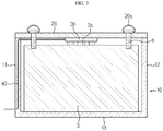
- FIG. 3 is a cross-sectioned view schematically showing the auxiliary battery storage device according to an embodiment of the present disclosure
- FIG. 4 is an enlarged view showing a power cable and an inlet of a cable passage of FIG. 2 .
- the auxiliary battery storage device 5 includes a case body 10, a case body cover 20, a terminal connection member 30, and a power cable 40.
- the auxiliary battery storage device 5 may be disposed at, for example, a bonnet or a rear trunk.
- the case body 10 may include a lower plate 13 and four side plates 11, 12 forming walls, and may be formed in a box shape with an open top portion.
- the auxiliary battery 3 may be placed in the inner space formed inside the case body 10. At this time, a power terminal 3a of the auxiliary battery is provided to face the open top portion of the case body 10.
- the lower plate 13 of the case body 10 may be fixed horizontally to a bottom surface of the bonnet or the trunk by a component such as a bracket.
- the side plates 11, 12 of the case body 10 define the inner space of the case body 10.
- the side plates 11, 12 may be formed at least higher than the height of the auxiliary battery 3 so that the auxiliary battery 3 is fully inserted into the inner space of the case body 10.
- the auxiliary battery 3 accommodated in the case body 10 may be protected from external impact by the side plates 11, 12.
- the side plates 11, 12 may be used as a wiring path of the power cable 40, explained later.
- the case body 10 is designed to have a rectangular parallelepiped box shape, but the shape of the case body 10 may be changed depending on the volume or the installation place of the auxiliary battery 3.
- the case body cover 20 is a component that closes the open top portion of the case body 10.
- the case body cover 20 according to this embodiment has a plate shape sized corresponding to the area of the open top portion of the case body 10 and is provided to be hinged to the case body 10.
- the case body cover 20 is rotatably coupled to any one side plate 11 of the side plates 11, 12 of the case body 10 by a hinge to open and close the top portion of the case body 10. That is, the top portion of the case body 10 may be opened or closed by rotating the case body cover 20.
- a terminal connection member 30 serving as is a component electrically connected to the power terminal 3a of the auxiliary battery is fixedly coupled to an inner surface of the case body cover 20.
- the terminal connection member 30 may be configured as a male connector having protruding pins 31, and the power terminal 3a of the auxiliary battery may be configured as a female connector having a socket that may be coupled with the protruding pins 31 in a receptacle manner.
- the terminal connection member 30 may be disposed at a center of the inner surface of the case body cover 20 so that the terminal connection member 30 is connected to the power terminal 3a of the auxiliary battery when the top portion of the case body 10 is completely closed by the case body cover 20.
- the protruding pins 31 of the terminal connection member 30 are connected to the power terminal 3a of the auxiliary battery, and if the case body cover 20 is opened, the protruding pins 31 of the terminal connection member 30 are disconnected from the power terminal 3a of the auxiliary battery.
- the position of the terminal connection member 30 may be changed corresponding to the position of the power terminal 3a of the auxiliary device.
- the terminal connection member 30 may be located at any position on the inner surface of the case body cover 20 as long as the terminal connection member 30 contacts the power terminal 3a of the auxiliary battery when the top portion of the case body 10 is closed by the case body cover 20.
- the main and the female connectors may be connected in any way such as a point contact method other than the receptacle method, as long as the main and the female connectors can be contacted with each other.
- the auxiliary battery storage device may further include a fastening member 20a that fixes the case body cover 20 and the auxiliary battery 3 in a state where the top portion of the case body 10 is closed by the case body cover 20.
- a bolt may be employed having a gripping ring formed in a head portion thereof.
- a bolt may be inserted into bolt fastening holes H, which are provided in corner regions of the case body cover 20 and the auxiliary battery 3 in one-to-one relationship, to integrally fix the case body cover 20 and the auxiliary battery 3.
- a worker may grip the gripping ring and turn the bolt, so that the bolt may be tightened without using a tool such as a spanner.
- the power cable 40 is a component for electrically connecting the auxiliary battery 3 and the main battery 2 and allows the auxiliary battery 3 to be separated from the main battery 2 and placed in a trunk space that is easily accessible to the driver.
- the power cable 40 is connected to the main battery 2 having one side connected to the terminal connection member 30 and the other side installed to the body frame. Thus, if the top portion of the case body 10 is closed by the case body cover 20, the power of the auxiliary battery 3 may be supplied to the main battery 2.
- the power cable 40 may extend from the terminal connection member 30 through the side plate 11 of the case body 10 to the outside of the case body 10 toward the main battery 2.
- the side plate 11 of the case body has a hollow structure in which a cable passage is provided.
- Two openings forming an entrance and an exit of the cable passage are respectively located at a top end and an outer side of the side plate 11 to which the case body cover 20 are hinged, and the cable passage may be formed to extend straightly downward from an inlet 14 located at the top end of the side plate 11 approximately to an outlet adjacent to a bottom end of the side plate 11.
- the top portion of the side plate 11 where the inlet 14 of the cable passage is located may be depressed compared to regions other than the top portion.
- the top portion of the side plate 11 corresponding to the inlet 14 of the cable passage may be concavely recessed relative to other portions.
- the cable passage is provided in the side plate 11 of the case body 10 as described above, the interference between the power cable 40 and the auxiliary battery 3 in the case body 10 may be minimized. Also, when the top portion of the case body 10 is closed by the case body cover 20, the power cable 40 may not interfere with the case body cover 20 at all.
- the auxiliary battery storage device 5 If the auxiliary battery storage device 5 according to the present disclosure having the above structure and operation is used, it is possible to protect the auxiliary battery 3 from external impact. Moreover, since the power terminal 3a of the auxiliary battery is connected to or disconnected from the power cable 40 by putting the auxiliary battery 3 into the case body 10 and opening or closing the case body 10 by the case body cover 20, it is not necessary to carry out the wiring work in a state of wearing safety equipment, different from the conventional art. Thus, the auxiliary battery 3 may be safely and easily exchanged even by an unskilled person.
- auxiliary battery storage device 5 according to another embodiment of the present disclosure will be described.
- the same reference numerals as those in the former embodiment denote the same components and will not be described in detail again, and features different from the former embodiment will be described in detail.
- FIGS. 5 and 6 are cross-sectioned views showing an auxiliary battery storage device 5 according to another embodiment of the present disclosure to illustrate the process of mounting or separating the case body cover 20 and loading or unloading the auxiliary battery 3
- FIGS. 7 and 8 are diagrams for illustrating the states before and after a hooking protrusion 21 of the case body cover 20 is operated according to another embodiment of the present disclosure.
- the auxiliary battery storage device 5 is configured to allow the worker to exchange the auxiliary battery 3 more conveniently than the former embodiment.
- the worker when fixing the case body cover 20 and the auxiliary battery 3, the worker must directly fasten the bolt, and if there is no tool such as a spanner, the fastening force for the bolt may not be sufficient.
- the case body cover 20 and the auxiliary battery 3 may be fixed and separated by turning on/off an opening/closing button, thereby eliminating the inconvenience of the former embodiment.
- hooking grooves 16 are provided at the two side plates 11, 12 of the case body 10, and hooking protrusions 21 engaging with the hooking grooves 16 are provided on the case body cover 20.
- the case body cover 20 may close or open the case body 10 as the hooking protrusions 21 and the hooking grooves 16 are engaged or disengaged.
- the hooking protrusion 21 may be configured to be horizontally movable by an electromagnetic force so as to be inserted into or released from the hooking groove 16.
- the case body cover 20 of this embodiment includes an electromagnet 22 and a pair of springs 23 therein.
- the hooking protrusion 21 may be mounted vertically to the case body cover 20 in a state where the top end of the hooking protrusion 21 is connected to the pair of springs 23.
- the pair of springs 23 may be spaced apart from each other by a predetermined distance in the width direction of the hooking protrusion, and the electromagnet may be disposed in the middle between the springs 23 while keeping a constant gap from the hooking protrusion 21.
- Four assemblies in which the electromagnet 22, the pair of springs 23 and the hooking protrusion 21 are combined may be assembled at four corners of the case body cover 20, respectively.
- the operating mechanism of the hooking protrusion 21 will be briefly described.
- the electromagnet 22 is a metal rod around which a coil is wound. If an electric current flows through the coil, an electromagnetic force is generated. Thus, as shown in FIG. 7 , if a switch is turned on so that a current flows through the electromagnet 22, the hooking protrusion 21 is pulled toward the electromagnet 22 and released from the hooking groove 16.
- at least the top end of the hooking protrusion 21 is made of metal.
- the hooking protrusion 21 may be elastically biased toward the hooking groove 16 by the elastic force of the spring 23 to engage with the hooking groove 16.
- the operation button may be disposed at an outer surface of the case cover 20, or the operation button may also be configured to turn the switch on/off wirelessly.
- the hooking protrusion 21 may further include a top end mounted to the case body cover 20 in a state of being connected to the spring 23, and a jaw 21a and a stopper 21b disposed below the top end.
- the jaw 21a is a portion that is substantially engaged with the hooking groove 16 in the hooking protrusion 21. That is, depending on the location of the jaw 21a with respect to the hooking groove 16 by the electromagnet 22 and the spring 23, it is determined whether the case body cover 20 and the case body 10 are coupled or separated.
- the stopper 21b is a portion that extends horizontally opposite to the jaw 21a.
- the stopper 21b may extend at least to a position at which the stopper may contact the upper surface of the auxiliary battery 3. As shown in FIG. 5 , when the top portion of the case body 10 is closed by the case body cover 20, the stopper 21b supports the upper surface of the auxiliary battery 3 downward.
- the gap between the case body cover 20 and the auxiliary battery 3 may be kept constant.
- the auxiliary battery storage device 5 may further include a lifting unit 50 for supporting a lower portion of the auxiliary battery 3 and moving the auxiliary battery 3 up and down to a preset height in the inner space of the case body 10.
- the lifting unit 50 relieves the effort of the worker when inserting or removing the auxiliary battery 3 into/from the case body 10.
- the lifting unit 50 is very useful.
- the lifting unit 50 may include a support plate 51 having a table shape and disposed to contact the lower surface of the auxiliary battery 3, a lifting rod 52 vertically connected to the support plate 51, and a driving motor 53 for moving the lifting rod 52 up and down.
- the support plate 51 is formed in a plate shape sized corresponding to the lower surface of the auxiliary battery 3a and is provided to have a substantially table shape to stably support the auxiliary battery 3.
- a rubber pad may be further provided on the upper surface of the support plate 51 to secure adhesion with the auxiliary battery 3.
- One side of the lifting rod 52 is connected to a lower portion of the support plate 51, and the other side thereof is connected to the driving motor 53 through the lower plate 13 of the case body 10.
- At least two lifting rods 52 may be provided to be vertically moved by the driving motor 53.
- the lifting rod 52 may be moved up and down in a rack and pinion manner.
- the driving motor 53 is a component for moving the lifting rod 52 up and down. Although not shown in detail, for example, if the driving motor 53 rotates a pinion, the pinion may move a rack corresponding to the lifting rod 52 up and down.
- a hydro-pneumatic actuator that generates an impellent force in the vertical direction may be used.
- the driving motor 53 may be embedded under the support surface where the case body 10 may be placed.
- a switch for operating the driving motor 53 may be placed on the side surface of the case body cover 20 or the case body 10 along with the switch for manipulating the hooking protrusion 21.
- the auxiliary battery storage device 5 according to another embodiment of the present disclosure is used, it will be very easy to attach or detach the case body cover 20 to/from the case body 10, fix the case body cover 20 and the auxiliary battery 3 to each other, and load or unload the auxiliary battery 3.
- the auxiliary battery storage device 5 may be applied to a vehicle such as an electric vehicle and a hybrid electric vehicle, which uses the auxiliary battery 3 or a similar fuel cell.
Landscapes
- Engineering & Computer Science (AREA)
- Power Engineering (AREA)
- Mechanical Engineering (AREA)
- Transportation (AREA)
- Chemical & Material Sciences (AREA)
- Chemical Kinetics & Catalysis (AREA)
- Electrochemistry (AREA)
- General Chemical & Material Sciences (AREA)
- Sustainable Energy (AREA)
- Sustainable Development (AREA)
- Life Sciences & Earth Sciences (AREA)
- Manufacturing & Machinery (AREA)
- Microelectronics & Electronic Packaging (AREA)
- Combustion & Propulsion (AREA)
- Battery Mounting, Suspending (AREA)
- Arrangement Or Mounting Of Propulsion Units For Vehicles (AREA)
- Electric Propulsion And Braking For Vehicles (AREA)
Applications Claiming Priority (2)
| Application Number | Priority Date | Filing Date | Title |
|---|---|---|---|
| KR1020180028609A KR102275879B1 (ko) | 2018-03-12 | 2018-03-12 | 전기 자동차의 보조 배터리 수납장치 |
| PCT/KR2019/001997 WO2019177274A1 (ko) | 2018-03-12 | 2019-02-19 | 전기 자동차의 보조 배터리 수납장치 |
Publications (3)
| Publication Number | Publication Date |
|---|---|
| EP3674131A1 true EP3674131A1 (de) | 2020-07-01 |
| EP3674131A4 EP3674131A4 (de) | 2020-11-18 |
| EP3674131B1 EP3674131B1 (de) | 2025-02-19 |
Family
ID=67908458
Family Applications (1)
| Application Number | Title | Priority Date | Filing Date |
|---|---|---|---|
| EP19766988.0A Active EP3674131B1 (de) | 2018-03-12 | 2019-02-19 | Hilfsbatterieunterbringungsvorrichtung für elektrisches fahrzeug |
Country Status (8)
| Country | Link |
|---|---|
| US (1) | US11390174B2 (de) |
| EP (1) | EP3674131B1 (de) |
| JP (1) | JP7045581B2 (de) |
| KR (1) | KR102275879B1 (de) |
| CN (1) | CN211543275U (de) |
| ES (1) | ES3015985T3 (de) |
| HU (1) | HUE070912T2 (de) |
| WO (1) | WO2019177274A1 (de) |
Families Citing this family (14)
| Publication number | Priority date | Publication date | Assignee | Title |
|---|---|---|---|---|
| CN110962564B (zh) * | 2019-12-04 | 2020-11-24 | 江苏飞船股份有限公司 | 一种电动汽车动力电池安装机构 |
| JP7566882B2 (ja) * | 2020-03-30 | 2024-10-15 | パナソニックエナジー株式会社 | 二次電池システム |
| CN112109535B (zh) * | 2020-08-25 | 2022-02-01 | 东风汽车集团有限公司 | 一种电池锁止机构 |
| KR102468744B1 (ko) * | 2020-12-17 | 2022-11-18 | 한국항공우주연구원 | 초소형위성의 충전이 가능한 위성발사관 |
| WO2022172326A1 (ja) * | 2021-02-09 | 2022-08-18 | 本田技研工業株式会社 | 走行用車両 |
| JP7487152B2 (ja) * | 2021-07-05 | 2024-05-20 | 株式会社豊田自動織機 | 燃料電池ユニット |
| CN113258203B (zh) * | 2021-07-06 | 2021-09-28 | 深圳市小樱桃实业有限公司 | 一种新能源汽车蓄电池固定装置 |
| CN114335871B (zh) * | 2021-12-08 | 2023-05-09 | 中科检测技术服务(重庆)有限公司 | 一种新能源汽车电池拆解装置 |
| CN114435164B (zh) * | 2022-03-24 | 2022-09-09 | 深圳市联兆电子有限公司 | 一种电动汽车用蓄电池自动充电系统 |
| CN217306685U (zh) * | 2022-06-02 | 2022-08-26 | 宁德时代新能源科技股份有限公司 | 隔离板组件、电池和用电装置 |
| CN115320514A (zh) * | 2022-08-13 | 2022-11-11 | 长春捷翼汽车零部件有限公司 | 汽车及其电器控制系统、控制方法 |
| KR102884734B1 (ko) * | 2022-12-22 | 2025-11-12 | 주식회사 젠트로피 | 배터리 교체형 전기이륜차의 배터리 수납장치 |
| GB2633567A (en) * | 2023-09-13 | 2025-03-19 | Mercedes Benz Group Ag | A portable battery for an electric vehicle comprising a traction battery |
| EP4531177A1 (de) * | 2023-09-27 | 2025-04-02 | Automotive Cells Company SE | Gehäuse für eine elektrische batterie und montageverfahren dafür |
Family Cites Families (46)
| Publication number | Priority date | Publication date | Assignee | Title |
|---|---|---|---|---|
| JPS60131963U (ja) * | 1984-02-14 | 1985-09-03 | 三菱農機株式会社 | バツテリ−の支持装置 |
| JPS6122914U (ja) * | 1984-07-14 | 1986-02-10 | 株式会社島津製作所 | 固定ねじ |
| JPH0416359Y2 (de) * | 1985-05-02 | 1992-04-13 | ||
| JPH0737565A (ja) * | 1993-07-20 | 1995-02-07 | Toyota Autom Loom Works Ltd | バッテリーの取り付け構造 |
| JPH07315780A (ja) * | 1994-05-20 | 1995-12-05 | Toyota Autom Loom Works Ltd | バッテリフォークリフト |
| JPH07329858A (ja) * | 1994-06-11 | 1995-12-19 | Honda Motor Co Ltd | 電動補助自転車のバッテリ着脱構造 |
| KR970002224U (ko) * | 1995-06-12 | 1997-01-24 | 전윤식 | 선풍기 좌우 선회 장치 |
| JPH09274906A (ja) * | 1996-04-05 | 1997-10-21 | Toyota Motor Corp | バッテリの車載構造 |
| EP0928720B1 (de) | 1998-01-07 | 2004-04-28 | CLARION Co., Ltd. | Fahrzeugmontierte Aufzeichnungsträgerwiedergabevorrichtung |
| JPH11208388A (ja) * | 1998-01-26 | 1999-08-03 | Clarion Co Ltd | バッテリ取付構造 |
| JPH11341700A (ja) | 1998-05-23 | 1999-12-10 | Honda Access Corp | 車載用電源装置 |
| KR100356667B1 (ko) | 1999-12-21 | 2002-10-19 | 기아자동차주식회사 | 전기충전식 배터리를 보조 배터리로 가지는 자동차 배터리 |
| JP2001229899A (ja) | 2000-02-18 | 2001-08-24 | Tadayuki Sudo | カーバッテリー活用容器 |
| JP2004179120A (ja) | 2002-11-29 | 2004-06-24 | Fuji Photo Film Co Ltd | 電池蓋ロック装置 |
| JP2004327223A (ja) * | 2003-04-24 | 2004-11-18 | Matsushita Electric Ind Co Ltd | 電池収納装置、電源装置、および電動車両 |
| FR2871943A1 (fr) * | 2004-06-18 | 2005-12-23 | Renault Sas | Dispositif de positionnement et de fixation d'un boitier de vehicule automobile, notamment d'une batterie, et procede associe |
| JP4613676B2 (ja) | 2005-04-12 | 2011-01-19 | 株式会社トヨトミ | 家庭用小型電源装置 |
| WO2006118386A1 (en) | 2005-05-02 | 2006-11-09 | Lg Chem, Ltd. | Improved middle or large-sized battery pack of increased safety |
| KR100903185B1 (ko) | 2005-05-02 | 2009-06-17 | 주식회사 엘지화학 | 향상된 안전성의 개선된 중대형 전지팩 |
| WO2008108091A1 (ja) | 2007-03-08 | 2008-09-12 | Nikon Corporation | 電池収容装置、携帯装置、出力装置およびヘッドマウントディスプレイ |
| JP5151214B2 (ja) * | 2007-03-30 | 2013-02-27 | パナソニック株式会社 | 電池収納機構 |
| ES2461867T3 (es) | 2007-04-02 | 2014-05-21 | Mitoshi Ishii | Batería de almacenamiento, dispositivo de alojamiento de batería de almacenamiento, dispositivo de carga de batería de almacenamiento y dispositivo para el abono de los gastos de uso para una batería de almacenamiento |
| US8146694B2 (en) * | 2009-01-20 | 2012-04-03 | Vahid Hamidi | Swappable modulated battery packs system for electrically driven vehicle |
| RU2563341C2 (ru) * | 2010-11-04 | 2015-09-20 | Макита Корпорейшн | Блок аккумуляторной батареи |
| JP6058260B2 (ja) | 2011-10-28 | 2017-01-11 | 株式会社東芝 | 蓄電池ユニット |
| KR101304220B1 (ko) | 2011-12-23 | 2013-09-05 | 대동공업주식회사 | 전기차량용 배터리 커버 및 이를 포함하는 배터리 마운팅 장치 |
| JP5869724B2 (ja) * | 2012-03-27 | 2016-02-24 | 台湾立凱緑能移動股▲ふん▼有限公司 | 電気自動車の着脱可能な電池固定アセンブリ及びその固定方法 |
| KR101882007B1 (ko) * | 2012-07-18 | 2018-07-25 | 에스케이이노베이션 주식회사 | 전지팩 |
| KR20140028350A (ko) | 2012-08-28 | 2014-03-10 | 에스케이이노베이션 주식회사 | 셀밸런싱 보조 셀을 이용한 배터리 장치 |
| KR101429747B1 (ko) | 2012-12-20 | 2014-08-12 | 한국항공우주연구원 | 보조 배터리가 내장된 배터리 팩 및, 그를 이용하는 이동체 및 그 제어방법 |
| JP2014147197A (ja) | 2013-01-29 | 2014-08-14 | Hitachi Automotive Systems Ltd | バッテリ制御装置 |
| JP6274504B2 (ja) | 2013-11-29 | 2018-02-07 | 日産自動車株式会社 | 電池システム |
| KR101795829B1 (ko) * | 2013-12-03 | 2017-11-08 | 주식회사 엘지화학 | 전지팩 |
| NO340313B1 (no) * | 2014-01-08 | 2017-03-27 | Jakob Hatteland Logistics As | Fjernstyrt kjøretøy for å plukke opp lagringsbeholdere fra et lagringssystem, lagringssystem for lagring av beholdere og fremgangsmåte for å bytte en strømkilde |
| JP6346758B2 (ja) | 2014-02-28 | 2018-06-20 | ヤマハ発動機株式会社 | 電動アシスト自転車及びバッテリケース |
| DE102014206646A1 (de) | 2014-04-07 | 2015-10-08 | Robert Bosch Gmbh | Energiespeichereinheit, insbesondere Batteriemodul, und Energiespeichersystem mit einer Mehrzahl von Energiespeichereinheiten |
| KR101746139B1 (ko) | 2014-10-20 | 2017-06-12 | 주식회사 엘지화학 | 보조 배터리를 이용한 셀 밸런싱 장치 및 방법 |
| US9827865B2 (en) | 2014-12-30 | 2017-11-28 | General Electric Company | Systems and methods for recharging vehicle-mounted energy storage devices |
| KR101674991B1 (ko) | 2016-01-15 | 2016-11-11 | 경상북도(농업기술원) | 개량된 조립구조를 갖는 농기계용 배터리 커버 |
| KR102010017B1 (ko) | 2016-02-05 | 2019-08-12 | 주식회사 엘지화학 | 과충전 방지 구조가 개선된 배터리 모듈 |
| KR101647825B1 (ko) * | 2016-04-11 | 2016-08-11 | 김정연 | 전기 자동차용 배터리팩 |
| US20170366019A1 (en) * | 2016-06-16 | 2017-12-21 | EcoReco Global Corporation | Battery Switching System and Method Thereof |
| US11133548B2 (en) * | 2016-06-27 | 2021-09-28 | Volvo Group Canada Inc. | Interface sealing component for a battery cover assembly, and related systems and methods |
| KR101876629B1 (ko) | 2016-09-09 | 2018-07-10 | 한국산업기술대학교산학협력단 | 빅데이터 분석 기반 상태 감시 장치 및 방법 |
| KR102162968B1 (ko) * | 2017-04-07 | 2020-10-07 | 주식회사 엘지화학 | 확장형 배터리 모듈 구조를 갖는 배터리 팩 |
| US11189891B2 (en) * | 2017-07-03 | 2021-11-30 | Gs Yuasa Interational Ltd. | Energy storage apparatus, vehicle, and motorcycle |
-
2018
- 2018-03-12 KR KR1020180028609A patent/KR102275879B1/ko active Active
-
2019
- 2019-02-19 HU HUE19766988A patent/HUE070912T2/hu unknown
- 2019-02-19 EP EP19766988.0A patent/EP3674131B1/de active Active
- 2019-02-19 ES ES19766988T patent/ES3015985T3/es active Active
- 2019-02-19 US US16/624,823 patent/US11390174B2/en active Active
- 2019-02-19 JP JP2019571216A patent/JP7045581B2/ja active Active
- 2019-02-19 WO PCT/KR2019/001997 patent/WO2019177274A1/ko not_active Ceased
- 2019-02-19 CN CN201990000217.9U patent/CN211543275U/zh active Active
Also Published As
| Publication number | Publication date |
|---|---|
| ES3015985T3 (en) | 2025-05-08 |
| WO2019177274A1 (ko) | 2019-09-19 |
| US20200122590A1 (en) | 2020-04-23 |
| CN211543275U (zh) | 2020-09-22 |
| HUE070912T2 (hu) | 2025-07-28 |
| JP7045581B2 (ja) | 2022-04-01 |
| KR20190107399A (ko) | 2019-09-20 |
| JP2020524884A (ja) | 2020-08-20 |
| US11390174B2 (en) | 2022-07-19 |
| EP3674131B1 (de) | 2025-02-19 |
| KR102275879B1 (ko) | 2021-07-08 |
| EP3674131A4 (de) | 2020-11-18 |
Similar Documents
| Publication | Publication Date | Title |
|---|---|---|
| EP3674131B1 (de) | Hilfsbatterieunterbringungsvorrichtung für elektrisches fahrzeug | |
| EP3331058B1 (de) | Schaltschrank für batteriepack und batteriepackstruktur damit | |
| US9487163B2 (en) | Charging/discharging harness routing structure in electric vehicle | |
| US11367908B2 (en) | Battery modules, a battery pack, and a method for replacing the battery modules | |
| KR101806995B1 (ko) | 배터리 팩 | |
| EP3783690B1 (de) | Vorrichtung zur herstellung eines batteriepacks, herstellungsverfahren und batteriepack | |
| EP3010072A1 (de) | Batteriepack | |
| KR102065106B1 (ko) | 이차전지 팩 | |
| EP2624332B1 (de) | Gießstruktur für Batteriepacks | |
| WO2017022394A1 (ja) | 電動車両 | |
| CN111055721A (zh) | 电池快换装置、工程机械及快换方法 | |
| KR20130086758A (ko) | 전기자동차용 배터리 보관장치 | |
| KR20220067292A (ko) | 배터리 시스템 | |
| KR20240144848A (ko) | 배터리 모듈 조립체 | |
| CN112918260B (zh) | 盒体、高压盒装置、储能设备以及用电设备 | |
| JP7363581B2 (ja) | リチウムイオンバッテリ搭載車両 | |
| JP2022115495A (ja) | 電池パックが搭載される電気自動車 | |
| CN109964332A (zh) | 可再充电电池模块和可再充电电池模块的操纵方法 | |
| US12533976B2 (en) | Charging device | |
| US20250239712A1 (en) | Battery module assembly | |
| EP4439780B1 (de) | Batteriemodulbaugruppe | |
| JP2013121206A (ja) | 二次電池モジュール及び非接触充電装置 | |
| CN104733670A (zh) | 具有电池管理系统的牵引用电池 | |
| KR20130126212A (ko) | 부품 공급 장치 |
Legal Events
| Date | Code | Title | Description |
|---|---|---|---|
| STAA | Information on the status of an ep patent application or granted ep patent |
Free format text: STATUS: THE INTERNATIONAL PUBLICATION HAS BEEN MADE |
|
| PUAI | Public reference made under article 153(3) epc to a published international application that has entered the european phase |
Free format text: ORIGINAL CODE: 0009012 |
|
| STAA | Information on the status of an ep patent application or granted ep patent |
Free format text: STATUS: REQUEST FOR EXAMINATION WAS MADE |
|
| 17P | Request for examination filed |
Effective date: 20200323 |
|
| AK | Designated contracting states |
Kind code of ref document: A1 Designated state(s): AL AT BE BG CH CY CZ DE DK EE ES FI FR GB GR HR HU IE IS IT LI LT LU LV MC MK MT NL NO PL PT RO RS SE SI SK SM TR |
|
| AX | Request for extension of the european patent |
Extension state: BA ME |
|
| A4 | Supplementary search report drawn up and despatched |
Effective date: 20201015 |
|
| RIC1 | Information provided on ipc code assigned before grant |
Ipc: B60L 50/50 20190101ALI20201009BHEP Ipc: H01M 2/10 20060101ALI20201009BHEP Ipc: H01M 16/00 20060101ALI20201009BHEP Ipc: B60L 53/18 20190101ALI20201009BHEP Ipc: B60L 58/22 20190101ALI20201009BHEP Ipc: B60L 50/60 20190101AFI20201009BHEP Ipc: H01M 10/42 20060101ALI20201009BHEP Ipc: H02J 7/00 20060101ALI20201009BHEP Ipc: B60L 58/18 20190101ALI20201009BHEP Ipc: B60L 58/20 20190101ALI20201009BHEP Ipc: B60L 53/80 20190101ALI20201009BHEP Ipc: B60L 58/12 20190101ALI20201009BHEP Ipc: B60L 50/64 20190101ALI20201009BHEP |
|
| DAV | Request for validation of the european patent (deleted) | ||
| DAX | Request for extension of the european patent (deleted) | ||
| STAA | Information on the status of an ep patent application or granted ep patent |
Free format text: STATUS: EXAMINATION IS IN PROGRESS |
|
| RAP1 | Party data changed (applicant data changed or rights of an application transferred) |
Owner name: LG ENERGY SOLUTION LTD. |
|
| 17Q | First examination report despatched |
Effective date: 20220103 |
|
| RAP3 | Party data changed (applicant data changed or rights of an application transferred) |
Owner name: LG ENERGY SOLUTION, LTD. |
|
| REG | Reference to a national code |
Ref country code: DE Ref legal event code: R079 Free format text: PREVIOUS MAIN CLASS: B60L0050640000 Ipc: H01M0050271000 Ref country code: DE Ref legal event code: R079 Ref document number: 602019066183 Country of ref document: DE Free format text: PREVIOUS MAIN CLASS: B60L0050640000 Ipc: H01M0050271000 |
|
| RIC1 | Information provided on ipc code assigned before grant |
Ipc: B60L 58/12 20190101ALI20240730BHEP Ipc: B60L 50/64 20190101ALI20240730BHEP Ipc: H01M 50/262 20210101ALI20240730BHEP Ipc: H01M 16/00 20060101ALI20240730BHEP Ipc: B60L 58/22 20190101ALI20240730BHEP Ipc: B60L 58/20 20190101ALI20240730BHEP Ipc: B60L 50/50 20190101ALI20240730BHEP Ipc: H02J 7/00 20060101ALI20240730BHEP Ipc: H01M 10/42 20060101ALI20240730BHEP Ipc: H02J 7/34 20060101ALI20240730BHEP Ipc: H01M 50/298 20210101ALI20240730BHEP Ipc: H01M 50/296 20210101ALI20240730BHEP Ipc: B60L 53/18 20190101ALI20240730BHEP Ipc: B60L 58/18 20190101ALI20240730BHEP Ipc: B60L 53/80 20190101ALI20240730BHEP Ipc: B60L 50/60 20190101ALI20240730BHEP Ipc: H01M 50/271 20210101AFI20240730BHEP |
|
| GRAP | Despatch of communication of intention to grant a patent |
Free format text: ORIGINAL CODE: EPIDOSNIGR1 |
|
| STAA | Information on the status of an ep patent application or granted ep patent |
Free format text: STATUS: GRANT OF PATENT IS INTENDED |
|
| INTG | Intention to grant announced |
Effective date: 20241029 |
|
| P01 | Opt-out of the competence of the unified patent court (upc) registered |
Free format text: CASE NUMBER: APP_59647/2024 Effective date: 20241104 |
|
| GRAS | Grant fee paid |
Free format text: ORIGINAL CODE: EPIDOSNIGR3 |
|
| GRAA | (expected) grant |
Free format text: ORIGINAL CODE: 0009210 |
|
| STAA | Information on the status of an ep patent application or granted ep patent |
Free format text: STATUS: THE PATENT HAS BEEN GRANTED |
|
| AK | Designated contracting states |
Kind code of ref document: B1 Designated state(s): AL AT BE BG CH CY CZ DE DK EE ES FI FR GB GR HR HU IE IS IT LI LT LU LV MC MK MT NL NO PL PT RO RS SE SI SK SM TR |
|
| REG | Reference to a national code |
Ref country code: GB Ref legal event code: FG4D |
|
| REG | Reference to a national code |
Ref country code: CH Ref legal event code: EP |
|
| REG | Reference to a national code |
Ref country code: DE Ref legal event code: R096 Ref document number: 602019066183 Country of ref document: DE |
|
| REG | Reference to a national code |
Ref country code: IE Ref legal event code: FG4D |
|
| REG | Reference to a national code |
Ref country code: ES Ref legal event code: FG2A Ref document number: 3015985 Country of ref document: ES Kind code of ref document: T3 Effective date: 20250508 |
|
| REG | Reference to a national code |
Ref country code: NL Ref legal event code: MP Effective date: 20250219 |
|
| PG25 | Lapsed in a contracting state [announced via postgrant information from national office to epo] |
Ref country code: RS Free format text: LAPSE BECAUSE OF FAILURE TO SUBMIT A TRANSLATION OF THE DESCRIPTION OR TO PAY THE FEE WITHIN THE PRESCRIBED TIME-LIMIT Effective date: 20250519 |
|
| PG25 | Lapsed in a contracting state [announced via postgrant information from national office to epo] |
Ref country code: FI Free format text: LAPSE BECAUSE OF FAILURE TO SUBMIT A TRANSLATION OF THE DESCRIPTION OR TO PAY THE FEE WITHIN THE PRESCRIBED TIME-LIMIT Effective date: 20250219 |
|
| PG25 | Lapsed in a contracting state [announced via postgrant information from national office to epo] |
Ref country code: PL Free format text: LAPSE BECAUSE OF FAILURE TO SUBMIT A TRANSLATION OF THE DESCRIPTION OR TO PAY THE FEE WITHIN THE PRESCRIBED TIME-LIMIT Effective date: 20250219 |
|
| REG | Reference to a national code |
Ref country code: LT Ref legal event code: MG9D |
|
| PG25 | Lapsed in a contracting state [announced via postgrant information from national office to epo] |
Ref country code: NO Free format text: LAPSE BECAUSE OF FAILURE TO SUBMIT A TRANSLATION OF THE DESCRIPTION OR TO PAY THE FEE WITHIN THE PRESCRIBED TIME-LIMIT Effective date: 20250519 Ref country code: IS Free format text: LAPSE BECAUSE OF FAILURE TO SUBMIT A TRANSLATION OF THE DESCRIPTION OR TO PAY THE FEE WITHIN THE PRESCRIBED TIME-LIMIT Effective date: 20250619 |
|
| PG25 | Lapsed in a contracting state [announced via postgrant information from national office to epo] |
Ref country code: NL Free format text: LAPSE BECAUSE OF FAILURE TO SUBMIT A TRANSLATION OF THE DESCRIPTION OR TO PAY THE FEE WITHIN THE PRESCRIBED TIME-LIMIT Effective date: 20250219 |
|
| PG25 | Lapsed in a contracting state [announced via postgrant information from national office to epo] |
Ref country code: HR Free format text: LAPSE BECAUSE OF FAILURE TO SUBMIT A TRANSLATION OF THE DESCRIPTION OR TO PAY THE FEE WITHIN THE PRESCRIBED TIME-LIMIT Effective date: 20250219 |
|
| PG25 | Lapsed in a contracting state [announced via postgrant information from national office to epo] |
Ref country code: LV Free format text: LAPSE BECAUSE OF FAILURE TO SUBMIT A TRANSLATION OF THE DESCRIPTION OR TO PAY THE FEE WITHIN THE PRESCRIBED TIME-LIMIT Effective date: 20250219 Ref country code: PT Free format text: LAPSE BECAUSE OF FAILURE TO SUBMIT A TRANSLATION OF THE DESCRIPTION OR TO PAY THE FEE WITHIN THE PRESCRIBED TIME-LIMIT Effective date: 20250620 |
|
| PG25 | Lapsed in a contracting state [announced via postgrant information from national office to epo] |
Ref country code: BG Free format text: LAPSE BECAUSE OF FAILURE TO SUBMIT A TRANSLATION OF THE DESCRIPTION OR TO PAY THE FEE WITHIN THE PRESCRIBED TIME-LIMIT Effective date: 20250219 Ref country code: GR Free format text: LAPSE BECAUSE OF FAILURE TO SUBMIT A TRANSLATION OF THE DESCRIPTION OR TO PAY THE FEE WITHIN THE PRESCRIBED TIME-LIMIT Effective date: 20250520 |
|
| REG | Reference to a national code |
Ref country code: HU Ref legal event code: AG4A Ref document number: E070912 Country of ref document: HU |
|
| REG | Reference to a national code |
Ref country code: AT Ref legal event code: MK05 Ref document number: 1769234 Country of ref document: AT Kind code of ref document: T Effective date: 20250219 |
|
| PG25 | Lapsed in a contracting state [announced via postgrant information from national office to epo] |
Ref country code: SE Free format text: LAPSE BECAUSE OF FAILURE TO SUBMIT A TRANSLATION OF THE DESCRIPTION OR TO PAY THE FEE WITHIN THE PRESCRIBED TIME-LIMIT Effective date: 20250219 |
|
| REG | Reference to a national code |
Ref country code: CH Ref legal event code: PL |
|
| PG25 | Lapsed in a contracting state [announced via postgrant information from national office to epo] |
Ref country code: SM Free format text: LAPSE BECAUSE OF FAILURE TO SUBMIT A TRANSLATION OF THE DESCRIPTION OR TO PAY THE FEE WITHIN THE PRESCRIBED TIME-LIMIT Effective date: 20250219 |
|
| PG25 | Lapsed in a contracting state [announced via postgrant information from national office to epo] |
Ref country code: DK Free format text: LAPSE BECAUSE OF FAILURE TO SUBMIT A TRANSLATION OF THE DESCRIPTION OR TO PAY THE FEE WITHIN THE PRESCRIBED TIME-LIMIT Effective date: 20250219 |
|
| PG25 | Lapsed in a contracting state [announced via postgrant information from national office to epo] |
Ref country code: LU Free format text: LAPSE BECAUSE OF NON-PAYMENT OF DUE FEES Effective date: 20250219 Ref country code: IT Free format text: LAPSE BECAUSE OF FAILURE TO SUBMIT A TRANSLATION OF THE DESCRIPTION OR TO PAY THE FEE WITHIN THE PRESCRIBED TIME-LIMIT Effective date: 20250219 |
|
| PG25 | Lapsed in a contracting state [announced via postgrant information from national office to epo] |
Ref country code: AT Free format text: LAPSE BECAUSE OF FAILURE TO SUBMIT A TRANSLATION OF THE DESCRIPTION OR TO PAY THE FEE WITHIN THE PRESCRIBED TIME-LIMIT Effective date: 20250219 |
|
| PG25 | Lapsed in a contracting state [announced via postgrant information from national office to epo] |
Ref country code: CH Free format text: LAPSE BECAUSE OF NON-PAYMENT OF DUE FEES Effective date: 20250228 |
|
| PG25 | Lapsed in a contracting state [announced via postgrant information from national office to epo] |
Ref country code: EE Free format text: LAPSE BECAUSE OF FAILURE TO SUBMIT A TRANSLATION OF THE DESCRIPTION OR TO PAY THE FEE WITHIN THE PRESCRIBED TIME-LIMIT Effective date: 20250219 Ref country code: CZ Free format text: LAPSE BECAUSE OF FAILURE TO SUBMIT A TRANSLATION OF THE DESCRIPTION OR TO PAY THE FEE WITHIN THE PRESCRIBED TIME-LIMIT Effective date: 20250219 |
|
| PG25 | Lapsed in a contracting state [announced via postgrant information from national office to epo] |
Ref country code: RO Free format text: LAPSE BECAUSE OF FAILURE TO SUBMIT A TRANSLATION OF THE DESCRIPTION OR TO PAY THE FEE WITHIN THE PRESCRIBED TIME-LIMIT Effective date: 20250219 |
|
| PG25 | Lapsed in a contracting state [announced via postgrant information from national office to epo] |
Ref country code: SK Free format text: LAPSE BECAUSE OF FAILURE TO SUBMIT A TRANSLATION OF THE DESCRIPTION OR TO PAY THE FEE WITHIN THE PRESCRIBED TIME-LIMIT Effective date: 20250219 |
|
| REG | Reference to a national code |
Ref country code: DE Ref legal event code: R097 Ref document number: 602019066183 Country of ref document: DE |
|
| PG25 | Lapsed in a contracting state [announced via postgrant information from national office to epo] |
Ref country code: MC Free format text: LAPSE BECAUSE OF FAILURE TO SUBMIT A TRANSLATION OF THE DESCRIPTION OR TO PAY THE FEE WITHIN THE PRESCRIBED TIME-LIMIT Effective date: 20250219 |
|
| PLBE | No opposition filed within time limit |
Free format text: ORIGINAL CODE: 0009261 |
|
| STAA | Information on the status of an ep patent application or granted ep patent |
Free format text: STATUS: NO OPPOSITION FILED WITHIN TIME LIMIT |
|
| PG25 | Lapsed in a contracting state [announced via postgrant information from national office to epo] |
Ref country code: IE Free format text: LAPSE BECAUSE OF NON-PAYMENT OF DUE FEES Effective date: 20250219 |
|
| 26N | No opposition filed |
Effective date: 20251120 |
|
| PGFP | Annual fee paid to national office [announced via postgrant information from national office to epo] |
Ref country code: HU Payment date: 20260227 Year of fee payment: 8 |
|
| PGFP | Annual fee paid to national office [announced via postgrant information from national office to epo] |
Ref country code: GB Payment date: 20260122 Year of fee payment: 8 |
|
| PGFP | Annual fee paid to national office [announced via postgrant information from national office to epo] |
Ref country code: ES Payment date: 20260324 Year of fee payment: 8 |
|
| PGFP | Annual fee paid to national office [announced via postgrant information from national office to epo] |
Ref country code: DE Payment date: 20260120 Year of fee payment: 8 |
|
| PGFP | Annual fee paid to national office [announced via postgrant information from national office to epo] |
Ref country code: BE Payment date: 20260121 Year of fee payment: 8 |
|
| PGFP | Annual fee paid to national office [announced via postgrant information from national office to epo] |
Ref country code: FR Payment date: 20260121 Year of fee payment: 8 |