EP3674194A1 - Dispositif et procédé de basculement pour véhicule et véhicule - Google Patents
Dispositif et procédé de basculement pour véhicule et véhicule Download PDFInfo
- Publication number
- EP3674194A1 EP3674194A1 EP19170871.8A EP19170871A EP3674194A1 EP 3674194 A1 EP3674194 A1 EP 3674194A1 EP 19170871 A EP19170871 A EP 19170871A EP 3674194 A1 EP3674194 A1 EP 3674194A1
- Authority
- EP
- European Patent Office
- Prior art keywords
- vehicle
- tilt angle
- control
- control mechanism
- main frame
- Prior art date
- Legal status (The legal status is an assumption and is not a legal conclusion. Google has not performed a legal analysis and makes no representation as to the accuracy of the status listed.)
- Granted
Links
Images


Classifications
-
- B—PERFORMING OPERATIONS; TRANSPORTING
- B62—LAND VEHICLES FOR TRAVELLING OTHERWISE THAN ON RAILS
- B62K—CYCLES; CYCLE FRAMES; CYCLE STEERING DEVICES; RIDER-OPERATED TERMINAL CONTROLS SPECIALLY ADAPTED FOR CYCLES; CYCLE AXLE SUSPENSIONS; CYCLE SIDE-CARS, FORECARS, OR THE LIKE
- B62K5/00—Cycles with handlebars, equipped with three or more main road wheels
- B62K5/10—Cycles with handlebars, equipped with three or more main road wheels with means for inwardly inclining the vehicle body on bends
-
- B—PERFORMING OPERATIONS; TRANSPORTING
- B62—LAND VEHICLES FOR TRAVELLING OTHERWISE THAN ON RAILS
- B62K—CYCLES; CYCLE FRAMES; CYCLE STEERING DEVICES; RIDER-OPERATED TERMINAL CONTROLS SPECIALLY ADAPTED FOR CYCLES; CYCLE AXLE SUSPENSIONS; CYCLE SIDE-CARS, FORECARS, OR THE LIKE
- B62K5/00—Cycles with handlebars, equipped with three or more main road wheels
- B62K5/02—Tricycles
- B62K5/027—Motorcycles with three wheels
-
- B—PERFORMING OPERATIONS; TRANSPORTING
- B62—LAND VEHICLES FOR TRAVELLING OTHERWISE THAN ON RAILS
- B62K—CYCLES; CYCLE FRAMES; CYCLE STEERING DEVICES; RIDER-OPERATED TERMINAL CONTROLS SPECIALLY ADAPTED FOR CYCLES; CYCLE AXLE SUSPENSIONS; CYCLE SIDE-CARS, FORECARS, OR THE LIKE
- B62K5/00—Cycles with handlebars, equipped with three or more main road wheels
- B62K5/08—Cycles with handlebars, equipped with three or more main road wheels with steering devices acting on two or more wheels
-
- B—PERFORMING OPERATIONS; TRANSPORTING
- B60—VEHICLES IN GENERAL
- B60G—VEHICLE SUSPENSION ARRANGEMENTS
- B60G2300/00—Indexing codes relating to the type of vehicle
- B60G2300/12—Cycles; Motorcycles
- B60G2300/122—Trikes
Definitions
- the present invention relates to the technical field of vehicles, and more particularly relates to a tilting device and method for a vehicle as well as the vehicle.
- the vehicle To improve the stability of an existing motorcycle, there has been a hybrid vehicle that combines stability of an automobile with manipulability of a motorcycle, such as an inverted tricycle (including two front wheels and one rear wheel). Furthermore, to effectively improve the rollover resistance of such a vehicle during turning, the vehicle is generally provided with a tiltable mechanism facilitating the inner wheels of the vehicle to produce sufficient positive pressure against the ground to balance a centrifugal force the vehicle is subjected to.
- the tiltable mechanism may sway such that the main frame (frame) of the vehicle would also sway side to side, causing the vehicle to roll over.
- the main frame would be in a constant swayable state. Therefore, the main frame of the vehicle will be difficult to maintain balance and easily sway in the case of frequent jolting such that the driver may fall off the vehicle due to unstable center of gravity, endangering the driver's personal safety.
- an object of the present invention is to provide a tilting device and method for a vehicle and the vehicle to alleviate the problem that a vehicle is easy to sway and improve driving safety.
- the present invention provides the following technical solutions:
- an embodiment of the present invention provides a tilting device for the vehicle, including:
- an embodiment of the present invention provides a vehicle including the tilting device for a vehicle in the first aspect.
- an embodiment of the present invention provides a tilting method for the vehicle in the second aspect.
- the method includes the steps described below.
- a control mechanism receives a trigger signal.
- control mechanism controls a tilt angle of the vehicle by controlling a detent mechanism, where the tilt angle is an angle between the vehicle and a first plane.
- the vehicle is provided with the control mechanism and the electrically controllable detent mechanism.
- the control mechanism may automatically control the detent mechanism to control the tilt angle of the vehicle, thereby automatically controlling the tilt angle.
- the tilt angle of the vehicle may be controlled over a range of angles capable of maintaining the main frame in a balanced state, thereby preventing the vehicle from swaying left and right. Therefore, when a driver drives the vehicle and the vehicle tends to roll over, the driver does not need to control the vehicle with his/her own sense of balance to prevent the vehicle from rolling over, and the driver also does not need to manually trigger a locking action of a tiltable mechanism.
- the tilting device for the vehicle may automatically control the tilt angle of the vehicle in time, prevent the main frame of the vehicle from swaying left and right greatly, and maintain the main frame of the vehicle in the balanced state, thereby effectively preventing the vehicle from swaying left and right and improving the driver's safety.
- the driver may manually trigger the control mechanism to control the detent mechanism to control the tilt angle of the vehicle and thus the driver may directly control the detent mechanism as needed to maintain the main frame of the vehicle in the balanced state (including a tilt state) so that the vehicle does not sway left and right.
- FIG. 1 is a block diagram illustrating a tilting device for a vehicle according to an embodiment of the present invention.
- the tilting device for the vehicle in the embodiment includes a main frame 10, a steering mechanism 1, a detent mechanism 2, and a control mechanism 4.
- the steering mechanism 1 is disposed on the main frame 10 and may be configured to steer the vehicle.
- the detent mechanism 2 is disposed on the main frame 10 and the steering mechanism 1 and configured to control a tilt angle of the vehicle.
- the tilt angle is an angle between the vehicle and a first plane.
- the control mechanism 4 is disposed on the vehicle, electrically connected to the detent mechanism 2 and configured to control the tilt angle by controlling the detent mechanism.
- the first plane extends in a longitudinal direction of the vehicle and is perpendicular to the ground.
- a detection mechanism 3 may include at least a gyroscope to detect the tilt angle when the vehicle tilts.
- the control mechanism 4 may be a microcontroller such as a single chip microcomputer.
- the tilting device for the vehicle provided by the present invention provides the control mechanism and the electrically controllable detent mechanism on the vehicle.
- the control mechanism may automatically control the detent mechanism to control the tilt angle of the vehicle, thereby automatically controlling the tilt angle.
- the tilt angle of the vehicle may be controlled over a range of angles capable of maintaining the main frame in a balanced state, thereby preventing the vehicle from swaying left and right. Therefore, when a driver drives the vehicle and the vehicle tends to roll over, the driver does not need to control the vehicle with his/her own sense of balance to prevent the vehicle from rolling over, and the driver also does not need to manually trigger a locking action of the tiltable mechanism.
- the tilting device for the vehicle may automatically control the tilt angle of the vehicle in time, prevent the main frame of the vehicle from swaying left and right greatly, and maintain the main frame of the vehicle in the balanced state, thereby effectively preventing the vehicle from swaying left and right and improving driving safety of the driver.
- the driver may manually trigger the control mechanism to control the detent mechanism to control the tilt angle of the vehicle and thus the driver may directly control the detent mechanism as needed to maintain the main frame of the vehicle in the balanced state (including a tilt state) so that the vehicle does not sway left and right.
- the tilting device for the vehicle may further include the detection mechanism 3 disposed on the vehicle and configured to detect a state of the vehicle.
- the state of the vehicle includes at least the tilt angle.
- the detection mechanism 3 detects the state of the vehicle in real time and sends state of the vehicle information to the control mechanism 4; the control mechanism 4 receives, analyzes and processes the state of the vehicle information, and sends a tilt angle control signal to the detent mechanism 2 according to an analysis and processing result; the detent mechanism 2 controls the tilt angle based on the received tilt angle control signal.
- the control mechanism 4 controls the detent mechanism 2 to control the tilt angle so that the tilt angle of the vehicle may be controlled to be in the range of angles capable of maintaining the main frame in the balanced state, thereby maintaining the main frame of the vehicle in the balanced state and preventing the vehicle from swaying left and right.
- the detent mechanism includes a locking portion and a tiltable portion.
- the locking portion is configured to control the tilt angle by controlling the tiltable portion.
- the tiltable portion is configured to enable the main frame to tilt freely during high-speed turnings so that inner wheels of the vehicle can produce sufficient positive pressure against the ground to balance a centrifugal force applied to the vehicle and prevent the vehicle from rolling over.
- the tiltable portion may be any form of structure which may be locked and unlocked, such as an existing four-bar linkage or a balance plate.
- the tiltable portion When the tiltable portion is locked, the tiltable portion does not undergo elastic deformation such as extension and retraction, and the main frame of the vehicle is fixed and does not sway left and right so that the vehicle travels steadily.
- the tiltable portion When the tiltable portion is unlocked, the tiltable portion is subjected to a force and undergoes the elastic deformation such as extension and retraction, and the main frame of the vehicle also sways left and right with the tiltable portion.
- the locking portion may be any form of structure which may be electrically controlled, and may lock and unlock the tiltable portion, such as an assembly including a drive portion and a lock pin.
- control mechanism is specifically configured to determine, according to the state of the vehicle detected by the detection mechanism, whether the tilt angle is less than a preset angle. If the tilt angle is determined to be less than the preset angle, the locking portion is controlled to lock the tiltable portion so that the tilt angle may be fixed at an angle to further improve the steadiness of the vehicle.
- the preset angle is 10° to maintain the main frame of the vehicle in the balanced state.
- the detent mechanism includes an electronically controlled hydraulic rod disposed on each of both sides of the main frame 10.
- the electronically controlled hydraulic rod includes a hydraulic rod body and a micro motor disposed on the hydraulic rod body (disposed within the hydraulic rod body).
- the micro motor is configured to control the extension and retraction of the hydraulic rod body.
- the hydraulic rod body may be used as a tiltable portion and the micro motor may be used as a locking portion to control the tilt angle of the vehicle by controlling the extension and retraction of the hydraulic rod body.
- the electronically controlled hydraulic rod disposed on each of both sides of the main frame 10 includes a first electronically controlled hydraulic rod 100 and a second electronically controlled hydraulic rod 200.
- the first electronically controlled hydraulic rod 100 includes a first hydraulic rod body 11 and a first micro motor 21.
- the second electronically controlled hydraulic rod 200 includes a second hydraulic rod body 12 and a second micro motor 22.
- Each of the first hydraulic rod body 11 and the second hydraulic rod body 12 includes a cylinder body 13 and a piston assembly.
- the piston assembly includes a piston and a piston rod 14. The piston is disposed in the cylinder body 13 and has a first surface and a second surface opposite to the first surface.
- the cylinder body 13 is divided by the piston into a first chamber on the side of the first surface of the piston and a second chamber on the side of the second surface of the piston.
- a first end of the piston rod 14 is fixed to the second surface of the piston and a second end of the piston rod 14 extends outside the cylinder body 13.
- the cylinder body 13 is hinged to the main frame 10, and the second end of the piston rod 14 is hinged to the steering mechanism.
- Each electronically controlled hydraulic rod is further provided with a communication passage configured to communicate the first chamber with the second chamber.
- the micro motor is configured to control the extension and retraction of the piston rod 14 by controlling the communication passage to open or close.
- the first chamber and the second chamber may be filled with a hydraulic oil, a gas or a mixture of oil and gas.
- the electronically controlled hydraulic rod includes both the tiltable portion and the locking portion, that is, the tiltable portion and the locking portion are integrated, thereby avoiding a complicated design of individual structures of the tiltable portion and the locking portion, and a design of connecting the tiltable portion to the locking portion, greatly simplifying the structure of the tilting device for the vehicle and reducing the occupied space of the tilting device for the vehicle.
- the micro motor includes a motor push rod which can block the communication passage defined in the piston assembly; or the cylinder body 13 is provided with a first opening in the first chamber and a second opening in the second chamber, the electronically controlled hydraulic rod further includes a passage communicating the first opening and the second opening to form the communication passage, and a hydraulic valve is disposed at the first opening and controlled by the motor push rod to control the communication of the communication passage.
- the control mechanism provides the micro motor with a fixed duration of pulses to enable the motor push rod to rotate to a fixed length to close the communication passage; at this time, the pressures of the first chamber and the second chamber remain unchanged so that the piston cannot move and the piston rod cannot expand or contract, that is, the hydraulic rod body is locked.
- the piston When the communication passage enables the first chamber to communicate with the second chamber, the piston is pushed and pulled by the piston rod when the vehicle sways left and right so that the piston presses the hydraulic oil, the gas or the mixture of oil and gas in the first chamber and/or the second chamber; at this time, the hydraulic oil, the gas or the mixture of oil and gas in the first chamber and the second chamber will circulate to enable the piston to move freely with the left and right sway of the vehicle.
- the tilting device for the vehicle may further include a locked state detection mechanism electrically connected to the control mechanism and configured to detect a communication state of the communication passage.
- the locked state detection mechanism includes a pressure sensitive sensor or a touch switch, which is disposed at the communication passage. Therefore, the control mechanism may determine whether to lock the hydraulic rod body according to the communication state of the communication passage fed back by the locked state detection mechanism.
- the steering mechanism includes an upper suspension frame 41, a lower suspension frame 42, a damper 43, and a steering seat 44.
- the upper suspension frame 41 and the lower suspension frame 42 are oppositely disposed, a middle portion of the upper suspension frame 41 is fixed to an upper portion of the main frame 10 and a middle portion of the lower suspension frame 42 is fixed to a lower portion of the main frame 10.
- Two ends of the upper suspension frame 41 are inserted in an upper end of the steering seat 44 and two ends of the lower suspension frame 42 are inserted into a lower end of the steering seat 44.
- the cylinder body 13 is hinged to the upper portion of the main frame 10 and the second end of the piston rod 14 is hinged to the lower suspension frame 42.
- the damper 43 is horizontally disposed on the main frame 10 and two ends of the damper 43 are hinged to the lower suspension frame 42.
- the micro motor (including the first micro motor 21 and the second micro motor 22) is electrically connected to the control mechanism 4 through an electric wire 50 and the micro motor may be disposed at one end of the cylinder body of the electronically controlled hydraulic rod facing away from the piston rod.
- the electric wire 50 may include a grounding wire, a control wire for controlling an operation of the micro motor and a detection wire for receiving a feedback signal of the locked state detection mechanism.
- the piston rod may be a hollow structure
- the micro motor may be disposed in the piston rod
- the electric wire 50 is disposed in the piston rod and electrically connected to the micro motor.
- the detection mechanism includes a gyroscope 31 for detecting the tilt angle and a speed sensor 32 for detecting a traveling speed of the vehicle.
- control mechanism 1 is further configured to determine, according to the traveling speed of the vehicle detected by the speed sensor 32, whether the traveling speed of the vehicle is less than a preset speed, if the traveling speed of the vehicle is determined to be less than the preset speed, determine whether the tilt angle is less than the preset angle; and if the traveling speed of the vehicle is determined to be greater than or equal to the preset speed, control the locking portion to unlock the tiltable portion.
- the preset speed is 2km/h and may not only ensure safety during straight line driving at the low speed or low-speed turnings but also prevent the vehicle from rolling over during high-speed turnings.
- the detection mechanism may further include a gravity sensor 33.
- the control mechanism 4 is further configured to determine, according to a detection result of the gravity sensor 33 and/or the speed sensor 32, whether the vehicle is in a traveling state; if the vehicle is determined to be in the traveling state, determine whether the traveling speed of the vehicle is less than the preset speed; and if the vehicle is determined as not in the traveling state, control the locking portion to lock the tiltable portion. Therefore, when the vehicle is determined as not in the traveling state, the control mechanism may directly control the locking portion to lock the tiltable portion to avoid determining the traveling speed and the tilt angle of the vehicle. That is, when the vehicle stops, the tiltable portion is locked to prevent the halted vehicle from rolling over.
- the tilting device for the vehicle in the embodiment may further include the locked state detection mechanism electrically connected to the control mechanism and configured to detect whether the tiltable portion is locked; accordingly, the control mechanism 4 is further configured to determine whether to unlock or lock the tiltable portion according to a detection result of the locked state detection mechanism.
- the locked state detection mechanism detects that the tiltable portion has been locked, if the control mechanism 4 determines to send a lock control signal to the locking portion according to the state of the vehicle, the control mechanism 4 does not need to send the lock control signal, but if the control mechanism 4 determines to send an unlock control signal to the locking portion according to the state of the vehicle, the control mechanism 4 would send the unlock control signal.
- the locked state detection mechanism may not be provided in the embodiment.
- the control mechanism 4 directly sends the lock control signal or the unlock control signal to the locking portion according to the state of the vehicle.
- the control mechanism 4 directly sends the lock control signal to the locking portion according to the state of the vehicle, if the locking portion has performed a locking operation, the locking portion does need to operate; if the locking portion has not performed the locking operation, the locking portion would lock the tiltable portion.
- the control mechanism 4 may be a central control system of the vehicle.
- the control mechanism 4 communicates with the whole vehicle through a bus 6 and the control mechanism 4 is further configured to detect whether each module of the vehicle fails when the vehicle is started to ensure a normal operation of each module of the vehicle and the driving safety of the vehicle.
- the various modules of the vehicle may include a power supply module, an engine control module, an automatic transmission control module, a dashboard control module and the like.
- the control mechanism 4 may send a fault detection request to each module. If a module responds to the request, it indicates that the module is normal; otherwise, the module fails and a fault warning may be issued at this time to prompt a driver for maintenance.
- the tilting device for the vehicle in the embodiment may further include a locking switch 5 electrically connected to the control mechanism 4 and configured to send a lock signal or an unblock signal to the control mechanism 4 according to a state of the locking switch 5.
- a locking switch 5 electrically connected to the control mechanism 4 and configured to send a lock signal or an unblock signal to the control mechanism 4 according to a state of the locking switch 5.
- the control mechanism 4 is forced to send the lock control signal to the locking portion; when the driver switches off the locking switch 5, the unlock signal is triggered to the control mechanism 4 and at this time, the control mechanism 4 is forced to send the unlock control signal to the locking portion. Therefore, by combining a manual mode and an automatic mode to lock or unlock the tiltable portion, when one mode fails, the other mode may be employed to lock or unlock the tiltable portion, thereby further improving the driving safety.
- the control mechanism 4 detects whether each module of the vehicle fails. If one module fails, the fault warning is issued. If there is no fault, the control mechanism 4 determines whether the vehicle is in the traveling state according to the detection result of the gravity sensor 33 and/or the speed sensor 32. If the vehicle is determined to be in the traveling state, the control mechanism 4 determines whether the traveling speed of the vehicle is less than the preset speed according to the traveling speed of the vehicle detected by the speed sensor 32. If the vehicle is determined to be not in the traveling state, the control mechanism 4 sends the lock control signal to the first micro motor 21 and the second micro motor 22.
- the first micro motor 21 locks the first hydraulic rod body 11 and the second micro motor 22 locks the second hydraulic rod body 12 so that the piston rod of the first hydraulic rod body 11 and the piston rod of the second hydraulic rod body 12 cannot expand and contract, thereby fixing the main frame 10 of the vehicle. If the mechanism 4 determines that the traveling speed of the vehicle is less than the preset speed, the control mechanism 4 determines whether the tilt angle is less than the preset angle according to the tilt angle detected by the gyroscope 31. If the control mechanism 4 determines that the traveling speed of the vehicle is greater than or equal to the preset speed, the control mechanism 4 sends the unlock control signal to the first micro motor 21 and the second micro motor 22.
- the first micro motor 21 unlocks the first hydraulic rod body 11 and the second micro motor 22 unlocks the second hydraulic rod body 12 so that the piston rod of the first hydraulic rod body 11 and the piston rod of the second hydraulic rod body 12 may expand and contract freely, and the main frame 10 of the vehicle would be able to tilt freely, thereby preventing the vehicle from rolling over during high-speed turnings.
- the control mechanism 4 determines that the tilt angle is less than the preset angle, the control mechanism 4 sends the lock control signal to the first micro motor 21 and the second micro motor 22.
- the first micro motor 21 locks the first hydraulic rod body 11 and the second micro motor 22 locks the second hydraulic rod body 12.
- the control mechanism 4 determines that the tilt angle is greater than or equal to the preset angle, the control mechanism 4 issues an imbalance warning to remind the driver that the main frame 10 of the vehicle cannot be maintained in the balanced state and enable the driver to manually balance the main frame 10.
- an embodiment of the present invention further provides a vehicle, including the tilting device for the vehicle according to any embodiment of the present invention.
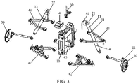
- the vehicle may further include two front wheels 30, a rear wheel (not shown), a steering arm 60, a front bogie 70 and a handlebar 80.
- the steering mechanism includes the upper suspension frame 41, the lower suspension frame 42, the damper 43 and the steering seat 44.
- the upper suspension frame 41 and the lower suspension frame 42 are oppositely disposed, the middle portion of the upper suspension frame 41 is fixed to the upper portion of the main frame 10 and the middle portion of the lower suspension frame 42 is fixed to the lower portion of the main frame 10.
- the two ends of the upper suspension frame 41 and the two ends of the lower suspension 42 are connected to the two front wheels through the upper end and the lower end of the steering seat 44 respectively.
- the damper 43 is horizontally disposed on the main frame 10 and the two ends of the damper 43 are hinged to the lower suspension frame 42.
- a lower end of the steering arm 60 is fixed to the main frame 10.
- An upper end of the steering arm 60 is fixed to a lower end of the front bogie 70.
- An upper end of the front bogie 70 is fixed to a middle portion of the handlebar 80.
- the tilting device for the vehicle when the tilting device for the vehicle includes the electronically controlled hydraulic rod disposed on each of both sides of the main frame 10 (including the first electronically controlled hydraulic rod and the second electronically controlled hydraulic rod, the first electronically controlled hydraulic rod includes the first hydraulic rod body 11 and the first micro motor 21, and the second electronically controlled hydraulic rod includes the second hydraulic rod body 12 and the second micro motor 22), the cylinder body 13 in the electronically controlled hydraulic rod is hinged to the upper portion of the main frame 10, and the piston rod 14 is hinged to the lower suspension frame 42.
- both the upper suspension frame 41 and the lower suspension frame 42 may be independent suspension frames, or may be non-independent suspension frames.
- the vehicle may be tiltable vehicles such as a tricycle, an inverted tricycle and a four-wheeler.
- the vehicle provided in the embodiment includes the tilting device for the vehicle provided in the embodiments of the present invention, and has the dame functions and beneficial effects.
- An embodiment of the present invention further provides a tilting method for a vehicle, which may be executed by the tilting device for the vehicle provided in the embodiments of the present invention. Specifically, as illustrated in FIG. 6 , the tilting method for the vehicle in the embodiment includes the steps described below.
- step 110 the control mechanism receives a trigger signal.
- the trigger signal when the tilt angle of the vehicle is manually controlled, the trigger signal is the lock signal or the unlock signal triggered by a user through the locking switch.
- the trigger signal is the state information of the vehicle.
- step 120 the control mechanism controls the tilt angle of the vehicle by controlling the detent mechanism.
- the tilt angle is the angle between the vehicle and the first plane.
- the first plane extends in the longitudinal direction of the vehicle and is perpendicular to the ground.
- the tilting method for the vehicle further includes the following step: the control mechanism detects the state of the vehicle through the detection mechanism.
- the state of the vehicle includes at least the tilt angle of the vehicle.
- the control mechanism controls the tilt angle of the vehicle by controlling the detent mechanism according to the state of the vehicle.
- the tilt angle may be detected by the gyroscope.
- the locking portion is controlled to lock the tiltable portion to fix the main frame of the vehicle.
- the tiltable portion is disposed on the main frame of the vehicle to enable the main frame to tilt left and right.
- the locking portion is disposed on the tiltable portion and configured to lock or unlock the tiltable portion.
- the locking portion and the tiltable portion may be the electronically controlled hydraulic rod in the embodiments described above.
- the tilting method for the vehicle in the embodiment and the tilting device for the vehicle provided in the embodiments of the present invention belong to a general inventive concept.
- the tilting method for the vehicle may be executed by the tilting device for the vehicle and has the same functions and beneficial effects. Details of the embodiment may refer to the embodiments described above of the tilting device for the vehicle.
- detecting the state of the vehicle includes detecting the tilt angle and the traveling speed of the vehicle.
- the tilting method for the vehicle further includes determining, according to the traveling speed of the vehicle, whether the traveling speed of the vehicle is less than the preset speed.
- the preset speed may be 2 km/h.
- the traveling speed of the vehicle is determined to be less than the preset speed, whether the tilt angle is less than the preset angle is determined according to the state of the vehicle. If the traveling speed of the vehicle is determined to be greater than or equal to the preset speed, the locking portion is controlled to unlock the tiltable portion.
- detecting the state of the vehicle further includes detecting whether the vehicle is in the traveling state before detecting the tilt angle and the traveling speed of the vehicle.
- the traveling speed of the vehicle is less than the preset speed is determined. If the vehicle is determined to be not in the traveling state, the locking portion is controlled to lock the tiltable portion.
- the method further includes the step described below.
- the tilting method for the vehicle may specifically include the steps described below.
- step 210 when the vehicle is started, whether each module of the vehicle fails is detected.
- step 270 is performed; if it is detected that each module of the vehicle is normal, step 220 is performed.
- step 220 whether the vehicle is in the traveling state is detected.
- step 230 is performed; if it is detected that the vehicle stops, step 250 is performed.
- step 230 whether the traveling speed of the vehicle is less than the preset speed is determined.
- step 240 If the traveling speed of the vehicle is determined to be less than the preset speed, step 240 is performed; if the traveling speed of the vehicle is determined to be greater than or equal to the preset speed, step 290 is performed.
- step 240 whether the tilt angle is less than the preset angle is determined.
- step 250 is performed; if the tilt angle is determined to be greater than or equal to the preset angle, step 280 is performed.
- step 250 whether the tiltable portion is locked is detected.
- step 260 the locking portion is controlled to lock the tiltable portion.
- step 270 the fault warning is issued.
- step 280 the imbalance warning is issued.
- step 290 whether the tiltable portion is locked is detected.
- step 300 the locking portion is controlled to unlock the tiltable portion.
Landscapes
- Engineering & Computer Science (AREA)
- Mechanical Engineering (AREA)
- Vehicle Body Suspensions (AREA)
- Automatic Cycles, And Cycles In General (AREA)
Applications Claiming Priority (1)
| Application Number | Priority Date | Filing Date | Title |
|---|---|---|---|
| CN201811647719.9A CN109693745B (zh) | 2018-12-29 | 2018-12-29 | 一种车辆的倾斜装置、方法及车辆 |
Publications (2)
| Publication Number | Publication Date |
|---|---|
| EP3674194A1 true EP3674194A1 (fr) | 2020-07-01 |
| EP3674194B1 EP3674194B1 (fr) | 2025-02-12 |
Family
ID=66232441
Family Applications (1)
| Application Number | Title | Priority Date | Filing Date |
|---|---|---|---|
| EP19170871.8A Active EP3674194B1 (fr) | 2018-12-29 | 2019-04-24 | Dispositif et procédé de basculement pour véhicule et véhicule |
Country Status (3)
| Country | Link |
|---|---|
| US (1) | US11001328B2 (fr) |
| EP (1) | EP3674194B1 (fr) |
| CN (1) | CN109693745B (fr) |
Families Citing this family (4)
| Publication number | Priority date | Publication date | Assignee | Title |
|---|---|---|---|---|
| JP7132102B2 (ja) * | 2018-11-22 | 2022-09-06 | カワサキモータース株式会社 | 走行車両 |
| CN210761116U (zh) * | 2019-06-25 | 2020-06-16 | 郑菊连 | 一种两轮式自动平衡复位机构及系统 |
| EP4005910A4 (fr) * | 2019-08-30 | 2022-09-28 | Yamaha Hatsudoki Kabushiki Kaisha | Véhicule inclinable |
| JP2024070309A (ja) * | 2022-11-11 | 2024-05-23 | ロベルト・ボッシュ・ゲゼルシャフト・ミト・ベシュレンクテル・ハフツング | ロール制御システム及び車両 |
Citations (6)
| Publication number | Priority date | Publication date | Assignee | Title |
|---|---|---|---|---|
| US20080012262A1 (en) * | 2006-06-23 | 2008-01-17 | Stefano Carabelli | Suspension tilting module for a wheeled vehicle and a wheeled vehicle equipped with said suspension tilting module |
| EP2154050B1 (fr) * | 2008-07-31 | 2011-06-08 | Yamaha Hatsudoki Kabushiki Kaisha | Système de contrôle d'inclinaison de corps, et véhicule de type à monture doté de celui-ci |
| EP2019772B1 (fr) * | 2006-04-26 | 2013-08-28 | Vectrix International Limited | Véhicule avec système d'inclinaison verrouillable |
| EP3103713A1 (fr) * | 2015-06-04 | 2016-12-14 | Shengzhou Zhonggong Electrical, Ltd. | Tricycle inversé |
| EP3124366A1 (fr) * | 2014-03-24 | 2017-02-01 | Yamaha Hatsudoki Kabushiki Kaisha | Véhicule à selle |
| EP3366558A1 (fr) * | 2015-11-20 | 2018-08-29 | Yamaha Hatsudoki Kabushiki Kaisha | Véhicule à inclinaison |
Family Cites Families (16)
| Publication number | Priority date | Publication date | Assignee | Title |
|---|---|---|---|---|
| JP2002337779A (ja) * | 2001-05-21 | 2002-11-27 | Abanteku:Kk | 三輪車 |
| US8123240B2 (en) * | 2009-07-10 | 2012-02-28 | Bombardier Recreational Products Inc. | Control system for leaning vehicle |
| CN102092435B (zh) * | 2009-12-10 | 2014-11-05 | 光阳工业股份有限公司 | 具有两前轮车辆的防止倾倒装置 |
| FR2993207B1 (fr) * | 2012-07-11 | 2014-08-15 | Peugeot Motocycles Sa | Train roulant pour vehicule a deux roues avant inclinables lateralement |
| US9238482B2 (en) * | 2012-08-14 | 2016-01-19 | Aeon Motor Co., Ltd. | Road holding ability mechanism for the two front wheels of a motorcycle |
| US9061564B1 (en) * | 2013-12-18 | 2015-06-23 | Automotive Research & Testing Center | Active vehicle with a variable inclination apparatus and method of using the same |
| WO2015115110A1 (fr) * | 2014-01-31 | 2015-08-06 | ヤマハ発動機株式会社 | Véhicule |
| JPWO2015146679A1 (ja) * | 2014-03-24 | 2017-04-13 | ヤマハ発動機株式会社 | 鞍乗型車両 |
| ES2914152T3 (es) * | 2014-03-24 | 2022-06-07 | Yamaha Motor Co Ltd | Vehículo de tipo sillín |
| IT201600097100A1 (it) * | 2016-09-28 | 2018-03-28 | Piaggio & C Spa | Assieme di sospensione per un veicolo basculante, avantreno e veicolo basculante |
| CN206501962U (zh) * | 2016-11-28 | 2017-09-19 | 重庆力之星机车制造有限责任公司 | 一种倒三轮车的前悬架偏摆机构 |
| CN206407056U (zh) * | 2016-12-13 | 2017-08-15 | 重庆宗申技术开发研究有限公司 | 一种倒三轮车用前悬架偏摆结构 |
| CN107364298A (zh) * | 2017-07-19 | 2017-11-21 | 重庆宗申技术开发研究有限公司 | 倒三轮偏摆锁止结构 |
| DE112018005593T5 (de) * | 2017-11-15 | 2020-07-30 | Sway Motorsports Llc | Steuersystem für neigbares Fahrzeug |
| ES2934082T3 (es) * | 2019-02-19 | 2023-02-16 | Garcia Atance Fatjo Gonzalo | Triciclo con suspensión de ruedas basculantes en altura relacionada con el manillar de conducción |
| US11338877B2 (en) * | 2019-06-25 | 2022-05-24 | Julian Zheng | Two-wheel automatic balance reset mechanism and system |
-
2018
- 2018-12-29 CN CN201811647719.9A patent/CN109693745B/zh not_active Expired - Fee Related
-
2019
- 2019-04-24 EP EP19170871.8A patent/EP3674194B1/fr active Active
- 2019-05-09 US US16/408,015 patent/US11001328B2/en active Active - Reinstated
Patent Citations (6)
| Publication number | Priority date | Publication date | Assignee | Title |
|---|---|---|---|---|
| EP2019772B1 (fr) * | 2006-04-26 | 2013-08-28 | Vectrix International Limited | Véhicule avec système d'inclinaison verrouillable |
| US20080012262A1 (en) * | 2006-06-23 | 2008-01-17 | Stefano Carabelli | Suspension tilting module for a wheeled vehicle and a wheeled vehicle equipped with said suspension tilting module |
| EP2154050B1 (fr) * | 2008-07-31 | 2011-06-08 | Yamaha Hatsudoki Kabushiki Kaisha | Système de contrôle d'inclinaison de corps, et véhicule de type à monture doté de celui-ci |
| EP3124366A1 (fr) * | 2014-03-24 | 2017-02-01 | Yamaha Hatsudoki Kabushiki Kaisha | Véhicule à selle |
| EP3103713A1 (fr) * | 2015-06-04 | 2016-12-14 | Shengzhou Zhonggong Electrical, Ltd. | Tricycle inversé |
| EP3366558A1 (fr) * | 2015-11-20 | 2018-08-29 | Yamaha Hatsudoki Kabushiki Kaisha | Véhicule à inclinaison |
Also Published As
| Publication number | Publication date |
|---|---|
| US20200207436A1 (en) | 2020-07-02 |
| CN109693745A (zh) | 2019-04-30 |
| US11001328B2 (en) | 2021-05-11 |
| CN109693745B (zh) | 2021-04-02 |
| EP3674194B1 (fr) | 2025-02-12 |
Similar Documents
| Publication | Publication Date | Title |
|---|---|---|
| US11001328B2 (en) | Tilting device and method for vehicle and vehicle | |
| US7743871B2 (en) | Anti-tilt apparatus and frame structure of tilting vehicle using the same | |
| US6047229A (en) | Tilt control apparatus for industrial vehicles | |
| EP3192730B1 (fr) | Commande d'inclinaison pour véhicules basculeurs | |
| US6250649B1 (en) | Multi-track curve tilting vehicle | |
| CN110901816B (zh) | 一种悬架总成、控制方法及车辆 | |
| US20100324808A1 (en) | Motorised vehicle with controlled inclination | |
| JP4482442B2 (ja) | 車両 | |
| CN1980804A (zh) | 具有有限倾角的机动车 | |
| US20250128781A1 (en) | Straddled vehicle | |
| CN110843984B (zh) | 一种人机联合平衡车 | |
| CN110901815B (zh) | 一种悬架总成、控制方法及车辆 | |
| US12304581B2 (en) | Saddle-riding vehicle | |
| JPS5851609Y2 (ja) | 車輌における車体傾斜装置 | |
| EP3333121B1 (fr) | Véhicule industriel | |
| TWI862797B (zh) | 具有至少三個輪子之可側傾車輛,安全裝置及側傾方法 | |
| JPS60191812A (ja) | 車両用サスペンシヨン制御装置 | |
| US12194801B2 (en) | Roll control system and vehicle | |
| KR0137236B1 (ko) | 동력 조향 장치의 토션바의 비틀림 응력 조절장치 | |
| KR101919446B1 (ko) | 이륜 현가 장치 | |
| CN113500885A (zh) | 一种车辆悬挂装置及车辆控制方法 | |
| JPS6359899B2 (fr) | ||
| KR100203835B1 (ko) | 자동차 수평 조절장치 | |
| CN119953483A (zh) | 三轮机车的倾斜控制装置 | |
| KR200336116Y1 (ko) | 자동차의 코너링 제어 시스템 |
Legal Events
| Date | Code | Title | Description |
|---|---|---|---|
| PUAI | Public reference made under article 153(3) epc to a published international application that has entered the european phase |
Free format text: ORIGINAL CODE: 0009012 |
|
| STAA | Information on the status of an ep patent application or granted ep patent |
Free format text: STATUS: REQUEST FOR EXAMINATION WAS MADE |
|
| 17P | Request for examination filed |
Effective date: 20190424 |
|
| AK | Designated contracting states |
Kind code of ref document: A1 Designated state(s): AL AT BE BG CH CY CZ DE DK EE ES FI FR GB GR HR HU IE IS IT LI LT LU LV MC MK MT NL NO PL PT RO RS SE SI SK SM TR |
|
| AX | Request for extension of the european patent |
Extension state: BA ME |
|
| STAA | Information on the status of an ep patent application or granted ep patent |
Free format text: STATUS: EXAMINATION IS IN PROGRESS |
|
| 17Q | First examination report despatched |
Effective date: 20220425 |
|
| GRAP | Despatch of communication of intention to grant a patent |
Free format text: ORIGINAL CODE: EPIDOSNIGR1 |
|
| STAA | Information on the status of an ep patent application or granted ep patent |
Free format text: STATUS: GRANT OF PATENT IS INTENDED |
|
| INTG | Intention to grant announced |
Effective date: 20240918 |
|
| GRAS | Grant fee paid |
Free format text: ORIGINAL CODE: EPIDOSNIGR3 |
|
| GRAA | (expected) grant |
Free format text: ORIGINAL CODE: 0009210 |
|
| STAA | Information on the status of an ep patent application or granted ep patent |
Free format text: STATUS: THE PATENT HAS BEEN GRANTED |
|
| AK | Designated contracting states |
Kind code of ref document: B1 Designated state(s): AL AT BE BG CH CY CZ DE DK EE ES FI FR GB GR HR HU IE IS IT LI LT LU LV MC MK MT NL NO PL PT RO RS SE SI SK SM TR |
|
| REG | Reference to a national code |
Ref country code: GB Ref legal event code: FG4D |
|
| REG | Reference to a national code |
Ref country code: CH Ref legal event code: EP |
|
| REG | Reference to a national code |
Ref country code: DE Ref legal event code: R096 Ref document number: 602019065683 Country of ref document: DE |
|
| REG | Reference to a national code |
Ref country code: IE Ref legal event code: FG4D |
|
| REG | Reference to a national code |
Ref country code: NL Ref legal event code: MP Effective date: 20250212 |
|
| PG25 | Lapsed in a contracting state [announced via postgrant information from national office to epo] |
Ref country code: RS Free format text: LAPSE BECAUSE OF FAILURE TO SUBMIT A TRANSLATION OF THE DESCRIPTION OR TO PAY THE FEE WITHIN THE PRESCRIBED TIME-LIMIT Effective date: 20250512 |
|
| PG25 | Lapsed in a contracting state [announced via postgrant information from national office to epo] |
Ref country code: FI Free format text: LAPSE BECAUSE OF FAILURE TO SUBMIT A TRANSLATION OF THE DESCRIPTION OR TO PAY THE FEE WITHIN THE PRESCRIBED TIME-LIMIT Effective date: 20250212 |
|
| PG25 | Lapsed in a contracting state [announced via postgrant information from national office to epo] |
Ref country code: PL Free format text: LAPSE BECAUSE OF FAILURE TO SUBMIT A TRANSLATION OF THE DESCRIPTION OR TO PAY THE FEE WITHIN THE PRESCRIBED TIME-LIMIT Effective date: 20250212 |
|
| PG25 | Lapsed in a contracting state [announced via postgrant information from national office to epo] |
Ref country code: ES Free format text: LAPSE BECAUSE OF FAILURE TO SUBMIT A TRANSLATION OF THE DESCRIPTION OR TO PAY THE FEE WITHIN THE PRESCRIBED TIME-LIMIT Effective date: 20250212 |
|
| REG | Reference to a national code |
Ref country code: LT Ref legal event code: MG9D |
|
| PG25 | Lapsed in a contracting state [announced via postgrant information from national office to epo] |
Ref country code: NO Free format text: LAPSE BECAUSE OF FAILURE TO SUBMIT A TRANSLATION OF THE DESCRIPTION OR TO PAY THE FEE WITHIN THE PRESCRIBED TIME-LIMIT Effective date: 20250512 Ref country code: IS Free format text: LAPSE BECAUSE OF FAILURE TO SUBMIT A TRANSLATION OF THE DESCRIPTION OR TO PAY THE FEE WITHIN THE PRESCRIBED TIME-LIMIT Effective date: 20250612 |
|
| PG25 | Lapsed in a contracting state [announced via postgrant information from national office to epo] |
Ref country code: NL Free format text: LAPSE BECAUSE OF FAILURE TO SUBMIT A TRANSLATION OF THE DESCRIPTION OR TO PAY THE FEE WITHIN THE PRESCRIBED TIME-LIMIT Effective date: 20250212 |
|
| PG25 | Lapsed in a contracting state [announced via postgrant information from national office to epo] |
Ref country code: HR Free format text: LAPSE BECAUSE OF FAILURE TO SUBMIT A TRANSLATION OF THE DESCRIPTION OR TO PAY THE FEE WITHIN THE PRESCRIBED TIME-LIMIT Effective date: 20250212 |
|
| PG25 | Lapsed in a contracting state [announced via postgrant information from national office to epo] |
Ref country code: LV Free format text: LAPSE BECAUSE OF FAILURE TO SUBMIT A TRANSLATION OF THE DESCRIPTION OR TO PAY THE FEE WITHIN THE PRESCRIBED TIME-LIMIT Effective date: 20250212 Ref country code: PT Free format text: LAPSE BECAUSE OF FAILURE TO SUBMIT A TRANSLATION OF THE DESCRIPTION OR TO PAY THE FEE WITHIN THE PRESCRIBED TIME-LIMIT Effective date: 20250612 |
|
| PG25 | Lapsed in a contracting state [announced via postgrant information from national office to epo] |
Ref country code: GR Free format text: LAPSE BECAUSE OF FAILURE TO SUBMIT A TRANSLATION OF THE DESCRIPTION OR TO PAY THE FEE WITHIN THE PRESCRIBED TIME-LIMIT Effective date: 20250513 Ref country code: BG Free format text: LAPSE BECAUSE OF FAILURE TO SUBMIT A TRANSLATION OF THE DESCRIPTION OR TO PAY THE FEE WITHIN THE PRESCRIBED TIME-LIMIT Effective date: 20250212 |
|
| REG | Reference to a national code |
Ref country code: AT Ref legal event code: MK05 Ref document number: 1765836 Country of ref document: AT Kind code of ref document: T Effective date: 20250212 |
|
| PG25 | Lapsed in a contracting state [announced via postgrant information from national office to epo] |
Ref country code: SE Free format text: LAPSE BECAUSE OF FAILURE TO SUBMIT A TRANSLATION OF THE DESCRIPTION OR TO PAY THE FEE WITHIN THE PRESCRIBED TIME-LIMIT Effective date: 20250212 |
|
| PG25 | Lapsed in a contracting state [announced via postgrant information from national office to epo] |
Ref country code: SM Free format text: LAPSE BECAUSE OF FAILURE TO SUBMIT A TRANSLATION OF THE DESCRIPTION OR TO PAY THE FEE WITHIN THE PRESCRIBED TIME-LIMIT Effective date: 20250212 |
|
| PG25 | Lapsed in a contracting state [announced via postgrant information from national office to epo] |
Ref country code: DK Free format text: LAPSE BECAUSE OF FAILURE TO SUBMIT A TRANSLATION OF THE DESCRIPTION OR TO PAY THE FEE WITHIN THE PRESCRIBED TIME-LIMIT Effective date: 20250212 |
|
| PG25 | Lapsed in a contracting state [announced via postgrant information from national office to epo] |
Ref country code: IT Free format text: LAPSE BECAUSE OF FAILURE TO SUBMIT A TRANSLATION OF THE DESCRIPTION OR TO PAY THE FEE WITHIN THE PRESCRIBED TIME-LIMIT Effective date: 20250212 |
|
| PG25 | Lapsed in a contracting state [announced via postgrant information from national office to epo] |
Ref country code: AT Free format text: LAPSE BECAUSE OF FAILURE TO SUBMIT A TRANSLATION OF THE DESCRIPTION OR TO PAY THE FEE WITHIN THE PRESCRIBED TIME-LIMIT Effective date: 20250212 |
|
| PG25 | Lapsed in a contracting state [announced via postgrant information from national office to epo] |
Ref country code: CZ Free format text: LAPSE BECAUSE OF FAILURE TO SUBMIT A TRANSLATION OF THE DESCRIPTION OR TO PAY THE FEE WITHIN THE PRESCRIBED TIME-LIMIT Effective date: 20250212 Ref country code: EE Free format text: LAPSE BECAUSE OF FAILURE TO SUBMIT A TRANSLATION OF THE DESCRIPTION OR TO PAY THE FEE WITHIN THE PRESCRIBED TIME-LIMIT Effective date: 20250212 |
|
| PG25 | Lapsed in a contracting state [announced via postgrant information from national office to epo] |
Ref country code: RO Free format text: LAPSE BECAUSE OF FAILURE TO SUBMIT A TRANSLATION OF THE DESCRIPTION OR TO PAY THE FEE WITHIN THE PRESCRIBED TIME-LIMIT Effective date: 20250212 |
|
| PG25 | Lapsed in a contracting state [announced via postgrant information from national office to epo] |
Ref country code: SK Free format text: LAPSE BECAUSE OF FAILURE TO SUBMIT A TRANSLATION OF THE DESCRIPTION OR TO PAY THE FEE WITHIN THE PRESCRIBED TIME-LIMIT Effective date: 20250212 |
|
| REG | Reference to a national code |
Ref country code: DE Ref legal event code: R097 Ref document number: 602019065683 Country of ref document: DE |
|
| REG | Reference to a national code |
Ref country code: CH Ref legal event code: H13 Free format text: ST27 STATUS EVENT CODE: U-0-0-H10-H13 (AS PROVIDED BY THE NATIONAL OFFICE) Effective date: 20251125 |
|
| PG25 | Lapsed in a contracting state [announced via postgrant information from national office to epo] |
Ref country code: LU Free format text: LAPSE BECAUSE OF NON-PAYMENT OF DUE FEES Effective date: 20250424 |
|
| PLBE | No opposition filed within time limit |
Free format text: ORIGINAL CODE: 0009261 |
|
| STAA | Information on the status of an ep patent application or granted ep patent |
Free format text: STATUS: NO OPPOSITION FILED WITHIN TIME LIMIT |
|
| PG25 | Lapsed in a contracting state [announced via postgrant information from national office to epo] |
Ref country code: MC Free format text: LAPSE BECAUSE OF FAILURE TO SUBMIT A TRANSLATION OF THE DESCRIPTION OR TO PAY THE FEE WITHIN THE PRESCRIBED TIME-LIMIT Effective date: 20250212 |
|
| REG | Reference to a national code |
Ref country code: BE Ref legal event code: MM Effective date: 20250430 |
|
| PGFP | Annual fee paid to national office [announced via postgrant information from national office to epo] |
Ref country code: DE Payment date: 20251017 Year of fee payment: 7 |
|
| PG25 | Lapsed in a contracting state [announced via postgrant information from national office to epo] |
Ref country code: FR Free format text: LAPSE BECAUSE OF NON-PAYMENT OF DUE FEES Effective date: 20250430 |
|
| PG25 | Lapsed in a contracting state [announced via postgrant information from national office to epo] |
Ref country code: BE Free format text: LAPSE BECAUSE OF NON-PAYMENT OF DUE FEES Effective date: 20250430 |
|
| PG25 | Lapsed in a contracting state [announced via postgrant information from national office to epo] |
Ref country code: CH Free format text: LAPSE BECAUSE OF NON-PAYMENT OF DUE FEES Effective date: 20250430 |
|
| 26N | No opposition filed |
Effective date: 20251113 |
|
| GBPC | Gb: european patent ceased through non-payment of renewal fee |
Effective date: 20250512 |
|
| PG25 | Lapsed in a contracting state [announced via postgrant information from national office to epo] |
Ref country code: GB Free format text: LAPSE BECAUSE OF NON-PAYMENT OF DUE FEES Effective date: 20250512 |
|
| PG25 | Lapsed in a contracting state [announced via postgrant information from national office to epo] |
Ref country code: IE Free format text: LAPSE BECAUSE OF NON-PAYMENT OF DUE FEES Effective date: 20250424 |