EP3674482A1 - Befestigungsvorrichtung einer schiene - Google Patents
Befestigungsvorrichtung einer schiene Download PDFInfo
- Publication number
- EP3674482A1 EP3674482A1 EP19219643.4A EP19219643A EP3674482A1 EP 3674482 A1 EP3674482 A1 EP 3674482A1 EP 19219643 A EP19219643 A EP 19219643A EP 3674482 A1 EP3674482 A1 EP 3674482A1
- Authority
- EP
- European Patent Office
- Prior art keywords
- cam
- rail
- passage
- fixing
- face
- Prior art date
- Legal status (The legal status is an assumption and is not a legal conclusion. Google has not performed a legal analysis and makes no representation as to the accuracy of the status listed.)
- Granted
Links
Images



Classifications
-
- E—FIXED CONSTRUCTIONS
- E01—CONSTRUCTION OF ROADS, RAILWAYS, OR BRIDGES
- E01B—PERMANENT WAY; PERMANENT-WAY TOOLS; MACHINES FOR MAKING RAILWAYS OF ALL KINDS
- E01B9/00—Fastening rails on sleepers, or the like
- E01B9/66—Rail fastenings allowing the adjustment of the position of the rails, so far as not included in the preceding groups
-
- B—PERFORMING OPERATIONS; TRANSPORTING
- B66—HOISTING; LIFTING; HAULING
- B66C—CRANES; LOAD-ENGAGING ELEMENTS OR DEVICES FOR CRANES, CAPSTANS, WINCHES, OR TACKLES
- B66C7/00—Runways, tracks or trackways for trolleys or cranes
- B66C7/08—Constructional features of runway rails or rail mountings
-
- E—FIXED CONSTRUCTIONS
- E01—CONSTRUCTION OF ROADS, RAILWAYS, OR BRIDGES
- E01B—PERMANENT WAY; PERMANENT-WAY TOOLS; MACHINES FOR MAKING RAILWAYS OF ALL KINDS
- E01B9/00—Fastening rails on sleepers, or the like
- E01B9/02—Fastening rails, tie-plates, or chairs directly on sleepers or foundations; Means therefor
- E01B9/32—Fastening on steel sleepers with clamp members
Definitions
- the present invention relates to a device for fixing running rails on a support structure.
- the rail support may include a support plate or a support cross member on which the fasteners, also called clips, flanges, or even toads are arranged so as to hold the rail in position.
- the rail is commonly composed of a lower part or shoe which rests on the rail support, a central part or core, vertical which links the lower part to an upper part.
- the upper part has a rolling or circulation head for a vehicle.
- the fastener generally comes to press on the top of the shoe by means of a tab projecting towards the rail.
- the attachment may alternatively, or in addition, bear against the outer edge of the pad to form a lateral stop for positioning the rail.
- the fasteners are bolted and / or welded to the rail support.
- the commonly used fasteners include a base welded to the support and an upper part forming a rail retaining flange, removably attached to the base.
- the fasteners are anchored to the mounting bracket by means of bolts. Bolted fasteners are easier to dismantle but are not suitable for supporting loads as high as welded fasteners.
- the clip comprises a body from which extends a retaining tab provided with an elastic pad (also called nose) coming into contact with the upper face of a pad of a rail.
- the body includes an oblong opening which allows the passage of a fixing bolt, while allowing an adjustment of the body in translation relative to the lateral face of the rail, in order to limit the lateral displacement of the rail.
- the bolt is first put in place and then the body is engaged on the bolt.
- a washer is placed between the tightening nut and the body.
- the washer has a lower face with a profile which cooperates with the upper surface of the body around the oblong hole, so as to achieve self-locking.
- the elastic pad is generally an elastomer which can be either vulcanized or bonded to the face of the retaining tab facing the pad. Its installation typically requires passage through an oven at a temperature of 200 ° C for 15 to 20 min.
- Gantrail or Gantrex clips are very widely used, there are some problems. During installation, the position of the clip is adjusted along the rail after partial clamping of the clip by hammer blows. This implementation is imprecise. In addition, the washer being a separate part, there is a risk of losing it during transport. Finally, the elastic pad (or nose) remains a fragile piece, sensitive to operating conditions: rain, salt, UV, temperature. The clips are therefore often replaced during track maintenance campaigns because the elastic pad (or nose) is worn.
- the object of the present invention is to provide an improved fixing device for fixing a rail to a support structure which does not have the drawbacks of known fasteners.
- the device according to the invention also comprises positioning means making it possible to adjust the position of the body relative to the rail when the fixing member is engaged through the body, in particular in the through passage.
- the compression nose is fixed to the retaining lug by removable fixing means.
- the fixing member which generally has the shape of a stud or of a cylindrical rod with a threaded end, is therefore engaged from bottom to top through the body.
- the threaded end protrudes from the top of the body, and a nut is screwed onto this end, thus pressing on the upper part of the body to tighten it against the support structure.
- the compression nose is one of the elements of the device whose wear is the earliest. This is due to the fact that it is often made of a polymer material, in particular an elastomer.
- the removable fixing means at the compression nose allow replacement of the nose, in the event of wear thereof, independently of the other elements of the device and therefore save a complete manufacturing process of the device each once a repair is required.
- the nose can be fixed to the holding tab by elastic deformation and / or complementary shapes.
- the nose in the form of a bar, in particular with a substantially rectangular or trapezoidal section, said bar having a fixing face in contact with the holding face of the fixing lug, and an opposite bearing face, intended to come in contact with the upper face of the rail pad.
- At least two studs protrude from the fixing face of the nose are engaged by force in holes, preferably through, in the tab.
- the nose is made of polymer material. It is typically made by injection molding. Any suitable polymer may be used, in particular elastomers such as, for example, SIPLOPRENE or MEGOL.
- the nose can be made of metal, in particular steel.
- the body comprises a through passage in the form of an oblong hole and the fixing member is anchored in a fixed base supporting the body, welded to the support structure of the rail, and is engaged in the through passage of the body.
- the base preferably comprises guide faces in translation of the body.
- the positioning means comprise a cam housed in the body and comprising a through passage for the fixing member.
- the cam is movable in the body so as to allow the modification of the relative position of the fixing member relative to the body.
- the cam is housed in a cylindrical through passage, and is movable in rotation in this passage around a pivot axis passing through its center.
- the through passage for the fixing member is offset from the pivot axis.
- the cam comprises a lateral surface with an annular portion of tapered shape, in particular conical, which rests on a corresponding surface of the internal wall of the cylindrical passage.
- the fixing member comprises a screw whose head is housed under the body (blocked in the base or in the support structure) and a nut screwed onto the end of the screw protruding from the through passage and loaded against the body, respectively the cam.
- the through passage advantageously comprises a thread
- the cam comprises a thread corresponding to the thread of the passage.
- the cam thread is loaded against the thread of the passage by tightening a nut screwed onto the end of the screw fixing member and protruding from the cam.
- the thread / tapping ensures good circumferential contact between the two parts.
- the thread and tapping are preferably configured so that in the fully screwed position of the cam, called the starting or low position, the through passage for the fixing member is in a distal position of the tab, and after a rotation of approximately half a turn, the cam is in the high position, raised relative to the starting position, and the through passage for the fixing member is in a position proximal to the tab. Thanks to this constructive measure, if the cam is urged to move from the starting position towards the high position, the cam undergoes an ascent which is braked by the nut.
- a locking stop is preferably provided in the passage to limit the rotation of the cam.
- the upper part of the cam is shaped to cooperate with said cam so as to limit rotation to less than one turn, in particular about 1 half-turn.
- a flange protrudes from the upper face of the cam and surrounds the through passage of the fixing member, the flange having an external contour adapted to be engaged with a tool making it possible to apply a rotational movement to the cam, the outer contour preferably being hexagonal.
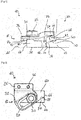
- the device 10 comprises a body 12 with a retaining tab 26, integral with the latter, which extends laterally beyond the body 12 so as to come above a lateral shoe 14 of a rail 15 of bearing (shown abstractly).
- the body 12 cooperates with a base 16 fixed on a support structure 17 of the rail 15, as typically a spar or a support plate. Once assembled, the body 12 is typically fixed in contact with the pad 14.
- the reference sign 24 designates a lateral contact face of the body, under the tab 26, oriented towards the pad.
- the body 12 rests, by its lower portion called the sole 18 on the base 16, which is fixed to the support structure by welding.
- This type of device 10 is thus commonly called a welding clip.
- the body 12 has a through passage 20, here constituted by an oblong hole, intended to accommodate a screw fixing member 22.
- the fixing member 22 is generally a bolt, and in particular a stud 28 and a nut 30.
- the stud 28 is engaged in the through passage 20 of the body 12, from the bottom up and protrudes from the upper surface of the body 32 to level of which the nut 30 is disposed.
- the stud 28 is typically anchored in the welded base 16.
- the base 16 is provided with a housing formed by a notch 34 allowing the insertion of the stud 28 in the base 16.
- a head 36 of the stud comprises a rotation blocking element maintained by complementarity shaped in the notch 34.
- the head 36 of the stud is rectangular, just like the notch 34.
- the contact face 24 is turned towards the rail, and comes into contact with an outer edge 38 of the shoe 14 of the rail to limit the lateral movement of the rail.
- the retaining tab 26 extends above the shoe, from the body 12, in a substantially horizontal plane.
- the purpose of tab 26 is to limit the vertical movement of the rail. It bears on an upper face 40 of the pad via a compression nose 42.
- the nose 42 is fixed in a lower face called the holding face 44 of the tab 26, facing the upper face 40 of the shoe 14.
- the compression nose 42 is fixed to the retaining tab 26 by removable fixing means 46.
- the nose 42 can thus be fixed to the body 12 of the device 10, then removed from the body 12 without impacting the quality and functionality of other clip elements 10.
- the compression nose 42 also called compression pad, is in the form of a bar with a substantially rectangular or trapezoidal section, which has a fixing face 48 in contact with the holding face 44 of the tab 26, and an opposite bearing face 50 in contact with the upper face 40 of the shoe 14 of the rail.
- the height of the nose 42 between the fixing face 48 and the bearing face 50 is chosen as a function of the height of the shoe of the rail on which the device 10 is to be mounted.
- the device 10 is therefore adaptable to different types of rails by modifying the profile of the nose 42 which is attached to the tab 26.
- the bearing face 50 of the nose 42 can be flat or, as shown in the figures, concave.
- the concavity of the lower face allows the nose 42 to deform against the pad and to conform to the shape of the pad to increase its contact surface.
- the fixing face 48 comprises a flat part 52 corresponding with the holding face of the tab 26 of the body 12, and comprises two studs 46. These studs can for example be cylindrical and / or conical.
- the pins 46 are housed in holes 54 passing through the retaining tab 26; the holes 54 having a profile which can be cylindrical and / or conical, compatible with the pins 46.
- the assembly of the nose is done in this case by pressing the pins 46 into the holes 54 of the retaining tab, in particular by pressing. The assembly process is thus very fast, and does not involve an expensive or complex machine.
- the stud / hole assembly thus forms a removable means of fixing the nose.
- the posts are dimensioned to allow their introduction into force into the holes 54 and a fixing by tight fit. Note that the holding force of the pins 46 is not critical, because in use the nose 42 is compressed against the tab is not likely to come off. The nose can be easily detached from the retaining tab by releasing the studs from the holes.
- any suitable fixing means can be used to make a removable connection between the compression nose 42 and the retaining tab 26 of the body of the device.
- the fixing means can comprise a fixing system by elastic deformation, a fixing system by complementary shape such as for example a dovetail connection, or even a fixing system by screwing, riveting or tightening nose against the underside of the retaining tab.
- the compression nose 42 is preferably made of an elastomeric material.
- the elastomeric material is advantageously adapted to the environment in which the rail will be placed.
- a method of manufacturing the nose by injection molding is preferred, but it is understood that any suitable manufacturing method can be used.
- the compression nose can also be made of metallic material, for example of steel of type S355 or the like.
- the retaining face 44 preferably comprises a slight recess (about 1 mm deep) in which the base of the nose 42 is housed. When the device is mounted against the rail pad, the nose is thus held at its base against forces transverse and longitudinal, which avoids shearing problems.
- the device 10 is further designed to allow the position of the body 12 to be adjusted relative to the rail, when the fixing member 22 is engaged in the through passage 20 (and therefore fixed).
- the oblong shape of the through passage 20 forms a positioning means which will make it possible to move the body 12 on the base 16 (fixed) in horizontal translation towards the shoe 14 of the rail.
- the base 16 is a substantially flat part which rests by its lower face 58 on the support structure 17 of the rail and which has an opposite upper face 60 supporting the body 12 of the device 10.
- the base 16 has vertical faces joining the lower face 58 to upper face 60.
- the vertical faces include a front face 62 facing the shoe 14 of the rail, a rear face 64 opposite the front face and two lateral faces 66. The welding is generally carried out all around the base 16.
- the body 12 has a lower face 75 which rests on the upper face 60 of the base.
- the device 10 is designed so that the movement of the body 12 on the base is guided.
- a first oblique vertical guide face 68 joining the front face 62 and a side face 66 is arranged to allow the body 12 to be guided on the base 16.
- the base 16 has a protruding element 70 above its upper face 60, and the projecting element 70 comprises a second guide face 72 parallel to the first guide face 68.
- the sole 18 of the body 12 which rests on the base 16 comprises two translation faces 74, parallel, vertical, arranged opposite the guide faces 68, 72 of the base 16.
- the two guide faces 68, 72 do so office of guide stops for the translation faces 74 of the body 12.
- the oblong hole 20 is oriented in its length in a direction parallel to the translation faces 74.
- the body can slide against the guide faces 68, 72 of the base 16, between two positions: an extreme distal position shown in the Figure 3 , wherein the body 12 is spaced from the shoe 14; and an extreme proximal position, shown in Figure 4 , in which the body 12 is in contact with the shoe 14.
- the upper face 60 of the base 16 has an inclination, not visible, relative to the lower face 58, which is oriented in the sliding direction of the body.
- This tilt creates an increase of thickness of the base 16 from the proximal edge of the rail to the distal edge of the rail.
- the lower face 75 of the body 12 then comprises an inclination similar to the inclination of the base 16, with a smaller thickness on the proximal side of the rail.
- These complementary inclinations imply an increase in the total thickness of the clip when the body 12 moves away from the rail on the base 16 (from the configuration Fig. 4 towards that of Fig. 3 ), which increases the clamping force applied by the nut and allows a self-tightening or self-locking effect.
- the nut After installation and positioning of the body, the nut is screwed so as to lock the device in position.
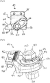
- a second embodiment of the rail fixing device 110 will now be described with reference to Figures 5 to 10 .
- This embodiment is described in comparison with the first embodiment, identical or similar elements are designated by the same reference signs, increased by 100.
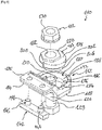
- the device 110 comprises a body 112 able to be disposed directly against a support structure of the rail 117 by means of a fixing member 122 passing through the body 112.
- the fixing member 122 is here a bolt comprising a screw 129 and a nut 130. It will be understood that the screw can be inserted into an orifice of the support structure or attached to it by any suitable means, in order to ensure anchoring the screw 129 in the track support.
- the fixing device 110 of the second embodiment is commonly called a bolt-on clip.
- the body 112 rests on the support structure 117 of the rail by its lower part called the sole 118, and has a contact face 124 oriented towards the shoe.
- the reference sign 126 designates a retaining tab integral with the body 112 and projecting beyond the contact face 124, therefore beyond the body 112.
- the contact face 124 and the retaining tab 126 are arranged similar to the first embodiment.
- the retaining tab 126 has a retaining face 144 facing an upper face 140 of the shoe 114, and a compression nose 142, in the form of bar, is fixed to the holding face 144 by removable fixing means 146, constituted here by studs projecting from the rear face of the nose.
- the device 110 also includes positioning means making it possible to adjust the position of the body 112 relative to the rail, when the fixing member is engaged in a through passage 120.
- the positioning means differ from those of the first embodiment. These comprise an eccentric cam 178 mounted on the screw 129 and housed in a passage formed by the through passage 120, generally circular.
- Cam 178 is a generally cylindrical part of revolution with a lateral surface in stages. On the side of the upper face 132 of the body 112, it is surmounted by a head constituted by an external flange 180 of hexagonal outline.
- the cam 178 is pivotable in the opening 120 around an axis R 1 passing substantially through the center of the passage 120 (cf. Fig. 9 ).
- the reference sign 182 designates a through hole, eccentric with respect to the axis of rotation R 1 of the cam, which allows the passage of the screw 129 through the cam 178, and therefore through the body 112.
- the axis R 2 is also at the center of the collar 180.
- the external collar 180 can be engaged by an appropriate key so as to rotate the cam 178 around the axis R 2 of the screw 129.
- the nut 130 is screwed onto the part of the screw 129 protruding from the head.
- the two extreme positions of the cam 178 are delimited by a finger 184 formed in an internal wall 176 of the through passage 120, and comprising two abutment faces 190 limiting the rotation of the cam 178.
- the cam carries at its upper section a projecting annular segment 185 extending over approximately 180 °.
- the internal wall 176 defines a generally conical passage: there is an inlet section 188, an intermediate section 187 conical (frustoconical) and a lower circular section 186 straight.
- the passage section is reduced in the direction of the lower section.
- the cam 178 has a generally conical body and comprises a side wall 200 having an upper section 202, a conical intermediate section 204 and a circular lower section 206 of reduced diameter.
- Threads 208 and 210 are provided respectively on the wall 200 of the cam 178 and the wall 176, over approximately one revolution, at the level of the conical parts. In the position of Figures 7 and 8 the cam 178 is screwed into the opening, abutting on the finger 184. It is observed that the shapes of the cam 178 and the opening 120 are complementary.
- the cam 178 When the cam 178 is turned in the opening, it follows the threads and is driven in vertical translation.
- the rotation of the cam 178 is limited to 180 °, due to the configuration of the upper section 202 which has two portions with different radial extensions (due to the annular segment 185) which extend respectively over approximately a half-circumference of the passage.
- the construction of the present device 110 is advantageous in that in all the angular positions of the cam 178, the latter is in contact, via the threads, with the body 112 through a surface inclined relative to the axis of the fixing member 122. This makes it possible to circumferentially distribute the forces of the cam on the body, which minimizes localized wear.
- the direction of the thread is such that when the cam 178 rotates in the direction which allows the distance from the rail (from the starting position towards the high position), the cam goes up 178. This constructive measure allows the clip 110 to self-lock. Once the clip is mounted, the forces tending to rotate the body relative to the cam are opposed to an increase in the clamping force, due to the elevation of the cam 178.
- each device 110 is designed to be mounted with a screw fixing member, there may be several.
- two fixing bolts in the variant of the clip to be welded, there will for example be a body with a single tab but two parallel longitudinal holes, each crossed by a bolt. The two bolts are anchored in a single base.
- FIG. 11 to 13 a last variant of the rail fixing device, designated 211, is shown in Figures 11 to 13 .
- the design of device 211 is very similar to that of device 110. Similar or identical elements are therefore designated by the same reference signs, increased by 100.
- the body 212 can be recognized capable of being placed directly against a support structure of the rail by means of a fixing member 222 passing through the body 212 and comprising a screw 229 and a nut 230.
- the body 212 rests on the rail support structure by its lower part called the sole 218, and has a contact face 224 oriented in use towards the shoe of the rail.
- the reference sign 226 designates a retaining tab integral with the body 212 and projecting beyond the contact face 224.
- the retaining tab 126 comprises a retaining face 244 turned in use towards an upper face of the pad of rail.
- a compression nose 242, in the form of a bar, is fixed to the retaining face 244 by means of removable fasteners 246, constituted here by tenons projecting from the rear face of the nose forcibly engaged in holes in the holding tab 246.
- the device 211 differs mainly from the device 110 in that it comprises a simplified eccentric cam 278, without a screw.
- the cam 278 is therefore a generally cylindrical part of revolution with a lateral surface in stages.
- the cam is pivotable in the opening 220 around the axis R 1 passing substantially through the center of the passage 220.
- the screw 229 crosses the cam 278 through a through orifice 282, eccentric with respect to the axis of rotation R 1 of the cam.
- the through hole 282 of axis R 2 is aligned with the flange 280.
- the passage 220 of the body 212 has an internal profile adapted to the profile of the cam 278.
- the internal wall defines a generally conical passage: there is an inlet section 188, an intermediate section 287 conical (frustoconical) and a circular lower section 286 right.
- the passage section 220 is reduced in the direction of the lower section.
- the internal wall of the passage 220 and the external surface of the cam 278 are smooth and of corresponding dimensions, apart from the operating clearance.
- the cam 178 By engaging a key on the outer flange 280, the cam 178 can be rotated around the axis R 2 of the screw 129. Unlike the variant of the figures 7 to 10 , there is no elevation of the cam.
- the cam 278 loaded by the screw 222 on the body 212 is therefore in intimate contact with the latter, according to a circular surface corresponding to the conical sections 287 and 304 facing the cam and the body.
- the rotation of the cam 278 is limited by a stop 284 positioned in the upper part of the passage 220.
- the stop 284 projects into the passage 220 and cooperates with an annular segment 285 projecting from the lateral face of the section 302.
- the annular segment 285 extends over approximately 150 ° and makes it possible to limit the rotation of the cam to approximately 180 °.
- FIGs 11 and 12 represent the cam 278 in a first stop position, the head 280 being close to the nose 226: this is the so-called distal position, similar to the figures 7 and 9 .
- the extreme opposite position of the cam 278 is shown in the figure 13 , and corresponds to the proximal position of the figures 8 and 10 .
Landscapes
- Engineering & Computer Science (AREA)
- Mechanical Engineering (AREA)
- Architecture (AREA)
- Civil Engineering (AREA)
- Structural Engineering (AREA)
- Connection Of Plates (AREA)
- Clamps And Clips (AREA)
- Lift-Guide Devices, And Elevator Ropes And Cables (AREA)
Applications Claiming Priority (1)
| Application Number | Priority Date | Filing Date | Title |
|---|---|---|---|
| FR1874292A FR3091302B1 (fr) | 2018-12-28 | 2018-12-28 | Dispositif de fixation de rail |
Publications (2)
| Publication Number | Publication Date |
|---|---|
| EP3674482A1 true EP3674482A1 (de) | 2020-07-01 |
| EP3674482B1 EP3674482B1 (de) | 2021-07-21 |
Family
ID=66776508
Family Applications (1)
| Application Number | Title | Priority Date | Filing Date |
|---|---|---|---|
| EP19219643.4A Active EP3674482B1 (de) | 2018-12-28 | 2019-12-24 | Befestigungsvorrichtung einer schiene |
Country Status (4)
| Country | Link |
|---|---|
| EP (1) | EP3674482B1 (de) |
| DK (1) | DK3674482T3 (de) |
| ES (1) | ES2895037T3 (de) |
| FR (1) | FR3091302B1 (de) |
Citations (3)
| Publication number | Priority date | Publication date | Assignee | Title |
|---|---|---|---|---|
| US4821957A (en) | 1986-10-13 | 1989-04-18 | Molyneux Godfrey M O | Resilient material housing in the nose of a rail anchorage |
| EP1013827A1 (de) | 1998-12-23 | 2000-06-28 | Gantry S.A. | Schienenbefestigung |
| GB2551404A (en) | 2016-06-17 | 2017-12-20 | Gantry Railing Ltd | Rail fastening device |
Family Cites Families (3)
| Publication number | Priority date | Publication date | Assignee | Title |
|---|---|---|---|---|
| GB220529A (en) * | 1923-11-30 | 1924-08-21 | Joseph Pitter Bayley | Improvements in distance pieces for use in securing rails to railway sleepers |
| DE3023857C2 (de) * | 1980-06-26 | 1986-01-02 | Krupp Stahl Ag, 4630 Bochum | Befestigungsvorrichtung für Schienen, insbesondere Kranschienen |
| GB2212842A (en) * | 1987-12-02 | 1989-08-02 | Coates Smith Peter John | Improvements in rail clips for rail track rails |
-
2018
- 2018-12-28 FR FR1874292A patent/FR3091302B1/fr active Active
-
2019
- 2019-12-24 DK DK19219643.4T patent/DK3674482T3/da active
- 2019-12-24 ES ES19219643T patent/ES2895037T3/es active Active
- 2019-12-24 EP EP19219643.4A patent/EP3674482B1/de active Active
Patent Citations (3)
| Publication number | Priority date | Publication date | Assignee | Title |
|---|---|---|---|---|
| US4821957A (en) | 1986-10-13 | 1989-04-18 | Molyneux Godfrey M O | Resilient material housing in the nose of a rail anchorage |
| EP1013827A1 (de) | 1998-12-23 | 2000-06-28 | Gantry S.A. | Schienenbefestigung |
| GB2551404A (en) | 2016-06-17 | 2017-12-20 | Gantry Railing Ltd | Rail fastening device |
Also Published As
| Publication number | Publication date |
|---|---|
| FR3091302B1 (fr) | 2022-01-07 |
| FR3091302A1 (fr) | 2020-07-03 |
| ES2895037T3 (es) | 2022-02-17 |
| DK3674482T3 (da) | 2021-10-18 |
| EP3674482B1 (de) | 2021-07-21 |
Similar Documents
| Publication | Publication Date | Title |
|---|---|---|
| CA2697128C (fr) | Agrafage d'epinglage a vis et son utilisation pour la fixation temporaire d'une grille de percage sur des elements a assembler | |
| CA2808342C (fr) | Dispositif de securite pour une roue d'un vehicule | |
| EP2636815B1 (de) | Bügel zum Befestigen eines Handlaufs eines Geländers auf einem Pfosten | |
| EP0802145A1 (de) | Hebebalken | |
| EP0498742A1 (de) | Vorrichtung zum provisorischen Festhalten von Hebe-Anker an metallischer Oberfläche während des Giessens und Verhärtens von Betonfertigteilen | |
| FR3103233A1 (fr) | Collier de serrage | |
| EP2338776A1 (de) | Zweiradlenkkopf mit Bolzen und Zweirad mit einem solchen Lenkkopf | |
| FR2941480A1 (fr) | Potelet de garde-corps de securite et un garde-corps de securite comprenant au moins un tel potelet | |
| EP3674482B1 (de) | Befestigungsvorrichtung einer schiene | |
| FR2679512A1 (fr) | Fixation reglable pour le guidon d'une bicyclette. | |
| EP2762201B1 (de) | Mobile Verankerungsvorrichtung für Schiene | |
| CA2984989C (fr) | Dispositif, systeme et procede de protection d'une arete de godet | |
| EP1927508B1 (de) | Dreipunkt-Befestigungssystem eines Kraftfahrzeugscheinwerfers | |
| FR2744501A1 (fr) | Dispositif de rattrapage d'un defaut d'alignement de moyens d'ancrage d'une piece sur son support | |
| FR2802582A1 (fr) | Dispositif de fixation d'un equipement sur un mat | |
| WO2020109611A1 (fr) | Entretoise pour remplacement de rails de chemin de fer | |
| EP1086323A1 (de) | Klammer mit schraubbefestigung für förderriemen | |
| EP2679478B1 (de) | Befestigungssystem eines Zubehörteils auf einem Fahrrad | |
| EP3835510B1 (de) | Handlaufvorrichtung für geländer | |
| EP4265868B1 (de) | Befestigungsvorrichtung für einen griff | |
| CA3145835A1 (fr) | Tirant pour structure notamment en treillis | |
| EP3677484B1 (de) | Verbindungsvorrichtung zwischen dem zuganker und den plattformen am ende eines transportwaggons für den kombinierten schienen-strassen-verkehr | |
| FR2991113A1 (fr) | Ensemble de dispositifs et procede pour la fixation de torons electriques dans un aeronef | |
| FR2934001A1 (fr) | Potelet de garde-corps de securite et garde-corps de securite comprenant au moins un tel potelet | |
| FR3016841A1 (fr) | Dispositif de fixation liberable pour montage d'un equipement de levage ou de retenue sur une boule de remorquage, equipement a fixation sur boule de remorquage. |
Legal Events
| Date | Code | Title | Description |
|---|---|---|---|
| PUAI | Public reference made under article 153(3) epc to a published international application that has entered the european phase |
Free format text: ORIGINAL CODE: 0009012 |
|
| STAA | Information on the status of an ep patent application or granted ep patent |
Free format text: STATUS: THE APPLICATION HAS BEEN PUBLISHED |
|
| AK | Designated contracting states |
Kind code of ref document: A1 Designated state(s): AL AT BE BG CH CY CZ DE DK EE ES FI FR GB GR HR HU IE IS IT LI LT LU LV MC MK MT NL NO PL PT RO RS SE SI SK SM TR |
|
| AX | Request for extension of the european patent |
Extension state: BA ME |
|
| STAA | Information on the status of an ep patent application or granted ep patent |
Free format text: STATUS: REQUEST FOR EXAMINATION WAS MADE |
|
| 17P | Request for examination filed |
Effective date: 20201019 |
|
| RBV | Designated contracting states (corrected) |
Designated state(s): AL AT BE BG CH CY CZ DE DK EE ES FI FR GB GR HR HU IE IS IT LI LT LU LV MC MK MT NL NO PL PT RO RS SE SI SK SM TR |
|
| GRAP | Despatch of communication of intention to grant a patent |
Free format text: ORIGINAL CODE: EPIDOSNIGR1 |
|
| STAA | Information on the status of an ep patent application or granted ep patent |
Free format text: STATUS: GRANT OF PATENT IS INTENDED |
|
| RIC1 | Information provided on ipc code assigned before grant |
Ipc: E01B 9/32 20060101ALN20210119BHEP Ipc: B66C 7/08 20060101ALI20210119BHEP Ipc: E01B 9/66 20060101AFI20210119BHEP |
|
| INTG | Intention to grant announced |
Effective date: 20210209 |
|
| GRAS | Grant fee paid |
Free format text: ORIGINAL CODE: EPIDOSNIGR3 |
|
| GRAA | (expected) grant |
Free format text: ORIGINAL CODE: 0009210 |
|
| STAA | Information on the status of an ep patent application or granted ep patent |
Free format text: STATUS: THE PATENT HAS BEEN GRANTED |
|
| AK | Designated contracting states |
Kind code of ref document: B1 Designated state(s): AL AT BE BG CH CY CZ DE DK EE ES FI FR GB GR HR HU IE IS IT LI LT LU LV MC MK MT NL NO PL PT RO RS SE SI SK SM TR |
|
| REG | Reference to a national code |
Ref country code: GB Ref legal event code: FG4D Free format text: NOT ENGLISH |
|
| REG | Reference to a national code |
Ref country code: CH Ref legal event code: EP |
|
| REG | Reference to a national code |
Ref country code: DE Ref legal event code: R096 Ref document number: 602019006282 Country of ref document: DE |
|
| REG | Reference to a national code |
Ref country code: AT Ref legal event code: REF Ref document number: 1412731 Country of ref document: AT Kind code of ref document: T Effective date: 20210815 |
|
| REG | Reference to a national code |
Ref country code: IE Ref legal event code: FG4D Free format text: LANGUAGE OF EP DOCUMENT: FRENCH |
|
| REG | Reference to a national code |
Ref country code: RO Ref legal event code: EPE |
|
| REG | Reference to a national code |
Ref country code: DK Ref legal event code: T3 Effective date: 20211014 |
|
| REG | Reference to a national code |
Ref country code: NL Ref legal event code: FP |
|
| REG | Reference to a national code |
Ref country code: SE Ref legal event code: TRGR |
|
| REG | Reference to a national code |
Ref country code: LT Ref legal event code: MG9D |
|
| REG | Reference to a national code |
Ref country code: NO Ref legal event code: T2 Effective date: 20210721 |
|
| PG25 | Lapsed in a contracting state [announced via postgrant information from national office to epo] |
Ref country code: RS Free format text: LAPSE BECAUSE OF FAILURE TO SUBMIT A TRANSLATION OF THE DESCRIPTION OR TO PAY THE FEE WITHIN THE PRESCRIBED TIME-LIMIT Effective date: 20210721 Ref country code: BG Free format text: LAPSE BECAUSE OF FAILURE TO SUBMIT A TRANSLATION OF THE DESCRIPTION OR TO PAY THE FEE WITHIN THE PRESCRIBED TIME-LIMIT Effective date: 20211021 Ref country code: LT Free format text: LAPSE BECAUSE OF FAILURE TO SUBMIT A TRANSLATION OF THE DESCRIPTION OR TO PAY THE FEE WITHIN THE PRESCRIBED TIME-LIMIT Effective date: 20210721 Ref country code: FI Free format text: LAPSE BECAUSE OF FAILURE TO SUBMIT A TRANSLATION OF THE DESCRIPTION OR TO PAY THE FEE WITHIN THE PRESCRIBED TIME-LIMIT Effective date: 20210721 Ref country code: HR Free format text: LAPSE BECAUSE OF FAILURE TO SUBMIT A TRANSLATION OF THE DESCRIPTION OR TO PAY THE FEE WITHIN THE PRESCRIBED TIME-LIMIT Effective date: 20210721 Ref country code: PT Free format text: LAPSE BECAUSE OF FAILURE TO SUBMIT A TRANSLATION OF THE DESCRIPTION OR TO PAY THE FEE WITHIN THE PRESCRIBED TIME-LIMIT Effective date: 20211122 |
|
| REG | Reference to a national code |
Ref country code: ES Ref legal event code: FG2A Ref document number: 2895037 Country of ref document: ES Kind code of ref document: T3 Effective date: 20220217 |
|
| PG25 | Lapsed in a contracting state [announced via postgrant information from national office to epo] |
Ref country code: PL Free format text: LAPSE BECAUSE OF FAILURE TO SUBMIT A TRANSLATION OF THE DESCRIPTION OR TO PAY THE FEE WITHIN THE PRESCRIBED TIME-LIMIT Effective date: 20210721 Ref country code: LV Free format text: LAPSE BECAUSE OF FAILURE TO SUBMIT A TRANSLATION OF THE DESCRIPTION OR TO PAY THE FEE WITHIN THE PRESCRIBED TIME-LIMIT Effective date: 20210721 Ref country code: GR Free format text: LAPSE BECAUSE OF FAILURE TO SUBMIT A TRANSLATION OF THE DESCRIPTION OR TO PAY THE FEE WITHIN THE PRESCRIBED TIME-LIMIT Effective date: 20211022 |
|
| REG | Reference to a national code |
Ref country code: DE Ref legal event code: R097 Ref document number: 602019006282 Country of ref document: DE |
|
| PLBE | No opposition filed within time limit |
Free format text: ORIGINAL CODE: 0009261 |
|
| STAA | Information on the status of an ep patent application or granted ep patent |
Free format text: STATUS: NO OPPOSITION FILED WITHIN TIME LIMIT |
|
| PG25 | Lapsed in a contracting state [announced via postgrant information from national office to epo] |
Ref country code: SM Free format text: LAPSE BECAUSE OF FAILURE TO SUBMIT A TRANSLATION OF THE DESCRIPTION OR TO PAY THE FEE WITHIN THE PRESCRIBED TIME-LIMIT Effective date: 20210721 Ref country code: SK Free format text: LAPSE BECAUSE OF FAILURE TO SUBMIT A TRANSLATION OF THE DESCRIPTION OR TO PAY THE FEE WITHIN THE PRESCRIBED TIME-LIMIT Effective date: 20210721 Ref country code: EE Free format text: LAPSE BECAUSE OF FAILURE TO SUBMIT A TRANSLATION OF THE DESCRIPTION OR TO PAY THE FEE WITHIN THE PRESCRIBED TIME-LIMIT Effective date: 20210721 Ref country code: CZ Free format text: LAPSE BECAUSE OF FAILURE TO SUBMIT A TRANSLATION OF THE DESCRIPTION OR TO PAY THE FEE WITHIN THE PRESCRIBED TIME-LIMIT Effective date: 20210721 Ref country code: AL Free format text: LAPSE BECAUSE OF FAILURE TO SUBMIT A TRANSLATION OF THE DESCRIPTION OR TO PAY THE FEE WITHIN THE PRESCRIBED TIME-LIMIT Effective date: 20210721 |
|
| 26N | No opposition filed |
Effective date: 20220422 |
|
| PG25 | Lapsed in a contracting state [announced via postgrant information from national office to epo] |
Ref country code: IE Free format text: LAPSE BECAUSE OF NON-PAYMENT OF DUE FEES Effective date: 20211224 |
|
| PG25 | Lapsed in a contracting state [announced via postgrant information from national office to epo] |
Ref country code: CY Free format text: LAPSE BECAUSE OF FAILURE TO SUBMIT A TRANSLATION OF THE DESCRIPTION OR TO PAY THE FEE WITHIN THE PRESCRIBED TIME-LIMIT Effective date: 20210721 |
|
| PG25 | Lapsed in a contracting state [announced via postgrant information from national office to epo] |
Ref country code: HU Free format text: LAPSE BECAUSE OF FAILURE TO SUBMIT A TRANSLATION OF THE DESCRIPTION OR TO PAY THE FEE WITHIN THE PRESCRIBED TIME-LIMIT; INVALID AB INITIO Effective date: 20191224 |
|
| REG | Reference to a national code |
Ref country code: CH Ref legal event code: PL |
|
| PG25 | Lapsed in a contracting state [announced via postgrant information from national office to epo] |
Ref country code: LI Free format text: LAPSE BECAUSE OF NON-PAYMENT OF DUE FEES Effective date: 20221231 Ref country code: CH Free format text: LAPSE BECAUSE OF NON-PAYMENT OF DUE FEES Effective date: 20221231 |
|
| PG25 | Lapsed in a contracting state [announced via postgrant information from national office to epo] |
Ref country code: MK Free format text: LAPSE BECAUSE OF FAILURE TO SUBMIT A TRANSLATION OF THE DESCRIPTION OR TO PAY THE FEE WITHIN THE PRESCRIBED TIME-LIMIT Effective date: 20210721 |
|
| PG25 | Lapsed in a contracting state [announced via postgrant information from national office to epo] |
Ref country code: MT Free format text: LAPSE BECAUSE OF FAILURE TO SUBMIT A TRANSLATION OF THE DESCRIPTION OR TO PAY THE FEE WITHIN THE PRESCRIBED TIME-LIMIT Effective date: 20210721 |
|
| PG25 | Lapsed in a contracting state [announced via postgrant information from national office to epo] |
Ref country code: TR Free format text: LAPSE BECAUSE OF FAILURE TO SUBMIT A TRANSLATION OF THE DESCRIPTION OR TO PAY THE FEE WITHIN THE PRESCRIBED TIME-LIMIT Effective date: 20210721 |
|
| PGFP | Annual fee paid to national office [announced via postgrant information from national office to epo] |
Ref country code: DE Payment date: 20251215 Year of fee payment: 7 |
|
| PGFP | Annual fee paid to national office [announced via postgrant information from national office to epo] |
Ref country code: GB Payment date: 20251210 Year of fee payment: 7 |
|
| PGFP | Annual fee paid to national office [announced via postgrant information from national office to epo] |
Ref country code: MC Payment date: 20251218 Year of fee payment: 7 Ref country code: NO Payment date: 20251217 Year of fee payment: 7 |
|
| PGFP | Annual fee paid to national office [announced via postgrant information from national office to epo] |
Ref country code: AT Payment date: 20251211 Year of fee payment: 7 |
|
| PGFP | Annual fee paid to national office [announced via postgrant information from national office to epo] |
Ref country code: IT Payment date: 20251210 Year of fee payment: 7 Ref country code: DK Payment date: 20251216 Year of fee payment: 7 |
|
| PGFP | Annual fee paid to national office [announced via postgrant information from national office to epo] |
Ref country code: LU Payment date: 20251210 Year of fee payment: 7 Ref country code: FR Payment date: 20251210 Year of fee payment: 7 Ref country code: NL Payment date: 20251211 Year of fee payment: 7 |
|
| PGFP | Annual fee paid to national office [announced via postgrant information from national office to epo] |
Ref country code: BE Payment date: 20251210 Year of fee payment: 7 |
|
| PGFP | Annual fee paid to national office [announced via postgrant information from national office to epo] |
Ref country code: SE Payment date: 20251216 Year of fee payment: 7 |
|
| PGFP | Annual fee paid to national office [announced via postgrant information from national office to epo] |
Ref country code: RO Payment date: 20251216 Year of fee payment: 7 |
|
| PGFP | Annual fee paid to national office [announced via postgrant information from national office to epo] |
Ref country code: ES Payment date: 20260320 Year of fee payment: 7 |