EP3674601A1 - Fahrzeugbeleuchtungsvorrichtung - Google Patents
Fahrzeugbeleuchtungsvorrichtung Download PDFInfo
- Publication number
- EP3674601A1 EP3674601A1 EP18849003.1A EP18849003A EP3674601A1 EP 3674601 A1 EP3674601 A1 EP 3674601A1 EP 18849003 A EP18849003 A EP 18849003A EP 3674601 A1 EP3674601 A1 EP 3674601A1
- Authority
- EP
- European Patent Office
- Prior art keywords
- light distribution
- distribution pattern
- vehicle
- light
- lamp
- Prior art date
- Legal status (The legal status is an assumption and is not a legal conclusion. Google has not performed a legal analysis and makes no representation as to the accuracy of the status listed.)
- Withdrawn
Links
- 230000003287 optical effect Effects 0.000 claims abstract description 36
- 230000001678 irradiating effect Effects 0.000 claims description 8
- 230000015572 biosynthetic process Effects 0.000 description 12
- 230000036544 posture Effects 0.000 description 11
- 238000001514 detection method Methods 0.000 description 8
- 230000004313 glare Effects 0.000 description 7
- 238000000034 method Methods 0.000 description 2
- 239000004065 semiconductor Substances 0.000 description 2
- 230000003044 adaptive effect Effects 0.000 description 1
- XAGFODPZIPBFFR-UHFFFAOYSA-N aluminium Chemical compound [Al] XAGFODPZIPBFFR-UHFFFAOYSA-N 0.000 description 1
- 229910052782 aluminium Inorganic materials 0.000 description 1
- 230000000295 complement effect Effects 0.000 description 1
- 238000010586 diagram Methods 0.000 description 1
- 230000000694 effects Effects 0.000 description 1
- 230000005484 gravity Effects 0.000 description 1
- 238000003384 imaging method Methods 0.000 description 1
- 239000000463 material Substances 0.000 description 1
- 230000002093 peripheral effect Effects 0.000 description 1
- 238000007747 plating Methods 0.000 description 1
- 230000001360 synchronised effect Effects 0.000 description 1
- 238000003786 synthesis reaction Methods 0.000 description 1
- 238000007740 vapor deposition Methods 0.000 description 1
Images


Classifications
-
- F—MECHANICAL ENGINEERING; LIGHTING; HEATING; WEAPONS; BLASTING
- F21—LIGHTING
- F21S—NON-PORTABLE LIGHTING DEVICES; SYSTEMS THEREOF; VEHICLE LIGHTING DEVICES SPECIALLY ADAPTED FOR VEHICLE EXTERIORS
- F21S41/00—Illuminating devices specially adapted for vehicle exteriors, e.g. headlamps
- F21S41/60—Illuminating devices specially adapted for vehicle exteriors, e.g. headlamps characterised by a variable light distribution
- F21S41/63—Illuminating devices specially adapted for vehicle exteriors, e.g. headlamps characterised by a variable light distribution by acting on refractors, filters or transparent cover plates
- F21S41/635—Illuminating devices specially adapted for vehicle exteriors, e.g. headlamps characterised by a variable light distribution by acting on refractors, filters or transparent cover plates by moving refractors, filters or transparent cover plates
-
- B—PERFORMING OPERATIONS; TRANSPORTING
- B62—LAND VEHICLES FOR TRAVELLING OTHERWISE THAN ON RAILS
- B62J—CYCLE SADDLES OR SEATS; AUXILIARY DEVICES OR ACCESSORIES SPECIALLY ADAPTED TO CYCLES AND NOT OTHERWISE PROVIDED FOR, e.g. ARTICLE CARRIERS OR CYCLE PROTECTORS
- B62J6/00—Arrangement of optical signalling or lighting devices on cycles; Mounting or supporting thereof; Circuits therefor
- B62J6/02—Headlights
- B62J6/022—Headlights specially adapted for motorcycles or the like
- B62J6/023—Headlights specially adapted for motorcycles or the like responsive to the lean angle of the cycle, e.g. changing intensity or switching sub-lights when cornering
-
- B—PERFORMING OPERATIONS; TRANSPORTING
- B60—VEHICLES IN GENERAL
- B60Q—ARRANGEMENT OF SIGNALLING OR LIGHTING DEVICES, THE MOUNTING OR SUPPORTING THEREOF OR CIRCUITS THEREFOR, FOR VEHICLES IN GENERAL
- B60Q1/00—Arrangement of optical signalling or lighting devices, the mounting or supporting thereof or circuits therefor
- B60Q1/02—Arrangement of optical signalling or lighting devices, the mounting or supporting thereof or circuits therefor the devices being primarily intended to illuminate the way ahead or to illuminate other areas of way or environments
- B60Q1/04—Arrangement of optical signalling or lighting devices, the mounting or supporting thereof or circuits therefor the devices being primarily intended to illuminate the way ahead or to illuminate other areas of way or environments the devices being headlights
- B60Q1/06—Arrangement of optical signalling or lighting devices, the mounting or supporting thereof or circuits therefor the devices being primarily intended to illuminate the way ahead or to illuminate other areas of way or environments the devices being headlights adjustable, e.g. remotely-controlled from inside vehicle
- B60Q1/08—Arrangement of optical signalling or lighting devices, the mounting or supporting thereof or circuits therefor the devices being primarily intended to illuminate the way ahead or to illuminate other areas of way or environments the devices being headlights adjustable, e.g. remotely-controlled from inside vehicle automatically
- B60Q1/12—Arrangement of optical signalling or lighting devices, the mounting or supporting thereof or circuits therefor the devices being primarily intended to illuminate the way ahead or to illuminate other areas of way or environments the devices being headlights adjustable, e.g. remotely-controlled from inside vehicle automatically due to steering position
- B60Q1/122—Arrangement of optical signalling or lighting devices, the mounting or supporting thereof or circuits therefor the devices being primarily intended to illuminate the way ahead or to illuminate other areas of way or environments the devices being headlights adjustable, e.g. remotely-controlled from inside vehicle automatically due to steering position with electrical actuating means
-
- F—MECHANICAL ENGINEERING; LIGHTING; HEATING; WEAPONS; BLASTING
- F21—LIGHTING
- F21S—NON-PORTABLE LIGHTING DEVICES; SYSTEMS THEREOF; VEHICLE LIGHTING DEVICES SPECIALLY ADAPTED FOR VEHICLE EXTERIORS
- F21S41/00—Illuminating devices specially adapted for vehicle exteriors, e.g. headlamps
- F21S41/60—Illuminating devices specially adapted for vehicle exteriors, e.g. headlamps characterised by a variable light distribution
- F21S41/65—Illuminating devices specially adapted for vehicle exteriors, e.g. headlamps characterised by a variable light distribution by acting on light sources
- F21S41/663—Illuminating devices specially adapted for vehicle exteriors, e.g. headlamps characterised by a variable light distribution by acting on light sources by switching light sources
-
- F—MECHANICAL ENGINEERING; LIGHTING; HEATING; WEAPONS; BLASTING
- F21—LIGHTING
- F21S—NON-PORTABLE LIGHTING DEVICES; SYSTEMS THEREOF; VEHICLE LIGHTING DEVICES SPECIALLY ADAPTED FOR VEHICLE EXTERIORS
- F21S41/00—Illuminating devices specially adapted for vehicle exteriors, e.g. headlamps
- F21S41/60—Illuminating devices specially adapted for vehicle exteriors, e.g. headlamps characterised by a variable light distribution
- F21S41/67—Illuminating devices specially adapted for vehicle exteriors, e.g. headlamps characterised by a variable light distribution by acting on reflectors
- F21S41/675—Illuminating devices specially adapted for vehicle exteriors, e.g. headlamps characterised by a variable light distribution by acting on reflectors by moving reflectors
-
- B—PERFORMING OPERATIONS; TRANSPORTING
- B60—VEHICLES IN GENERAL
- B60Q—ARRANGEMENT OF SIGNALLING OR LIGHTING DEVICES, THE MOUNTING OR SUPPORTING THEREOF OR CIRCUITS THEREFOR, FOR VEHICLES IN GENERAL
- B60Q2300/00—Indexing codes for automatically adjustable headlamps or automatically dimmable headlamps
- B60Q2300/05—Special features for controlling or switching of the light beam
- B60Q2300/056—Special anti-blinding beams, e.g. a standard beam is chopped or moved in order not to blind
-
- B—PERFORMING OPERATIONS; TRANSPORTING
- B60—VEHICLES IN GENERAL
- B60Q—ARRANGEMENT OF SIGNALLING OR LIGHTING DEVICES, THE MOUNTING OR SUPPORTING THEREOF OR CIRCUITS THEREFOR, FOR VEHICLES IN GENERAL
- B60Q2300/00—Indexing codes for automatically adjustable headlamps or automatically dimmable headlamps
- B60Q2300/10—Indexing codes relating to particular vehicle conditions
- B60Q2300/13—Attitude of the vehicle body
- B60Q2300/136—Roll
-
- F—MECHANICAL ENGINEERING; LIGHTING; HEATING; WEAPONS; BLASTING
- F21—LIGHTING
- F21W—INDEXING SCHEME ASSOCIATED WITH SUBCLASSES F21K, F21L, F21S and F21V, RELATING TO USES OR APPLICATIONS OF LIGHTING DEVICES OR SYSTEMS
- F21W2102/00—Exterior vehicle lighting devices for illuminating purposes
- F21W2102/10—Arrangement or contour of the emitted light
- F21W2102/13—Arrangement or contour of the emitted light for high-beam region or low-beam region
- F21W2102/135—Arrangement or contour of the emitted light for high-beam region or low-beam region the light having cut-off lines, i.e. clear borderlines between emitted regions and dark regions
- F21W2102/155—Arrangement or contour of the emitted light for high-beam region or low-beam region the light having cut-off lines, i.e. clear borderlines between emitted regions and dark regions having inclined and horizontal cutoff lines
Definitions
- the present disclosure relates to a vehicle lamp.
- a headlamp for a two-wheeled vehicle is known in PTL 1 and the like.
- a passenger drives the vehicle around a corner while moving a center of gravity to tilt a vehicle body toward a turning direction and to increase a bank angle.
- a light distribution pattern formed by the headlamp is also tilted from a horizontal direction in conjunction with a change in bank angle of the vehicle body, an amount of light is insufficient and far visibility is lowered on a side in the turning direction, in some cases.
- a vehicle lamp of the present invention is a vehicle lamp provided on a vehicle capable of traveling around a corner by titling a vehicle body toward a turning direction.
- the vehicle lamp includes:
- the vehicle lamp for example, even when the vehicle, which is an automatic two-wheeled vehicle, is traveling with being tilted leftward or rightward, it is possible to form an appropriate light distribution pattern. Thereby, for example, it is possible to improve the safety in assisting the driving.
- the predetermined light distribution pattern may include a low beam light distribution pattern having a cutoff line, and the control unit may be configured to adjust the low beam light distribution pattern so that the cutoff line is to be maintained in a horizontal direction even when the vehicle body is tilted.
- the predetermined light distribution pattern may include a high beam light distribution pattern
- the high beam light distribution pattern may include a non-irradiation region in which the light is not irradiated to a part corresponding to a target object around the vehicle
- the control unit may be configured to adjust the high beam light distribution pattern so that the non-irradiation region continues to be arranged in the part corresponding to the target object even when the vehicle body is tilted.
- the light source may be configured by a plurality of light-emitting elements arranged in parallel, and the control unit may be configured to adjust the predetermined light distribution pattern by controlling lighting/lights-out of the plurality of light-emitting elements.
- the above configuration is adopted as a specific example of the light source, so that the light distribution pattern can be easily adjusted.
- the optical member may be configured by at least one of a rotary reflector, a Galvano mirror, a MEMS mirror, and a polygon mirror, and the control unit may be configured to adjust the predetermined light distribution pattern by controlling a scanning direction of the light with at least one of the rotary reflector, the Galvano mirror, the MEMS mirror, and the polygon mirror.
- any one of the above configurations is adopted as a specific example of the optical member, so that the light distribution pattern can be easily adjusted.
- a sensor for detecting the tilted state of the vehicle body may be further provided.
- a vehicle lamp of the present invention is a vehicle lamp provided on a vehicle capable of traveling around a corner by titling a vehicle body toward a turning direction.
- the vehicle lamp includes:
- the vehicle lamp for example, even when the vehicle, which is an automatic two-wheeled vehicle, is traveling with being tilted leftward or rightward, it is possible to form an appropriate light distribution pattern. Thereby, for example, it is possible to improve the safety in assisting the driving.
- the predetermined light distribution pattern may include at least one of a low beam light distribution pattern having a cutoff line, and a high beam light distribution pattern, and the correction mechanism may be configured to correct the angle of the optical member so that, even when the vehicle is tilted, a longitudinal direction of the cutoff line of the low beam light distribution pattern or the high beam light distribution pattern is to be maintained along a horizontal direction.
- the optical member may further include a reflecting body, and the correction mechanism may be configured to correct the angle by rotating at least one of the projector lens and the reflecting body.
- the optical member may further include a reflecting body, and the correction mechanism may be configured to correct the position by changing relative positions of the projector lens and the reflecting body.
- the reflecting body may be configured by at least one of a rotary reflector, a Galvano mirror, a MEMS mirror, and a polygon mirror.
- any one of the above configurations is adopted as a specific example of the reflecting body, so that the light distribution pattern can be easily adjusted.
- a sensor for detecting the tilted state of the vehicle body may be further provided.
- the vehicle lamp capable of forming an appropriate light distribution pattern, irrespective of the tilted state of the vehicle.
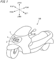
- the right and left direction refers to relative directions set to a vehicle 100 of FIG. 1 for convenience of descriptions.
- FIG. 1 depicts an automatic two-wheeled vehicle, which is an example of a vehicle 100 of the present embodiment.
- the automatic two-wheeled vehicle 100 is a vehicle capable of traveling around a corner (curve) of a road by tilting a vehicle body toward a turning direction.
- the vehicle of the present embodiment may be any vehicle capable of traveling around a corner by tilting a vehicle body toward a turning direction, like the automatic two-wheeled vehicle 100, and the number of wheels thereof is not limited. Therefore, for example, an automatic three-wheeled vehicle, an automatic four-wheeled vehicle and the like are also included in the vehicle of the present embodiment, inasmuch as they can travel in the same manner as the automatic two-wheeled vehicle 100.
- the automatic two-wheeled vehicle 100 is mounted on its front part with a headlamp 1 (an example of a vehicle lamp) capable of illuminating a region ahead of the vehicle.
- the headlamp 1 includes a low beam lamp unit 2, and a high beam lamp unit 3.
- the automatic two-wheeled vehicle 100 having one headlamp 1 is exemplified.
- an automatic two-wheeled vehicle having headlamps at both left and right sides is also possible.
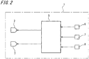
- the headlamp 1 includes a lamp control unit 5 configured to control operations of the low beam lamp unit 2 and the high beam lamp unit 3.
- the lamp control unit 5 is connected with the low beam lamp unit 2 and the high beam lamp unit 3, and is also connected with a bank angle sensor 6 (an example of a sensor) configured to detect a tilted state of the automatic two-wheeled vehicle 100 and an external sensor 7 (an example of a sensor) configured to detect environment information outside the vehicle.
- the lamp control unit 5 is connected with a speed sensor 8 for detecting a speed of the automatic two-wheeled vehicle 100, and the like.
- the bank angle sensor 6 is a sensor capable of detecting a tilt angle when the vehicle body of the automatic two-wheeled vehicle 100 is tilted leftward or rightward with respect to a vertical line.
- the bank angle sensor 6 is, for example, a gyro sensor.
- the tilt angle of the vehicle body may be calculated on the basis of an image captured by a camera mounted on the vehicle body of the automatic two-wheeled vehicle 100.
- the external sensor 7 is a sensor capable of acquiring information outside a host vehicle, including surrounding environments of the automatic two-wheeled vehicle 100 (for example, an obstacle, other vehicles (a preceding traveling vehicle, and an oncoming vehicle), a pedestrian, a road shape, a traffic mark, and the like).
- the external sensor 7 is configured by at least one of a LiDAR (Light Detection and Ranging or Laser Imaging Detection and Ranging), a camera, a radar and the like, for example.
- a LiDAR Light Detection and Ranging or Laser Imaging Detection and Ranging
- the lamp control unit 5 is configured to control operations of the low beam lamp unit 2 and the high beam lamp unit 3, based on the information transmitted from the respective sensors 6 to 8. For example, the lamp control unit 5 can adjust light distribution patterns (a low beam light distribution pattern and a high beam light distribution pattern) to be formed in a region ahead of the vehicle by controlling the headlamp 1 (the low beam lamp unit 2 and the high beam lamp unit 3), based on the detection information from the respective sensors.
- light distribution patterns a low beam light distribution pattern and a high beam light distribution pattern
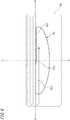
- FIG. 3 is a vertical sectional view depicting a schematic configuration of the low beam lamp unit 2 provided to the headlamp 1 in accordance with a first embodiment.
- the headlamp 1 includes a lamp body 11 having an opening on a front side of the vehicle, and a transparent front cover 12 attached to cover the opening of the lamp body 11.
- the low beam lamp unit 2 the lamp control unit 5, the bank angle sensor 6, the external sensor (for example LiDAR) 7 and the like are accommodated.
- the high beam lamp unit 3 is also accommodated in the lamp chamber 13 of the headlamp 1, as shown in FIG. 10 .
- the low beam lamp unit 2 includes a light source unit 20, and a light distribution unit 30 (an example of an optical member) configured to reflect light from the light source unit 20.
- the light source unit 20 and the light distribution unit 30 are supported in predetermined positions in the lamp chamber 13 by a support plate 41.
- the support plate 41 is attached to the lamp body 11 via an aiming screw 42.
- the light source unit 20 includes a plurality of (three, in the first example) light sources 21, a heat sink 22, a plurality of (four, in the first example) lenses 23, and a light condensing part 24.
- the light source unit 20 is fixed to a front surface of the support plate 41.
- Each of the light sources 21 is electrically connected to the lamp control unit 5.
- the light distribution unit 30 has a terminal part 37, and a reflecting mirror 38.
- the light distribution unit 30 is positionally determined with respect to the light source unit 20 so that the laser light emitted from the light source unit 20 can be reflected ahead of the low beam lamp unit 2 via the reflecting mirror 38.
- the light distribution unit 30 is fixed to a tip end of a protrusion 43 protruding forward from a front surface of the support plate 41.
- the terminal part 37 is electrically connected to the lamp control unit 5.
- the lamp control unit 5 is fixed to the lamp body 11 at the rear of the support plate 41. In the meantime, the position in which the lamp control unit 5 is provided is not limited thereto.
- the low beam lamp unit 2 is configured to adjust an optical axis in the horizontal direction and in the vertical direction by rotating the aiming screw 42 to adjust a posture of the support plate 41.
- FIG. 4 is a side view of the light source unit 20 configuring the low beam lamp unit 2.
- the light source unit 20 includes a first light source 21a, a second light source 21b, a third light source 21c, the heat sink 22, a first lens 23a, a second lens 23b, a third lens 23c, a fourth lens 23d, and the light condensing part 24.
- the first light source 21a is a light source configured to emit red laser light R, and is configured by a light-emitting element consisting of a red laser diode.
- the second light source 21b is configured by a green laser diode configured to emit green laser light G
- the third light source 21c is configured by a blue laser diode configured to emit blue laser light B.
- the first light source 21a, the second light source 21b, and the third light source 21c are disposed so that a laser light emission surface 25a, a laser light emission surface 25b, and a laser light emission surface 25c, which are light emission surfaces thereof, are parallel to each other.
- the light-emitting element of each light source is not limited to the laser diode.
- the first light source 21a to the third light source 21c are disposed so that the laser light emission surfaces 25a to 25c are to face ahead of the low beam lamp unit 2, and are attached to the heat sink 22.
- the heat sink 22 is formed of a material having high heat conductivity such as aluminum, and is attached to the light source unit 20 in a state in which a rear surface of the heat sink 22 is in contact with the support plate 41 (refer to FIG. 3 ).
- the first lens 23a to the fourth lens 23d are respectively configured by a collimate lens, for example.
- the first lens 23a is provided on a light path of the red laser light R between the first light source 21a and the light condensing part 24, and is configured to convert the red laser light R emitted from the first light source 21a into parallel light and to emit the same to the light condensing part 24.
- the second lens 23b is provided on a light path of the green laser light G between the second light source 21b and the light condensing part 24, and is configured to convert the green laser light G emitted from the second light source 21b into parallel light and to emit the same to the light condensing part 24.
- the third lens 23c is provided on a light path of the blue laser light B between the third light source 21c and the light condensing part 24, and is configured to convert the blue laser light B emitted from the third light source 21c into parallel light and to emit the same to the light condensing part 24.
- the fourth lens 23d is fitted in an opening provided at an upper part of a housing 26 of the light source unit 20.
- the fourth lens 23d is provided on a light path of white laser light W (which will be described later) between the light condensing part 24 and the light distribution unit 30 (refer to FIG.3 ), and is configured to convert the white laser light W emitted from the light condensing part 24 into parallel light and to emit the same to the light distribution unit 30.
- the light condensing part 24 is configured to condense the red laser light R, the green laser light G and the blue laser light B, thereby generating the white laser light W.
- the light condensing part 24 includes a first dichroic mirror 24a, a second dichroic mirror 24b, and a third dichroic mirror 24c.
- the first dichroic mirror 24a is a mirror for reflecting at least the red light and causing the blue light and the green light to transmit therethrough, and is disposed to reflect the red laser light R having transmitted the first lens 23a toward the fourth lens 23d.
- the second dichroic mirror 24b is a mirror for reflecting at least the green light and causing the blue light to transmit therethrough, and is disposed to reflect the green laser light G having transmitted the second lens 23b toward the fourth lens 23d.
- the third dichroic mirror 24c is a mirror for reflecting at least the blue light, and is disposed to reflect the blue laser light B having transmitted the third lens 23c toward the fourth lens 23d.
- the first dichroic mirror 24a to the third dichroic mirror 24c are positionally determined with respect to each other so that the light paths of the laser lights reflected by the mirrors are to be parallel and the respective laser lights are to be condensed and to be incident on the fourth lens 23d.
- the first dichroic mirror 24a to the third dichroic mirror 24c are disposed so that regions (reflecting points of the laser lights), with which the laser lights are to collide, of the respective dichroic mirrors 24a to 24c are aligned side by side on a line.
- the blue laser light B emitted from the third light source 21c is reflected by the third dichroic mirror 24c, and then travels toward the second dichroic mirror 24b.
- the green laser light G emitted from the second light source 21b is reflected toward the first dichroic mirror 24a by the second dichroic mirror 24b, and is superimposed on the blue laser light B having transmitted the second dichroic mirror 24b.
- the red laser light R emitted from the first light source 21a is reflected toward the fourth lens 23d by the first dichroic mirror 24a, and is superimposed on the aggregate light of the blue laser light B and green laser light G having transmitted the first dichroic mirror 24a.
- the white laser light W is formed, and the formed white laser light W travels toward the light distribution unit 30 through the fourth lens 23d.
- the first light source 21a configured to emit the red laser light R is disposed in a position closest from the light condensing part 24
- the third light source 21c configured to emit the blue laser light B is disposed in a position most distant from the light condensing part 24
- the second light source 21b configured to emit the green laser light G is disposed in an intermediate position. That is, the first light source 21a to the third light source 21c are disposed closer to the light condensing part 24 as the wavelength of the laser light emitted therefrom is longer.
- FIG. 5 is a perspective view depicting the light distribution unit 30 configuring the low beam lamp unit 2, as observed from the front.
- the light distribution unit 30 includes a base 31, a first rotating body 32, a second rotating body 33, a first torsion bar 34, a second torsion bar 35, permanent magnets 36a and 36b, the terminal part 37, and the reflecting mirror 38.
- the light distribution unit 30 is configured by a Galvano mirror, for example.
- the light distribution unit 30 may be configured by a MEMS mirror or a polygon mirror, for example.
- the base 31 is a frame body having an opening 31a formed at a center thereof, and is fixed to the protrusion 43 (refer to FIG. 3 ) with being inclined in the front and rear direction of the low beam lamp unit 2.
- the first rotating body 32 is disposed in the opening 31a of the base 31.
- the first rotating body 32 is a frame body having an opening 32a formed at a center thereof.
- the first rotating body 32 is supported to the base 31 so as to be rotatable in the right and left direction (vehicle width direction) by the first torsion bar 34 extending in a front and upper direction from a rear and lower side of the low beam lamp unit 2.
- the second rotating body 33 is disposed in the opening 32a of the first rotating body 32.
- the second rotating body 33 is a rectangular flat plate.
- the second rotating body 33 is supported to the first rotating body 32 so as to be rotatable in the upper and lower direction (vertical direction) by the second torsion bar 35 extending in the vehicle width direction of the automatic two-wheeled vehicle 100.
- the first rotating body 32 is rotated in the right and left direction about the first torsion bar 34, which is a rotational shaft, the second rotating body 33 is rotated in the right and left direction together with the first rotating body 32.
- a surface of the second rotating body 33 is provided with the reflecting mirror 38 by plating, vapor deposition or the like.
- the base 31 is provided with a pair of permanent magnets 36a in positions perpendicular to the extension direction of the first torsion bar 34.
- the permanent magnets 36a form a magnetic field perpendicular to the first torsion bar 34.
- the first rotating body 32 is wired thereon with a first coil (not shown). The first coil is connected to the lamp control unit 5 via the terminal part 37.
- the base 31 is provided with a pair of permanent magnets 36b in positions perpendicular to the extension direction of the second torsion bar 35.
- the permanent magnets 36b form a magnetic field perpendicular to the second torsion bar 35.
- the second rotating body 33 is wired thereon with a second coil (not shown). The second coil is connected to the lamp control unit 5 via the terminal part 37.
- Magnitudes and directions of currents flowing through the first coil and the second coil are controlled, so that the first rotating body 32 and the second rotating body 33 are reciprocally rotated in the right and left direction and the second rotating body 33 is independently reciprocally rotated in the upper and lower direction.
- the reflecting mirror 38 is reciprocally rotated in the upper and lower direction and the right and left direction.
- the light source unit 20 and the light distribution unit 30 are positionally determined with respect to each other so that the white laser light W emitted from the light source unit 20 is to be reflected ahead of the low beam lamp unit 2 by the reflecting mirror 38.
- the light distribution unit 30 is configured to scan a region ahead of the automatic two-wheeled vehicle 100 with the white laser light W by the reciprocal rotation of the reflecting mirror 38. For example, the light distribution unit 30 scans a formation region of a low beam light distribution pattern by the white laser light W. Thereby, the white laser light W is light-distributed in the formation region of the low beam light distribution pattern, so that a predetermined low beam light distribution pattern is formed ahead of the automatic two-wheeled vehicle 100.
- FIG. 6 depicts an example of the low beam light distribution pattern to be formed by the low beam lamp unit 2 in accordance with the first embodiment. Meanwhile, FIG. 6 depicts a low beam light distribution pattern formed on a virtual vertical screen disposed in a predetermined position ahead of the lamp, for example, in a position 25m ahead of the lamp. In the meantime, a line H-H indicates the horizontal direction, and a line V-V indicates the vertical direction.
- the light distribution unit 30 of the low beam lamp unit 2 in accordance with the first embodiment can scan a rectangular scanning region SA extending in the vehicle width direction by the white laser light W.
- the lamp control unit 5 controls each of the light sources 21 to emit the laser light from each of the light sources 21 when a scanning position of the light distribution unit 30 is within a low beam light distribution pattern PL.
- the lamp control unit 5 controls each of the light sources 21 to stop the emission of the laser light from each of the light sources 21.
- the low beam light distribution pattern PL having an opposite traffic line-side cutoff line CL1, a host traffic line-side cutoff line CL2 and an oblique cutoff line CL3 is formed.
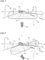
- FIG. 7 depicts a situation in which the automatic two-wheeled vehicle 100 travels on a host traffic lane C of a road having the host traffic lane C and an opposite traffic lane D.
- FV indicates a preceding traveling vehicle.
- FIG. 7 depicts a low beam light distribution pattern PL that is formed ahead of the lamp by the low beam lamp unit 2 in a state in which the vehicle body of the automatic two-wheeled vehicle 100 is not tilted.
- FIG. 8 depicts a low beam light distribution pattern PL1 that is formed ahead of the lamp by a low beam lamp unit (a low beam lamp unit of the related art) having no function of adjusting the low beam light distribution pattern in a state in which the vehicle body of the automatic two-wheeled vehicle 100 is tilted leftward.
- FIG. 9 depicts a low beam light distribution pattern PL2 that is formed ahead of the lamp by the low beam lamp unit 2 of the first embodiment in the state in which the vehicle body of the automatic two-wheeled vehicle 100 is tilted leftward.
- the white laser light W irradiated from the low beam lamp unit 2 is irradiated ahead of the lamp as the low beam light distribution pattern PL having such a shape that the opposite traffic line-side cutoff line CL1 and the host traffic line-side cutoff line CL2 are formed along the horizontal direction H.
- the irradiated white laser light W is irradiated ahead of the lamp as a low beam light distribution pattern PL1 having such a shape that the opposite traffic line-side cutoff line CL1 and the host traffic line-side cutoff line CL2 are tilted with respect to the horizontal direction H (tilted according to the tilted state of the automatic two-wheeled vehicle 100).
- the irradiated white laser light W is irradiated ahead of the lamp as a low beam light distribution pattern PL2 having such a shape that the opposite traffic line-side cutoff line CL1 and the host traffic line-side cutoff line CL2 are formed along the horizontal direction H.
- the shape of the low beam light distribution pattern PL2 which is formed by controlling the scanning direction of the Galvano mirror, which is the light distribution unit 30, and the emission timing of the laser light from each of the light sources 21, is adjusted to maintain the opposite traffic line-side cutoff line CL1 and the host traffic line-side cutoff line CL2 along the horizontal direction H according to the tilted state of the automatic two-wheeled vehicle 100 by the lamp control unit 5.
- the lamp control unit 5 acquires the tilt angle information of the vehicle body of the automatic two-wheeled vehicle 100, which is detected by the bank angle sensor 6, from the bank angle sensor 6.
- the lamp control unit 5 calculates tilt angles of the cutoff lines CL1 and CL2 of the low beam light distribution pattern PL1 when formed without correction, based on the tilt angle information of the vehicle body, and also calculates a tilt correction amount necessary to correct the tilt angles.
- the lamp control unit 5 determines, based on the calculated tilt correction amount, a corrected low beam light distribution pattern of which a shape has been already corrected, so as to set the low beam light distribution pattern, which is to be formed ahead of the lamp, as a low beam light distribution pattern PL2 of which the cutoff lines CL1 and CL2 are maintained along the horizontal direction H.
- the lamp control unit 5 generates a control signal for forming the corrected low beam light distribution pattern, and transmits the same to the light distribution unit 30 and each of the light sources 21 (21a to 21c).
- the light distribution unit 30 and each of the light sources 21 (21a to 21c) form the corrected low beam light distribution pattern, based on the control signal.
- a low beam light distribution pattern (the corrected low beam light distribution pattern) PL2 in which the opposite traffic line-side cutoff line CL1 and the host traffic line-side cutoff line CL2 are maintained along the horizontal direction H is formed ahead of the lamp.
- the lamp control unit 5 adjusts so that no light from each of the light sources 21 is not irradiated to a region located outside the low beam light distribution pattern PL corresponding to when the vehicle body is in the vertical state. In this way, even when the automatic two-wheeled vehicle 100 travels with the vehicle body being tilted, it is possible to maintain the low beam light distribution pattern having a shape corresponding to the shape of the low beam light distribution pattern PL (refer to FIG. 7 ) that is formed ahead of the lamp when the vehicle body is not tilted (in the vertical state).
- the headlamp 1 having the low beam lamp unit 2 configured as described above includes the light source 21, the light distribution unit 30 configured to form the predetermined low beam light distribution pattern PL by irradiating the light from the light source 21 toward the region ahead of the lamp, and the lamp control unit 5 configured to adjust the low beam light distribution pattern PL according to the tilted state of the vehicle body of the automatic two-wheeled vehicle 100.
- the lamp control unit 5 is configured to adjust the low beam light distribution pattern PL2 so that in the low beam light distribution pattern PL2 corresponding to when the vehicle body is tilted, no light from the light source 21 is irradiated to the region located outside the low beam light distribution pattern PL corresponding to when the vehicle body is in the vertical state.
- the lamp control unit 5 adjusts the low beam light distribution pattern PL2 so that the cutoff lines CL1 and CL2 are maintained along the horizontal direction H. Thereby, upon the bank of the vehicle body, it is possible to maintain the low beam light distribution pattern PL2 at an appropriate angle, which can contribute to improvements on safety in assisting the driving, for example.
- the lamp control unit 5 is configured to adjust the low beam light distribution pattern PL by controlling the light scanning direction by the light distribution unit 30 consisting of the Galvano mirror, for example. Thereby, it is possible to easily adjust the low beam light distribution pattern PL.
- the headlamp 1 since the headlamp 1 includes the bank angle sensor 6, it is possible to correctly detect the tilted state of the vehicle body. For this reason, it is possible to appropriately reflect the detected tilt information in the formation of the low beam light distribution pattern PL.
- the headlamp 1 since the headlamp 1 includes the external sensor 7, it is possible to appropriately reflect the environment information around the vehicle in the formation of the low beam light distribution pattern PL.
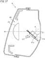
- the high beam lamp unit 3 is a so-called projector-type lamp, and includes a projector lens 112, a light source unit 114 having a light source 116 for high beam irradiation, and a holder 118 configured to hold the projector lens 112 and the light source unit 114.
- the projector lens 112 is a plano-convex aspherical lens of which a front surface is a convex surface and a rear surface is a planar surface, and is disposed on an optical axis Ax extending in the front and rear direction of the vehicle.
- the projector lens 112 is held at a peripheral edge portion by a front end side of the holder 118.
- the light source unit 114 is held on a rear end side of the holder 118 with the light source 116 being disposed toward the front in the direction of the optical axis Ax.
- the light source unit 114 of the first embodiment is configured as an LED array, for example.
- the holder 118 is attached to the lamp body 11 via a support member (not shown).
- the structure of the high beam lamp unit 3 is not particularly limited to the above, and may be a reflection-type lamp, as with the low beam lamp unit 2.
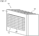
- FIG. 11 is a perspective view depicting a schematic structure of the light source unit 114.
- the light source unit 114 includes a light source 116, a support plate 130, and a heat sink 132.
- the light source 116 has a plurality of individual light sources 120 each of which consists of a light-emitting element such as a light-emitting diode (LED), for example.
- the individual light sources 120 are disposed adjacent to each other in 12 columns and 8 rows, for example, and are fixed on a front surface of the support plate 130.
- the light irradiations of the plurality of individual light sources 120 are independently controlled in an ADB mode by the lamp control unit 5, which will be described later.
- the numbers and arrangement of the individual light sources are not particularly limited. Also, one individual light source may be formed by the plurality of light-emitting elements.
- the heat sink 132 is a member for radiating heat from the light source 116, and is held on a surface of the support plate 130 facing toward the rear of the vehicle.
- the light source unit 114 is fixed to the holder 118 via the support plate 130.
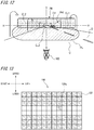
- FIG. 12 pictorially depicts a low beam light distribution pattern and a high beam light distribution pattern to be formed by the vehicle lamp.
- FIG. 12 depicts the light distribution patterns formed on a virtual vertical screen arranged in a predetermined position ahead of the lamp, for example, in a position 25m ahead of the lamp.
- a high beam light distribution pattern PH is formed by irradiation light of the high beam lamp unit 3.
- the high beam light distribution pattern PH is a light distribution pattern formed in addition to the low beam light distribution pattern PL.
- the high beam light distribution pattern PH is added to the low beam light distribution pattern PL so that an irradiation region is to be formed at least above the opposite traffic line-side cutoff line CL1 of the low beam light distribution pattern PL.
- the high beam light distribution pattern PH is a light distribution pattern formed as a result of synthesis of partial patterns formed by each of the plurality of individual light sources 120.
- the high beam lamp unit 3 can form a plurality of additional light distribution patterns having different shapes by combinations of formation and non-formation of the respective partial patterns in an ADB mode (which will be described later), in correspondence to a situation of the host vehicle or the preceding vehicle.
- the lamp control unit 5 can detect situations of the preceding vehicle, including presence or absence and a presence position of the preceding vehicle, based on the environment information acquired by the external sensor 7 mounted on the automatic two-wheeled vehicle 100, for example.
- the external sensor 7 is configured to transmit a detection result of the environment information to the lamp control unit 5.
- the lamp control unit 5 can detect situations of the host vehicle, including traveling and stop of the host vehicle, based on the information acquired by the speed sensor 8 mounted on the automatic two-wheeled vehicle 100, for example.
- the lamp control unit 5 When the lamp control unit 5 acquires the information from the external sensor 7 and/or the speed sensor 8, the lamp control unit controls individually the lighting/lights-out of the individual light sources 120, based on the information input from the outside. Specifically, the lamp control unit 5 is configured to control the lighting/lights-out of each of the individual light sources 120 so that the individual light sources 120, which are in a region to be used for formation of the high beam light distribution pattern PH, of the plurality of the individual light sources 120 are to be turned on and the individual light sources 120, which are in a region not to be used for formation of the high beam light distribution pattern PH, are to be turned off. Also, the lamp control unit 5 is configured to turn off the individual light source 21 corresponding to a region in which there is a target object such as a preceding vehicle.
- the lamp control unit 5 turns off the individual light sources 120 in the upper and lower three rows of the plurality of the individual light sources 120, and turns on the individual light sources 120 in the central two lines. Also, the lamp control unit 5 determines a region in which there is a target object such as a preceding vehicle, as a non-irradiation region (light shielding region), and turns off the individual light source 120 corresponding to the non-irradiation region, for example, the individual light source 120a (the individual light source at the fifth light source from the right in the upper row of the individual light sources 120 in the central two rows) corresponding to a region in which there is an oncoming vehicle CV of FIG. 12 .
- a target object such as a preceding vehicle
- the "non-irradiation region” may include a region in which light is to be irradiated with a low illuminance at which the glare is not to be provided to a driver of the preceding vehicle.
- the automatic two-wheeled vehicle 100 tilts the vehicle body leftward with respect to the road surface, for example, travels with tilting the vehicle body leftward so as to move to the left of the road
- the positions of the individual light sources 120 in the lighting state and the individual light sources 120 in the lights-out state of the plurality of individual light sources 120 are fixed, the light irradiated from the high beam lamp unit 3 is formed ahead of the lamp, as the high beam light distribution pattern PH2 tilted with respect to the horizontal direction H according to the tilted state of the automatic two-wheeled vehicle 100.
- an amount of light becomes insufficient and far visibility is lowered in a region in front of the automatic two-wheeled vehicle 100, particularly, on a side in the turning direction, in some cases. Also, at least a part of the region in which there is the oncoming vehicle CV deviates from the non-irradiation region PH1 (i.e., is included in the irradiation region), so that the glare may be provided to the driver of the oncoming vehicle CV.
- the lamp control unit 5 controls the lighting/lights-out of the respective individual light sources 120 of the high beam lamp unit 3 so that a light distribution pattern having such a shape that a longitudinal direction of the high beam light distribution pattern PH is substantially along the horizontal direction H is to be formed ahead of the lamp.
- the lamp control unit 5 controls the lighting/lights-out of the individual light sources 120 so that the longitudinal direction of the high beam light distribution pattern PH is substantially along the horizontal direction H.
- the positions of the individual light sources 120, which are to be turned on so as to form the high beam light distribution pattern PH, of the plurality of individual light sources 120 aligned as an LED array can be appropriately changed according to the tilted state of the automatic two-wheeled vehicle 100.
- the lamp control unit 5 is configured to control the lighting/lights-out of the respective individual light sources 120 so that the non-irradiation region PH1 continues to be arranged in a part corresponding to the oncoming vehicle CV. Specifically, as shown in FIG. 15 , the lamp control unit 5 turns off the individual light sources 120b, which correspond to a position in which there is the oncoming vehicle CV, of the individual light sources 120. That is, the positions of the individual light sources 120b, which are to be turned off in correspondence to the position of the oncoming vehicle CV, can be appropriately changed according to the tilted state and speed of the automatic two-wheeled vehicle 100 and the current position of the oncoming vehicle CV.
- the headlamp 1 having the high beam lamp unit 3 configured as described above includes the light source 116, the projector lens 112 configured to form a predetermined high beam light distribution pattern PH by irradiating the light emitted from the light source 116 toward a region ahead of the lamp, and the lamp control unit 5 configured to adjust the high beam light distribution pattern PH according to the tilted state of the vehicle body of the automatic two-wheeled vehicle 100.
- the lamp control unit 5 is configured to adjust the high beam light distribution pattern PH so that in the high beam light distribution pattern PH1 corresponding to when the vehicle body is tilted, no light is irradiated in a region located outside the high beam light distribution pattern PH corresponding to when the vehicle body is in the vertical state.
- the lamp control unit 5 is configured to adjust the lighting/lights-out of the individual light sources 120 so that even when the automatic two-wheeled vehicle 100 is tilted, the longitudinal direction of the high beam light distribution pattern PH is substantially along the horizontal direction H. Thereby, even when the automatic two-wheeled vehicle 100 travels with being tilted leftward or rightward, the appropriate high beam light distribution pattern PH can be formed, which can contribute to improvement on safety in assisting the driving, for example.
- the lamp control unit 5 adjusts the high beam light distribution pattern PH so that the non-irradiation region PH1 continues to be arranged in a part corresponding to the position in which there is the oncoming vehicle CV.
- the lamp control unit 5 adjusts the high beam light distribution pattern PH so that the non-irradiation region PH1 continues to be arranged in a part corresponding to the position in which there is the oncoming vehicle CV.
- the light source 116 includes the plurality of individual light sources 120 aligned in parallel, and the lamp control unit 5 is configured to adjust the high beam light distribution pattern PH by controlling the lighting/lights-out of the plurality of individual light sources 120. Thereby, it is possible to easily adjust the high beam light distribution pattern PH.
- the lamp control unit 5 adjusts the lighting/lights-out pattern of the individual light sources 120 so that the cutoff line is maintained along the horizontal direction.
- a high beam lamp unit 203 of a headlamp 1A includes a rotary reflector 211 (an example of an optical member), an LED 213 (an example of a light source), and a projector lens 215 disposed in front of the rotary reflector 211.
- a semiconductor light-emitting element such as an EL element and an LD element can be used as the light source.
- a light source capable of performing lighting/lights-out in a short time with accuracy is preferably used.
- a shape of the projector lens 215 may be appropriately selected according to a required light distribution pattern and a light distribution characteristic such as an illuminance distribution.
- an aspherical lens or a free-form surface lens is used.
- a convex aspherical lens is used as the projector lens 215, for example.
- the rotary reflector 211 is configured to rotate in one direction about a rotation axis R by a drive source such as a motor (not shown). Also, the rotary reflector 211 has a reflecting surface configured to reflect light emitted from the LED 213 while rotating, and to form a desired light distribution pattern.
- the rotary reflector 211 has three blades 211a having the same shape, and a tubular rotating part 211b.
- the blades 211a function as the reflecting surface, and are provided around the rotating part 211b.
- the rotation axis R of the rotary reflector 211 is oblique with respect to the optical axis Ax, and is provided in a plane including the optical axis Ax and the LED 213.
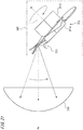
- the blade 211a has such a distorted shape that an angle between the optical axis Ax and the reflecting surface changes toward a circumferential direction about the rotation axis R. Thereby, as shown in FIG. 18 , the scanning of using the light emitted from the LED 213 is possible.
- the rotary reflector 211 is configured to scan once the front in one direction (horizontal direction) by the light emitted from the LED 213 through rotation of 120°. That is, when one blade 211a passes in front of the LED 213, a desired region ahead of the vehicle is scanned once by the light emitted from the LED 213.
- the timing of the lighting/lights-out of the LED 213 and the change in degree of light emission are synchronized with the rotation of the rotary reflector 211, so that it is possible to form a high beam light distribution pattern in which any region (for example, the non-irradiation region PH1 of FIG 12 ) is light-shielded, like the high beam light distribution pattern PH shown in FIG. 12 .
- the high beam lamp unit 203 can perform control of swiveling the high beam light distribution pattern when synchronizing the timing of the lighting/lights-out of the LED 213 with the rotation of the rotary reflector 211. Therefore, even when the vehicle body of the automatic two-wheeled vehicle 100 is tilted, the synchronization processing of the timing of the lighting/lights-out of the LED 213 and the rotation of the rotary reflector 211 is adjusted so that the longitudinal direction of the light distribution pattern is maintained along the horizontal direction.
- the high beam light distribution pattern can be adjusted so that no light is irradiated in a region located outside the high beam light distribution pattern corresponding to when the vehicle body is in the vertical state. Also, even when the vehicle body is tilted, the high beam light distribution pattern can be adjusted so that the non-irradiation region continues to be arranged in a part corresponding to a region in which there is a target object.
- FIG. 19 is a vertical sectional view depicting a schematic configuration of a low beam lamp unit 302 provided to a headlamp 1B in accordance with a third embodiment.
- the headlamp 1B includes a lamp body 11 having an opening on a front side of the vehicle, and a transparent front cover 12 attached to cover the opening of the lamp body 11.
- the low beam lamp unit 302 the lamp control unit 5, the bank angle sensor 6, the external sensor (for example LiDAR) 7 and the like are accommodated.
- a high beam lamp unit 303 is also accommodated in the lamp chamber 13 of the headlamp 1B, like the low beam lamp unit 302, as shown in FIG. 20 .
- the low beam lamp unit 302 is a so-called projector-type lamp, and includes a light source unit 20, a light distribution unit 30 (an example of an optical member) configured to reflect light from the light source unit 20, and a projector lens 50.
- the light source unit 20, the light distribution unit 30 and the projector lens 50 are supported in predetermined positions in the lamp chamber 13 by a support plate 41.
- the support plate 41 is attached to the lamp body 11 via an aiming screw 42.
- the light source unit 20 includes a plurality of (three, in the third embodiment) light sources 21, a heat sink 22, a plurality of (four, in the third embodiment) lenses 23, and a light condensing part 24.
- the light source unit 20 is fixed on a front surface of the support plate 41.
- Each of the light sources 21 is electrically connected to the lamp control unit 5.
- the light distribution unit 30 includes a terminal part 37, and a reflecting mirror 38 (an example of a reflecting body).
- the light distribution unit 30 is positionally determined with respect to the light source unit 20 so that the laser light emitted from the light source unit 20 can be reflected ahead of the low beam lamp unit 302 via the reflecting mirror 38.
- the light distribution unit 30 is fixed to a protrusion 43 protruding forward from a front surface of the support plate 41 via an actuator 45 (an example of a correction mechanism), which will be described later.
- the terminal part 37 is electrically connected to the lamp control unit 5.
- the projector lens 50 is a plano-convex aspherical lens of which a front surface is a convex surface and a rear surface is a planar surface, and is disposed on the optical axis Ax extending in the front and rear direction of the vehicle.
- the projector lens 50 is fixed to a tip end of the protrusion 43 of the support plate 41.
- the low beam lamp unit 302 is configured to be able to adjust the optical axis Ax in the horizontal direction and the vertical direction by rotating the aiming screw 42 to adjust a posture of the support plate 41.
- the actuator 45 is a device for adjusting postures of the light distribution unit 30 and projector lens 50 of the low beam lamp unit 302.
- the actuator 45 is configured as a so-called biaxial actuator configured to drive the light distribution unit 30 and the projector lens 50 around two orthogonal axes.
- the actuator 45 is configured to change the postures of the light distribution unit 30 and the projector lens 5 in a horizontal plane (in a plane including the front and rear direction and the right and left direction) and in a vertical plane (in a plane including the right and left direction and the upper and lower direction). Since the configuration of the biaxial actuator is well known, the detailed description thereof is omitted.
- the actuator 45 may be configured as a uniaxial actuator configured to drive the light distribution unit 30 and the projector lens 50 around one axis along the front and rear direction.
- the lamp control unit 5 is fixed to the lamp body 11 at the rear of the support plate 41. In the meantime, the position in which the lamp control unit 5 is provided is not limited thereto.
- the lamp control unit 5 is configured to acquire, from the bank angle sensor 6, information (hereinbelow, referred to as 'bank angle information') about a tilted angle of the vehicle body of the automatic two-wheeled vehicle 100 detected by the bank angle sensor 6. Specifically, the lamp control unit 5 is configured to generate a bank angle signal S1 based on a signal associated with the bank angle information during the traveling of the automatic two-wheeled vehicle 100, which is output from the bank angle sensor 6, and to input the generated signal to the actuator 45.
- the bank angle signal S1 has attributes (a voltage value, a current value, a frequency and the like) corresponding to an amount of adjustment of the posture of the automatic two-wheeled vehicle 100 in the vertical plane, which is detected by the bank angle sensor 6.
- the actuator 45 is configured to adjust the postures of the light distribution unit 30 and the projector lens 50 in the vertical plane, based on the bank angle signal S1. That is, in the low beam lamp unit 302 of the third embodiment, the adjustment of the postures (tilts in the vertical plane) of the light distribution unit 30 and the projector lens 50 by the actuator 45 is performed on the basis of the detection of the bank angle information by the bank angle sensor 6.
- the light source unit 20 and the light distribution unit 30 are positionally determined with respect to each other so that the white laser light W emitted from the light source unit 20 is to be reflected ahead of the low beam lamp unit 302 by the reflecting mirror 38.
- the light distribution unit 30 is configured to scan the front of the automatic two-wheeled vehicle 100 with the white laser light W by the reciprocal rotation of the reflecting mirror 38.
- the light distribution unit 30 is configured to scan a region of the low beam light distribution pattern to be formed by the white laser light W, via the projector lens 50. Thereby, the white laser light W is distributed in a formation region of the low beam light distribution pattern, so that a predetermined low beam light distribution pattern is formed ahead of the automatic two-wheeled vehicle 100.
- the light distribution unit 30 of the low beam lamp unit 302 in accordance with the third embodiment can scan a rectangular scanning region SA extending in the vehicle width direction by the white laser light W, via the projector lens 50.
- the lamp control unit 5 controls each of the light sources 21 so as to emit the laser light from each of the light sources 21.
- the lamp control unit 5 controls each of the light sources 2 so as to stop the emission of the laser light from each of the light sources 21.
- the white laser light W irradiated from the low beam lamp unit 302 is irradiated ahead of the lamp as the low beam light distribution pattern PL having such a shape that the opposite traffic line-side cutoff line CL1 and the host traffic line-side cutoff line CL2 are along the horizontal direction H.
- the irradiated white laser light W is irradiated ahead of the lamp as a low beam light distribution pattern PL1 having such a shape that the opposite traffic line-side cutoff line CL1 and the host traffic line-side cutoff line CL2 are tilted with respect to the horizontal direction H (tilted according to the tilted state of the automatic two-wheeled vehicle 100). For this reason, an amount of light becomes insufficient and far visibility is lowered on a side in the turning direction, in some cases.
- the lamp control unit 5 is configured to correct tilts (angles) of the light distribution unit 30 and the projector lens 50 in the vertical plane by the actuator 45 on the basis of the tilt signal S1 output from the bank angle sensor 6 so that the opposite traffic line-side cutoff line CL1 and the host traffic line-side cutoff line CL2 of the low beam light distribution pattern PL are maintained along the horizontal direction H.
- the lamp control unit 5 transmits the tilt signal S1 to the actuator 45, and controls the actuator 45 so as to tilt the light distribution unit 30 and the projector lens 50 in an opposite direction (for example, a right side) to the tilted direction of the automatic two-wheeled vehicle 100.
- the lamp control unit 5 transmits the tilt signal S1 to the actuator 45, and controls the actuator 45 so as to tilt the light distribution unit 30 and the projector lens 50 in an opposite direction (for example, a right side) to the tilted direction of the automatic two-wheeled vehicle 100.
- the irradiated white laser light W is irradiated ahead of the lamp as the low beam light distribution pattern PL2 having such a shape that the opposite traffic line-side cutoff line CL1 and the host traffic line-side cutoff line CL2 are along the horizontal direction H.
- the angles of the light distribution unit 30 and the projector lens 50 are corrected by the actuator 45, so that the low beam light distribution pattern PL2, which has a shape corresponding to a shape of the low beam light distribution pattern PL (refer to FIG. 7 ) formed ahead of the lamp in a state (the vertical state) in which the vehicle body is not tilted, can be maintained.
- the headlamp 1B having the low beam lamp unit 302 in accordance with the third embodiment includes the light source unit 20 (the light source 21), the light distribution unit 30 and projector lens 50 configured to form a predetermined light distribution pattern by irradiating the light from the light source 21 toward a region ahead of the lamp, and the actuator 45 configured to correct the angles of the light distribution unit 30 and the projector lens 50 according to the tilted state of the automatic two-wheeled vehicle 100.
- the low beam light distribution pattern PL2 can be maintained at the appropriate angle. For this reason, for example, it is possible to contribute to improvement on safety in assisting the driving.
- the actuator 45 is configured to rotate the light distribution unit 30 and the projector lens 50 in the vertical plane, (in the opposite direction to the tilt angle) in correspondence to the tilt angle of the automatic two-wheeled vehicle 100.
- the projector lens 50 is configured to rotate together with the light distribution unit 30.
- the present disclosure is not limited thereto.
- the projector lens 50 may be fixedly maintained in the lamp chamber 13, and only the light distribution unit 30 may be rotated by the actuator 45.
- the low beam lamp unit 302 may have a correction mechanism for correcting positions of the light distribution unit 30 and the projector lens 50, as an alternative to the actuator 45 configured to rotate the light distribution unit 30 and the projector lens 50 in the vertical plane.
- the correction mechanism may be configured to change relative positions of the light distribution unit 30 and the projector lens 50, for example.
- the description "to change relative positions" includes changing relative positions of the light distribution unit 30 and the projector lens 50 in the vertical plane including the right and left direction and the upper and lower direction.
- the relative positions of the light distribution unit 30 and the projector lens 50 may be changed so that, when the automatic two-wheeled vehicle 100 is tilted leftward or rightward, the light reflected on the light distribution unit 30 is to be mainly incident on the lower side of the projector lens 50.
- the light distribution unit 30 is moved downward with respect to the fixed projector lens 50.
- the low beam light distribution pattern may be formed on an upper side of the low beam light distribution pattern PL1 shown in FIG. 8 . According to this configuration, the sufficient amount of light can be maintained on a side toward which the automatic two-wheeled vehicle 100 turns, and the lowing in far visibility can be prevented.
- the high beam lamp unit 303 is a so-called projector-type lamp, and includes a rotary reflector 311 (an example of an optical member), an LED 313 (an example of a light source), a projector lens 315 (an example of an optical member) disposed in front of the rotary reflector 311, and an actuator 320.
- a semiconductor light-emitting element such as an EL element and an LD element can be used as the light source.
- a light source capable of performing lighting/lights-out in a short time with accuracy is preferably used.
- a shape of the projector lens 315 may be appropriately selected according to a required light distribution pattern and a light distribution characteristic such as an illuminance distribution.
- a light distribution characteristic such as an illuminance distribution.
- an aspherical lens or a free-form surface lens is used.
- a convex aspherical lens is used as the projector lens 315, for example.
- the actuator 320 is a device for adjusting a posture (particularly, a posture in the vertical plane) of the rotary reflector 311, like the actuator 45 of the low beam lamp unit 302.
- the rotary reflector 311 is configured to rotate in one direction about the rotation axis R by a drive source such as a motor (not shown). Also, the rotary reflector 311 has a reflecting surface configured to reflect light emitted from the LED 313 while rotating, and to form a desired light distribution pattern.
- the rotary reflector 311 has three blades 311a having the same shape, and a tubular rotating part 311b.
- the blades 311a function as the reflecting surface, and are provided around the rotating part 311b.
- the rotation axis R of the rotary reflector 311 is oblique with respect to the optical axis Ax, and is provided in a plane including the optical axis Ax and the LED 313.
- the blade 311a has such a distorted shape that an angle between the optical axis Ax and the reflecting surface changes toward a circumferential direction about the rotation axis R. Thereby, as shown in FIG. 21 , the scanning of using the light emitted from the LED 313 is possible.
- the rotary reflector 311 is configured to scan once the front in one direction (horizontal direction) by the light emitted from the LED 313 through rotation of 120°. That is, when one blade 311a passes in front of the LED 313, a desired region ahead of the vehicle is scanned once by the light emitted from the LED 313.
- the lamp control unit 5 is configured to generate a bank angle signal S1 based on a signal associated with the bank angle information during the traveling of the automatic two-wheeled vehicle 100, which is output from the bank angle sensor 6, and to input the generated signal to the actuator 320.
- the actuator 320 is configured to adjust a posture of the rotary reflector 311 in the vertical plane, based on the bank angle signal S1. That is, in the high beam lamp unit 303 of the third embodiment, the adjustment of the posture (tilt in the vertical plane) of the rotary reflector 311 by the actuator 320 is performed on the basis of the detection of the bank angle information by the bank angle sensor 6.
- FIG. 22 pictorially depicts a low beam light distribution pattern and a high beam light distribution pattern to be formed by the vehicle lamp.
- FIG. 12 depicts the light distribution patterns formed on a virtual vertical screen arranged in a predetermined position ahead of the lamp, for example, in a position 25m ahead of the lamp.
- a high beam light distribution pattern PH is formed by the irradiation light from the high beam lamp unit 303.
- the high beam light distribution pattern PH is a light distribution pattern formed additionally to the low beam light distribution pattern PL.
- the high beam light distribution pattern PH is added to the low beam light distribution pattern PL so that an irradiation region is to be formed at least above the opposite traffic line-side cutoff line CL1 of the low beam light distribution pattern PL.
- the lamp control unit 5 acquires the information from the external sensor 7 and/or the speed sensor 8, the lamp control unit synchronizes the timing of the lighting/lights-out of the LED 313 and the change in degree of light emission with the rotation of the rotary reflector 311, based on the information input from the outside.
- a high beam light distribution pattern PH in the ADB mode in which any region (for example, a non-irradiation region LS in FIG. 22 ) is set as a non-irradiation region can be formed.
- the lamp control unit 5 controls operations of the LED 313 and the rotary reflector 311 so as not to irradiate a region, in which there is a target object such as a preceding vehicle (for example, the preceding traveling vehicle FV).
- the "non-irradiation region LS" may include a region in which light is to be irradiated with a low illuminance at which the glare is not to be provided to a driver of the preceding vehicle.
- the automatic two-wheeled vehicle 100 tilts the vehicle body leftward with respect to the road surface, for example, travels with tilting the vehicle body leftward so as to move to the left of the road
- the angle of the rotary reflector 311 is fixed, the light irradiated from the high beam lamp unit 303 is formed ahead of the lamp, as a high beam light distribution pattern PH1 tilted with respect to the horizontal direction H according to the tilted state of the automatic two-wheeled vehicle 100.
- an amount of light becomes insufficient and far visibility is lowered in a region in front of the automatic two-wheeled vehicle 100, particularly, on a side in the turning direction of the automatic two-wheeled vehicle 100, in some cases.
- at least a part of the region in which there is the preceding traveling vehicle FV deviates from the non-irradiation region LS (i.e., is included in the irradiation region), so that the glare may be provided to the driver of the preceding traveling vehicle FV.
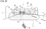
- the lamp control unit 5 is configured to correct the angle in the vertical plane of the rotary reflector 311 by the actuator 320. For example, even when the automatic two-wheeled vehicle 100 travels with tilting the vehicle body, as described above, the lamp control unit 5 corrects the angle of the rotary reflector 311 so that a light distribution pattern having such a shape that a longitudinal direction of the high beam light distribution pattern PH is substantially along the horizontal direction H is to be formed ahead of the lamp, as shown in FIG. 24 .
- the lamp control unit 5 transmits the tilt signal S1 to the actuator 320, and controls the actuator 320 so as to tilt the rotary reflector 311 in the opposite direction (for example, the right side) to the tilting direction of the automatic two-wheeled vehicle 100.
- the headlamp 1B having the high beam lamp unit 303 in accordance with the third embodiment includes the LED 313, the rotary reflector 311 and projector lens 315 configured to form the high beam light distribution pattern PH by irradiating the light emitted from the LED 313 toward the region ahead of the lamp, and the actuator 320 configured to correct the angle of the rotary reflector 311. For this reason, even when the automatic two-wheeled vehicle 100 travels with being tilted leftward or rightward, the angle of the rotary reflector 311 is corrected by the actuator 320, so that the appropriate high beam light distribution pattern PH can be formed. Thereby, for example, it is possible to contribute to improvement on safety in assisting the driving.
- the lamp control unit 5 is configured to correct the angle of the rotary reflector 311 by the actuator 320. Therefore, even when the vehicle body of the automatic two-wheeled vehicle 100 is tilted, the high beam light distribution pattern PH can be formed so that the non-irradiation region LS continues to be arranged in a part corresponding to a position in which there is the preceding vehicle such as the preceding traveling vehicle FV. Thereby, even upon the bank of the vehicle, the non-irradiation region LS of the high beam light distribution pattern PH can be maintained as appropriate, so that it is possible to prevent the glare to the drivers of the preceding traveling vehicle FV and the oncoming vehicle.
- the high beam lamp unit 303 may have a correction mechanism for correcting relative positions of the rotary reflector 311 and the projector lens 315, as an alternative to the actuator 320 configured to correct the angle of the rotary reflector 311.
- the correction mechanism changes the relative positions of the light distribution unit and the projector lens (for example, moves the rotary reflector downward with respect to the fixed projector lens) so that, when the automatic two-wheeled vehicle 100 is tilted leftward or rightward, for example, the light reflected on the rotary reflector is to be mainly incident on the lower side of the projector lens.
- the high beam light distribution pattern can be formed on the upper side of the high beam light distribution pattern PH1 shown in FIG. 23 .
- the lamp control unit 5, the bank angle sensor 6 and the external sensor 7 are accommodated in the lamp chamber of the headlamp.
- the present invention is not limited thereto.
- the lamp control unit 5, the bank angle sensor 6 and the external sensor 7 may be disposed as separate members from the headlamp.
- a projector lens which is similar to that of the low beam lamp unit 302 of the third embodiment, may be provided in front of the light distribution unit 30.
Landscapes
- Engineering & Computer Science (AREA)
- General Engineering & Computer Science (AREA)
- Mechanical Engineering (AREA)
- Lighting Device Outwards From Vehicle And Optical Signal (AREA)
- Non-Portable Lighting Devices Or Systems Thereof (AREA)
- Circuit Arrangement For Electric Light Sources In General (AREA)
- Arrangement Of Elements, Cooling, Sealing, Or The Like Of Lighting Devices (AREA)
Applications Claiming Priority (3)
| Application Number | Priority Date | Filing Date | Title |
|---|---|---|---|
| JP2017161188 | 2017-08-24 | ||
| JP2017161187 | 2017-08-24 | ||
| PCT/JP2018/022376 WO2019039051A1 (ja) | 2017-08-24 | 2018-06-12 | 車両用灯具 |
Publications (2)
| Publication Number | Publication Date |
|---|---|
| EP3674601A1 true EP3674601A1 (de) | 2020-07-01 |
| EP3674601A4 EP3674601A4 (de) | 2021-05-05 |
Family
ID=65440052
Family Applications (1)
| Application Number | Title | Priority Date | Filing Date |
|---|---|---|---|
| EP18849003.1A Withdrawn EP3674601A4 (de) | 2017-08-24 | 2018-06-12 | Fahrzeugbeleuchtungsvorrichtung |
Country Status (5)
| Country | Link |
|---|---|
| US (1) | US11254384B2 (de) |
| EP (1) | EP3674601A4 (de) |
| JP (1) | JPWO2019039051A1 (de) |
| CN (1) | CN111094840A (de) |
| WO (1) | WO2019039051A1 (de) |
Cited By (3)
| Publication number | Priority date | Publication date | Assignee | Title |
|---|---|---|---|---|
| EP3981674A4 (de) * | 2019-07-05 | 2022-08-03 | Yamaha Hatsudoki Kabushiki Kaisha | Scheinwerfervorrichtung und neigefahrzeug mit besagter scheinwerfervorrichtung |
| US12358586B2 (en) | 2020-10-21 | 2025-07-15 | Yamaha Hatsudoki Kabushiki Kaisha | Headlight device and leaning vehicle |
| US12403971B2 (en) | 2020-10-21 | 2025-09-02 | Yamaha Hatsudoki Kabushiki Kaisha | Headlight device and leaning vehicle |
Families Citing this family (11)
| Publication number | Priority date | Publication date | Assignee | Title |
|---|---|---|---|---|
| EP3859204A4 (de) * | 2018-09-28 | 2022-05-04 | Ichikoh Industries, Ltd. | Fahrzeuglampe |
| AT522637B1 (de) | 2019-05-29 | 2025-10-15 | Ktm Ag | Scheinwerfer mit Sensor |
| WO2021124778A1 (ja) * | 2019-12-16 | 2021-06-24 | 株式会社小糸製作所 | 車両用灯具 |
| CN114867653A (zh) * | 2019-12-16 | 2022-08-05 | 株式会社小糸制作所 | 车辆用灯具 |
| US12179655B2 (en) | 2020-01-16 | 2024-12-31 | Koito Manufacturing Co., Ltd. | Vehicle lamp |
| US12109934B2 (en) * | 2020-07-17 | 2024-10-08 | Koito Manufacturing Co., Ltd. | Vehicle system and vehicle lamp |
| JP7504733B2 (ja) * | 2020-09-14 | 2024-06-24 | 株式会社小糸製作所 | 車両用灯具および車両システム |
| WO2022185887A1 (ja) * | 2021-03-05 | 2022-09-09 | 株式会社小糸製作所 | 車両用灯具 |
| WO2023127428A1 (ja) * | 2021-12-27 | 2023-07-06 | 株式会社小糸製作所 | 配光制御装置および配光制御方法 |
| CN116101406B (zh) * | 2022-11-18 | 2023-11-14 | 思各异科技(广州)有限公司 | 两轮交通工具车灯光束控制方法、装置及系统 |
| CN120129117A (zh) * | 2023-12-08 | 2025-06-10 | 华为技术有限公司 | 照明系统、灯光照明方法及电子设备 |
Family Cites Families (32)
| Publication number | Priority date | Publication date | Assignee | Title |
|---|---|---|---|---|
| US5161875A (en) * | 1989-11-28 | 1992-11-10 | Stanley Electric Company, Ltd. | Head lamp for cornering operation |
| JPH05139203A (ja) * | 1991-11-15 | 1993-06-08 | Nippondenso Co Ltd | 車両用前照灯装置 |
| JP3493611B2 (ja) * | 1993-12-29 | 2004-02-03 | 本田技研工業株式会社 | 自動二輪車用の前照灯 |
| JPH09277974A (ja) * | 1996-04-15 | 1997-10-28 | Hideo Hayashi | 照射範囲を一定に保つ二輪車用前照灯 |
| JP4015340B2 (ja) * | 2000-02-21 | 2007-11-28 | 株式会社小糸製作所 | 車両用前照灯 |
| JP2001287587A (ja) * | 2000-04-04 | 2001-10-16 | Nissan Motor Co Ltd | 車両用照明装置 |
| JP2003075768A (ja) * | 2001-09-05 | 2003-03-12 | Minolta Co Ltd | プロジェクター用光学系 |
| CN100404357C (zh) * | 2004-10-07 | 2008-07-23 | 雅马哈发动机株式会社 | 二轮摩托车的照明灯的照射区域控制方法和该照明灯 |
| JP4806550B2 (ja) | 2004-10-07 | 2011-11-02 | ヤマハ発動機株式会社 | 自動二輪車の照明灯の照射領域制御方法および自動二輪車用照明灯 |
| US20080055918A1 (en) * | 2006-08-31 | 2008-03-06 | Anthony Peter Mascadri | Vehicular lamp assembly having multiple moveable reflectors |
| JP5143525B2 (ja) | 2007-10-24 | 2013-02-13 | スタンレー電気株式会社 | 自動二輪車用前照灯 |
| DE102008044676A1 (de) * | 2008-08-28 | 2010-03-04 | Delvis Gmbh | Neigungskompensiertes Licht, insbesondere für ein Motorrad, und Motorrad mit einem neigungskompensierten Licht |
| CN202158503U (zh) | 2011-06-14 | 2012-03-07 | 重庆宗申机车工业制造有限公司 | 新型的摩托车前照灯灯光调节装置 |
| JP5615870B2 (ja) | 2012-03-19 | 2014-10-29 | ヤマハ発動機株式会社 | リーン姿勢で旋回する車両用のサブヘッドライトユニット及びサブヘッドライトシステム、並びにリーン姿勢で旋回する車両 |
| DE202012004965U1 (de) * | 2012-05-19 | 2012-06-15 | Automotive Lighting Reutlingen Gmbh | Gasdichte LED-Leuchte |
| EP2894086B1 (de) | 2012-09-07 | 2017-12-20 | Mitsubishi Electric Corporation | Fahrzeugscheinwerfervorrichtung |
| JP5920480B2 (ja) * | 2012-10-11 | 2016-05-18 | 三菱電機株式会社 | 車両用前照灯装置 |
| US9108566B2 (en) * | 2013-03-14 | 2015-08-18 | Federal-Mogul Corporation | Multi-pattern headlamp assembly and system |
| JP6211817B2 (ja) | 2013-06-10 | 2017-10-11 | 株式会社小糸製作所 | 車両用灯具 |
| JP6162497B2 (ja) | 2013-06-21 | 2017-07-12 | 株式会社小糸製作所 | ランプユニットおよび車両用灯具 |
| FR3009370B1 (fr) * | 2013-07-30 | 2018-06-15 | Valeo Vision | Systeme d'eclairage a moyens de balayage perfectionnes |
| US9951918B2 (en) | 2013-08-12 | 2018-04-24 | Mitsubishi Electric Corporation | Vehicle headlight device and light guide element |
| CN105745488B (zh) | 2013-11-19 | 2018-05-18 | 三菱电机株式会社 | 前照灯模块和前照灯装置 |
| CN110067985B (zh) * | 2014-07-08 | 2021-09-10 | 三菱电机株式会社 | 前照灯模块 |
| JP6461694B2 (ja) | 2015-04-15 | 2019-01-30 | 新電元工業株式会社 | 車両用の灯火装置、及び、車両用の灯火システム |
| AT517135B1 (de) | 2015-04-24 | 2017-04-15 | Zkw Group Gmbh | Scheinwerfer für Fahrzeuge, insbesondere für einspurige Fahrzeuge |
| AT517408B1 (de) | 2015-06-30 | 2017-09-15 | Zkw Group Gmbh | Scheinwerfer für Fahrzeuge, insbesondere für einspurige Kraftfahrzeuge |
| JP6667271B2 (ja) | 2015-11-30 | 2020-03-18 | 株式会社小糸製作所 | 二輪車用灯具 |
| JP6622631B2 (ja) | 2016-03-11 | 2019-12-18 | 東プレ株式会社 | 外気処理装置 |
| JP2017161187A (ja) | 2016-03-11 | 2017-09-14 | Jfeエンジニアリング株式会社 | 廃棄物ガス化溶融装置及び廃棄物ガス化溶融方法 |
| CN106500039A (zh) | 2016-11-04 | 2017-03-15 | 武汉通畅汽车电子照明有限公司 | 一种高分辨率汽车大灯光学模组及其高分辨率远光照明控制方法 |
| FR3067479A1 (fr) | 2017-06-12 | 2018-12-14 | Mr Crescencio Pedro- 6, Impasse Jeannette-92700 Colombes Agissant Au Nom Et Pour Le Compte De La Societe Gironac, Sas En Cours De Formation | Systeme de compensation des variations d'inclinaisons d'un moyen de transport par rapport a l'axe de gravitation terrestre |
-
2018
- 2018-06-12 EP EP18849003.1A patent/EP3674601A4/de not_active Withdrawn
- 2018-06-12 WO PCT/JP2018/022376 patent/WO2019039051A1/ja not_active Ceased
- 2018-06-12 US US16/640,774 patent/US11254384B2/en not_active Expired - Fee Related
- 2018-06-12 CN CN201880054360.6A patent/CN111094840A/zh active Pending
- 2018-06-12 JP JP2019537942A patent/JPWO2019039051A1/ja active Pending
Cited By (3)
| Publication number | Priority date | Publication date | Assignee | Title |
|---|---|---|---|---|
| EP3981674A4 (de) * | 2019-07-05 | 2022-08-03 | Yamaha Hatsudoki Kabushiki Kaisha | Scheinwerfervorrichtung und neigefahrzeug mit besagter scheinwerfervorrichtung |
| US12358586B2 (en) | 2020-10-21 | 2025-07-15 | Yamaha Hatsudoki Kabushiki Kaisha | Headlight device and leaning vehicle |
| US12403971B2 (en) | 2020-10-21 | 2025-09-02 | Yamaha Hatsudoki Kabushiki Kaisha | Headlight device and leaning vehicle |
Also Published As
| Publication number | Publication date |
|---|---|
| US11254384B2 (en) | 2022-02-22 |
| EP3674601A4 (de) | 2021-05-05 |
| CN111094840A (zh) | 2020-05-01 |
| WO2019039051A1 (ja) | 2019-02-28 |
| US20210114678A1 (en) | 2021-04-22 |
| JPWO2019039051A1 (ja) | 2020-08-06 |
Similar Documents
| Publication | Publication Date | Title |
|---|---|---|
| US11254384B2 (en) | Vehicle lamp | |
| US9765938B2 (en) | Vehicle headlamp | |
| JP6132684B2 (ja) | 車両用灯具 | |
| JP7688765B2 (ja) | 車両用灯具および車両システム | |
| JP7045822B2 (ja) | センサシステム、および当該センサシステムを備えるランプユニット | |
| CN107110457B (zh) | 用于车辆的照明装置、具有两个照明装置的照明系统和用于运行该照明系统的方法 | |
| US10883692B2 (en) | Lamp unit and vehicular headlamp | |
| JP2013097886A (ja) | 車輌用前照灯 | |
| EP2985519B1 (de) | Fahrzeuglampenarmatur | |
| JP2011031808A (ja) | 車両用前照灯の配光制御システム | |
| JP7610740B2 (ja) | 車両用灯具 | |
| JP2016088283A (ja) | 車両用前照灯システム | |
| JP2010140663A (ja) | 車両用照明灯具 | |
| US10677409B2 (en) | Variable aperture beam motor vehicle headlamp lighting module | |
| US20230001846A1 (en) | Vehicle lamp | |
| EP3626534B1 (de) | Optische einheit für einen fahrzeugscheinwerfer | |
| US12109934B2 (en) | Vehicle system and vehicle lamp | |
| WO2020174983A1 (ja) | 車両用灯具 | |
| EP4635797A1 (de) | Fahrzeuglampe und fahrzeuglampensystem | |
| JP2012256492A (ja) | 車両用灯具ユニット |
Legal Events
| Date | Code | Title | Description |
|---|---|---|---|
| STAA | Information on the status of an ep patent application or granted ep patent |
Free format text: STATUS: THE INTERNATIONAL PUBLICATION HAS BEEN MADE |
|
| PUAI | Public reference made under article 153(3) epc to a published international application that has entered the european phase |
Free format text: ORIGINAL CODE: 0009012 |
|
| STAA | Information on the status of an ep patent application or granted ep patent |
Free format text: STATUS: REQUEST FOR EXAMINATION WAS MADE |
|
| 17P | Request for examination filed |
Effective date: 20200221 |
|
| AK | Designated contracting states |
Kind code of ref document: A1 Designated state(s): AL AT BE BG CH CY CZ DE DK EE ES FI FR GB GR HR HU IE IS IT LI LT LU LV MC MK MT NL NO PL PT RO RS SE SI SK SM TR |
|
| AX | Request for extension of the european patent |
Extension state: BA ME |
|
| DAV | Request for validation of the european patent (deleted) | ||
| DAX | Request for extension of the european patent (deleted) | ||
| A4 | Supplementary search report drawn up and despatched |
Effective date: 20210407 |
|
| RIC1 | Information provided on ipc code assigned before grant |
Ipc: F21S 41/60 20180101AFI20210330BHEP Ipc: F21S 41/663 20180101ALI20210330BHEP Ipc: F21S 41/675 20180101ALI20210330BHEP Ipc: F21W 107/17 20180101ALI20210330BHEP Ipc: F21Y 115/30 20160101ALI20210330BHEP Ipc: F21S 41/63 20180101ALI20210330BHEP Ipc: B60Q 1/12 20060101ALI20210330BHEP |
|
| STAA | Information on the status of an ep patent application or granted ep patent |
Free format text: STATUS: EXAMINATION IS IN PROGRESS |
|
| 17Q | First examination report despatched |
Effective date: 20221110 |
|
| STAA | Information on the status of an ep patent application or granted ep patent |
Free format text: STATUS: THE APPLICATION IS DEEMED TO BE WITHDRAWN |
|
| 18D | Application deemed to be withdrawn |
Effective date: 20240103 |