EP3680651B1 - Système thermographique de détection de l'eau dans un boîtier de ventilateur - Google Patents
Système thermographique de détection de l'eau dans un boîtier de ventilateur Download PDFInfo
- Publication number
- EP3680651B1 EP3680651B1 EP20150555.9A EP20150555A EP3680651B1 EP 3680651 B1 EP3680651 B1 EP 3680651B1 EP 20150555 A EP20150555 A EP 20150555A EP 3680651 B1 EP3680651 B1 EP 3680651B1
- Authority
- EP
- European Patent Office
- Prior art keywords
- fan case
- liners
- water
- monitoring camera
- fan
- Prior art date
- Legal status (The legal status is an assumption and is not a legal conclusion. Google has not performed a legal analysis and makes no representation as to the accuracy of the status listed.)
- Active
Links
Images



Classifications
-
- G—PHYSICS
- G01—MEASURING; TESTING
- G01V—GEOPHYSICS; GRAVITATIONAL MEASUREMENTS; DETECTING MASSES OR OBJECTS; TAGS
- G01V8/00—Prospecting or detecting by optical means
- G01V8/10—Detecting, e.g. by using light barriers
-
- G—PHYSICS
- G01—MEASURING; TESTING
- G01N—INVESTIGATING OR ANALYSING MATERIALS BY DETERMINING THEIR CHEMICAL OR PHYSICAL PROPERTIES
- G01N25/00—Investigating or analyzing materials by the use of thermal means
- G01N25/72—Investigating presence of flaws
-
- F—MECHANICAL ENGINEERING; LIGHTING; HEATING; WEAPONS; BLASTING
- F04—POSITIVE - DISPLACEMENT MACHINES FOR LIQUIDS; PUMPS FOR LIQUIDS OR ELASTIC FLUIDS
- F04D—NON-POSITIVE-DISPLACEMENT PUMPS
- F04D29/00—Details, component parts, or accessories
- F04D29/40—Casings; Connections of working fluid
-
- G—PHYSICS
- G01—MEASURING; TESTING
- G01C—MEASURING DISTANCES, LEVELS OR BEARINGS; SURVEYING; NAVIGATION; GYROSCOPIC INSTRUMENTS; PHOTOGRAMMETRY OR VIDEOGRAMMETRY
- G01C11/00—Photogrammetry or videogrammetry, e.g. stereogrammetry; Photographic surveying
-
- G—PHYSICS
- G01—MEASURING; TESTING
- G01N—INVESTIGATING OR ANALYSING MATERIALS BY DETERMINING THEIR CHEMICAL OR PHYSICAL PROPERTIES
- G01N21/00—Investigating or analysing materials by the use of optical means, i.e. using sub-millimetre waves, infrared, visible or ultraviolet light
- G01N21/84—Systems specially adapted for particular applications
-
- G—PHYSICS
- G06—COMPUTING OR CALCULATING; COUNTING
- G06T—IMAGE DATA PROCESSING OR GENERATION, IN GENERAL
- G06T5/00—Image enhancement or restoration
- G06T5/20—Image enhancement or restoration using local operators
-
- G—PHYSICS
- G06—COMPUTING OR CALCULATING; COUNTING
- G06T—IMAGE DATA PROCESSING OR GENERATION, IN GENERAL
- G06T7/00—Image analysis
- G06T7/0002—Inspection of images, e.g. flaw detection
- G06T7/0004—Industrial image inspection
-
- G—PHYSICS
- G06—COMPUTING OR CALCULATING; COUNTING
- G06T—IMAGE DATA PROCESSING OR GENERATION, IN GENERAL
- G06T2207/00—Indexing scheme for image analysis or image enhancement
- G06T2207/10—Image acquisition modality
- G06T2207/10048—Infrared image
Definitions
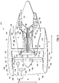
- turbofan engine 110 depicted in FIG. 1 is by way of example only, turbofan engine 110 may have any other suitable configuration. It should also be appreciated, that the present invention may be incorporated into any other suitable gas turbine engine. For example, the present invention may be incorporated into, e.g., a turboprop engine.
- exemplary fan section 114 includes fan case 150 that circumferentially surrounds fan 138 and/or at least a portion of core turbine engine 116. It should be appreciated that fan case 150 may be configured to be supported relative to core turbine engine 116 by a plurality of circumferentially-spaced outlet guide vanes 152. Moreover, a downstream section 154 of fan case 150 may extend over an outer portion of core turbine engine 116 so as to define a bypass airflow passage 156 therebetween.
- Abradable liners 157 are positioned between forward acoustic liners 153 and aft acoustic liners 155 and between tip 141 of fan blades 140 and fan case 150. Acoustic liners 153 and 155 are configured to dampen or reduce noise generated by turbofan engine 110, specifically fan section 114. Fan blades 140 are configured to cut into abradable liners 157 to control tolerances around fan blades 140.
- detection system 200 While detection of entrained water does not necessarily indicate that corrosion and/or other damage to fan case 150 has occurred, the detection of entrained water does indicate where there is an increased likelihood for corrosion and/or other damage to occur. As such, because entrainment of water is typically a precursor to corrosion and/or other damage, detection system 200 decreases the likelihood of corrosion by detecting the entrained water before corrosion and/or other damage has occurred. Additionally, as described below, detection system 200 is configured to detect entrained water without removing liners 153, 155, and 157. As such, detection system 200 reduces inspection labor cost and the downtime of turbofan engine 110 by detecting water without removing liners 153, 155, and 157. Accordingly, detection system 200 provides a portable, cost effective method for detecting entrained water that detects water before corrosion and/or other damage has occurred.
- fan case 150 and detection system 200 may be configured in four detection configurations.
- a first detection configuration shown in FIG. 1
- fan case 150 is in the installed orientation and heat lamp 208 is positioned to heat inner radial surface 151.
- a second detection configuration shown in FIG. 2
- fan case 150 is in the installed orientation and heating blanket 210 is positioned to heat outer radial surface 159.
- a third detection configuration shown in FIG. 3
- fan case 150 is in the uninstalled orientation and heat lamp 208 is positioned to heat inner radial surface 151.
- a fourth detection configuration shown in FIG. 4
- fan case 150 is in the uninstalled orientation and heating blanket 210 is positioned to heat outer radial surface 159.
- Regions of fan case 150 that do not contain entrained water will not absorb heat from heater 202 as efficiently as regions of fan case 150 that contain entrained water, and, as such, less infrared radiation will be emitted from regions of fan case 150 that do not contain entrained water.
- monitoring camera 204 is very sensitive to small, temporal changes in temperature.
- the effect of entrained water on the heating and/or cooling rate can be used to detect the presence of entrained water and the location of the entrained water in fan case 150 and/or liners 153, 155, and 157.
- the local transient thermal gradient detected by monitoring camera 204 is dependent on the position of heater 202. For example, when heat lamp 208 is heating inner radial surface 151, entrained water will absorb more heat than surrounding portions of fan case 150 and/or liners 153, 155, and 157. Accordingly, a first area of fan case 150 and/or liners 153, 155, and 157 that contacts the entrained water will have a first transient temperature, and a second area of fan case 150 and/or liners 153, 155, and 157 that does not contact the entrained water will have a second transient temperature higher than the first transient temperature.
- Computing device 206 includes a computer system that includes at least one processing device (not shown in FIG. 1 ) and at least one memory device (not shown in FIG. 1 ) that executes executable instructions to analyze images from monitoring camera 204.
- Computing device 206 includes, for example, image processing software or other analytic software configured to analyze images and/or video from monitoring camera 204.
- Computing device 206 is also configured to operate at least partially as a data acquisition device and to monitor and/or analyze a condition of fan case 150.
- Computing device 206 receives and processes images from monitoring camera 204.
- Computing device 206 stores and analyzes the images, which are used to facilitate maintaining and repairing fan case 150.
- the different detection configurations shown in FIGS. 1-4 are described below in detail.
- Heat lamp 208 is positioned proximate inner radial surface 151 on upper portion 161 of fan case 150 and activated such that heat lamp 208 directs infrared radiation toward inner radial surface 151 on upper portion 161 of fan case 150. Specifically, heat lamp 208 heats inner radial surface 151 on upper portion 161 of fan case 150 such that local temperature gradients are created where entrained water is present.
- Monitoring camera 204 acquires a plurality of images and/or video of inner radial surface 151 on upper portion 161 of fan case 150 and sends the images and/or video to computing device 206.
- Computing device 206 analyzes the images and/or video to determine and detect the presence of entrained water between fan case 150 and liners 153, 155, and 157. If appropriate, computing device 206 then sends a notification to an operator that entrained water may be present.
- FIG. 3 is a schematic cross-sectional view of fan case 150 and detection system 200 in a third detection configuration.
- FIG. 4 is a schematic cross-sectional view of fan case 150 and detection system 200 in a fourth detection configuration.
- Fan case 150 is illustrated in an uninstalled orientation in FIGS. 3 and 4 .
- fan case 150 does not circumscribe turbofan engine 110 and is oriented such that inlet 160 of fan case 150 faces downward (relative to the direction of gravity). Gravity causes entrained water to physically contact both fan case 150 and liners 153, 155, and 157.
- both heat lamp 208 and heating blanket 210 may be used by detection system 200 to detect entrained water, in accordance with the present invention.
- Monitoring camera 204 acquires a plurality of images and/or video of inner radial surface 151 of fan case 150 and sends the images and/or video to computing device 206.
- Computing device 206 analyzes the images and/or video to determine and detect the presence of entrained water between fan case 150 and liners 153, 155, and 157. If appropriate, computing device 206 then sends a notification to the operator that entrained water may be present.
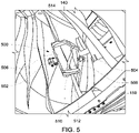
- First and second cushions 506 and 508 are configured to protect fan blade 140 from first and second monitoring cameras 502 and 504.
- First monitoring camera 502 is configured to image liners 153 and 157 forward of fan blades 140
- second monitoring camera 504 is configured to image liners 155 and 157 aft of fan blades 140.
- Fan blades 140 can be rotated to enable monitoring camera system 500 to image an entire inner circumference of inner radial surface 151. Because monitoring camera system 500 is installed on fan blades 140, monitoring camera system 500 can only be used when fan case 150 is in the installed orientation.
- FIG. 6 is an exemplary image 600 acquired by monitoring camera 204 and/or monitoring camera system 500 of fan case 150 and/or liners 153, 155, and 157.
- Image 600 is a gray scale image of fan case 150 and/or liners 153, 155, and 157. Darker regions in image 600 indicate regions with lower temperatures, or cold spots, and lighter regions in image 600 indicate regions with higher temperatures, or hot spots.
- monitoring camera 204 and/or monitoring camera system 500 facilitate differentiating regions of higher temperature from regions of lower temperature by showing dark regions and light regions on image 600.
- computing device 206 can detect dark regions and/or light regions and segments the detected regions into a region of interest (ROI) 602.
- ROI 602 is a rectangular region within image 600 that demarcates a dark region and/or a light region.
- ROI 602 is shown as a rectangular region in image 600, ROI 602 may alternatively have any shape that enables detection system 200 to operate as described herein.
- the shape of ROI 602 can be any shape that allows detection system 200 to detect local temperature gradients on inner radial surface 151 under liners 153, 155, and 157.
- ROI 602 may be a circle.
- the image processing software includes image processing tools, such as segmentation, auto thresholding, local thresholding, and histogram equalization to visualize regions of entrained water, and signal processing tools to extract quantitative information about the amount of entrained water present in fan case 150 and/or liners 153, 155, and 157.
- image processing tools such as segmentation, auto thresholding, local thresholding, and histogram equalization to visualize regions of entrained water
- signal processing tools to extract quantitative information about the amount of entrained water present in fan case 150 and/or liners 153, 155, and 157.
- computing device 206 and/or monitoring camera 204 may include a position tracking device (not shown) configured to track where each image 600 was acquired on inner radial surface 151 of fan case 150.
- Computing device 206 may also use analytic software to develop models that predict the probability of entrained water based on the local transient thermal gradient detected.
- computing device 206 may be configured to determine a volume of water within fan case 150 based on the plurality of images and/or video of inner radial surface 151 of fan case 150. For example, a higher contrast between first area 604 and second area 606 may indicate a greater volume of entrained water.
- monitoring camera 204 may send videos of ROI 602 rather than single images. The videos may show how the local temperature gradient between first area 604 and second area 606 changes over time, and computing device 206 may use analytic software to develop models that predict the volume of entrained water based on the change in the temperature gradient over time.
- fan case 150 and detection system 200 were arranged in the second detection configuration, where fan case 150 was in the installed orientation and heating blanket 210 was positioned to heat outer radial surface 159.
- Monitoring camera system 500 was positioned to acquire images of liners 153, 155, and 157 and fan case 150. Specifically, monitoring camera system 500 was positioned as shown in FIG. 5 to be rotated within fan case 150. Heating blanket 210 heated fan case 150 for 2 minutes and raised the temperature of fan case 150 10 Celsius (°C) above the ambient temperature, and thereby increasing the infrared emission from fan case 150.
- Monitoring camera system 500 was rotated within fan case 150 and acquired image 600 of fan case 150 and/or liners 153, 155, and 157 as shown in FIG. 6 .
- Computing device 206 used analytic software and predicted the probability of entrained water based on the local transient thermal gradient detected within image 600 as described above.
- fan case 150 and detection system 200 were arranged in the first detection configuration, where fan case 150 was in the installed orientation and heater 202 was positioned to heat liners 153, 155, and 157 and fan case 150 on inner radial surface 151 of fan case 150. Specifically, first, heater 202 heated a portion of liners 153, 155, and 157 and fan case 150. Heater 202 heated fan case 150 for approximately 5 to 10 seconds and raised the temperature of fan case 150 10 °C above the ambient temperature, and thereby increasing the infrared emission from fan case 150.
- monitoring camera system 500 was positioned to acquire images of the heated portion of liners 153, 155, and 157 and fan case 150. Specifically, monitoring camera system 500 was positioned as shown in FIG. 5 to be rotated within fan case 150, and monitoring camera system 500 was rotated to acquire images of the heated portion of liners 153, 155, and 157 and fan case 150. Monitoring camera system 500 acquired image 600 of fan case 150 and/or liners 153, 155, and 157 as shown in FIG. 6 . Computing device 206 used analytic software and predicted the probability of entrained water based on the local transient thermal gradient detected within image 600 as described above.
- the monitoring camera is an infrared camera configured to image the liners and/or the fan case.
- the monitoring camera acquires a plurality of images of an inner radial surface of the fan case, and the local temperature gradients appear as light or dark spots on the images.
- the images are sent to the computing device where image processing software analyzes the images to determine if water is entrained behind the liners.
- the computing device then alerts the operator to the potential presence of entrained water.
- the detection system reduces inspection costs by detecting entrained water without removing the liners from the fan case and/or the fan case from the engine. As such, the labor cost of inspecting the fan case is reduced by using the detection system to detect water rather than removing the liners from the fan case. Additionally, the detection system also reduces operating costs of the gas turbine engine by reducing downtime because the fan case and the liners are not removed from the engine.
- An exemplary technical effect of the methods and systems described herein includes: (a) imaging a fan case; (b) analyzing the images of the fan case to detect a local transient thermal gradient on the fan case; and (c) alerting an operator of potential entrained water within the fan case based on the detected local transient thermal gradient.
- the invention uses a computing device.
- Such devices typically include a processor, processing device, or controller, such as a general purpose central processing unit (CPU), a graphics processing unit (GPU), a microcontroller, a reduced instruction set computer (RISC) processor, an application specific integrated circuit (ASIC), a programmable logic circuit (PLC), a field programmable gate array (FPGA), a digital signal processing (DSP) device, and/or any other circuit or processing device capable of executing the functions described herein.
- the methods described herein may be encoded as executable instructions embodied in a computer readable medium, including, without limitation, a storage device and/or a memory device. Such instructions, when executed by a processing device, cause the processing device to perform at least a portion of the methods described herein.
- the above examples are exemplary only, and thus are not intended to limit in any way the definition and/or meaning of the term processor and processing device.
Landscapes
- Engineering & Computer Science (AREA)
- Physics & Mathematics (AREA)
- General Physics & Mathematics (AREA)
- Life Sciences & Earth Sciences (AREA)
- Theoretical Computer Science (AREA)
- Chemical & Material Sciences (AREA)
- Biochemistry (AREA)
- Pathology (AREA)
- Immunology (AREA)
- Health & Medical Sciences (AREA)
- General Health & Medical Sciences (AREA)
- Analytical Chemistry (AREA)
- Quality & Reliability (AREA)
- Computer Vision & Pattern Recognition (AREA)
- Mechanical Engineering (AREA)
- General Engineering & Computer Science (AREA)
- Geophysics (AREA)
- General Life Sciences & Earth Sciences (AREA)
- Multimedia (AREA)
- Radar, Positioning & Navigation (AREA)
- Remote Sensing (AREA)
- Investigating Or Analyzing Materials Using Thermal Means (AREA)
Claims (4)
- Système de détection (200) conçu pour détecter de l'eau dans un carter de soufflante (150), ledit système de détection (200) comprenant :un dispositif de chauffage (202) conçu pour appliquer de la chaleur au carter de soufflante (150), dans lequel toute eau à l'intérieur du carter de soufflante (150) génère un gradient thermique transitoire local en réponse à la chaleur appliquée ;une caméra de surveillance (204) conçue pour être positionnée à proximité du carter de soufflante (150) et configurée pour acquérir une pluralité d'images (600) du carter de soufflante chauffé (150) ; etun dispositif informatique (206) configuré pour :recevoir la pluralité d'images (600) à partir de ladite caméra de surveillance (204) ; etanalyser la pluralité d'images (600) pour détecter l'eau dans le carter de soufflante (150) ; le système de détection (200) étant caractérisé en ce que :
ledit dispositif de chauffage (202) comprend une lampe de chauffage (208) conçue pour chauffer une surface radiale interne (151) dudit carter de soufflante (150) et comprend en outre une couverture chauffante (210) conçue pour chauffer une surface radiale externe (159) dudit carter de soufflante (150). - Système de détection (200) selon la revendication 1, dans lequel ladite caméra de surveillance (204) comprend une caméra infrarouge (204).
- Système de détection (200) selon la revendication 1 ou 2, dans lequel ladite couverture chauffante (210) est conçue pour être appliquée à ladite surface radiale externe (159) dudit carter de soufflante (150).
- Système de détection (200) selon l'une quelconque des revendications 1 à 3, dans lequel ladite caméra de surveillance (204) est conçue pour être positionnée pour acquérir une pluralité d'images (600) d'une surface radiale interne (151) dudit carter de soufflante (150).
Applications Claiming Priority (1)
| Application Number | Priority Date | Filing Date | Title |
|---|---|---|---|
| US16/244,962 US11474058B2 (en) | 2019-01-10 | 2019-01-10 | Systems and methods for detecting water in a fan case |
Publications (3)
| Publication Number | Publication Date |
|---|---|
| EP3680651A2 EP3680651A2 (fr) | 2020-07-15 |
| EP3680651A3 EP3680651A3 (fr) | 2020-08-12 |
| EP3680651B1 true EP3680651B1 (fr) | 2022-12-28 |
Family
ID=69157594
Family Applications (1)
| Application Number | Title | Priority Date | Filing Date |
|---|---|---|---|
| EP20150555.9A Active EP3680651B1 (fr) | 2019-01-10 | 2020-01-07 | Système thermographique de détection de l'eau dans un boîtier de ventilateur |
Country Status (3)
| Country | Link |
|---|---|
| US (1) | US11474058B2 (fr) |
| EP (1) | EP3680651B1 (fr) |
| CN (1) | CN111505728B (fr) |
Families Citing this family (2)
| Publication number | Priority date | Publication date | Assignee | Title |
|---|---|---|---|---|
| EP3988929A1 (fr) * | 2020-10-20 | 2022-04-27 | Wobben Properties GmbH | Procédé de vérification d'un assemblage soudé d'un stator de générateur d'une éolienne ainsi que support destiné à la mise en uvre du procédé et système pourvu de support |
| US12359672B2 (en) * | 2023-04-18 | 2025-07-15 | Rtx Corporation | Rotor blade inspection system |
Family Cites Families (20)
| Publication number | Priority date | Publication date | Assignee | Title |
|---|---|---|---|---|
| US4647220A (en) | 1984-07-09 | 1987-03-03 | Lockheed Corporation | Method of and apparatus for detecting corrosion utilizing infrared analysis |
| JP2967227B2 (ja) * | 1987-09-21 | 1999-10-25 | 千晴 吉原 | 復合材料の製造法およびプレス型 |
| JPH06117247A (ja) * | 1992-09-30 | 1994-04-26 | Mazda Motor Corp | エンジンの制御装置 |
| JPH07229867A (ja) * | 1993-08-31 | 1995-08-29 | Matsushita Electric Ind Co Ltd | 水分検知センサー、水分検知方法及び水分検知センサーを用いた乾燥機 |
| CA2496935C (fr) | 2002-08-28 | 2011-09-13 | Wayne State University | Systeme et procede pour la production d'un chaos acoustique en imagerie infrarouge sonique |
| US20060114965A1 (en) | 2003-10-10 | 2006-06-01 | Murphy John C | Thermal-based methods for nondestructive evaluation |
| US20080111074A1 (en) | 2004-10-22 | 2008-05-15 | Northrop Grumman Corporation | Method for infrared imaging of substrates through coatings |
| FR2893135B1 (fr) | 2005-11-10 | 2008-08-29 | Airbus France Sa | Systeme de detection et de localisation d'eau dans une structure sandwich d'aeronef |
| US7605924B2 (en) * | 2006-12-06 | 2009-10-20 | Lockheed Martin Corporation | Laser-ultrasound inspection using infrared thermography |
| ES2336166B1 (es) | 2007-04-11 | 2011-02-10 | Fundacion Centro De Tecnologias Aeronauticas | Metodo de inspeccion de defectos producidos en material compuesto de fibra de carbono por pinchazo en bolsa durante el proceso de fabricacion. |
| US9004753B1 (en) | 2010-10-01 | 2015-04-14 | Kurion, Inc. | Infrared detection of defects in wind turbine blades |
| US9488592B1 (en) | 2011-09-28 | 2016-11-08 | Kurion, Inc. | Automatic detection of defects in composite structures using NDT methods |
| JP5827926B2 (ja) | 2012-06-19 | 2015-12-02 | 日本電信電話株式会社 | 湿度推定装置を用いたレコメンドサービスシステム、方法およびプログラム |
| US9255526B2 (en) * | 2012-08-23 | 2016-02-09 | Siemens Energy, Inc. | System and method for on line monitoring within a gas turbine combustor section |
| US9518946B2 (en) * | 2013-12-04 | 2016-12-13 | Watlow Electric Manufacturing Company | Thermographic inspection system |
| CN104373191B (zh) * | 2014-11-14 | 2017-02-22 | 丹东华隆农业机械有限公司 | 一种农用发动机水箱自动除尘装置 |
| US10670531B2 (en) | 2016-01-04 | 2020-06-02 | Laser & Plasma Technologies, LLC | Infrared detection camera |
| US10473528B2 (en) | 2016-02-13 | 2019-11-12 | General Electric Company | Optical apparatus and sight tube for inspecting turbine engine components |
| CN108663366A (zh) * | 2018-03-29 | 2018-10-16 | 北京理工大学 | 一种固体火箭发动机内部涂层涂覆质量检测装置 |
| CN108811448A (zh) * | 2018-06-27 | 2018-11-13 | 郑州格瑞塔电子信息技术有限公司 | 一种通信设备用防潮防盗的户外机柜箱 |
-
2019
- 2019-01-10 US US16/244,962 patent/US11474058B2/en active Active
-
2020
- 2020-01-07 EP EP20150555.9A patent/EP3680651B1/fr active Active
- 2020-01-10 CN CN202010027128.2A patent/CN111505728B/zh active Active
Also Published As
| Publication number | Publication date |
|---|---|
| US20200225178A1 (en) | 2020-07-16 |
| CN111505728A (zh) | 2020-08-07 |
| EP3680651A2 (fr) | 2020-07-15 |
| EP3680651A3 (fr) | 2020-08-12 |
| US11474058B2 (en) | 2022-10-18 |
| CN111505728B (zh) | 2023-10-31 |
Similar Documents
| Publication | Publication Date | Title |
|---|---|---|
| US9976967B2 (en) | System for detecting defects on an object | |
| US10685433B2 (en) | Nondestructive coating imperfection detection system and method therefor | |
| EP2354783B1 (fr) | Système d'inspection thermique et procédé incorporant un écoulement externe | |
| EP3680651B1 (fr) | Système thermographique de détection de l'eau dans un boîtier de ventilateur | |
| US20200016702A1 (en) | Systems and methods for thermal location of cooling holes | |
| US20090297336A1 (en) | Online systems and methods for thermal inspection of parts | |
| KR102195273B1 (ko) | 터빈 구성요소들을 검사하기 위한 플래시 서모그래피 디바이스 | |
| US12146416B2 (en) | Propulsor blade imaging assembly for an aircraft propulsion system | |
| US11340184B2 (en) | Engine component performance inspection sleeve and method of inspecting engine component | |
| US10142565B2 (en) | Flash thermography borescope | |
| Pan et al. | A crack detection method for aero-engine blade based on air-flow thermography | |
| US11976997B2 (en) | Inspection method for inspecting a condition of an externally invisible component of a device using a borescope | |
| EP2899539B1 (fr) | Procédé de contrôle de la doublure de piste de ventilateur d'un moteur à turbine à gaz | |
| US20240352869A1 (en) | Propulsor blade imaging assembly for an aircraft propulsion system | |
| DeShong et al. | Applying Infrared Thermography as a Method for Online Monitoring of Turbine Blade Coolant Flow | |
| KR102256543B1 (ko) | 플래시 서모그래피 보어스코프 | |
| US20250383308A1 (en) | Inspection system for detecting surface cracks via eddy current thermography | |
| US20250243816A1 (en) | Turbine engine having an engine core and a bleed air conduit | |
| US20250341425A1 (en) | Automated engine blade inspection methods and system | |
| US20250383307A1 (en) | X-ray diffraction inspection system and method for operating same | |
| US20260065451A1 (en) | System and method for evaluating components using thermography | |
| DEUTSCH et al. | TURBINE DISKS | |
| FR3156183A1 (fr) | Assemblage comportant une enveloppe de fluide entourée d’un tronçon tubulaire délimitant un espace intérieur et un ensemble de capteurs de flux thermique disposé dans l’espace intérieur | |
| JP2003322001A (ja) | ガスタービン翼の冷却穴の目詰まり検知装置及び検知方法 | |
| JP2000328963A (ja) | ガスタービン設備 |
Legal Events
| Date | Code | Title | Description |
|---|---|---|---|
| PUAI | Public reference made under article 153(3) epc to a published international application that has entered the european phase |
Free format text: ORIGINAL CODE: 0009012 |
|
| STAA | Information on the status of an ep patent application or granted ep patent |
Free format text: STATUS: THE APPLICATION HAS BEEN PUBLISHED |
|
| PUAL | Search report despatched |
Free format text: ORIGINAL CODE: 0009013 |
|
| AK | Designated contracting states |
Kind code of ref document: A2 Designated state(s): AL AT BE BG CH CY CZ DE DK EE ES FI FR GB GR HR HU IE IS IT LI LT LU LV MC MK MT NL NO PL PT RO RS SE SI SK SM TR |
|
| AX | Request for extension of the european patent |
Extension state: BA ME |
|
| AK | Designated contracting states |
Kind code of ref document: A3 Designated state(s): AL AT BE BG CH CY CZ DE DK EE ES FI FR GB GR HR HU IE IS IT LI LT LU LV MC MK MT NL NO PL PT RO RS SE SI SK SM TR |
|
| AX | Request for extension of the european patent |
Extension state: BA ME |
|
| RIC1 | Information provided on ipc code assigned before grant |
Ipc: G01N 25/72 20060101AFI20200704BHEP |
|
| STAA | Information on the status of an ep patent application or granted ep patent |
Free format text: STATUS: REQUEST FOR EXAMINATION WAS MADE |
|
| STAA | Information on the status of an ep patent application or granted ep patent |
Free format text: STATUS: EXAMINATION IS IN PROGRESS |
|
| 17P | Request for examination filed |
Effective date: 20210209 |
|
| RBV | Designated contracting states (corrected) |
Designated state(s): AL AT BE BG CH CY CZ DE DK EE ES FI FR GB GR HR HU IE IS IT LI LT LU LV MC MK MT NL NO PL PT RO RS SE SI SK SM TR |
|
| 17Q | First examination report despatched |
Effective date: 20210304 |
|
| GRAP | Despatch of communication of intention to grant a patent |
Free format text: ORIGINAL CODE: EPIDOSNIGR1 |
|
| STAA | Information on the status of an ep patent application or granted ep patent |
Free format text: STATUS: GRANT OF PATENT IS INTENDED |
|
| INTG | Intention to grant announced |
Effective date: 20220722 |
|
| GRAS | Grant fee paid |
Free format text: ORIGINAL CODE: EPIDOSNIGR3 |
|
| GRAA | (expected) grant |
Free format text: ORIGINAL CODE: 0009210 |
|
| STAA | Information on the status of an ep patent application or granted ep patent |
Free format text: STATUS: THE PATENT HAS BEEN GRANTED |
|
| AK | Designated contracting states |
Kind code of ref document: B1 Designated state(s): AL AT BE BG CH CY CZ DE DK EE ES FI FR GB GR HR HU IE IS IT LI LT LU LV MC MK MT NL NO PL PT RO RS SE SI SK SM TR |
|
| REG | Reference to a national code |
Ref country code: GB Ref legal event code: FG4D |
|
| REG | Reference to a national code |
Ref country code: CH Ref legal event code: EP |
|
| REG | Reference to a national code |
Ref country code: DE Ref legal event code: R096 Ref document number: 602020007123 Country of ref document: DE |
|
| REG | Reference to a national code |
Ref country code: AT Ref legal event code: REF Ref document number: 1540799 Country of ref document: AT Kind code of ref document: T Effective date: 20230115 |
|
| REG | Reference to a national code |
Ref country code: IE Ref legal event code: FG4D |
|
| REG | Reference to a national code |
Ref country code: LT Ref legal event code: MG9D |
|
| PG25 | Lapsed in a contracting state [announced via postgrant information from national office to epo] |
Ref country code: SE Free format text: LAPSE BECAUSE OF FAILURE TO SUBMIT A TRANSLATION OF THE DESCRIPTION OR TO PAY THE FEE WITHIN THE PRESCRIBED TIME-LIMIT Effective date: 20221228 Ref country code: NO Free format text: LAPSE BECAUSE OF FAILURE TO SUBMIT A TRANSLATION OF THE DESCRIPTION OR TO PAY THE FEE WITHIN THE PRESCRIBED TIME-LIMIT Effective date: 20230328 Ref country code: LT Free format text: LAPSE BECAUSE OF FAILURE TO SUBMIT A TRANSLATION OF THE DESCRIPTION OR TO PAY THE FEE WITHIN THE PRESCRIBED TIME-LIMIT Effective date: 20221228 Ref country code: FI Free format text: LAPSE BECAUSE OF FAILURE TO SUBMIT A TRANSLATION OF THE DESCRIPTION OR TO PAY THE FEE WITHIN THE PRESCRIBED TIME-LIMIT Effective date: 20221228 |
|
| REG | Reference to a national code |
Ref country code: NL Ref legal event code: MP Effective date: 20221228 |
|
| REG | Reference to a national code |
Ref country code: AT Ref legal event code: MK05 Ref document number: 1540799 Country of ref document: AT Kind code of ref document: T Effective date: 20221228 |
|
| PG25 | Lapsed in a contracting state [announced via postgrant information from national office to epo] |
Ref country code: RS Free format text: LAPSE BECAUSE OF FAILURE TO SUBMIT A TRANSLATION OF THE DESCRIPTION OR TO PAY THE FEE WITHIN THE PRESCRIBED TIME-LIMIT Effective date: 20221228 Ref country code: LV Free format text: LAPSE BECAUSE OF FAILURE TO SUBMIT A TRANSLATION OF THE DESCRIPTION OR TO PAY THE FEE WITHIN THE PRESCRIBED TIME-LIMIT Effective date: 20221228 Ref country code: HR Free format text: LAPSE BECAUSE OF FAILURE TO SUBMIT A TRANSLATION OF THE DESCRIPTION OR TO PAY THE FEE WITHIN THE PRESCRIBED TIME-LIMIT Effective date: 20221228 Ref country code: GR Free format text: LAPSE BECAUSE OF FAILURE TO SUBMIT A TRANSLATION OF THE DESCRIPTION OR TO PAY THE FEE WITHIN THE PRESCRIBED TIME-LIMIT Effective date: 20230329 |
|
| P01 | Opt-out of the competence of the unified patent court (upc) registered |
Effective date: 20230411 |
|
| PG25 | Lapsed in a contracting state [announced via postgrant information from national office to epo] |
Ref country code: NL Free format text: LAPSE BECAUSE OF FAILURE TO SUBMIT A TRANSLATION OF THE DESCRIPTION OR TO PAY THE FEE WITHIN THE PRESCRIBED TIME-LIMIT Effective date: 20221228 |
|
| PG25 | Lapsed in a contracting state [announced via postgrant information from national office to epo] |
Ref country code: SM Free format text: LAPSE BECAUSE OF FAILURE TO SUBMIT A TRANSLATION OF THE DESCRIPTION OR TO PAY THE FEE WITHIN THE PRESCRIBED TIME-LIMIT Effective date: 20221228 Ref country code: RO Free format text: LAPSE BECAUSE OF FAILURE TO SUBMIT A TRANSLATION OF THE DESCRIPTION OR TO PAY THE FEE WITHIN THE PRESCRIBED TIME-LIMIT Effective date: 20221228 Ref country code: PT Free format text: LAPSE BECAUSE OF FAILURE TO SUBMIT A TRANSLATION OF THE DESCRIPTION OR TO PAY THE FEE WITHIN THE PRESCRIBED TIME-LIMIT Effective date: 20230428 Ref country code: ES Free format text: LAPSE BECAUSE OF FAILURE TO SUBMIT A TRANSLATION OF THE DESCRIPTION OR TO PAY THE FEE WITHIN THE PRESCRIBED TIME-LIMIT Effective date: 20221228 Ref country code: EE Free format text: LAPSE BECAUSE OF FAILURE TO SUBMIT A TRANSLATION OF THE DESCRIPTION OR TO PAY THE FEE WITHIN THE PRESCRIBED TIME-LIMIT Effective date: 20221228 Ref country code: CZ Free format text: LAPSE BECAUSE OF FAILURE TO SUBMIT A TRANSLATION OF THE DESCRIPTION OR TO PAY THE FEE WITHIN THE PRESCRIBED TIME-LIMIT Effective date: 20221228 Ref country code: AT Free format text: LAPSE BECAUSE OF FAILURE TO SUBMIT A TRANSLATION OF THE DESCRIPTION OR TO PAY THE FEE WITHIN THE PRESCRIBED TIME-LIMIT Effective date: 20221228 |
|
| PG25 | Lapsed in a contracting state [announced via postgrant information from national office to epo] |
Ref country code: SK Free format text: LAPSE BECAUSE OF FAILURE TO SUBMIT A TRANSLATION OF THE DESCRIPTION OR TO PAY THE FEE WITHIN THE PRESCRIBED TIME-LIMIT Effective date: 20221228 Ref country code: PL Free format text: LAPSE BECAUSE OF FAILURE TO SUBMIT A TRANSLATION OF THE DESCRIPTION OR TO PAY THE FEE WITHIN THE PRESCRIBED TIME-LIMIT Effective date: 20221228 Ref country code: IS Free format text: LAPSE BECAUSE OF FAILURE TO SUBMIT A TRANSLATION OF THE DESCRIPTION OR TO PAY THE FEE WITHIN THE PRESCRIBED TIME-LIMIT Effective date: 20230428 Ref country code: AL Free format text: LAPSE BECAUSE OF FAILURE TO SUBMIT A TRANSLATION OF THE DESCRIPTION OR TO PAY THE FEE WITHIN THE PRESCRIBED TIME-LIMIT Effective date: 20221228 |
|
| REG | Reference to a national code |
Ref country code: CH Ref legal event code: PL |
|
| PG25 | Lapsed in a contracting state [announced via postgrant information from national office to epo] |
Ref country code: MC Free format text: LAPSE BECAUSE OF FAILURE TO SUBMIT A TRANSLATION OF THE DESCRIPTION OR TO PAY THE FEE WITHIN THE PRESCRIBED TIME-LIMIT Effective date: 20221228 Ref country code: LU Free format text: LAPSE BECAUSE OF NON-PAYMENT OF DUE FEES Effective date: 20230107 |
|
| REG | Reference to a national code |
Ref country code: DE Ref legal event code: R097 Ref document number: 602020007123 Country of ref document: DE |
|
| REG | Reference to a national code |
Ref country code: BE Ref legal event code: MM Effective date: 20230131 |
|
| PG25 | Lapsed in a contracting state [announced via postgrant information from national office to epo] |
Ref country code: LI Free format text: LAPSE BECAUSE OF NON-PAYMENT OF DUE FEES Effective date: 20230131 Ref country code: DK Free format text: LAPSE BECAUSE OF FAILURE TO SUBMIT A TRANSLATION OF THE DESCRIPTION OR TO PAY THE FEE WITHIN THE PRESCRIBED TIME-LIMIT Effective date: 20221228 Ref country code: CH Free format text: LAPSE BECAUSE OF NON-PAYMENT OF DUE FEES Effective date: 20230131 |
|
| PLBE | No opposition filed within time limit |
Free format text: ORIGINAL CODE: 0009261 |
|
| STAA | Information on the status of an ep patent application or granted ep patent |
Free format text: STATUS: NO OPPOSITION FILED WITHIN TIME LIMIT |
|
| PG25 | Lapsed in a contracting state [announced via postgrant information from national office to epo] |
Ref country code: BE Free format text: LAPSE BECAUSE OF NON-PAYMENT OF DUE FEES Effective date: 20230131 |
|
| 26N | No opposition filed |
Effective date: 20230929 |
|
| PG25 | Lapsed in a contracting state [announced via postgrant information from national office to epo] |
Ref country code: SI Free format text: LAPSE BECAUSE OF FAILURE TO SUBMIT A TRANSLATION OF THE DESCRIPTION OR TO PAY THE FEE WITHIN THE PRESCRIBED TIME-LIMIT Effective date: 20221228 Ref country code: IE Free format text: LAPSE BECAUSE OF NON-PAYMENT OF DUE FEES Effective date: 20230107 |
|
| PG25 | Lapsed in a contracting state [announced via postgrant information from national office to epo] |
Ref country code: IT Free format text: LAPSE BECAUSE OF FAILURE TO SUBMIT A TRANSLATION OF THE DESCRIPTION OR TO PAY THE FEE WITHIN THE PRESCRIBED TIME-LIMIT Effective date: 20221228 |
|
| PG25 | Lapsed in a contracting state [announced via postgrant information from national office to epo] |
Ref country code: BG Free format text: LAPSE BECAUSE OF FAILURE TO SUBMIT A TRANSLATION OF THE DESCRIPTION OR TO PAY THE FEE WITHIN THE PRESCRIBED TIME-LIMIT Effective date: 20221228 |
|
| PG25 | Lapsed in a contracting state [announced via postgrant information from national office to epo] |
Ref country code: BG Free format text: LAPSE BECAUSE OF FAILURE TO SUBMIT A TRANSLATION OF THE DESCRIPTION OR TO PAY THE FEE WITHIN THE PRESCRIBED TIME-LIMIT Effective date: 20221228 |
|
| PG25 | Lapsed in a contracting state [announced via postgrant information from national office to epo] |
Ref country code: CY Free format text: LAPSE BECAUSE OF FAILURE TO SUBMIT A TRANSLATION OF THE DESCRIPTION OR TO PAY THE FEE WITHIN THE PRESCRIBED TIME-LIMIT; INVALID AB INITIO Effective date: 20200107 |
|
| PG25 | Lapsed in a contracting state [announced via postgrant information from national office to epo] |
Ref country code: HU Free format text: LAPSE BECAUSE OF FAILURE TO SUBMIT A TRANSLATION OF THE DESCRIPTION OR TO PAY THE FEE WITHIN THE PRESCRIBED TIME-LIMIT; INVALID AB INITIO Effective date: 20200107 |
|
| PG25 | Lapsed in a contracting state [announced via postgrant information from national office to epo] |
Ref country code: TR Free format text: LAPSE BECAUSE OF FAILURE TO SUBMIT A TRANSLATION OF THE DESCRIPTION OR TO PAY THE FEE WITHIN THE PRESCRIBED TIME-LIMIT Effective date: 20221228 |
|
| PGFP | Annual fee paid to national office [announced via postgrant information from national office to epo] |
Ref country code: GB Payment date: 20251219 Year of fee payment: 7 |
|
| PGFP | Annual fee paid to national office [announced via postgrant information from national office to epo] |
Ref country code: FR Payment date: 20251217 Year of fee payment: 7 |
|
| PGFP | Annual fee paid to national office [announced via postgrant information from national office to epo] |
Ref country code: DE Payment date: 20251217 Year of fee payment: 7 |