EP3680663A1 - Substrat für biochip, biochip, verfahren zur herstellung eines biochips und verfahren zur konservierung eines biochips - Google Patents
Substrat für biochip, biochip, verfahren zur herstellung eines biochips und verfahren zur konservierung eines biochips Download PDFInfo
- Publication number
- EP3680663A1 EP3680663A1 EP18853298.0A EP18853298A EP3680663A1 EP 3680663 A1 EP3680663 A1 EP 3680663A1 EP 18853298 A EP18853298 A EP 18853298A EP 3680663 A1 EP3680663 A1 EP 3680663A1
- Authority
- EP
- European Patent Office
- Prior art keywords
- biochip
- immobilized
- substrate
- reaction area
- solution
- Prior art date
- Legal status (The legal status is an assumption and is not a legal conclusion. Google has not performed a legal analysis and makes no representation as to the accuracy of the status listed.)
- Granted
Links
Images







Classifications
-
- B—PERFORMING OPERATIONS; TRANSPORTING
- B01—PHYSICAL OR CHEMICAL PROCESSES OR APPARATUS IN GENERAL
- B01J—CHEMICAL OR PHYSICAL PROCESSES, e.g. CATALYSIS OR COLLOID CHEMISTRY; THEIR RELEVANT APPARATUS
- B01J19/00—Chemical, physical or physico-chemical processes in general; Their relevant apparatus
- B01J19/0046—Sequential or parallel reactions, e.g. for the synthesis of polypeptides or polynucleotides; Apparatus and devices for combinatorial chemistry or for making molecular arrays
-
- G—PHYSICS
- G01—MEASURING; TESTING
- G01N—INVESTIGATING OR ANALYSING MATERIALS BY DETERMINING THEIR CHEMICAL OR PHYSICAL PROPERTIES
- G01N33/00—Investigating or analysing materials by specific methods not covered by groups G01N1/00 - G01N31/00
- G01N33/48—Biological material, e.g. blood, urine; Haemocytometers
- G01N33/50—Chemical analysis of biological material, e.g. blood, urine; Testing involving biospecific ligand binding methods; Immunological testing
- G01N33/53—Immunoassay; Biospecific binding assay; Materials therefor
- G01N33/543—Immunoassay; Biospecific binding assay; Materials therefor with an insoluble carrier for immobilising immunochemicals
- G01N33/54393—Improving reaction conditions or stability, e.g. by coating or irradiation of surface, by reduction of non-specific binding, by promotion of specific binding
-
- G—PHYSICS
- G01—MEASURING; TESTING
- G01N—INVESTIGATING OR ANALYSING MATERIALS BY DETERMINING THEIR CHEMICAL OR PHYSICAL PROPERTIES
- G01N33/00—Investigating or analysing materials by specific methods not covered by groups G01N1/00 - G01N31/00
- G01N33/48—Biological material, e.g. blood, urine; Haemocytometers
- G01N33/50—Chemical analysis of biological material, e.g. blood, urine; Testing involving biospecific ligand binding methods; Immunological testing
- G01N33/53—Immunoassay; Biospecific binding assay; Materials therefor
- G01N33/543—Immunoassay; Biospecific binding assay; Materials therefor with an insoluble carrier for immobilising immunochemicals
- G01N33/544—Immunoassay; Biospecific binding assay; Materials therefor with an insoluble carrier for immobilising immunochemicals the carrier being organic
- G01N33/545—Synthetic resin
-
- G—PHYSICS
- G01—MEASURING; TESTING
- G01N—INVESTIGATING OR ANALYSING MATERIALS BY DETERMINING THEIR CHEMICAL OR PHYSICAL PROPERTIES
- G01N37/00—Details not covered by any other group of this subclass
-
- B—PERFORMING OPERATIONS; TRANSPORTING
- B01—PHYSICAL OR CHEMICAL PROCESSES OR APPARATUS IN GENERAL
- B01J—CHEMICAL OR PHYSICAL PROCESSES, e.g. CATALYSIS OR COLLOID CHEMISTRY; THEIR RELEVANT APPARATUS
- B01J2219/00—Chemical, physical or physico-chemical processes in general; Their relevant apparatus
- B01J2219/00274—Sequential or parallel reactions; Apparatus and devices for combinatorial chemistry or for making arrays; Chemical library technology
- B01J2219/00277—Apparatus
- B01J2219/00497—Features relating to the solid phase supports
- B01J2219/00527—Sheets
- B01J2219/00529—DNA chips
-
- B—PERFORMING OPERATIONS; TRANSPORTING
- B01—PHYSICAL OR CHEMICAL PROCESSES OR APPARATUS IN GENERAL
- B01J—CHEMICAL OR PHYSICAL PROCESSES, e.g. CATALYSIS OR COLLOID CHEMISTRY; THEIR RELEVANT APPARATUS
- B01J2219/00—Chemical, physical or physico-chemical processes in general; Their relevant apparatus
- B01J2219/00274—Sequential or parallel reactions; Apparatus and devices for combinatorial chemistry or for making arrays; Chemical library technology
- B01J2219/00277—Apparatus
- B01J2219/00497—Features relating to the solid phase supports
- B01J2219/00527—Sheets
- B01J2219/00536—Sheets in the shape of disks
-
- B—PERFORMING OPERATIONS; TRANSPORTING
- B01—PHYSICAL OR CHEMICAL PROCESSES OR APPARATUS IN GENERAL
- B01J—CHEMICAL OR PHYSICAL PROCESSES, e.g. CATALYSIS OR COLLOID CHEMISTRY; THEIR RELEVANT APPARATUS
- B01J2219/00—Chemical, physical or physico-chemical processes in general; Their relevant apparatus
- B01J2219/00274—Sequential or parallel reactions; Apparatus and devices for combinatorial chemistry or for making arrays; Chemical library technology
- B01J2219/00583—Features relative to the processes being carried out
- B01J2219/00603—Making arrays on substantially continuous surfaces
- B01J2219/00605—Making arrays on substantially continuous surfaces the compounds being directly bound or immobilised to solid supports
- B01J2219/00608—DNA chips
-
- B—PERFORMING OPERATIONS; TRANSPORTING
- B01—PHYSICAL OR CHEMICAL PROCESSES OR APPARATUS IN GENERAL
- B01J—CHEMICAL OR PHYSICAL PROCESSES, e.g. CATALYSIS OR COLLOID CHEMISTRY; THEIR RELEVANT APPARATUS
- B01J2219/00—Chemical, physical or physico-chemical processes in general; Their relevant apparatus
- B01J2219/00274—Sequential or parallel reactions; Apparatus and devices for combinatorial chemistry or for making arrays; Chemical library technology
- B01J2219/00583—Features relative to the processes being carried out
- B01J2219/00603—Making arrays on substantially continuous surfaces
- B01J2219/00605—Making arrays on substantially continuous surfaces the compounds being directly bound or immobilised to solid supports
- B01J2219/0061—The surface being organic
Definitions
- the present invention relates to a biochip used in the detection or analysis of a biochemical reaction, etc., utilizing a biological material or the like immobilized on a substrate, a substrate used for the biochip, a method for producing the biochip, and a method for preserving the biochip.
- the present invention particularly relates to a chip for inspection and diagnosis, which utilizes an antigen-antibody reaction and is used in allergy tests, tumor marker tests, and the like.
- an immunoplate for immunoassay in which an antibody or an antigen is immobilized on a plate
- a DNA chip in which a nucleic acid is immobilized on a chip and the like have been broadly used.
- biological materials such as proteins or nucleic acids that are used as materials to be immobilized are immobilized, in the form of spots, on the surface of a substrate as a microarray.
- Patent Literature 1 a method comprising spotting BSA on a polymer layer obtained by applying a vinyl polymer of polyethylene glycol monomethacrylate having a polyethylene glycol moiety with a molecular weight of 350 onto an acrylic resin substrate, and then immobilizing the BSA on the substrate according to a photocrosslinking reaction using sodium 4,4'-diazidostilbene-2,2'-disulfonate (Patent Literature 1), and a method comprising spotting N-[4-[3-(trifluoromethyl)-3H-diazirin-3-yl]phenyl]oxirane and peptides on a film obtained by applying a vinyl polymer of polyethylene glycol monomethacrylate having a polyethylene glycol moiety with a molecular weight of 350 onto an acrylic resin substrate, and then immobilizing the peptides thereon (Patent Literature 2) have been disclosed.
- a method of performing the detection or analysis of a biochemical reaction a method comprising introducing maleimide groups in the form of spots into PEG3-OH alkanethiol bound to a chromium- and gold-evaporated glass slide by using 8-AOT and SSMCC, then aligning and immobilizing peptides in the form of spots via the maleimide groups, and then using the thus formed array to supply a test sample to an SPR device, so as to detect phosphorylation of cSrc kinase, has been disclosed (Patent Literature 3).
- Patent Literature 4 discloses a method comprising performing an activation treatment on a silicon- or stainless steel-made microchip coated with diamond/diamond-like carbon, then spotting allergen thereon, inactivating unreacted groups remaining on the chip, further blocking with BSA, and then allowing the chip to react with a test sample.
- a chip capable of detecting a small amount of test sample a chip comprising, on a base material, a plurality of reaction chambers (wells), flow channels connecting with each of the above-described wells, and injection ports for injecting a solution into the above-described flow channels, wheren the chip is capable of analyzing a plurality of test samples or performng a reaction with a small amount of test sample, is disclosed (Patent Literature 5).
- a chip comprising a spot on which a component reacting with a detection target component is immobilized, wherein the spot is disposed in a storage portion capable of storing a liquid test sample, a drainage port for discharging a test sample and a washing solution by centrifugal force, and a separation port, is disclosed (Patent Literature 6).
- the material to be immobilized After a material to be immobilized has been immobilized on a substrate, the material to be immobilized is allowed to react with another physiologically active substance (a material to be detected; a protein, an antigen, etc.) on the surface of the substrate, and a labeled protein is allowed to further react with the reaction mixture, and finally, detection is carried out using a detector or the like.
- a material to be detected other than a capture molecule is immobilized on a portion, on which the capture molecule has not been immobilized, it makes noise upon detection, and causes a decrease in the signal to noise ratio (S/N ratio), thereby reducing detection accuracy.
- S/N ratio signal to noise ratio
- non-specific adsorption of contaminant proteins is often found in serum or plasma used in clinical diagnosis and the like, and thus, high noise is made, and the S/N ratio thereby tends to be decreased.
- the chip is coated with a non-specific adsorption preventing agent.
- a method of applying a vinyl polymer of polyethylene glycol monomethacrylate having a polyethylene glycol moiety with a molecular weight of 350 onto an acrylic resin substrate (Patent Literature 2) and a method of binding PEG3-OH alkanethiol onto a chromium- and gold-evaporated glass slide (Patent Literature 3) are disclosed.
- a substrate for immobilization of a physiologically active substance in which a layer comprising a polymer constituted with 2-methacryloyloxyethyl phosphorylcholine, n-cyclohexyl methacrylate, and N-[2-[2-[2-(t-butoxycarbonylaminooxyacetylamino)ethoxy]ethoxy]ethyl]-methac rylamide is introduced onto a saturated cyclic polyolefin resin substrate, so that aldehyde groups or maleimide groups are provided on the surface to immobilize a peptide thereon, and the aldehyde groups or maleimide groups remaining on the surface are then inactivated, so that the non-specific adsorption/binding of a material to be detected can be suppressed without coating the surface with an absorption-preventing agent (Patent Literature 8).
- Patent Literatures 1 and 2 cannot control the immobilized site of a material to be immobilized, these methods have been problematic in that the detection efficiency of a material to be detected is low, and further, in that uniform spots can be hardly obtained and detection sensitivity is not high.
- the method disclosed in Patent Literature 3 has been problematic in that it is difficult to conduct a test with a small amount of test sample.
- the chip disclosed in Patent Literature 4 it may be possible to conduct a test with a small amount of test sample, but it requires a special substrate coated with diamond/diamond-like carbon.
- Patent Literatures 2 and 3 require a step of forming, on a substrate, a coating layer for preventing the non-specific adsorption of a material to be detected on a substrate and immobilizing a biological material on the substrate.
- a step of forming the above-described coating layer on a substrate requires time and effort or costs, and defective products are easily generated. Accordingly, these methods are not necessarily satisfactory.
- Patent Literature 8 On the other hand, on the substrate of Patent Literature 8, a coating layer for preventing non-specific adsorption is not formed, but a layer for immobilizing a material to be immobilized is formed, and after such a material to be immobilized has been immobilized, a hydrophobization treatment is performed to prevent non-specific adsorption. Accordingly, this step is more complicated than the steps disclosed in Patent Literatures 2 and 3.
- the present invention is, for example, as follows.
- the present invention is, for example, as follows.
- the present invention is, for example, as follows.
- the biochip of the present invention has one or two or more of the following effects.
- the biochip of the present invention is composed of, at least, a biochip substrate and a material to be immobilized, and has a reaction area for the biochemical reaction of a test sample on the upper surface of the substrate.
- One aspect of the biochip of the present invention relates to a biochip comprising a biochip substrate having a surface comprising a hydrophilic reaction area, preferably, a resin-made surface comprising a hydrophilic reaction area, wherein a material to be immobilized comprising a biological material is immobilized on the reaction area.
- biochip of the present invention relates to a biochip having a substrate having a reaction area, preferably a hydrophilic reaction area, and a spot of a material to be immobilized comprising a biological material that is disposed in the reaction area, wherein the reaction area is surrounded by a boundary capable of retaining a liquid therein.
- test sample to which the biochip of the present invention can be applied, is not particularly limited.
- test sample may include body fluids such as blood, plasma, serum, saliva, urine, lymph, cerebrospinal fluid, joint fluid, nasal discharge, ascites, aqueous humor and lacrimal fluid, sputum, and biopsy specimens, which become targets of allergy or tumor diagnosis or the like,.
- the substrate used in the biochip of the present invention is not particularly limited, as long as it does not excessively affect test samples or biochemical reactions.
- a resin material or the like can be used.
- the type of the resin material is not limited, and for example, a thermosetting resin or a thermoplastic resin can be used.
- a light transmissive resin material such as polypropylene, polycarbonate, acryl, polystyrene, polyethylene terephthalate, a cycloolefin polymer or a cycloolefin copolymer is used, favorable visible light transmittance can be ensured.
- the type of polypropylene is not limited, and for example, a random copolymer of homopolypropylene or polypropylene and polyethylene can be used.
- the acryl is not limited, and for example, a copolymer of methyl polymethacrylate or methyl methacrylate and a monomer such as methacrylic acid ester, acrylic acid ester or styrene can be used.
- the terms "transparence” and "light transmittance” are used in the present invention to mean that the average transmittance in the wavelength region of a detected light is 70% or more.
- the thickness of the substrate is not particularly limited. Since the substrate desirably has a certain extent of non-deforming property in the production process thereof, the thickness of the substrate is preferably 0.3 mm to 3.0 mm, more preferably 0.5 mm to 1.5 mm, and particularly preferably 0.7 mm to 1.0 mm.
- a hydrophobic resin material is used in the biochip substrate of the present invention.
- the resin material is formed from a water-insoluble polymer.
- the resin material does not comprise dextran, polyethylene glycol, or a derivative thereof.
- a hydrophilization treatment can be performed on the substrate.
- a hydrophilization treatment By performing such a hydrophilization treatment, non-specific adsorption on the substrate can be prevented, and the material to be immobilized can be strongly immobilized on the substrate.
- immobilization is used in the present description to mean that a strong chemical bond such as a covalent bond is formed between a material to be immobilized and the surface of a substrate, and thus, the immobilization in the present description is distinguished from a weak chemical bond (also referred to as chemical adsorption) such as a hydrogen bond, or physical adsorption due to Van der Waals force or the like.
- non-specific adsorption is used in the present description to mean that a material to be immobilized and/or a substance specifically reacting with the material to be immobilized are adsorbed on a region on the surface of a substrate, on which the material to be immobilized is not immobilized.
- the material to be immobilized is, for example, an antigen
- a specific example of the substance specifically reacting with the material to be immobilized may be an antibody.
- the material to be immobilized is an antibody
- a specific example of the substance specifically reacting with the material to be immobilized may be an antigen.
- the hydrophilization treatment may be performed on one or several portions on the surface of the substrate, or may also be performed on the entire surface of the substrate.
- the treatment may be performed, for example, on the entire upper surface of the substrate, or on one or several portions on the upper surface of the substrate.
- the area, on which the hydrophilization treatment is performed may be 10% or more, 20% or more, 30% or more, 40% or more, 50% or more, 60% or more, 70% or more, 80% or more, 90% or more, or the like, of the total surface area of the substrate or the total surface area of the upper surface of the substrate.
- the portion, on which the hydrophilization treatment is performed may have various shapes.
- the portion, on which the hydrophilization treatment is performed may have a shape such as a round shape, an oval shape, or a polygonal shape, and thereby, for example, it becomes possible to form a plurality of round-shape hydrophilic portions in the form of spots on the surface of the substrate.
- the hydrophilization treatment is not particularly limited, but examples of the hydrophilization treatment may include: the coating of the surface with inorganic materials having hydrophilicity, such as silica, or surfactants; chemical hydrophilization treatments such as a plasma treatment, a UV-ozone treatment, a corona treatment, or a flame treatment; and the imparting of hydrophilicity by physically forming a fine nanostructure ( WO2011/024947 ).
- the substrate is made of a resin
- chemical hydrophilization treatments such as a plasma treatment, a UV-ozone treatment, a corona treatment, or a flame treatment, by which the chemical bonds of molecules on the surface of the resin can be cleaved, and functional groups having polarity, such as, for example, OH (hydroxyl groups), CO (carbonyl groups), COOH (carboxyl groups), methoxy groups, peroxide groups, or polar ether groups can be thereby generated depending on the type of the resin; and it is particularly preferable to apply a UV-ozone treatment.
- the hydrophilization treatment performed in the present invention does not involve the formation of a coating layer with a polymer, in particular, with a water-soluble polymer.
- the substrate according to this aspect has a hydrophilic surface, but does not have a coating layer.
- the term "hydrophilicity” is used in the present invention to mean that the contact angle ( ⁇ /2 method) measured by a static contact angle measurement method (droplet method) is 1° or more and less than 80°, preferably 5° or more and less than 75°, and more preferably 10° or more and less than 70°.
- the biochip substrate of the present invention has a surface comprising a hydrophilic reaction area, and preferably, a resin-made surface comprising a hydrophilic reaction area.
- the reaction area means a region on the substrate, on which a material to be immobilized is immobilized and is allowed to react with a detection target substance.
- the reaction area may be either a portion of the surface of the substrate, or the entire surface of the substrate.
- the surface of the substrate other than the reaction area may be either a hydrophilic or hydrophobic surface.
- the reaction area may have various shapes such as, for example, a round, oval, or polygonal shape, or a combination thereof.
- the reaction area may be either continuous or discontinuous.
- the reaction area may form a plurality of spots that are not contacted with one another.
- the reaction area may be surrounded by a boundary capable of retaining a liquid therein. Otherwise, the reaction area may be covered with functional groups having polarity generated as a result that bonds associated with carbon of the resin are cleaved and the cleaved sites bind with oxygen. Examples of such a functional group may include, but are not limited to, a hydroxyl group, a carbonyl group, a carboxyl group, a methoxy group, a peroxide group, and a polar ether group.
- a coating layer for preventing non-specific adsorption and immobilizing a material to be immobilized on the substrate can be established on the substrate.
- By immobilizing the material on the substrate via such a coating layer non-specific adsorption can be prevented and detection sensitivity can be enhanced.
- the amount of the material to be immobilized exposed on the uppermost surface is increased according to the method of immobilizing the material to be immobilized on the substrate via a coating layer, in comparison to the method comprising mixing a polymer, a material to be immobilized and a photocrosslinking agent, and then applying the mixture onto the substrate. Accordingly, a biochip substrate that is excellent in terms of S/N ratio and detection sensitivity can be obtained according to the method of immobilizing the material to be immobilized on the substrate via a coating layer.
- the above-described coating layer is not particularly limited, as long as it enables promotion of the immobilization of a material to be immobilized, and/or suppression of non-specific adsorption.
- the coating layer can be constituted, for example, with various polymers. Among such polymers, a water-soluble polymer is preferable. By using such a water-soluble polymer, the use of water or a non-aqueous solvent other than alcohol, which may degenerate the material to be immobilized, can be avoided.
- a water-soluble polymer is preferably used in order to prevent degeneration of the material to be immobilized.
- the water-soluble polymer is advantageous in that it has an excellent effect of suppressing non-specific adsorption.
- the term "water-soluble" is used to mean that, for example, the solubility of the polymer in water (grams of the polymer dissolved in 100 g of water) is 5 or more.
- the number average molecular weight of the above-described polymer is not particularly limited, and it is generally approximately 3,500,000 to 5,000,000.
- the molecular weight of the polymer is generally approximately 500 to several hundreds of thousands, the number of crosslinks between polymers can be moderately maintained, and the reaction of the material to be immobilized with a substance to be subjected to the reaction with the material to be immobilized (e.g., a photocrosslinking agent, etc.) can be promoted.
- a substance to be subjected to the reaction with the material to be immobilized e.g., a photocrosslinking agent, etc.
- water-soluble polymer may include bipolar polymers such as phosphorylcholine-containing polymers, and nonionic polymers.
- nonionic polymers may include: polyalkylene glycol, such as polyethylene glycol (PEG) or polypropylene glycol; nonionic vinyl polymers comprising, as a constituent element(s), a single form of, or a mixture of monomer units, such as vinyl alcohol, methyl vinyl ether, vinyl pyrrolidone, vinyl oxazolidone, vinyl methyl oxazolidone, 2-vinyl pyridine, 4-vinyl pyridine, N-vinyl succinimide, N-vinyl formamide, N-vinyl-N-methyl formamide, N-vinyl acetamide, N-vinyl-N-methyl acetamide, 2-hydroxyethyl methacrylate, polyethylene glycol methacrylate, polyethylene glycol acrylate, acrylamide, methacrylamide, N,N-dimethyl acrylamide
- polyethylene glycol polymers are particularly preferable, and among others, a vinyl polymer of polyethylene glycol (meth)acrylate is further particularly preferable.
- a surface treatment can be performed on the substrate.
- the surface treatment is not particularly limited, and examples of the surface treatment may include the treatments of cleaving the chemical bonds of molecules on the resin surface of the substrate and generating hydrophilic functional groups such as OH (hydroxyl groups), CO (carbonyl groups) and COOH (carboxyl groups), methoxy groups, peroxide groups, or polar ether group depending on the type of the resin, including, for example, a plasma treatment, a UV-ozone treatment, a corona treatment, or a flame treatment.
- the biochip of the present invention is composed of, at least, the above-described substrate and a material to be immobilized, and has a reaction area for the biochemical reaction of a test sample on the upper surface of the substrate.
- the material to be immobilized comprises a biological material, and examples of such a biological material may include a peptide, a nucleic acid, a sugar chain, or a mixture of one or more types selected from these.
- peptide is used herein as a generic name of substances formed by the peptide bonds of two or more amino acids.
- the peptide includes an oligopeptide and a polypeptide, and the polypeptide includes a protein.
- the above-described biological material is not particularly limited.
- Preferred examples of the biological material may include: food allergens having immunogenicity, such as eggs, cow milks, meats, fish, crustaceans, mollusks, grains, beans, nuts, fruits, vegetables, beer yeasts, and gelatin; non-food allergens, such as pollens, mites, and house dusts; and tumor markers for liver cancer and breast cancer.
- specific examples of the biological material may include: main components of cow milk allergens, such as ⁇ s1-casein, ⁇ s2-casein, ⁇ -casein, ⁇ -casein, ⁇ -lactalbumin, or ⁇ -lactoglobulin; main components of egg white allergens, such as ovomucoid, ovalbumin, or conalbumin; gliadin as a main component of wheat allergen; main proteins of soba , namely, proteins having a molecular weight of 24 kDa and 76 kDa; and Ara h1 as a main protein of peanuts.
- At least one type of allergen selected from casein sodium, ⁇ -casein, ⁇ -casein, ⁇ -casein, ⁇ -lactalbumin, ⁇ -lactoglobulin, ovomucoid, ovalbumin, and conalbumin.
- the above-described biological material may also include antibodies reacting against various types of allergens, biological materials (antigens, antibodies, aptamers, lectins, polynucleotides, enzymes, substrates, etc.) reacting with various types of biomarkers (e.g., a tumor marker, an infection marker, a genetic disease marker, an endocrine disease marker, an inflammation marker, a fatigue marker, a stress marker, and a nutrition marker), and antigens regarding pathogens, autoimmune diseases, etc.
- biomarkers e.g., a tumor marker, an infection marker, a genetic disease marker, an endocrine disease marker, an inflammation marker, a fatigue marker, a stress marker, and a nutrition marker
- the above-described immobilization carrier is not particularly limited, and examples of the immobilization carrier may include microparticle carriers such as organic microparticles and inorganic microparticles.
- the microparticle carriers may also be magnetic microparticles.
- Examples of the magnetic microparticles may include, but are not limited to, beads having a uniform particle diameter, in which magnetizable materials such as ⁇ Fe 2 O 3 and Fe 3 O 4 are uniformly covered with polymers having hydrophilicity (e.g., water-soluble polymers such as glycidyl methacrylate).
- Such beads as commercially available products may include Dynabeads manufactured by Thermo Fisher Scientific, FG Beads manufactured by TAMAGAWA SEIKI Co., Ltd., Sera-Mag Magnetic Beads manufactured by GE HealthCare, and Magnosphere manufactured by JSR Life Sciences.
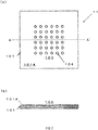
- FIG. 1(a) is a plan view showing one aspect of the biochip of the present invention (hereinafter also referred to as "Biochip (A)").
- Biochip (A) ring-shaped Boundary 102 is formed on Upper Surface 101A of Substrate 101.
- the above-described Boundary 102 is formed into an annular shape having a predetermined width, and is protruded from Substrate 101 to a predetermined height, so as to form Reaction Area 103 for retaining a liquid in a space surrounded by Upper Surface 101A and Boundary 102 of Substrate 101.
- a ring-shaped boundary is shown, but the shape of the boundary is not limited thereto, and various shapes such as oval and polygonal shapes (e.g., quadrangle, pentagon, hexagon, and octagon) may be adopted.
- Spot 104 on which a component reacting with the above-described test sample component (i.e., a material to be immobilized) is immobilized) is arranged.
- a plurality of the above-described Spots 104 can be arranged.
- a plurality of independent spots are arranged at predetermined positions with predetermined intervals.
- Figure 1(b) is a cross-sectional view showing a cross-sectional structure obtained by cutting Biochip (A) 10 with the line A-A' (see Figure 1(a) ).
- the lower limit of the height of Boundary 102 from Upper Surface 101A of Substrate 101 is not particularly limited, but it is preferably 1 mm or more, and more preferably 2 mm or more.
- the upper limit of the height of Boundary 102 from Upper Surface 101A of Substrate 101 is not particularly limited, either. Taking into consideration the intended use of the chip, it is preferably 10 mm or less.
- the width of Boundary 102 is not particularly, either.
- Boundary 102 is not particularly limited, as long as it does not affect the test sample or the biochemical reaction.
- the material can be appropriately selected from rubber compositions such as natural rubber, synthetic rubber, silicon rubber, fluorine rubber or urethane rubber, or resin materials that can be used as the above-described substrate.
- On Spot 104 the above-described material to be immobilized, or an immobilization carrier, on which the material to be immobilized has been immobilized, is immobilized.
- the number of Spots 104 or the arrangement thereof is not particularly limited, and any given number or arrangement can be applied.
- the lower limit of the number of Spots 104 is preferably 3 or more, more preferably 12 or more, and particularly preferably 18 or more.
- the upper limit of the number of Spots 104 is preferably 168 or less, and more preferably 144 or less.
- FIG. 2(a) is a plan view showing another aspect of the biochip of the present invention (hereinafter also referred to as "Biochip (B)").
- Biochip (B) 11 is different from Biochip (A) in that it does not have a boundary and the entire Upper Surface 101A of Substrate 101 serves as Reaction Area 103, but Biochip (B) 11 is identical to Biochip (A) in terms of other configurations. Since Biochip (B) does not need to establish a boundary, it is advantageous in terms of a simple production process and low production costs.
- FIG. 3(a) is a plan view showing one aspect of the biochip of the present invention (hereinafter also referred to as "Biochip (C)").
- Biochip (C) 12 ring-shaped Boundary 102 is formed on Upper Surface 101A of Substrate 101.
- the above-described Boundary 102 is formed into an annular shape having a predetermined width, and is protruded from Substrate 101 to a predetermined height, so as to form Reaction Area 103 for retaining a liquid in a space surrounded by Upper Surface 101A and Boundary 102 of Substrate 101.
- Coating Layer 104 is formed to prevent non-specific adsorption and to immobilize biological materials on the substrate, and a plurality of Spots 105, on which components reacting with the above-described test sample components (i.e., materials to be immobilized) have been immobilized, are arranged on the substrate via the Coating Layer 104.
- the above-described Spots 105 are arranged as a plurality of independent spots at predetermined positions with predetermined intervals.
- Figure 3(b) is a cross-sectional view showing a cross-sectional structure obtained by cutting Biochip (C) 12 with the line A-A' (see Figure 3(a) ).
- the lower limit of the height of Boundary 102 from Upper Surface 101A of Substrate 101 is not particularly limited, but it is preferably 1 mm or more, and more preferably 2 mm or more.
- the upper limit of the height of Boundary 102 from Upper Surface 101A of Substrate 101 is not particularly limited, either. Taking into consideration the intended use of the chip, it is preferably 10 mm or less.
- the width of Boundary 102 is not particularly, either.
- Boundary 102 is not particularly limited, as long as it does not affect the test sample or the biochemical reaction.
- the material can be appropriately selected from rubber compositions such as natural rubber, synthetic rubber, silicon rubber, fluorine rubber, or urethane rubber, or resin materials that can be used as the above-described substrate.
- the thickness of Coating Layer 104 is not particularly limited, and any given thickness can be formed.
- the thickness is preferably 1 nm to 10 ⁇ m, more preferably 2 nm to 1 ⁇ m, and particularly preferably 10 nm to 100 nm.
- On Spot 105 the above-described material to be immobilized, or an immobilization carrier, on which the material to be immobilized has been immobilized, is immobilized.
- the number of Spots 105 or the arrangement thereof is not particularly limited, and any given number or arrangement can be applied.
- the lower limit of the number of Spots 105 is preferably 3 or more, more preferably 12 or more, and particularly preferably 18 or more.
- the upper limit of the number of Spots 105 is preferably 168 or less, and more preferably 144 or less.
- FIG. 4(a) is a plan view showing another aspect of the biochip of the present invention (hereinafter also referred to as "Biochip (D)").
- Biochip (D) 13 is different from Biochip (C) in that Coating Layer 104 for preventing non-specific adsorption and immobilizing biological materials is formed on the entire upper surface of Substrate 101. Accordingly, ring-shaped Boundary 102 is formed on Coating Layer 104.
- the above-described Boundary 102 is formed into an annular shape having a predetermined width, and is protruded from Coating Layer 104 to a predetermined height, so as to form Reaction Area 103 for retaining a liquid in a space surrounded by Coating Layer 104 and Boundary 102.
- the cross-section of Boundary 102 in this aspect is a semi-cylindrical form.
- the cross-sectional shape of Boundary 102 is not particularly limited, as long as a liquid can be retained in the space surrounded by Boundary 102.
- various shapes such as a triangle, a trapezoidal shape, or an L-shape can be adopted, as well as a rectangle as in the case of Biochip A.
- a plurality of Spots 105, on which components reacting with the above-described test sample components (i.e., materials to be immobilized) have been immobilized, are arranged on Coating Layer 104 of the above-described Reaction Area 103.
- the above-described Spots 105 are arranged as a plurality of independent spots at predetermined positions with predetermined intervals.
- Figure 4(b) is a cross-sectional view showing a cross-sectional structure obtained by cutting Biochip (D) 13 with the line A-A' (see Figure 4(a) ).
- the range of the height of Boundary 102 from Coating Layer 104 is the same as the range of the height of Boundary 102 from Upper Surface 101A of Substrate 101 in Biochip (C).
- the width and material of Boundary 102, the thickness of Coating Layer 104, and Spots 105 are the same as those of Biochip (C).
- the method for producing the biochip of the present invention comprising a hydrophilic reaction area may comprise:
- Step 1-1 may comprise a step of performing a hydrophilization treatment on a substrate.
- the hydrophilization treatment of the substrate is not particularly limited, as long as it is a treatment of hydrophilizing the surface of the substrate.
- Examples of the hydrophilization treatment may include: a method comprising applying silica, a surfactant and the like that are dissolved or suspended in a liquid onto a substrate according to spin-coating, coating, spraying, immersion, etc., and then drying it; a method of performing a chemical hydrophilization treatment such as a plasma treatment, a UV-ozone treatment, a corona treatment, or a flame treatment on a substrate; a method of transcribing a fine nanostructure on a substrate, or roughening a substrate with a liquid medicine to physically form a nanostructure on the substrate, so as to impart hydrophilicity to the substrate; and a method of coating a substrate with a hydrophilic polymer.
- a chemical hydrophilization treatment such as a plasma treatment, a UV-ozone treatment, a corona treatment, or a flame treatment on a substrate, in which the chemical bonds of molecules on the resin surface are cleaved and thereby hydrophilic functional groups having polarity, such as OH (hydroxyl groups), CO (carbonyl groups), COOH (carboxyl groups), methoxy groups, peroxide groups, or
- a step of forming a boundary on a substrate to form a reaction area can be established.
- the method of forming a reaction area is not particularly limited. Examples of the method of forming a reaction area that can be used herein may include: a method of allowing a ring that has previously been formed with the above-described rubber composition or the above-described resin material to adhere to a substrate, using an adhesive or the like; and a method of subjecting a substrate constituted with the above-described resin material to various types of resin molding methods such as injection molding or vacuum forming, or to mechanical cutting or the like, so as to mold a ring.
- the adhesive used herein is not particularly limited, as long as it does not affect the test sample or the biochemical reaction. The adhesive can be appropriately selected from commercially available adhesives.
- Step 1-2 may comprise a step of spotting, at least, a material to be immobilized, a photocrosslinking agent having at least two photoreactive groups in a single molecule, and a thickener and/or a surfactant, in the form of grid-like spots, on above-described biochip substrate, and a step of applying a light to the substrate.
- the method for producing the biochip of the present invention having a coating layer and a reaction area surrounded by a boundary capable of retaining a liquid therein may comprise:
- Step 2-1 may comprise a step selected from a step of establishing a coating layer for preventing non-specific adsorption and immobilizing biological materials on the substrate and a step of forming a boundary on the substrate to form a reaction area.
- Step 2-1 comprises a step(s) selected from the above-described steps, the order of performing these steps may be changed.
- Step 2-1 may comprise a step of performing a surface treatment on the substrate, before the step of establishing a coating layer.
- the method of performing a surface treatment in the step of performing a surface treatment on the substrate is not particularly limited, as long as the method can enhance the adhesiveness between the substrate and the coating layer.
- a known surface modification method such as a plasma treatment, a UV-ozone treatment, or a corona treatment can be applied.
- a coating layer for preventing non-specific adsorption on a substrate and immobilizing biological materials on the substrate can be formed according to a known method such as the spin-coating, coating or spraying of a coating solution comprising a water-soluble polymer, or immersion of the substrate in a coating solution.
- the coating solution can be prepared by dissolving a water-soluble polymer in a solvent.
- solvents water, a lower alcohol that is mixed with water at any given ratio, and a mixture thereof can be used.
- methanol, ethanol, and isopropanol are preferable.
- the concentration of the polymer in the above-described coating solution is not particularly limited.
- the polymer concentration can be set at, for example, 0.0001 to 10 parts by mass, and preferably 0.001 to 1 part by mass.
- the concentration of the photocrosslinking agent can be set at, for example, 1 to 20 parts by mass, and preferably 2 to 10 parts by mass, with respect to the above-described polymer.
- the coating solution containing the above-described polymer preferably comprises a photocrosslinking agent having at least two photoreactive groups in a single molecule.
- the "photoreactive group” means a group that generates radicals as a result of light irradiation.
- photoreactive groups generate radicals as a result of light irradiation, so that covalent bonds can be formed with amino groups, carboxyl groups, carbon atoms constituting an organic compound, etc.
- a coating solution comprising the above-described photocrosslinking agent is applied onto the substrate, followed by light irradiation, so that the substrate can be bound to the polymer via the photocrosslinking agent, and so that a polymer layer having a non-specific adsorption preventing effect can be formed on the substrate.
- a photoreactive group and/or a group capable of covalently or coordinately binding to the substrate surface are introduced into the above-described polymer, so that the substrate can be bound to the polymer by utilizing the groups possessed by the polymer.
- the water-soluble polymer and the photocrosslinking agent comprised in the coating layer of the present invention are known.
- the water-soluble polymer and the photocrosslinking agent can be produced by known production methods and also, are commercially available.
- the film thickness of the above-described coating layer is not particularly limited, but it is preferably 1 nm to 10 ⁇ m, more preferably 2 nm to 1 ⁇ m, and particularly preferably 10 nm to 100 nm.
- the coating layer it is preferable to stabilize a coating layer by applying the coating layer to the substrate and then aging it under constant temperature and humidity conditions.
- the temperature is preferably 5°C to 40°C, and more preferably 20°C to 30°C.
- the humidity is preferably 40% to 80%, and more preferably 50% to 70%.
- the aging period is preferably 1 day to 1 month, and more preferably 3 days to 2 weeks.
- the method of forming a boundary on the substrate is not particularly limited.
- the adhesive is not particularly limited, as long as it does not affect the test sample or the biochemical reaction. Thus, an adhesive can be appropriately selected from commercially available adhesives.
- Step 2-2 may comprise: a step of spotting, at least, a material to be immobilized, a photocrosslinking agent having at least two photoreactive groups in a single molecule, and a thickener and/or a surfactant, in the form of grid-like spots, on the above-described biochip substrate; a step of applying a light to the substrate; and a step of removing unreacted components.
- a known immobilization method when the above-described material to be immobilized has previously been immobilized on an immobilization carrier, a known immobilization method can be applied.
- the immobilization method may be, for example, a method which comprises allowing the above-described magnetic microparticles used as immobilization carriers to react with the previously prepared materials to be immobilized in a solution such as an appropriately selected known buffer, and then recovering the magnetic microparticles on which the materials to be immobilized have been immobilized, but the immobilization method is not limited thereto.
- the above-described magnetic microparticles may have previously been washed with a known buffer, or when the magnetic microparticles on which the materials to be immobilized have been immobilized are recovered, the recovered magnetic microparticles may be washed with a known buffer.
- the photocrosslinking agent having at least two photoreactive groups in a single molecule, which is used in Step 1-2 or 2-2, is not particularly limited.
- the photoreactive groups possessed by the above-described photocrosslinking agent may include azide groups (-N3), acetyl groups, benzoyl groups and diazirine groups.
- azide groups are preferable because when the azide groups are irradiated with light, nitrogen molecules are dissociated and nitrogen radicals are generated, and these nitrogen radicals can bind not only to functional groups such as amino groups or carboxyl groups, but can also bind to carbon atoms constituting an organic compound, and can form covalent bonds with almost all organic matters.
- the photocrosslinking agent having such azide groups may be, for example, diazidostilbene.
- the photocrosslinking agent is preferably a water-soluble agent.
- the "water solubility" of the photocrosslinking agent means that an aqueous solution comprising the photocrosslinking agent in a concentration of 0.5 mM or more, and preferably 2 mM or more, can be given.
- the above-described material to be immobilized, or an immobilization carrier on which the material to be immobilized has been immobilized, and the above-described photocrosslinking agent are preferably dispersed or dissolved in a solution.
- the solution is not particularly limited, and a known buffer can be used.
- the buffer composition may include a PBS buffer, a HEPES buffer, a Tris buffer, and a MES buffer.
- a phosphate buffered saline is preferably used.
- a HEPES buffer is preferably used to prevent agglutination of the immobilization carrier.
- the solution, in which the material to be immobilized and the photocrosslinking agent are dispersed or dissolved may be referred to as a stamp solution at times.
- the concentration of the above-described material to be immobilized is not particularly limited.
- the concentration of the material to be immobilized is preferably 0.05 mg/mL to 2 mg/mL, and more preferably 0.1 mg/mL to 1 mg/mL.
- the material to be immobilized is allowed to react with the immobilization carrier in the concentration of the material to be immobilized that is preferably 0.5 mg/mL to 50 mg/mL, and more preferably 1 mg/mL to 25 mg/mL.
- the immobilization carrier, on which the material to be immobilized has been immobilized is used in a concentration of preferably 1 mg/mL to 10 mg/mL, and more preferably 2.5 mg/mL to 7.5 mg/mL.
- the concentration of the above-described photocrosslinking agent is not particularly limited, but it is preferably 0.01 mg/mL to 1 g/mL, and more preferably 0.2 mg/mL to 0.2 g/mL.
- the solution in which the above-described material to be immobilized, or the immobilization carrier on which the material to be immobilized has been immobilized, and the above-described photocrosslinking agent are dispersed or dissolved, preferably may further comprise a thickener and/or a surfactant.
- a thickener By allowing the above-described solution to comprise a thickener, the size of a spot can be controlled when the solution is spotted on a biochip substrate. More specifically, when a solution having a predetermined volume is spotted on a substrate, as the concentration of a thickener in the solution increases, the size of a spot (the area of a spot contacted with the substrate) tends to decrease.
- a phenomenon whereby the material to be immobilized accumulates in the gas-liquid interface and the material to be immobilized is thereby localized in the margin of the spot, can be prevented.
- a surfactant contributes to the improvement of the affinity for the substrate.
- the above-described thickener is not particularly limited, as long as it does not affect the test sample or the biochemical reaction.
- a commercially available thickener can be used.
- the thickener may include celluloses and derivatives thereof, polysaccharides, vinyl compounds, vinylidene compounds, polyglycol compounds, polyvinyl alcohol compounds, and polyalkylene oxide compounds.
- thickener may include gellan gum, xanthan gum, curdlan, pullulan, a guar gum derivative, locust bean gum, carrageenan, pectin, ⁇ glucan, tamarind gum, psyllium seed gum, dextran, glycerin, carboxymethyl cellulose, hydroxyethyl cellulose, hydroxymethylpropyl cellulose, lanolin, methyl cellulose, Vaseline, polyethylene glycol, polyvinyl alcohol, polyvinyl pyrrolidone, a carboxyl vinyl polymer, polyvinyl pyrrolidone, polyvinyl alcohol, a dextrin acid fatty ester, and an inulin acid fatty ester. It is preferable to use one or more selected from hydroxyethyl cellulose, methyl cellulose, polyvinyl pyrrolidone, and polyvinyl alcohol, and it is more preferable to use polyvinyl alcohol.
- the concentration of the above-described thickener is not particularly limited.
- polyvinyl alcohol when used as a thickener, it is used in a concentration of preferably 0.01 part by weight to 1 part by weight, more preferably 0.02 parts by weight to 0.5 parts by weight, and particularly preferably 0.03 parts by weight to 0.3 parts by weight, with respect to 100 parts by weight of the above-described solution.
- the above-described surfactant is not particularly limited, as long as it does not affect the test sample or the biochemical reaction.
- a commercially available nonionic surfactant can be used.
- the surfactant that can be used herein may include polyoxyethylene(10) octylphenyl ether [Triton X-100], polyoxyethylene(8) octylphenyl ether [Triton X-114], polyoxyethylene sorbitan monolaurate [Tween 20], polyoxyethylene sorbitan monooleate [Tween 80], polyoxyethylene(23) lauryl ether [Brij35], polyoxyethylene(20) lauryl ether [Brij58], Pluronic F-68, polyethylene glycol, and a mixture consisting of two or more types thereof. It is preferable to use one or more types selected from Triton X-100, Tween 20, and Tween 80, and it is more preferable to use Tween 20.
- the concentration of the above-described surfactant is not particularly limited.
- Tween 20 when used as a surfactant, it is used in a concentration of preferably 0.001 part by weight to 1 part by weight, more preferably 0.005 parts by weight to 0.5 parts by weight, and particularly preferably 0.01 part by weight to 0.3 parts by weight, with respect to 100 parts by weight of the above-described solution.
- the viscosity of the stamp solution is not particularly limited, as long as a spot having a desired shape can be formed.
- the viscosity of the stamp solution at 25°C may be, for example, 0.4 mPa ⁇ s to 40 mPa ⁇ s, preferably 0.5 mPa ⁇ s to 10 mPa ⁇ s, more preferably 0.6 mPa ⁇ s to 4 mPa ⁇ s, particularly preferably 0.8 mPa ⁇ s to 2 mPa ⁇ s, and further particularly, approximately 1.3 mPa ⁇ s.
- the viscosity of the stamp solution at 25°C may be 0.6 mPa ⁇ s to 10 mPa ⁇ s, 0.8 mPa ⁇ s to 4 mPa ⁇ s, 1.0 mPa ⁇ s to 2 mPa ⁇ s, 1.12 mPa ⁇ s to 2 mPa ⁇ s, 1.13 mPa ⁇ s to 2 mPa ⁇ s, 1.14 mPa ⁇ s to 2 mPa ⁇ s, 1.15 mPa ⁇ s to 2 mPa ⁇ s, 1.16 mPa ⁇ s to 2 mPa ⁇ s, 1.17 mPa ⁇ s to 2 mPa ⁇ s, 1.18 mPa ⁇ s to 2 mPa ⁇ s, 1.19 mPa ⁇ s to 2 mPa ⁇ s, 1.2 mPa ⁇ s to 2 mPa ⁇ s, or the like.
- the method of spotting a material to be immobilized or an immobilization carrier on which a material to be immobilized has been immobilized, and a photocrosslinking agent, onto the above-described biochip substrate is not particularly limited.
- a method of spotting them using a micropipette or the like, a spotting method involving a pin method, a spotting method involving a piezoelectric method, etc. can be applied.
- a spotting method of using a micropipette or the like and a spotting method involving a pin method, which are not restricted by the size of a microparticle are preferable.
- the diameter of such a spot can be set at, for example, 400 ⁇ m to 800 ⁇ m, and preferably 500 ⁇ m to 700 ⁇ m.
- Immobilization of a material to be immobilized, or an immobilization carrier on which a material to be immobilized has been immobilized can be carried out by applying a light to a substrate, after application of a solution onto the substrate, preferably after the drying of the applied solution.
- the light is not particularly limited, as long as the used photoreactive groups can generate radicals under the light.
- ultraviolet rays for example, with a wavelength of 10 to 400 nm
- the irradiation time can be set at, for example, 10 seconds to 120 minutes, preferably 30 seconds to 60 minutes, and more preferably 1 minute to 30 minutes.
- the irradiation time is almost equal to the time required for immobilization.
- the dose of the irradiated light is not particularly limited, but it is generally approximately 1 mW to 100 mW per cm 2 .
- the photoreactive groups contained in the photocrosslinking agent (or when the polymer has photoreactive groups, the photoreactive groups contained in the polymer) generate radicals as a result of the light irradiation.
- the polymer layer can be bound to the material to be immobilized via the photocrosslinking agent.
- the polymer layer can be bound to the material to be immobilized and/or the immobilization carrier via the photocrosslinking agent.
- the substrate is washed according to a known method, so that unreacted components and the like can be removed.
- washing is not essential, and the immobilized material may be subjected to productization, while the stamp solution remains.
- a biochip on which a desired material to be immobilized has been immobilized, can be obtained.
- stamp solution components such as a thickener and/or a surfactant, may adhere onto the spot on the biochip.
- stamp solution residue can be removed by washing the biochip, as appropriate, before the use thereof.
- a deoxygenation means is performed on a material to be immobilized, which is affected by oxidation, in particular, amino acids in a protein, etc., so as to obtain the effect of preventing the oxidation of the material to be immobilized and/or the effect of suppressing the proliferation of aerobic bacteria and fungi on the biochip.
- Examples of the deoxygenation means may include, but are not limited to, the packaging of the biochip by at least one form of the following (a) to (d): (a) vacuum packaging; (b) packaging together with inert gas; (c) packaging together with an oxygen scavenger; and (d) packaging with a wrapping material having deoxygenation function.
- examples of the deoxygenation means may also include a combination of (a) and (c) (i.e., vacuum packaging together with an oxygen scavenger), a combination of (b) and (c) (i.e., packaging together with inert gas and an oxygen scavenger), and a combination of (b) to (d) (i.e., packaging with a wrapping material having deoxygenation function, together with inert gas and an oxygen scavenger), in addition to each of the above packaging forms (a) to (d).
- a) and (c) i.e., vacuum packaging together with an oxygen scavenger
- a combination of (b) and (c) i.e., packaging together with inert gas and an oxygen scavenger
- a combination of (b) to (d) i.e., packaging with a wrapping material having deoxygenation function, together with inert gas and an oxygen scavenger
- Such a deoxygenation means may include a method of performing the replacement of inert gas such as nitrogen or argon upon the aforementioned packaging of a biochip, a method of enclosing an oxygen scavenger in a package, and a method of using a wrapping material having deoxygenation function, for example, a wrapping material film.
- oxygen scavenger allowed to coexist in the package may include: inorganic oxygen scavengers such as iron or cerium oxide; and organic oxygen scavengers.
- inorganic oxygen scavengers such as iron or cerium oxide
- organic oxygen scavengers Such an oxygen scavenger is not particularly limited, and specific examples may include commercially available oxygen scavengers that can be used for medical purposes, such as "AGELESS” manufactured by MITSUBISHI GAS CHEMICAL COMPANY, INC., and "PharmaKeep” manufactured by MITSUBISHI GAS CHEMICAL COMPANY, INC.
- the wrapping material having deoxygenation function is not particularly limited, and a wrapping film containing an oxygen scavenger is preferable.
- a wrapping film can be specifically classified into wrapping films containing an inorganic oxygen scavenger such as iron or cerium oxide, and wrapping films containing an organic oxygen scavenger. These films are not particularly limited.
- Examples of the wrapping film may include commercially available films that can be used for medical purposes, for example, wrapping materials for wrapping cerium oxide, such as "OxyCatch" manufactured by Kyodo Printing Co., Ltd., and "High Star 02" manufactured by Starplastic Industry Inc.
- wrapping materials for wrapping ion may include "AGELESS OMAC” manufactured by MITSUBISHI GAS CHEMICAL COMPANY, INC., and “OxyGuard” manufactured by Toyo Seikan Co., Ltd.
- the biochip of the present invention can stably maintain the material to be immobilized thereon by the combined use of a desiccant in some cases.
- a desiccant it is preferable to use a desiccant in combination.
- a desiccant a desiccant that is commonly used in the field of pharmaceutical products can be used.
- the present invention also relates to a package that packages a biochip according to the above-described preservation method.
- the package of the present invention may package the biochip of the present invention by at least one form of the following (a) to (d): (a) vacuum packaging; (b) packaging together with inert gas; (c) packaging together with an oxygen scavenger; and (d) packaging with a wrapping material having deoxygenation function.
- the package of the present invention may further enclose a desiccant.
- the above-described individual configurations regarding the package of the present invention are as described above regarding the preservation method of the present invention.
- the package of the present invention can preserve the biochip of the present invention for a long period of time without impairing the quality of the biochip of the present invention, and thus, it is excellent in terms of practicality.
- the present invention also relates to a method of testing a biological sample by using the above-described biochip, a method of testing the health condition of a subject, a method of testing or diagnosing a disease in a subject, the above-described biochip for use in such inspection and/or diagnostic application, and a kit for use in inspection and/or diagnostic application, comprising the above-described biochip.
- the method of testing a biological sample by using the biochip of the present invention comprises:
- target substance may include, but are not limited to, proteins such as antibodies, antigens, enzymes, hormones or cytokines, nucleic acid molecules such as RNA or DNA, and sugar chains.
- the material reacting with the target substance is not limited, and examples of the material may include antigens, antibodies, aptamers, lectins, polynucleotides, enzymes, and substrates.
- the reaction of the material to be immobilized with the target substance can be detected by various types of known means.
- the target substance is a protein
- the protein is allowed to react with a labeled antibody reacting against the protein, and then, the label of the labeled antibody binding to the protein can be detected by a method suitable for detection of the label.
- the target substance is a nucleic acid molecule
- the nucleic acid molecule is allowed to react with a labeled probe hybridizing with the nucleic acid molecule, and then, the label of the labeled probe binding to the nucleic acid molecule can be detected by a method suitable for detection of the label.
- Examples of the label may include, but are not limited to, a fluorescent material, a luminescent material, an enzyme, and a radioisotope.
- Examples of the method of detecting the label may include, but are not limited to, spectrophotometry, absorptiometry, fluorometry, colorimeteric method, and autoradiography. The detection may be either qualitative detection or quantitative detection. When quantitative detection is carried out, information regarding the concentration of a target substance in a biological sample, etc. can be obtained.
- the method of testing the health condition of a subject by using the biochip of the present invention comprises:
- Examples of the information regarding health condition may include fatigue, stress, and nutritional status.
- Examples of the target substance may include biological materials regarding the information, such as proteins, nucleic acid molecules, or sugar chains.
- Examples of the material to be immobilized may include materials reacting with these biological materials, such as antigens, antibodies, aptamers, lectins, polynucleotides, enzymes, or substrates. Biomarkers used as indicators for fatigue, stress, nutritional status, etc. have been known.
- the method of testing or diagnosing a disease in a subject by using the biochip of the present invention comprises:
- the disease may be a disease that can be tested and/or diagnosed by detecting a substance in the biological sample.
- the disease may include, but are not limited to, allergic disease, endocrine disease, infectious disease, disease with genetic abnormality, inflammatory disease, autoimmune disease, and neoplastic disease.
- the target substance may include biological materials regarding such diseases, such as proteins, nucleic acid molecules, or sugar chains.
- the material to be immobilized may include materials reacting with these biological materials, such as antigens, antibodies, aptamers, lectins, polynucleotides, enzymes, or substrates.
- Various types of disease markers such as a tumor marker, an infectious disease marker, a genetic disease marker, an endocrine disease marker, or an inflammation marker have been known.
- the biochip of the present invention can be used in each of the above-described intended uses, namely, inspection of a biological sample, inspection of the health condition of a subject (e.g., fatigue, stress, nutritional status, etc.), and inspection or diagnosis of a disease in a subject (e.g., allergic disease, endocrine disease, infectious disease, disease with genetic abnormality, inflammatory disease, autoimmune disease, neoplastic disease, etc.).
- the biochip of the present invention for use in each of the above-described intended uses preferably comprises a material to be immobilized that is suitable for each of the above-described intended uses.
- the kit of the present invention can be used in each of the above-described intended uses, namely, inspection of a biological sample, inspection of the health condition of a subject (e.g., fatigue, stress, nutritional status, etc.), and inspection or diagnosis of a disease in a subject (e.g., allergic disease, endocrine disease, infectious disease, disease with genetic abnormality, inflammatory disease, autoimmune disease, neoplastic disease, etc.).
- the kit of the present invention includes the biochip of the present invention, and preferably the biochip of the present invention comprising a material to be immobilized that is suitable for each of the above-described intended uses.
- the kit of the present invention may include a reagent for detecting the reaction of the material to be immobilized with a target substance contained in a biological sample, a standard sample, instructions showing the method of using the kit, etc. such as, for example, an instruction manual, and a medium recording information regarding the use method, such as, for example, a flexible disc, CD, DVD, a Blu-ray disc, a memory card, or an USB memory, as well as the biochip of the present invention.
- a polycarbonate sheet (manufactured by MITSUBISHI GAS CHEMICAL COMPANY, INC., MU58U, thickness: 0.8 mm) was irradiated with ultraviolet rays, using a UV-ozone irradiation device (manufactured by SEN LIGHTS Co., Ltd., SSP16-110, UV lamp: SUV110GS-36L) at an irradiation distance of 50 mm for 2 minutes.
- a polyethylene glycol monomethacrylate polymer manufactured by Sanyu Chemical Co., Ltd.; the molecular weight of a polyethylene glycol moiety: 350
- 4,4'-diazidostilbene-2,2'-disulfonic acid manufactured by TOKYO CHEMICAL INDUSTRY CO., LTD.; 98%; hereinafter referred to as "bisazide"
- bisazide 4,4'-diazidostilbene-2,2'-disulfonic acid
- the above-described UV-irradiated polycarbonate was coated with 15 ⁇ L of this coating solution under conditions of 800 rpm for 5 seconds, and 5000 rpm for 10 seconds.
- a UV irradiation device manufactured by UVP, CL-1000
- the substrate was irradiated with ultraviolet rays at 120 mW/cm 2 for 10 minutes.
- a silicon rubber-made O ring (14 ⁇ ) was adhered to the thus coated substrate, using an adhesive, so as to form a reaction area.
- the aging operation was performed at a temperature of 25°C at a humidity of 65% for 4 days, so as to obtain Biochip Substrate 1.
- Biochip Substrate 2 was obtained in the same manner as that for Biochip Substrate 1, with the exception that a reaction area was not formed with a silicon rubber.
- Sodium chloride, potassium chloride, disodium hydrogen phosphate dodecahydrate, and potassium dihydrogen phosphate were each dissolved in ultrapure water to result in 0.8 parts by weight, 0.02 parts by weight, 0.29 parts by weight, and 0.02 parts by weight, respectively, so as to obtain a PBS solution.
- 4-(2-hydroxyethyl)-1-piperazineethanesulfonic acid was dissolved in ultrapure water to result in 0.59 parts by weight, so as to obtain a HEPES solution.
- Polyvinyl alcohol manufactured by Wako Pure Chemical Industries, Ltd., 160-03055
- Tween 20 manufactured by Sigma-Aldrich, P7949-100ML
- Streptavidin beads manufactured by TAMAGAWA SEIKI Co., Ltd.
- stamp Solution 1-1 The viscosity of Stamp Solution 1-1 was measured. The measurement was carried out using B-type Viscometer DV2T (manufactured by Brookfield) under conditions of 20°C and 200 rpm. Before the measurement of a sample, correction was carried out using water and a standard liquid for calibrating viscometer JS2.5 (manufactured by NIPPON GREASE Co., Ltd.). The measurement was carried out three times, and a mean value thereof was then obtained. As a result, the viscosity of Stamp Solution 1-1 was measured to be 1.31 mPa ⁇ s.
- Stamp Solution 1-2 was obtained in the same manner as that for Stamp Solution 1-1, with the exception that polyvinyl alcohol was not added to the solvent for stamp solution.
- the viscosity of Stamp Solution 1-2 was obtained in the same manner as that for Stamp Solution 1-1.
- the viscosity of Stamp Solution 1-2 was measured to be 1.21 mPa ⁇ s.
- Stamp Solution 1-3 was obtained in the same manner as that for Stamp Solution 1-1, with the exception that Tween 20 was not added to the solvent for stamp solution.
- the viscosity of Stamp Solution 1-3 was obtained in the same manner as that for Stamp Solution 1-1.
- the viscosity of Stamp Solution 1-3 was measured to be 1.22 mPa ⁇ s.
- Stamp Solution 1-4 was obtained in the same manner as that for Stamp Solution 1-1, with the exception that polyvinyl alcohol and Tween 20 were not added to the solvent for stamp solution.
- the viscosity of Stamp Solution 1-4 was obtained in the same manner as that for Stamp Solution 1-1.
- the viscosity of Stamp Solution 1-4 was measured to be 1.11 mPa ⁇ s.
- Morpholineethanesulfonic acid monohydrate was dissolved in ultrapure water to result in 0.53 parts by weight, so as to obtain a MES solution.
- Polyvinyl alcohol manufactured by Wako Pure Chemical Industries, Ltd., 160-03055
- Tween 20 manufactured by Sigma-Aldrich, P7949-100ML
- HEPES solution was dissolved in the HEPES solution to result in 0.1 part by weight and 0.05 parts by weight, respectively, thereby obtaining a solvent for stamp solution.
- stamp Solution 1-5 ⁇ s1-Casein (manufactured by Sigma-Aldrich, C6780-250MG) used as a material to be immobilized was allowed to react with Linker beads (manufactured by TAMAGAWA SEIKI Co., Ltd.) in the MES buffer at 40°C for 20 hours, and was then purified. The resulting solution was dispersed in the solvent for stamp solution, so as to obtain Stamp Solution 1-5.
- Linker beads manufactured by TAMAGAWA SEIKI Co., Ltd.
- Stamp Solution 1-6 was obtained in the same manner as that for Stamp Solution 1-5, with the exception that polyvinyl alcohol was not added to the solvent for stamp solution.
- Stamp Solution 1-7 was obtained in the same manner as that for Stamp Solution 1-5, with the exception that Tween 20 was not added to the solvent for stamp solution.
- Stamp Solution 1-8 was obtained in the same manner as that for Stamp Solution 1-5, with the exception that polyvinyl alcohol and Tween 20 were not added to the solvent for stamp solution.
- Stamp Solution 1-10 was obtained in the same manner as that for Stamp Solution 1-9, with the exception that polyvinyl alcohol was not added to the solvent for stamp solution.
- Stamp Solution 1-11 was obtained in the same manner as that for Stamp Solution 1-9, with the exception that Tween 20 was not added to the solvent for stamp solution.
- Stamp Solution 1-12 was obtained in the same manner as that for Stamp Solution 1-9, with the exception that polyvinyl alcohol and Tween 20 were not added to the solvent for stamp solution.
- stamp Solution Material to be immobilized Immobilization carrier Immobilization solution Reaction conditions
- Solvent for stamp solution 1-1 Biotinylated peptide Streptavidin beads PBS buffer 4°C 1.5 hours HEPES-PVA-Tween 1-2 Biotinylated peptide Streptavidin beads PBS buffer 4°C 1.5 hours HEPES- Tween 1-3 Biotinylated peptide Streptavidin beads PBS buffer 4°C 1.5 hours HEPES-PVA 1-4 Biotinylated peptide Streptavidin beads PBS buffer 4°C 1.5 hours HEPES 1-5 ⁇ s1-casein Linker beads 25 mM MES buffer 40°C 20 hours HEPES-PVA- Tween 1-6 ⁇ s1-casein Linker beads 25 mM MES buffer 40°C 20 hours HEPES- Tween 1-7 ⁇ s1-casein Linker beads 25 mM MES buffer 40°C
- Bisazide was dissolved in ultrapure water to prepare a 10 mg/mL bisazide solution.
- the 10 mg/mL bisazide solution was diluted by 5 times (Bisazide Solution A), or by 5000 times (Bisazide Solution B).
- Bisazide Solution B was dissolved in each of Stamp Solutions 1-1 to 1-8 to result in 4.8 parts by weight of the Bisazide Solution B.
- Bisazide Solution A was dissolved in each of Stamp Solutions 1-9 to 1-12 to result in 4.8 parts by weight of the Bisazide Solution A.
- the thus obtained 12 types of stamp solutions were each spotted on Biochip Substrate 1 or 2 produced in Example 1, in an amount of 3 spots per stamp solution (6 x 6, 36 spots in total), according to a lattice point-type multipoint dispensing spot method (in the order from Stamp Solution 1-12 to Stamp Solution 1-1).
- the diameter of a spot was 0.36 to 0.54 ⁇ m, and the distance between spots was approximately 1.1 mm.
- the spots were dried using a vacuum dryer at 0.09 MPa for 10 minutes.
- the spots were irradiated with ultraviolet rays, using a UV irradiation device (manufactured by UVP, CL-1000) at 120 mW/cm 2 for 10 minutes, so as to obtain Biochip 1 or 2.
- Example 3 an IgG antibody contained in casein-positive human serum (PlasmaLab) was measured.
- the chip was washed with a TBS-T solution (137 mM sodium chloride, 2.68 mM potassium chloride, 25 mM tris-hydroxymethylaminomethane, pH 7.4, 0.1% by weight of Tween 20) three times.
- TBS-T solution 137 mM sodium chloride, 2.68 mM potassium chloride, 25 mM tris-hydroxymethylaminomethane, pH 7.4, 0.1% by weight of Tween 20
- 130 ⁇ L of 8-fold diluted serum was added as a test sample, and while shaking, it was reacted at room temperature for 8 minutes.
- the test sample was aspirated and was then washed with a TBS-T solution.
- an anti-human IgG antibody manufactured by SeraCare Lifesciences, Inc., 0751-1004 that had been 2000 times diluted with Can Get Signal Immunoreaction Enhancer Solution 2 (manufactured by TOYOBO CO., LTD., NKB-301) was added to the resultant, and while shaking, the mixture was reacted at room temperature for 4 minutes. Thereafter, the antibody was aspirated and was then washed with TBS-T. To the resultant, 130 ⁇ L of a luminescent reagent (Dynalight Substrate with Rapid Glow Enhancer, Molecular Probes, 4475406) was added, and the thus obtained mixture was then shaken for 1 minute.
- a luminescent reagent Dynalight Substrate with Rapid Glow Enhancer, Molecular Probes, 4475406
- Table 2 Luminescence signal intensity measured using biochip Spot Stamp Solution Luminescence intensity 1 1-1 8243 2 1-2 6242 3 1-3 6978 4 1-4 7872 5 1-5 138073 6 1-6 128667 7 1-7 70302 8 1-8 73783 9 1-9 29030 10 1-10 28050 11 1-11 8814 12 1-12 11767 Table 3 Average volume of solid matter immobilized on each spot Spot Stamp Solution Average volume ( ⁇ m 3 ) 1 1-1 40613 2 1-2 34995 3 1-3 28852 4 1-4 24000 5 1-5 121800 6 1-6 109173 7 1-7 63455 8 1-8 40006
- the biochip of the present invention enables analysis with an extremely small amount of test sample (16 ⁇ L). Further, according to the method for producing a biochip of the present invention, the binding site of a material to be immobilized can be controlled, and a biochip having a stable spot shape can be obtained.
- Stamp Solutions 2-1 to 2-8 were prepared in the same manner as that of Example 2, with the exceptions that Streptavidin Mag Sepharose (manufactured by GE Healthcare) was used instead of Streptavidin beads, and Sera-Mag Carboxylate-Modified Magnetic Particles (Hydrophylic) (manufactured by GE Healthcare) were used instead of Linker beads.
- Conditions for preparation of each stamp solution were summarized in Table 4. Besides, in the table, immobilization carrier "A” indicates Streptavidin Mag Sepharose, and immobilization carrier "B” indicates Sera-Mag Carboxylate-Modified Magnetic Particles.
- stamp Solution Material to be immobilized Immobilization carrier Immobilization reaction solution Reaction conditions Solvent for stamp solution 2-1 Biotinylated peptide A PBS buffer 4°C 1.5 hours HEPES-PVA- Tween 2-2 Biotinylated peptide A PBS buffer 4°C 1.5 hours HEPES- Tween 2-3 Biotinylated peptide A PBS buffer 4°C 1.5 hours HEPES-PVA 2-4 Biotinylated peptide A PBS buffer 4°C 1.5 hours HEPES 2-5 ⁇ s1-casein B 25 mM MES buffer 40°C 20 hours HEPES-PVA- Tween 2-6 ⁇ s1-casein B 25 mM MES buffer 40°C 20 hours HEPES- Tween 2-7 ⁇ s1-casein B 25 mM MES buffer 40°C 20 hours HEPES-PVA 2-8 ⁇ s1-casein B 25 mM MES buffer 40°C 20 hours HEPES-PVA 2-8 ⁇ s1-
- Stamp Solutions 2-1 to 2-8 and 1-9 to 1-12 were each spotted on Biochip Substrate 1 or 2 produced in Example 1 in the same manner as that of Example 3, and thereafter, drying and UV irradiation were also carried out in the same manner as that of Example 3, so as to obtain Biochip 3 or 4.
- the same measurement as in Example 4 was carried out.
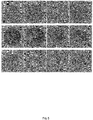
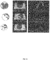
- the image of luminescence intensity is shown in Figure 15
- luminescence signal intensity obtained from the image of Figure 15 is shown in Table 5. Observation was also carried out using an optical microscope and a laser microscope, and the same results as those of Example 4 were obtained.
- Sodium chloride, potassium chloride, disodium hydrogen phosphate dodecahydrate, and potassium dihydrogen phosphate were each dissolved in ultrapure water to result in 0.8 parts by weight, 0.02 parts by weight, 0.29 parts by weight, and 0.02 parts by weight, respectively, so as to obtain a PBS solution.
- Morpholineethanesulfonic acid monohydrate was dissolved in ultrapure water to result in 0.53 parts by weight, so as to obtain a MES solution.
- t-Butyl alcohol manufactured by Wako Pure Chemical Industries, Ltd., 028-03386
- dimethyl sulfoxide at a volume ratio of 4 : 1
- Tris[(1-benzyl-1H-1,2,3-triazol-4-yl)methyl]amine manufactured by Sigma-Aldrich, 678937-50MG
- ⁇ s1-casein manufactured by Sigma-Aldrich, C6780-250MG
- ⁇ -casein manufactured by Sigma-Aldrich, C6905-250MG
- ⁇ -lactalbumin manufactured by Sigma-Aldrich, L5385-25MG
- ⁇ -lactoglobulin manufactured by Sigma-Aldrich, L3908-250MG
- ovomucoid manufactured by Sigma-Aldrich, T2011-250MG
- ovalbumin manufactured by Sigma-Aldrich, A2512-250MG
- the materials to be immobilized were each dissolved in Solution A, so as to obtain Stamp Solutions 3-1 to 3-6.
- As materials to be immobilized ⁇ s1-casein, ⁇ -lactalbumin, and ovomucoid were each allowed to react with Linker beads in a MES buffer at 40°C for 20 hours, and were then purified, followed by dispersion in Solution B, so as to obtain Stamp Solutions 3-7 to 3-9.
- Biotinylated Peptide A and Biotinylated Peptide B which had been formed by biotinylating the termini of different Partial Peptides A and B of ⁇ s1-casein (each consisting of 15 amino acid residues), were each allowed to react with Streptavidin beads in a PBS solution at 4°C for 1.5 hours, and were then purified, followed by dispersion in Solution B, so as to obtain Stamp Solutions 3-11 and 3-12.
- Azidated Peptide A and Azidated Peptide B which had been formed by azidating the termini of the Peptides A and B, were each allowed to react with Alkyne beads (manufactured by TAMAGAWA SEIKI Co., Ltd.) in a HEPES solution at 25°C for 20 hours, and were then purified, followed by dispersion in Solution B, so as to obtain Stamp Solutions 3-13 and 3-14. Conditions for preparation of each stamp solution were summarized in Table 6.
- Bisazide was dissolved in ultrapure water to prepare a 10 mg/mL bisazide solution.
- the 10 mg/mL bisazide solution was diluted by 5 times (Bisazide Solution A), or by 5000 times (Bisazide Solution B).
- Bisazide Solution A was dissolved in each of Stamp Solutions 3-1 to 3-6 to result in 4.8 parts by weight of the Bisazide Solution A.
- Stamp Solutions 3-7 to 3-14 beads were dispersed in each of the stamp solutions, and Bisazide Solution B was then dissolved therein to result in 4.8 parts by weight of the Bisazide Solution B.
- the thus obtained 14 types of stamp solutions were each spotted on Biochip Substrate 1 produced in Example 1, in an amount of 3 spots per stamp solution (6 x 7, 42 spots in total), according to a lattice point-type multipoint dispensing spot method. After completion of the spotting, the spots were dried using a vacuum dryer at 0.09 MPa for 10 minutes.
- the spots were irradiated with ultraviolet rays, using a UV irradiation device (manufactured by UVP, CL-1000) at 120 mW/cm 2 for 10 minutes, so as to obtain Biochip 3.
- a UV irradiation device manufactured by UVP, CL-1000
- the produced Biochip 3 was preserved under the following conditions.
- a polycarbonate sheet (manufactured by MITSUBISHI GAS CHEMICAL COMPANY, INC., MR58U, thickness: 0.8 mm) was irradiated with ultraviolet rays, using a UV-ozone irradiation device (manufactured by SEN LIGHTS Co., Ltd., SSP16-110, UV lamp: SUV110GS-36L) at an irradiation distance of 50 mm for 2 minutes, so that the entire upper surface of the sheet was hydrophilized. Using an adhesive, a silicon rubber-made O ring (14 ⁇ ) was adhered to the hydrophilized sheet to form a reaction area, so as to obtain Biochip Substrate 1.
- Biochip Substrate 2 was obtained in the same manner as that for Substrate 1, with the exception that the treatment using a UV-ozone irradiation device was carried out for 1 minute.
- Biochip Substrate 3 was obtained in the same manner as that for Substrate 1, with the exception that the treatment using a UV-ozone irradiation device was carried out for 30 seconds.
- Biochip Substrate 4 was obtained in the same manner as that for Substrate 1, with the exception that the treatment using a UV-ozone irradiation device was carried out for 8 minutes.
- Biochip Substrate 5 was obtained in the same manner as that for Substrate 1, with the exceptions that a desktop semi-automatic atmospheric pressure plasma surface reforming device (manufactured by Well, MyPL-Auto100) was used instead of the UV-ozone irradiation device, and that the treatment was carried out once at 100 W and at 50 mm/sec.
- a desktop semi-automatic atmospheric pressure plasma surface reforming device manufactured by Well, MyPL-Auto100
- Biochip Substrate 6 was obtained in the same manner as that of Example 1, with the exceptions that the UV-ozone treatment was not carried out.
- Polyethylene glycol monomethacrylate manufactured by Sanyu Chemical Co., Ltd.; the molecular weight of polyethylene glycol moiety: 350
- 4,4'-diazidostilbene-2,2'-disulfonic acid manufactured by TOKYO CHEMICAL INDUSTRY CO., LTD.; 98%; hereinafter referred to as "bisazide"
- bisazide 4,4'-diazidostilbene-2,2'-disulfonic acid
- a polycarbonate sheet was coated with 15 ⁇ L of the above-prepared coating solution, using a spin-coater (manufactured by MIKASA, MS-A100), under conditions of 800 rpm for 5 seconds and 5000 rpm for 10 seconds. Thereafter, using a UV irradiation device (manufactured by UVP, CL-1000), the sheet was irradiated with ultraviolet rays at 120 mW/cm 2 for 10 minutes, so that bisazide was crosslinked to form a coating layer of a non-specific adsorption preventing agent. With these exceptions, Biochip Substrate 7 was obtained in the same manner as that for Substrate 1.
- Functional groups on the surface of the resin were measured using an infrared spectrophotometer (manufactured by JASCO Corporation, FT/IR-4200).
- the contact angle is indicated as a mean value of the contact angles measured at three sites.
- a first measurement point the central portion of the sample was selected, and as second and third measurement points, two points, which were 20 mm or more apart from the first measurement point and were at positions point-symmetric to the first measurement point, were selected.
- stamp Solutions 3-1 to 3-14 prepared in Example 6 14 types were each spotted on Biochip Substrates 1 to 7, in an amount of 3 spots per stamp solution (6 x 7, 42 spots in total), according to a lattice point-type multipoint dispensing spot method. After completion of the spotting, the spots were dried using a vacuum dryer at 0.09 MPa for 10 minutes.
- the spots were irradiated with ultraviolet rays, using a UV irradiation device (manufactured by UVP, CL-1000) at 120 mW/cm 2 for 10 minutes to obtain a biochip.
- luminescence intensity was measured in the manner as that of Example 4.
- the measurement results of the luminescence intensity of each of the biochips produced with Biochip Substrates 1 to 7 are shown in Figure 17
- luminescence signal intensity obtained from the images of Figure 17 is shown in Table 10.
- the luminescence signal intensity indicates the number of pixels in the luminescent portion.
- a biochip substrate having a resin-made surface comprising a hydrophilic reaction area there can be provided a highly sensitive biochip, in which materials to be immobilized can be immobilized using a photocrosslinking agent in an amount equal to the case of coating the biochip with a non-specific adsorption preventing layer, without using such a non-specific adsorption preventing layer such as a water-soluble polymer, and which is excellent in terms of luminescence intensity and suppresses the non-specific adsorption of a material to be detected.
- a biochip which had been produced in the same manner as that of Example 8 using Biochip Substrate 1 and the stamp solution shown in Table 6, was enclosed, together with an oxygen scavenger (AGELESS, manufactured by MITSUBISHI GAS CHEMICAL COMPANY, INC.,), in an incubator at 25°C, and was then preserved for 2 weeks.
- an oxygen scavenger (AGELESS, manufactured by MITSUBISHI GAS CHEMICAL COMPANY, INC.,
- a biochip produced in the same manner as that of Preservation Example 4 was preserved in the same manner as that of Preservation Example 4, with the exception that the preservation period was set at 8 weeks.
- the luminescence intensity of the biochips obtained in Preservation Examples 4 and 5 was measured in the same manner as that of Example 4. The measurement results of the luminescence intensity are shown in Figure 18 , and luminescence signal intensity obtained from the images of Figure 18 is shown in Table 11.
- Table 11 Luminescence signal intensity measured using biochip Spot Stamp Solution Preservation Example 4
- Preservation Example 5 1 10 1424 2047 2 6 23693 26589 3 9 5319 5676 4 5 10240 9496 5 7 58736 83757 6 1 51994 54491 7 8 6325 3455 8 3 11207 19528 9 2 66110 94606 10 4 6709 17529 11 11 20768 16129 12 12 6398 6755 13 13 17452 13085 14 14 7395 6637
- the biochip of the present invention for example, by using a biochip, on which different types of biomolecules are immobilized in the form of a plurality of spots, multiple items can be simultaneously analyzed with a small amount of test sample, at high speed, at low costs and with easy handling ability, and thus, the biochip of the present invention can be utilized in point of care testing analysis that is to be applied in clinical sites, etc.
- a biochip substrate on which a material to be immobilized can be immobilized without being coated with a coating layer such as a water-soluble polymer, and which is excellent in terms of luminescence intensity and also, can suppress the non-specific adsorption of a material to be detected.
- a coating layer such as a water-soluble polymer
Landscapes
- Health & Medical Sciences (AREA)
- Chemical & Material Sciences (AREA)
- Immunology (AREA)
- Life Sciences & Earth Sciences (AREA)
- Engineering & Computer Science (AREA)
- Hematology (AREA)
- Biomedical Technology (AREA)
- Urology & Nephrology (AREA)
- Molecular Biology (AREA)
- Physics & Mathematics (AREA)
- General Physics & Mathematics (AREA)
- Pathology (AREA)
- General Health & Medical Sciences (AREA)
- Biochemistry (AREA)
- Analytical Chemistry (AREA)
- Organic Chemistry (AREA)
- Chemical Kinetics & Catalysis (AREA)
- Medicinal Chemistry (AREA)
- Food Science & Technology (AREA)
- Biotechnology (AREA)
- Microbiology (AREA)
- Cell Biology (AREA)
- Apparatus Associated With Microorganisms And Enzymes (AREA)
Applications Claiming Priority (3)
| Application Number | Priority Date | Filing Date | Title |
|---|---|---|---|
| JP2017172453 | 2017-09-07 | ||
| JP2017172454 | 2017-09-07 | ||
| PCT/JP2018/033301 WO2019050017A1 (ja) | 2017-09-07 | 2018-09-07 | バイオチップ用基体、バイオチップ、バイオチップの製造方法およびその保存方法 |
Publications (3)
| Publication Number | Publication Date |
|---|---|
| EP3680663A1 true EP3680663A1 (de) | 2020-07-15 |
| EP3680663A4 EP3680663A4 (de) | 2021-04-28 |
| EP3680663B1 EP3680663B1 (de) | 2023-12-06 |
Family
ID=65634163
Family Applications (1)
| Application Number | Title | Priority Date | Filing Date |
|---|---|---|---|
| EP18853298.0A Active EP3680663B1 (de) | 2017-09-07 | 2018-09-07 | Substrat für biochip, biochip, verfahren zur herstellung eines biochips und verfahren zur konservierung eines biochips |
Country Status (5)
| Country | Link |
|---|---|
| US (1) | US20210023522A1 (de) |
| EP (1) | EP3680663B1 (de) |
| JP (2) | JP7700430B2 (de) |
| CN (1) | CN111033259B (de) |
| WO (1) | WO2019050017A1 (de) |
Families Citing this family (5)
| Publication number | Priority date | Publication date | Assignee | Title |
|---|---|---|---|---|
| CN110297084A (zh) * | 2019-07-09 | 2019-10-01 | 清华大学天津高端装备研究院 | 一种生物芯片的抗体高效固定方法 |
| WO2022050416A1 (ja) | 2020-09-07 | 2022-03-10 | 三菱瓦斯化学株式会社 | アレルギー疾患の判定方法及び判定システム |
| JPWO2022050418A1 (de) * | 2020-09-07 | 2022-03-10 | ||
| CN115825446B (zh) * | 2022-09-28 | 2025-08-26 | 黔南民族师范学院 | 一种高密度孔状微结构的蛋白芯片及其制备方法 |
| CN118006180B (zh) * | 2023-12-26 | 2025-08-26 | 苏州拉索生物芯片科技有限公司 | 一种基因芯片的保护涂层及其制备方法与应用 |
Family Cites Families (35)
| Publication number | Priority date | Publication date | Assignee | Title |
|---|---|---|---|---|
| JPS5322240B2 (de) | 1972-02-09 | 1978-07-07 | ||
| JPS6396558A (ja) * | 1986-10-13 | 1988-04-27 | Nitto Electric Ind Co Ltd | 検査プレ−ト用シ−トおよび検査プレ−ト |
| JPH0762684B2 (ja) * | 1986-12-16 | 1995-07-05 | 積水化学工業株式会社 | 免疫検査用プレ−トの製造方法 |
| JP2001116750A (ja) | 1999-10-21 | 2001-04-27 | Ngk Insulators Ltd | 反応性チップの製造方法、同方法により製造されうる反応性チップ、および反応性物質 |
| JP3398366B2 (ja) | 2000-08-09 | 2003-04-21 | 富士写真フイルム株式会社 | Dna分析用マイクロアレイの製造方法 |
| US6844028B2 (en) * | 2001-06-26 | 2005-01-18 | Accelr8 Technology Corporation | Functional surface coating |
| JP2004286728A (ja) | 2002-07-09 | 2004-10-14 | Sumitomo Bakelite Co Ltd | 水性組成物、水性液および生理活性物質の固定化方法 |
| JP2004101516A (ja) | 2002-07-19 | 2004-04-02 | Canon Inc | プローブ担体およびその製造方法 |
| US20150005180A9 (en) * | 2003-09-19 | 2015-01-01 | Kazuhiko Ishihara | Biochip |
| JP4352849B2 (ja) * | 2003-10-16 | 2009-10-28 | 住友ベークライト株式会社 | プラスチックの表面処理方法、プラスチック基板およびプラスチック製バイオチップ |
| JPWO2005093416A1 (ja) * | 2004-03-26 | 2008-02-14 | 独立行政法人科学技術振興機構 | ビーズ配置用基板およびそれを用いたビーズ配置方法 |
| JP2006282871A (ja) * | 2005-03-31 | 2006-10-19 | Univ Nagoya | 疎水性高分子基板表面の親水性維持方法 |
| JP2006316010A (ja) | 2005-05-13 | 2006-11-24 | Institute Of Physical & Chemical Research | 物質固定化剤、物質固定化方法および物質固定化基体 |
| JP2007024729A (ja) | 2005-07-19 | 2007-02-01 | Toyobo Co Ltd | ペプチドアレイ |
| CN101044251A (zh) * | 2005-09-15 | 2007-09-26 | 株式会社Lg生命科学 | 用于固定生物分子的粘合剂珠以及使用该粘合剂珠制造生物芯片的方法 |
| WO2007043748A1 (en) * | 2005-10-14 | 2007-04-19 | Lg Life Sciences, Ltd. | Method of manufacturing plastic substrate using plasma process and plastic substrate manufactured using the method |
| JP2007139587A (ja) * | 2005-11-18 | 2007-06-07 | Institute Of Physical & Chemical Research | 物質固定化剤、物質固定化方法および物質固定化基板 |
| JP2007309725A (ja) | 2006-05-17 | 2007-11-29 | Girasol Bio Kk | 機能性物質の物質固定化剤、及び、該物質固定化剤を用いた機能性物質の固定化方法、並びに、該方法により機能性物質が固定化された基体 |
| JP2008002974A (ja) * | 2006-06-23 | 2008-01-10 | Sumitomo Bakelite Co Ltd | 被覆体および被覆体の使用方法 |
| WO2008063135A1 (en) * | 2006-11-24 | 2008-05-29 | Agency For Science, Technology And Research | Apparatus for processing a sample in a liquid droplet and method of using the same |
| JP2008275371A (ja) * | 2007-04-26 | 2008-11-13 | Canon Inc | 生化学検査方法及びそのための装置 |
| EP2267436A4 (de) * | 2008-03-26 | 2011-04-20 | Riken | Substrat zur verwendung in immobilisierenden substanzen, substrat mit darauf immobilisierter substanz und assay-verfahren |
| JP5459990B2 (ja) * | 2008-06-30 | 2014-04-02 | 株式会社ハイペップ研究所 | バイオチップ用基板及びその製造方法 |
| JP2010101661A (ja) * | 2008-10-21 | 2010-05-06 | Girasol Bio Kk | 物質固定化法 |
| JP2010117189A (ja) | 2008-11-12 | 2010-05-27 | Sumitomo Bakelite Co Ltd | 生理活性物質固定化用基板 |
| WO2010113959A1 (ja) | 2009-03-31 | 2010-10-07 | 凸版印刷株式会社 | 試料分析チップ、これを用いた試料分析装置及び試料分析方法並びに試料分析チップの製造方法 |
| JP2011053334A (ja) | 2009-08-31 | 2011-03-17 | Housetec Inc | 成形構造体 |
| JP5402758B2 (ja) * | 2010-03-19 | 2014-01-29 | ミツミ電機株式会社 | バイオセンサキット |
| JP5252035B2 (ja) * | 2011-06-28 | 2013-07-31 | 大日本印刷株式会社 | 免疫アッセイに用いるための物質固定化用担体 |
| JP6638162B2 (ja) | 2014-05-26 | 2020-01-29 | D−テック合同会社 | 検査システムおよび検査方法 |
| JP6544770B2 (ja) * | 2014-10-10 | 2019-07-17 | 関西ペイント株式会社 | 親水化処理剤 |
| EP3294448A4 (de) * | 2015-05-14 | 2018-12-12 | Longhorn Vaccines and Diagnostics, LLC | Schnellverfahren zur extraktion von nukleinsäuren aus biologischen proben |
| TWI555778B (zh) * | 2015-06-12 | 2016-11-01 | 國立清華大學 | 基底表面改質的方法 |
| JP2017172454A (ja) | 2016-03-23 | 2017-09-28 | 株式会社やまびこ | 送風作業装置 |
| JP6550004B2 (ja) | 2016-03-23 | 2019-07-24 | 株式会社東芝 | 蒸気タービン |
-
2018
- 2018-09-07 JP JP2019541037A patent/JP7700430B2/ja active Active
- 2018-09-07 EP EP18853298.0A patent/EP3680663B1/de active Active
- 2018-09-07 WO PCT/JP2018/033301 patent/WO2019050017A1/ja not_active Ceased
- 2018-09-07 US US16/645,312 patent/US20210023522A1/en active Pending
- 2018-09-07 CN CN201880055240.8A patent/CN111033259B/zh active Active
-
2024
- 2024-03-06 JP JP2024033499A patent/JP2024063187A/ja active Pending
Also Published As
| Publication number | Publication date |
|---|---|
| CN111033259B (zh) | 2024-09-10 |
| JP2024063187A (ja) | 2024-05-10 |
| JP7700430B2 (ja) | 2025-07-01 |
| EP3680663A4 (de) | 2021-04-28 |
| CN111033259A (zh) | 2020-04-17 |
| JPWO2019050017A1 (ja) | 2020-10-22 |
| EP3680663B1 (de) | 2023-12-06 |
| US20210023522A1 (en) | 2021-01-28 |
| WO2019050017A1 (ja) | 2019-03-14 |
Similar Documents
| Publication | Publication Date | Title |
|---|---|---|
| EP3680663B1 (de) | Substrat für biochip, biochip, verfahren zur herstellung eines biochips und verfahren zur konservierung eines biochips | |
| US20160123969A1 (en) | Methods, materials, and kits for covalently associating molecular species with a surface of an object | |
| JP6522636B2 (ja) | ターゲット分子の検出方法及びこれに用いられるキット | |
| US20080044830A1 (en) | Three-Dimensional Nanostructured and Microstructured Supports | |
| US20180003703A1 (en) | Methods relating to improving accuracy of capture object-based assays | |
| US20200200740A1 (en) | Method for detecting extracellular vesicles in a sample | |
| JP5089511B2 (ja) | 吸光物質含有コロイドシリカ粒子を用いた生体分子の検出ないしは定量方法 | |
| EP4212875A1 (de) | Biochip, verfahren zu dessen herstellung und dessen verwendung | |
| CN109001464B (zh) | 一种炎症标志物联合定量检测试纸及其制备方法 | |
| US20210088510A1 (en) | Modified particle, method for manufacturing modified particle, and detection apparatus | |
| CN110168366A (zh) | 用于基于颗粒的生物测定的过筛垂直流系统 | |
| JP4434971B2 (ja) | 捕捉ビーズ用マイクロ粒子およびそれを用いた捕捉ビーズならびにバイオチップ | |
| CN118139989A (zh) | 结合于血液中的脑神经细胞来源的外泌体的β淀粉样蛋白的检测方法、结合于血液中的脑神经细胞来源的外泌体的β淀粉样蛋白的检测用试剂盒、以及评价脑内的β淀粉样蛋白的蓄积水平的方法 | |
| JP2005037331A (ja) | 生体由来物検出用基板及びその製造方法 | |
| CN102037358B (zh) | 用标准计算机光学驱动器评估基于盘的生物测定的结果的方法 | |
| CN103409809A (zh) | 一种小分子药物筛选芯片、其构建方法及应用 | |
| KR102752778B1 (ko) | 바이오 물질 검출 방법 | |
| CN103954765A (zh) | 分析试剂盒及分析方法 | |
| JP2011027552A (ja) | 微粒子の凝集抑制方法及び保存液 | |
| JP2007285835A (ja) | バイオプレート用プレート及びその製造方法並びにバイオプレート | |
| TWI896841B (zh) | 過敏原固定化擔體及過敏原特異性抗體的檢測方法 | |
| WO2017130829A1 (ja) | マイクロアレイ、マイクロアレイの製造方法、検査方法、及び検査キット | |
| US10365284B2 (en) | Kit for detecting target material and method of detecting target material using the same | |
| CN115144375A (zh) | 基于一步式夹心法检测待测物的纳米等离子共振芯片及其制备方法和应用 | |
| US20060147968A1 (en) | Biochip substrate used for immobilizing biomaterials |
Legal Events
| Date | Code | Title | Description |
|---|---|---|---|
| STAA | Information on the status of an ep patent application or granted ep patent |
Free format text: STATUS: THE INTERNATIONAL PUBLICATION HAS BEEN MADE |
|
| PUAI | Public reference made under article 153(3) epc to a published international application that has entered the european phase |
Free format text: ORIGINAL CODE: 0009012 |
|
| STAA | Information on the status of an ep patent application or granted ep patent |
Free format text: STATUS: REQUEST FOR EXAMINATION WAS MADE |
|
| 17P | Request for examination filed |
Effective date: 20200319 |
|
| AK | Designated contracting states |
Kind code of ref document: A1 Designated state(s): AL AT BE BG CH CY CZ DE DK EE ES FI FR GB GR HR HU IE IS IT LI LT LU LV MC MK MT NL NO PL PT RO RS SE SI SK SM TR |
|
| AX | Request for extension of the european patent |
Extension state: BA ME |
|
| DAV | Request for validation of the european patent (deleted) | ||
| DAX | Request for extension of the european patent (deleted) | ||
| A4 | Supplementary search report drawn up and despatched |
Effective date: 20210326 |
|
| RIC1 | Information provided on ipc code assigned before grant |
Ipc: G01N 37/00 20060101ALI20210322BHEP Ipc: G01N 33/545 20060101ALI20210322BHEP Ipc: G01N 33/543 20060101AFI20210322BHEP |
|
| STAA | Information on the status of an ep patent application or granted ep patent |
Free format text: STATUS: EXAMINATION IS IN PROGRESS |
|
| 17Q | First examination report despatched |
Effective date: 20220211 |
|
| GRAP | Despatch of communication of intention to grant a patent |
Free format text: ORIGINAL CODE: EPIDOSNIGR1 |
|
| STAA | Information on the status of an ep patent application or granted ep patent |
Free format text: STATUS: GRANT OF PATENT IS INTENDED |
|
| INTG | Intention to grant announced |
Effective date: 20230621 |
|
| P01 | Opt-out of the competence of the unified patent court (upc) registered |
Effective date: 20230805 |
|
| GRAS | Grant fee paid |
Free format text: ORIGINAL CODE: EPIDOSNIGR3 |
|
| GRAA | (expected) grant |
Free format text: ORIGINAL CODE: 0009210 |
|
| STAA | Information on the status of an ep patent application or granted ep patent |
Free format text: STATUS: THE PATENT HAS BEEN GRANTED |
|
| AK | Designated contracting states |
Kind code of ref document: B1 Designated state(s): AL AT BE BG CH CY CZ DE DK EE ES FI FR GB GR HR HU IE IS IT LI LT LU LV MC MK MT NL NO PL PT RO RS SE SI SK SM TR |
|
| REG | Reference to a national code |
Ref country code: GB Ref legal event code: FG4D |
|
| REG | Reference to a national code |
Ref country code: CH Ref legal event code: EP |
|
| REG | Reference to a national code |
Ref country code: DE Ref legal event code: R096 Ref document number: 602018062349 Country of ref document: DE |
|
| REG | Reference to a national code |
Ref country code: IE Ref legal event code: FG4D |
|
| REG | Reference to a national code |
Ref country code: LT Ref legal event code: MG9D |
|
| PG25 | Lapsed in a contracting state [announced via postgrant information from national office to epo] |
Ref country code: GR Free format text: LAPSE BECAUSE OF FAILURE TO SUBMIT A TRANSLATION OF THE DESCRIPTION OR TO PAY THE FEE WITHIN THE PRESCRIBED TIME-LIMIT Effective date: 20240307 |
|
| REG | Reference to a national code |
Ref country code: NL Ref legal event code: MP Effective date: 20231206 |
|
| PG25 | Lapsed in a contracting state [announced via postgrant information from national office to epo] |
Ref country code: LT Free format text: LAPSE BECAUSE OF FAILURE TO SUBMIT A TRANSLATION OF THE DESCRIPTION OR TO PAY THE FEE WITHIN THE PRESCRIBED TIME-LIMIT Effective date: 20231206 |
|
| PG25 | Lapsed in a contracting state [announced via postgrant information from national office to epo] |
Ref country code: ES Free format text: LAPSE BECAUSE OF FAILURE TO SUBMIT A TRANSLATION OF THE DESCRIPTION OR TO PAY THE FEE WITHIN THE PRESCRIBED TIME-LIMIT Effective date: 20231206 |
|
| PG25 | Lapsed in a contracting state [announced via postgrant information from national office to epo] |
Ref country code: LT Free format text: LAPSE BECAUSE OF FAILURE TO SUBMIT A TRANSLATION OF THE DESCRIPTION OR TO PAY THE FEE WITHIN THE PRESCRIBED TIME-LIMIT Effective date: 20231206 Ref country code: GR Free format text: LAPSE BECAUSE OF FAILURE TO SUBMIT A TRANSLATION OF THE DESCRIPTION OR TO PAY THE FEE WITHIN THE PRESCRIBED TIME-LIMIT Effective date: 20240307 Ref country code: ES Free format text: LAPSE BECAUSE OF FAILURE TO SUBMIT A TRANSLATION OF THE DESCRIPTION OR TO PAY THE FEE WITHIN THE PRESCRIBED TIME-LIMIT Effective date: 20231206 Ref country code: BG Free format text: LAPSE BECAUSE OF FAILURE TO SUBMIT A TRANSLATION OF THE DESCRIPTION OR TO PAY THE FEE WITHIN THE PRESCRIBED TIME-LIMIT Effective date: 20240306 |
|
| REG | Reference to a national code |
Ref country code: AT Ref legal event code: MK05 Ref document number: 1638876 Country of ref document: AT Kind code of ref document: T Effective date: 20231206 |
|
| PG25 | Lapsed in a contracting state [announced via postgrant information from national office to epo] |
Ref country code: NL Free format text: LAPSE BECAUSE OF FAILURE TO SUBMIT A TRANSLATION OF THE DESCRIPTION OR TO PAY THE FEE WITHIN THE PRESCRIBED TIME-LIMIT Effective date: 20231206 |
|
| PG25 | Lapsed in a contracting state [announced via postgrant information from national office to epo] |
Ref country code: SE Free format text: LAPSE BECAUSE OF FAILURE TO SUBMIT A TRANSLATION OF THE DESCRIPTION OR TO PAY THE FEE WITHIN THE PRESCRIBED TIME-LIMIT Effective date: 20231206 Ref country code: RS Free format text: LAPSE BECAUSE OF FAILURE TO SUBMIT A TRANSLATION OF THE DESCRIPTION OR TO PAY THE FEE WITHIN THE PRESCRIBED TIME-LIMIT Effective date: 20231206 Ref country code: NO Free format text: LAPSE BECAUSE OF FAILURE TO SUBMIT A TRANSLATION OF THE DESCRIPTION OR TO PAY THE FEE WITHIN THE PRESCRIBED TIME-LIMIT Effective date: 20240306 Ref country code: NL Free format text: LAPSE BECAUSE OF FAILURE TO SUBMIT A TRANSLATION OF THE DESCRIPTION OR TO PAY THE FEE WITHIN THE PRESCRIBED TIME-LIMIT Effective date: 20231206 Ref country code: LV Free format text: LAPSE BECAUSE OF FAILURE TO SUBMIT A TRANSLATION OF THE DESCRIPTION OR TO PAY THE FEE WITHIN THE PRESCRIBED TIME-LIMIT Effective date: 20231206 Ref country code: HR Free format text: LAPSE BECAUSE OF FAILURE TO SUBMIT A TRANSLATION OF THE DESCRIPTION OR TO PAY THE FEE WITHIN THE PRESCRIBED TIME-LIMIT Effective date: 20231206 |
|
| PG25 | Lapsed in a contracting state [announced via postgrant information from national office to epo] |
Ref country code: IS Free format text: LAPSE BECAUSE OF FAILURE TO SUBMIT A TRANSLATION OF THE DESCRIPTION OR TO PAY THE FEE WITHIN THE PRESCRIBED TIME-LIMIT Effective date: 20240406 |
|
| PG25 | Lapsed in a contracting state [announced via postgrant information from national office to epo] |
Ref country code: AT Free format text: LAPSE BECAUSE OF FAILURE TO SUBMIT A TRANSLATION OF THE DESCRIPTION OR TO PAY THE FEE WITHIN THE PRESCRIBED TIME-LIMIT Effective date: 20231206 Ref country code: CZ Free format text: LAPSE BECAUSE OF FAILURE TO SUBMIT A TRANSLATION OF THE DESCRIPTION OR TO PAY THE FEE WITHIN THE PRESCRIBED TIME-LIMIT Effective date: 20231206 |
|
| PG25 | Lapsed in a contracting state [announced via postgrant information from national office to epo] |
Ref country code: SK Free format text: LAPSE BECAUSE OF FAILURE TO SUBMIT A TRANSLATION OF THE DESCRIPTION OR TO PAY THE FEE WITHIN THE PRESCRIBED TIME-LIMIT Effective date: 20231206 |
|
| PG25 | Lapsed in a contracting state [announced via postgrant information from national office to epo] |
Ref country code: SM Free format text: LAPSE BECAUSE OF FAILURE TO SUBMIT A TRANSLATION OF THE DESCRIPTION OR TO PAY THE FEE WITHIN THE PRESCRIBED TIME-LIMIT Effective date: 20231206 Ref country code: SK Free format text: LAPSE BECAUSE OF FAILURE TO SUBMIT A TRANSLATION OF THE DESCRIPTION OR TO PAY THE FEE WITHIN THE PRESCRIBED TIME-LIMIT Effective date: 20231206 Ref country code: RO Free format text: LAPSE BECAUSE OF FAILURE TO SUBMIT A TRANSLATION OF THE DESCRIPTION OR TO PAY THE FEE WITHIN THE PRESCRIBED TIME-LIMIT Effective date: 20231206 Ref country code: IT Free format text: LAPSE BECAUSE OF FAILURE TO SUBMIT A TRANSLATION OF THE DESCRIPTION OR TO PAY THE FEE WITHIN THE PRESCRIBED TIME-LIMIT Effective date: 20231206 Ref country code: IS Free format text: LAPSE BECAUSE OF FAILURE TO SUBMIT A TRANSLATION OF THE DESCRIPTION OR TO PAY THE FEE WITHIN THE PRESCRIBED TIME-LIMIT Effective date: 20240406 Ref country code: EE Free format text: LAPSE BECAUSE OF FAILURE TO SUBMIT A TRANSLATION OF THE DESCRIPTION OR TO PAY THE FEE WITHIN THE PRESCRIBED TIME-LIMIT Effective date: 20231206 Ref country code: CZ Free format text: LAPSE BECAUSE OF FAILURE TO SUBMIT A TRANSLATION OF THE DESCRIPTION OR TO PAY THE FEE WITHIN THE PRESCRIBED TIME-LIMIT Effective date: 20231206 Ref country code: AT Free format text: LAPSE BECAUSE OF FAILURE TO SUBMIT A TRANSLATION OF THE DESCRIPTION OR TO PAY THE FEE WITHIN THE PRESCRIBED TIME-LIMIT Effective date: 20231206 |
|
| PG25 | Lapsed in a contracting state [announced via postgrant information from national office to epo] |
Ref country code: PL Free format text: LAPSE BECAUSE OF FAILURE TO SUBMIT A TRANSLATION OF THE DESCRIPTION OR TO PAY THE FEE WITHIN THE PRESCRIBED TIME-LIMIT Effective date: 20231206 Ref country code: PT Free format text: LAPSE BECAUSE OF FAILURE TO SUBMIT A TRANSLATION OF THE DESCRIPTION OR TO PAY THE FEE WITHIN THE PRESCRIBED TIME-LIMIT Effective date: 20240408 |
|
| PG25 | Lapsed in a contracting state [announced via postgrant information from national office to epo] |
Ref country code: PT Free format text: LAPSE BECAUSE OF FAILURE TO SUBMIT A TRANSLATION OF THE DESCRIPTION OR TO PAY THE FEE WITHIN THE PRESCRIBED TIME-LIMIT Effective date: 20240408 Ref country code: PL Free format text: LAPSE BECAUSE OF FAILURE TO SUBMIT A TRANSLATION OF THE DESCRIPTION OR TO PAY THE FEE WITHIN THE PRESCRIBED TIME-LIMIT Effective date: 20231206 |
|
| REG | Reference to a national code |
Ref country code: DE Ref legal event code: R097 Ref document number: 602018062349 Country of ref document: DE |
|
| PG25 | Lapsed in a contracting state [announced via postgrant information from national office to epo] |
Ref country code: DK Free format text: LAPSE BECAUSE OF FAILURE TO SUBMIT A TRANSLATION OF THE DESCRIPTION OR TO PAY THE FEE WITHIN THE PRESCRIBED TIME-LIMIT Effective date: 20231206 |
|
| PLBE | No opposition filed within time limit |
Free format text: ORIGINAL CODE: 0009261 |
|
| STAA | Information on the status of an ep patent application or granted ep patent |
Free format text: STATUS: NO OPPOSITION FILED WITHIN TIME LIMIT |
|
| PG25 | Lapsed in a contracting state [announced via postgrant information from national office to epo] |
Ref country code: SI Free format text: LAPSE BECAUSE OF FAILURE TO SUBMIT A TRANSLATION OF THE DESCRIPTION OR TO PAY THE FEE WITHIN THE PRESCRIBED TIME-LIMIT Effective date: 20231206 |
|
| PG25 | Lapsed in a contracting state [announced via postgrant information from national office to epo] |
Ref country code: SI Free format text: LAPSE BECAUSE OF FAILURE TO SUBMIT A TRANSLATION OF THE DESCRIPTION OR TO PAY THE FEE WITHIN THE PRESCRIBED TIME-LIMIT Effective date: 20231206 Ref country code: DK Free format text: LAPSE BECAUSE OF FAILURE TO SUBMIT A TRANSLATION OF THE DESCRIPTION OR TO PAY THE FEE WITHIN THE PRESCRIBED TIME-LIMIT Effective date: 20231206 |
|
| 26N | No opposition filed |
Effective date: 20240909 |
|
| PG25 | Lapsed in a contracting state [announced via postgrant information from national office to epo] |
Ref country code: MC Free format text: LAPSE BECAUSE OF FAILURE TO SUBMIT A TRANSLATION OF THE DESCRIPTION OR TO PAY THE FEE WITHIN THE PRESCRIBED TIME-LIMIT Effective date: 20231206 |
|
| REG | Reference to a national code |
Ref country code: CH Ref legal event code: PL |
|
| PG25 | Lapsed in a contracting state [announced via postgrant information from national office to epo] |
Ref country code: LU Free format text: LAPSE BECAUSE OF NON-PAYMENT OF DUE FEES Effective date: 20240907 |
|
| REG | Reference to a national code |
Ref country code: BE Ref legal event code: MM Effective date: 20240930 |
|
| PG25 | Lapsed in a contracting state [announced via postgrant information from national office to epo] |
Ref country code: BE Free format text: LAPSE BECAUSE OF NON-PAYMENT OF DUE FEES Effective date: 20240930 |
|
| PG25 | Lapsed in a contracting state [announced via postgrant information from national office to epo] |
Ref country code: CH Free format text: LAPSE BECAUSE OF NON-PAYMENT OF DUE FEES Effective date: 20240930 |
|
| PG25 | Lapsed in a contracting state [announced via postgrant information from national office to epo] |
Ref country code: IE Free format text: LAPSE BECAUSE OF NON-PAYMENT OF DUE FEES Effective date: 20240907 |
|
| PG25 | Lapsed in a contracting state [announced via postgrant information from national office to epo] |
Ref country code: FI Free format text: LAPSE BECAUSE OF FAILURE TO SUBMIT A TRANSLATION OF THE DESCRIPTION OR TO PAY THE FEE WITHIN THE PRESCRIBED TIME-LIMIT Effective date: 20231207 |
|
| PGFP | Annual fee paid to national office [announced via postgrant information from national office to epo] |
Ref country code: DE Payment date: 20250730 Year of fee payment: 8 |
|
| PGFP | Annual fee paid to national office [announced via postgrant information from national office to epo] |
Ref country code: GB Payment date: 20250731 Year of fee payment: 8 |
|
| PGFP | Annual fee paid to national office [announced via postgrant information from national office to epo] |
Ref country code: FR Payment date: 20250808 Year of fee payment: 8 |
|
| PG25 | Lapsed in a contracting state [announced via postgrant information from national office to epo] |
Ref country code: CY Free format text: LAPSE BECAUSE OF FAILURE TO SUBMIT A TRANSLATION OF THE DESCRIPTION OR TO PAY THE FEE WITHIN THE PRESCRIBED TIME-LIMIT; INVALID AB INITIO Effective date: 20180907 |
|
| PG25 | Lapsed in a contracting state [announced via postgrant information from national office to epo] |
Ref country code: HU Free format text: LAPSE BECAUSE OF FAILURE TO SUBMIT A TRANSLATION OF THE DESCRIPTION OR TO PAY THE FEE WITHIN THE PRESCRIBED TIME-LIMIT; INVALID AB INITIO Effective date: 20180907 |