EP3684656B1 - Schlosszunge mit abdeckung - Google Patents
Schlosszunge mit abdeckung Download PDFInfo
- Publication number
- EP3684656B1 EP3684656B1 EP18778398.0A EP18778398A EP3684656B1 EP 3684656 B1 EP3684656 B1 EP 3684656B1 EP 18778398 A EP18778398 A EP 18778398A EP 3684656 B1 EP3684656 B1 EP 3684656B1
- Authority
- EP
- European Patent Office
- Prior art keywords
- cover
- tongue
- belt
- blocking element
- tongue body
- Prior art date
- Legal status (The legal status is an assumption and is not a legal conclusion. Google has not performed a legal analysis and makes no representation as to the accuracy of the status listed.)
- Active
Links
Images

Classifications
-
- B—PERFORMING OPERATIONS; TRANSPORTING
- B60—VEHICLES IN GENERAL
- B60R—VEHICLES, VEHICLE FITTINGS, OR VEHICLE PARTS, NOT OTHERWISE PROVIDED FOR
- B60R22/00—Safety belts or body harnesses in vehicles
- B60R22/18—Anchoring devices
-
- B—PERFORMING OPERATIONS; TRANSPORTING
- B60—VEHICLES IN GENERAL
- B60R—VEHICLES, VEHICLE FITTINGS, OR VEHICLE PARTS, NOT OTHERWISE PROVIDED FOR
- B60R22/00—Safety belts or body harnesses in vehicles
- B60R22/18—Anchoring devices
- B60R22/185—Anchoring devices with stopping means for acting directly upon the belt in an emergency, e.g. by clamping or friction
- B60R22/1855—Anchoring devices with stopping means for acting directly upon the belt in an emergency, e.g. by clamping or friction the means being sensitive to belt tension
-
- A—HUMAN NECESSITIES
- A44—HABERDASHERY; JEWELLERY
- A44B—BUTTONS, PINS, BUCKLES, SLIDE FASTENERS, OR THE LIKE
- A44B11/00—Buckles; Similar fasteners for interconnecting straps or the like, e.g. for safety belts
- A44B11/006—Attachment of buckle to strap
-
- B—PERFORMING OPERATIONS; TRANSPORTING
- B60—VEHICLES IN GENERAL
- B60R—VEHICLES, VEHICLE FITTINGS, OR VEHICLE PARTS, NOT OTHERWISE PROVIDED FOR
- B60R22/00—Safety belts or body harnesses in vehicles
- B60R22/18—Anchoring devices
- B60R2022/1812—Connections between seat belt and buckle tongue
Definitions
- the present invention relates to a buckle tongue with a tongue body extending in an insertion direction, in which a belt slot for the passage of a belt strap is formed transversely to the insertion direction, and a blocking element movably arranged in the tongue body, the belt strap in an unloaded passage position of the blocking element through the belt slot is movable and is at least inhibited in its mobility in a loading position brought about by a tensile force introduced into the belt by means of the blocking element, the belt being deflected in the form of a loop by the tongue in the buckled state.
- a lock tongue with the features mentioned above is off DE 198 22 473 A1 known, in which a blocking element designed as a clamping element is rotatably arranged about an axis. If the belt force exceeds a predetermined value, the clamping element pivots about its axis and clamps the belt strap with a clamping edge against a clamping jaw of the tongue body. It has now been found that the forces occurring in an accident are so great that the lock tongue is deformed, the clamping edge of the clamping element not securely clamping the belt against the clamping jaw.
- a buckle tongue in which the deflection element is moved from the pass-through position into the loading position along a contact surface of the tongue body, so that a scissors-like chicane is formed for the belt strap through which the belt strap runs and in which the belt strap is flat with its sides with the contact surface of the tongue body or with the narrowing section of the blocking element.
- this lock tongue due to the mounting of the blocking element with its convex outer surface on the tongue body, this lock tongue is relatively large and asymmetrical.
- the convex cavity into which the upward and frontward-facing belt slots open and in which the blocking element is arranged is closed on the front side of the tongue body by a cover.
- a lock tongue with the features of the preamble of claim 1 is from DE 10 2014 114 207 A1 known.
- DE 10 2006 033 544 A1 a lock tongue is also known, on the metallic plate of which both one end of a lap belt and one end of a shoulder belt are immovably attached, two cover elements surrounding the plate in the area of the attachment of the belt ends.
- the object of the present invention is to at least partially solve the problems described with reference to the prior art and, in particular, to provide a lock tongue which gives a compact overall impression.
- a lock tongue with the features mentioned at the beginning, in which a cover is provided on at least one side of the tongue body and the cover is arranged at least with a partial section below the belt slot, the one below of the belt slot arranged subsection of the cover directly adjoins the belt slot and covers at least a part of the blocking element located in the passage position.
- the directional information relates to the direction of insertion of the lock tongue, so that the section of the lock tongue to be inserted into the belt lock is arranged at the bottom and the section having the belt slot is arranged at the top of the lock tongue.
- the front side is understood to be the side of the lock tongue that faces the occupant in the unbuckled state when the lock tongue is arranged in the area of the B-pillar.
- the back is the side facing the B-pillar in the unbuckled position.
- buckle tongues that have a blocking element give a compact overall impression, with a section or part of the blocking element being arranged behind the cover so that it is suitable for an occupant during normal use especially not visible when the seat belt is unbuckled.
- the cover is arranged on a front side of the lock tongue facing the occupant in the unbuckled state.
- the cover can also be arranged on the rear side or one cover each can be arranged on the front and back.
- the cover also makes it possible to simply cover a recess arranged for the assembly of the blocking element on the front or rear side after assembly. The cover therefore limits the belt slot directly on the front or rear. It can also be provided that the cover extends at least partially from the front or rear into the tongue body at least partially and thus at least partially through the tongue body parallel to the belt slot.
- the first part of the blocking element can particularly preferably form a narrowing section with its first part, which can be moved from the pass-through position into the loading position along a contact surface of the tongue body, so that the belt strap in the loading position with a belt strap section both with the contact surface of the tongue body and with the Narrowing portion of the blocking element is flat in contact, wherein the narrowing portion is covered by the cover at least in the passage position of the blocking element.
- the narrowing section and the In the loading position, contact surfaces form a scissor-like chicane that inhibits the movement of the belt.
- the tongue body with an area having the contact surface extends through at least one section, in particular through the above-mentioned recess of the blocking element.
- the section of the tongue body having the contact surface is arranged in the recess through which the belt strap is also passed.
- the scissor-like chicane is formed between the contact surface and the corresponding section of the tongue body.
- the cover is fixed to the tongue body in a force-locking manner, the cover being fixed in a force-locking manner in particular by means of projections arranged below the belt slot and interacting with corresponding recesses.
- the projections can therefore be formed on the cover, while the complementary recesses are formed on the tongue body or vice versa.
- Designing the cover U-shaped can be particularly useful if the blocking element has outwardly protruding stop elements which, in the loading position, are in contact with counter stop surfaces on the tongue body, the counter stop surfaces being arranged to the side of the belt slot.
- a cap is attached to each of the stop elements of the blocking element, the cap having a dark color, in particular corresponding to the color of the encapsulation of the lock tongue, so that the stop elements are not easily recognized by the occupant.
- the blocking element in a dark shade that the blocking element is not easily recognizable for occupants, especially in the unbuckled position.
- only partial areas of the blocking element can also be painted.
- the tongue body is formed by a plate made of metal and an extrusion coating made of plastic that at least partially surrounds the plate.
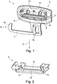
- Figures 1 and 4th show a lock tongue 1 with a tongue body 3 which extends in an insertion direction 2 and which comprises a plate and an extrusion coating.
- a belt slot 4 running transversely to the insertion direction 2 is formed in the tongue body 3.
- In the tongue body 3 is a in the Figure 2 individually illustrated blocking element 5 is movably arranged.
- the blocking element 5 comprises a first part 12 and a second part 13, which are spaced apart from one another by a recess 11.
- the belt strap, not shown, is passed through the recess 11.
- the blocking element 5 also comprises laterally projecting stop elements 15, wherein in the encapsulation of the tongue body 3 counter-stop surfaces are formed, with which the stop elements 15 of the blocking element come into contact in the loading position.
- the blocking element 5 is rotatably mounted in the tongue body 3 by means of a torsion bar.
- the force acting on the second part 13 from the belt strap ensures that the blocking element 5 is pivoted, whereby the first part 12 of the blocking element 5, which forms a narrowing section, along a contact surface 14 of the lock body 3 is moved, whereby a scissors-like chicane for the belt strap is formed between the contact surface 14 and the first part 12 of the blocking element.
- a scissors-like chicane for the belt strap is formed between the contact surface 14 and the first part 12 of the blocking element.
- FIG. 3 On the tongue body 3 is an in Figure 3 Cover 6 shown in detail can be attached.
- the cover 6 is U-shaped and has a section 7 and two legs 10 protruding therefrom.
- the cover 6 On a side facing the tongue body 3, the cover 6 has projections 8 which can be introduced into corresponding recesses 9 on the tongue body 3 in order to secure the cover 6 in a non-positive manner.
- the subsection 7 directly adjoins the belt slot 4, so that the first part 12 of the blocking element 5 is covered by the subsection 7.
- the legs 10 of the cover 6 extend laterally along the belt slot 4 and cover the stop elements 15.
- the legs 10 extend with their ends to an upper side of the lock tongue 1, so that the surface of the ends are directed upwards.
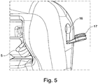
- an opening 16 for inserting a torsion bar is formed in the extrusion coating of the tongue body 3.
- the opening 16 can be closed by a closure 17 which is integrally molded onto the extrusion coating of the tongue body 3.
- an opening 16 in the encapsulation of the lock tongue 1 is closed by first forming a collar around the opening 16, which is pressed into the opening 16 by means of a stamp for closing.
- the opening 16 to be closed by a plug which is introduced into the opening 16.
- a piece of a wire made of a suitable material could be cut off and introduced into the opening.
Landscapes
- Engineering & Computer Science (AREA)
- Mechanical Engineering (AREA)
- Automotive Seat Belt Assembly (AREA)
Description
- Die vorliegende Erfindung betrifft eine Schlosszunge mit einem sich in einer Einsteckrichtung erstreckenden Zungenkörper, in dem quer zur Einsteckrichtung ein Gurtschlitz zur Durchführung eines Gurtbandes ausgebildet ist, und einem beweglich in dem Zungenkörper angeordneten Blockierelement, wobei das Gurtband in einer unbelasteten Durchlaufstellung des Blockierelements durch den Gurtschlitz beweglich ist und in einer durch eine in das Gurtband eingeleitete Zugkraft herbeigeführten Belastungsstellung mittels des Blockierelements in seiner Beweglichkeit zumindest gehemmt ist, wobei das Gurtband im angeschnallten Zustand schlaufenförmig von der Zunge umgelenkt ist.
- Eine Schlosszunge mit den eingangs genannten Merkmalen ist aus
DE 198 22 473 A1 bekannt, bei der ein als Klemmelement ausgebildetes Blockierelement drehbar um eine Achse angeordnet ist. Überschreitet die Gurtkraft einen vorbestimmten Wert, schwenkt das Klemmelement um seine Achse und klemmt das Gurtband mit einer Klemmkante gegen einen Klemmbacken des Zungenkörpers. Es hat sich nun herausgestellt, dass die bei einem Unfall auftretenden Kräfte so groß sind, dass die Schlosszunge verformt wird, wobei die Klemmkante des Klemmelements das Gurtband nicht sicher gegen den Klemmbacken klemmt. - Aus
EP 2 377 417 B1 ist daher eine Schlosszunge bekannt, bei der das Umlenkelement aus der Durchlaufstellung in die Belastungsstellung entlang einer Anlagenfläche des Zungenkörpers bewegt wird, sodass für das Gurtband eine scherenartige Schikane ausgebildet wird, durch die das Gurtband verläuft und in der das Gurtband mit seinen Seiten flächig in Anlage mit der Anlagefläche des Zungenkörpers beziehungsweise mit dem Verengungsabschnitt des Blockierelements ist. Allerdings baut diese Schlosszunge aufgrund der Lagerung des Blockierelements mit seiner konvexen Außenfläche am Zungenkörper relativ groß und unsymmetrisch. Bei dieser Schlosszunge ist der konvexe Hohlraum, in den die nach oben und zur Vorderseite ausgerichteten Gurtschlitze münden und in dem das Blockierelement angeordnet ist, an der Vorderseite des Zungenkörpers von einer Abdeckung verschlossen. - Eine Schlosszunge mit den Merkmalen des Oberbegriffs des Anspruchs 1 ist aus
DE 10 2014 114 207 A1 bekannt. AusDE 10 2006 033 544 A1 ist zudem eine Schlosszunge bekannt, an dessen metallischer Platine sowohl ein Ende eines Beckengurtes als auch ein Ende eines Schultergurtes unbeweglich befestigt ist, wobei zwei Abdeckelemente die Platine im Bereich der Befestigung der Gurtenden umgeben. - Aufgabe der vorliegenden Erfindung ist es, die mit Bezug zum Stand der Technik geschilderten Probleme zumindest teilweise zu lösen und insbesondere eine Schlosszunge anzugeben, die einen kompakten Gesamteindruck vermittelt.
- Gelöst wird die Aufgabe durch eine Schlosszunge mit den Merkmalen des unabhängigen Anspruchs. Vorteilhafte Weiterbildungen der Schlosszunge sind in den abhängigen Ansprüchen und in der Beschreibung angegeben, wobei einzelne Merkmale der vorteilhaften Weiterbildungen in technisch sinnvoller Weise beliebig miteinander kombinierbar sind.
- Gelöst wird die Aufgabe durch eine Schlosszunge mit den eingangs genannten Merkmalen, bei der auf zumindest einer Seite des Zungenkörpers eine Abdeckung vorgesehen ist und die Abdeckung zumindest mit einem Teilabschnitt unterhalb des Gurtschlitzes angeordnet ist, wobei der unterhalb des Gurtschlitzes angeordnete Teilabschnitt der Abdeckung unmittelbar an den Gurtschlitz angrenzt und zumindest einen Teil des sich in der Durchlaufstellung befindlichen Blockierelements überdeckt.
- Die Richtungsangaben beziehen sich auf die Einsteckrichtung der Schlosszunge, sodass der in das Gurtschloss einzusteckende Abschnitt der Schlosszunge unten angeordnet ist und der den Gurtschlitz aufweisende Abschnitt oben an der Schlosszunge angeordnet ist. Als Vorderseite wird hierbei die Seite der Schlosszunge aufgefasst, die im nicht angeschnallten Zustand, wenn die Schlosszunge im Bereich der B-Säule angeordnet ist, dem Insassen zugewandt ist. Die Rückseite ist also die in der abgeschnallten Stellung der B-Säule zugewandten Seite.
- Die Erfindung betrifft insbesondere solche Schlosszungen, bei der sich der Gurtschlitz von der Rückseite zur Vorderseite erstreckt. Die Abdeckung befindet sich also an der Vorderseite oder an der Rückseite unmittelbar unterhalb des Gurtschlitzes, der an einer dieser Seiten mündet. Das Gurtband ist also insbesondere nicht an einer Oberseite aus der Schlosszunge herausgeführt.
- Durch die Anordnung der Abdeckung unterhalb des Gurtschlitzes an der Vorder- oder Rückseite wird bei Schlosszungen, die ein Blockierelement aufweisen, ein kompakter Gesamteindruck vermittelt, wobei ein Abschnitt oder Teil des Blockierelements so hinter der Abdeckung angeordnet ist, dass es für einen Insassen bei normalem Gebrauch insbesondere im abgeschnallten Zustand nicht ersichtlich ist. Insbesondere ist die Abdeckung auf einer im abgeschnallten Zustand dem Insassen zugewandten Vorderseite der Schlosszunge angeordnet. Die Abdeckung kann aber auch auf der Rückseite angeordnet sein oder es kann jeweils eine Abdeckung auf der Vorder- und Rückseite angeordnet sein. Die Abdeckung ermöglicht es zudem, eine für die Montage des Blockierelements auf der Vorder- beziehungsweise Rückseite angeordnete Aussparung nach der Montage einfach zu überdecken. Die Abdeckung begrenzt also an der Vorder- oder Rückseite unmittelbar den Gurtschlitz. Es kann auch vorgesehen sein, dass die Abdeckung sich zumindest teilweise von der Vorderseite beziehungsweise Rückseite in den Zungenkörper zumindest teilweise hinein und damit zumindest teilweise durch den Zungenkörper parallel zum Gurtschlitz erstreckt.
- In einer Ausführungsform weist das Blockierelement eine Aussparung auf, durch die das Gurtband insbesondere innerhalb des Gurtschlitzes durchführbar ist, sodass ein erster Teil des Blockierelements außerhalb der zumindest im angeschnallten Zustand gebildeten Schlaufe des Gurtbandes und ein zweiter, von dem ersten Teil durch die Aussparung beabstandeter Teil des Blockierelements innerhalb der zumindest im angeschnallten Zustand gebildeten Schlaufe des Gurtbandes angeordnet ist, wobei die Abdeckung den ersten Teil überdeckt. Der erste Teil des Blockierelements ist somit unterhalb der Gurtschlaufe angeordnet.
- Der erste Teil des Blockierelements kann insbesondere bevorzugt mit seinem ersten Teil einen Verengungsabschnitt ausbilden, der von der Durchlaufstellung in die Belastungsstellung entlang einer Anlagefläche des Zungenkörpers bewegbar ist, sodass das Gurtband in der Belastungsstellung mit einem Gurtbandabschnitt sowohl mit der Anlagefläche des Zungenkörpers als auch mit dem Verengungsabschnitt des Blockierelements flächig in Anlage ist, wobei der Verengungsabschnitt zumindest in der Durchlaufstellung des Blockierelements von der Abdeckung überdeckt ist. Der Verengungsabschnitt und die Anlageflächen bilden in der Belastungsstellung also eine scherenartige Schikane aus, die das Gurtband in seiner Bewegung hemmt. In diesem Zusammenhang ist besonders bevorzugt, wenn zumindest in der Belastungsstellung der Zungenkörper mit einem die Anlagefläche aufweisenden Bereich durch zumindest einen Abschnitt, insbesondere durch die oben angesprochene Aussparung des Blockierelements hindurchgreift. In der Belastungsstellung ist also der die Anlagefläche aufweisende Abschnitt des Zungenkörpers in der Aussparung angeordnet, durch welche auch das Gurtband hindurchgeführt wird. Zwischen der Anlagefläche und dem entsprechenden Abschnitt des Zungenkörpers wird die scherenartige Schikane ausgebildet.
- Für eine einfache Montage ist es bevorzugt, dass die Abdeckung kraftschlüssig an dem Zungenkörper festgelegt ist, wobei die Abdeckung insbesondere mittels unterhalb des Gurtschlitzes angeordneten und mit entsprechenden Ausnehmungen wechselwirkenden Vorsprüngen kraftschlüssig festgelegt ist. Die Vorsprünge können also an der Abdeckung ausgebildet sein, während die komplementären Ausnehmungen am Zungenkörper ausgebildet sind oder umgekehrt.
- In einer weiteren Ausführungsform kann vorgesehen sein, dass die Abdeckung U-förmig ausgebildet ist und die Schenkel an den Gurtschlitz seitlich angrenzen, wobei der die Schenkel verbindende Teilabschnitt der Abdeckung unterhalb des Gurtschlosses angeordnet ist. Die Schenkel der U-förmigen Abdeckung sind also seitlich des Gurtschlitzes angeordnet und überdecken Abschnitte des Blockierelements. Insbesondere können sich die Schenkel der U-förmigen Abdeckung mit ihren Enden bis zu einem nach oben gerichteten Oberflächenabschnitt des Zungenkörpers erstrecken, wobei auch die Oberflächen der Enden der Schenkel nach oben gerichtet sind. Somit können ansonsten auch von oben sichtbare Elemente des Blockierelements von den Schenkeln abgedeckt werden. An den Schenkeln können Vorsprünge zur zusätzlichen kraftschlüssigen Festlegung der Abdeckung an dem Zungenkörper vorgesehen sein.
- Die Abdeckung U-förmig auszuführen, kann insbesondere dann sinnvoll sein, wenn an dem Blockierelement nach außen auskragende Anschlagselemente ausgebildet sind, die in der Belastungsstellung in Anlage mit Gegenanschlagsflächen an dem Zungenkörper sind, wobei die Gegenanschlagsflächen seitlich von dem Gurtschlitz angeordnet sind. In diesem Zusammenhang kann vorgesehen sein, dass jeweils eine Kappe auf die Anschlagselemente des Blockierelements aufgebracht ist, wobei die Kappe einen dunklen Farbton insbesondere entsprechend dem Farbton der Umspritzung der Schlosszunge aufweist, sodass die Anschlagselemente für den Insassen nicht einfach zu erkennen sind.
- Insbesondere auch unabhängig von der zuvor beschriebenen Lösung kann auch durch Lackierung des Blockierelements in einem dunklen Farbton erreicht werden, dass das Blockierelement für Insassen insbesondere in der abgeschnallten Stellung nicht ohne weiteres erkennbar ist. Insbesondere können auch nur Teilbereiche des Blockierelements lackiert sein.
- Es kann auch vorgesehen sein, dass das Gurtband durch die Abdeckung hindurchführbar ist, sodass die Abdeckung den Gurtschlitz auf der Seite des Zungenkörpers umschließt und der Gurtschlitz von der Abdeckung vollumfänglich auf der entsprechenden Seite des Zungenkörpers begrenzt ist.
- Der Zungenkörper ist durch eine Platine aus Metall und eine die Platine zumindest teilweise umgebende Umspritzung aus Kunststoff gebildet.
- Die Erfindung sowie das technische Umfeld werden nachfolgend anhand der Figuren beispielhaft erläutert. Es zeigen schematisch
- Figur 1:
- eine teilweise Explosionsansicht einer Schlosszunge,
- Figur 2:
- ein Blockierelement der Schlosszunge,
- Figur 3:
- eine Rückansicht auf eine Abdeckung der Schlosszunge,
- Figur 4:
- eine Perspektivansicht der Schlosszunge mit montierter Abdeckung und
- Figur 5:
- eine Detailansicht einer weiteren Ausführungsform einer Schlosszunge.
-
Figuren 1 und4 zeigen eine Schlosszunge 1 mit einem sich in eine Einsteckrichtung 2 erstreckenden Zungenkörper 3, welcher eine Platine und eine Umspritzung umfasst. In dem Zungenkörper 3 ist eine quer zur Einsteckrichtung 2 verlaufender Gurtschlitz 4 ausgebildet. In dem Zungenkörper 3 ist ein in derFigur 2 einzeln dargestelltes Blockierelement 5 beweglich angeordnet. - Das Blockierelement 5 umfasst einen ersten Teil 12 und einen zweiten Teil 13, die durch eine Aussparung 11 voneinander beabstandet sind. Durch die Aussparung 11 ist das nicht dargestellte Gurtband hindurchgeführt. Das Blockierelement 5 umfasst zudem seitlich auskragende Anschlagselemente 15, wobei in der Umspritzung des Zungenkörpers 3 Gegenanschlagsflächen ausgebildet sind, mit denen die Anschlagselemente 15 des Blockierelements in der Belastungsstellung in Anlage kommen. Das Blockierelement 5 ist mittels eines Torsionsstabes drehbar in dem Zungenkörper 3 gelagert. Wird im angeschnallten Zustand eine Zugkraft in das Gurtband eingeleitet, so sorgt die von dem Gurtband auf den zweiten Teil 13 wirkende Kraft dafür, dass das Blockierelement 5 verschwenkt wird, wodurch der einen Verengungsabschnitt ausbildende erste Teil 12 des Blockierelements 5 entlang einer Anlagefläche 14 des Schlosskörpers 3 bewegt wird, wodurch eine scherenartige Schikane für das Gurtband zwischen der Anlagefläche 14 und dem ersten Teil 12 des Blockierelements ausgebildet wird. Durch diese Schikane wird die Bewegung des Gurtbandes zumindest gehemmt, wenn nicht sogar vollständig unterbunden.
- An den Zungenkörper 3 ist eine in
Figur 3 im Detail dargestellte Abdeckung 6 anbringbar. Die Abdeckung 6 ist U-förmig ausgestaltet und weist einen Teilabschnitt 7 und zwei davon abstehende Schenkel 10 auf. Auf einer dem Zungenkörper 3 zugewandten Seite weist die Abdeckung 6 Vorsprünge 8 auf, die zur kraftschlüssigen Festlegung der Abdeckung 6 in entsprechende Ausnehmungen 9 am Zungenkörper 3 einbringbar sind. Wie ausFigur 4 ersichtlich ist, grenzt der Teilabschnitt 7 unmittelbar an den Gurtschlitz 4 an, sodass durch den Teilabschnitt 7 der erste Teil 12 des Blockierelements 5 überdeckt ist. Die Schenkel 10 der Abdeckung 6 erstrecken sich seitlich entlang des Gurtschlitzes 4 und überdecken die Anschlagselemente 15. Die Schenkel 10 erstrecken sich mit ihren Enden zu einer Oberseite der Schlosszunge 1, sodass die Oberfläche der Enden nach oben gerichtet sind. - Aus
Figur 5 ist zu erkennen, dass in der Umspritzung des Zungenkörpers 3 eine Öffnung 16 zum Einführen eines Torsionsstabes ausgebildet ist. Die Öffnung 16 kann durch einen einteilig an die Umspritzung des Zungenkörpers 3 angespritzten Verschluss 17 verschlossen werden. Es wäre auch vorstellbar, dass eine Öffnung 16 in der Umspritzung der Schlosszunge 1 dadurch verschlossen wird, dass zunächst ein Kragen um die Öffnung 16 herum ausgebildet wird, welcher mittels eines Stempels zum Verschließen in die Öffnung 16 gedrückt wird. Es wäre auch vorstellbar, dass die Öffnung 16 durch einen Stopfen verschlossen wird, der in die Öffnung 16 eingebracht wird. Hierzu könnte beispielsweise ein Stück von einem Draht aus einem entsprechenden Material abgetrennt werden und in die Öffnung eingebracht werden. -
- 1
- Schlosszunge
- 2
- Einsteckrichtung
- 3
- Zungenkörper
- 4
- Gurtschlitz
- 5
- Blockierelement
- 6
- Abdeckung
- 7
- Teilabschnitt
- 8
- Vorsprung
- 9
- Ausnehmung
- 10
- Schenkel
- 11
- Aussparung
- 12
- erster Teil
- 13
- zweiter Teil
- 14
- Anlagefläche
- 15
- Anschlagselement
- 16
- Öffnung
- 17
- Verschluss
Claims (10)
- Schlosszunge (1) mit einem sich in eine Einsteckrichtung (2) erstreckenden Zungenkörper (3), wobei der Zungenkörper (3) durch eine Platine aus Metall und eine die Platine zumindest teilweise umgebende Umspritzung aus Kunststoff gebildet ist und wobei in dem Zungenkörper (3) quer zur Einsteckrichtung (2) ein Gurtschlitz (4) zur Durchführung eines Gurtbandes ausgebildet ist, und mit einem beweglich in dem Zungenkörper (3) angeordneten Blockierelement (5), wobei das Gurtband in einer unbelasteten Durchlaufstellung des Blockierelements (5) durch den Gurtschlitz (4) beweglich ist und in einer durch eine in das Gurtband eingeleitete Zugkraft herbeigeführten Belastungsstellung mittels des Blockierelements (5) in seiner Beweglichkeit zumindest gehemmt ist, wobei das Gurtband im angeschnallten Zustand schlaufenförmig von der Schlosszunge (1) umgelenkt ist, dadurch gekennzeichnet, dass auf zumindest einer Seite des Zungenkörpers (3) eine Abdeckung (6) vorgesehen ist und die Abdeckung (6) zumindest mit einem Teilabschnitt (7) unterhalb des Gurtschlitzes (4) angeordnet ist, wobei der unterhalb des Gurtschlitzes (4) angeordnete Teilabschnitt (7) der Abdeckung (6) unmittelbar an den Gurtschlitz (4) angrenzt und zumindest einen Teil des sich in der Durchlaufstellung befindlichen Blockierelements (5) überdeckt.
- Schlosszunge (1) nach Anspruch 1, wobei die Abdeckung (6) kraftschlüssig an dem Zungenkörper (2) festgelegt ist.
- Schlosszunge (1) nach Anspruch 2, wobei die Abdeckung (6) mittels unterhalb des Gurtschlitzes (4) angeordneten und mit entsprechenden Ausnehmungen (9) wechselwirkenden Vorsprüngen (8) kraftschlüssig festgelegt ist.
- Schlosszunge (1) nach einem der vorhergehenden Ansprüche, wobei die Abdeckung U-förmig ausgebildet ist und die Schenkel (10) an den Gurtschlitz (4) seitlich angrenzen.
- Schlosszunge (1) nach Anspruch 4, wobei die Schenkel (10) seitlich des Gurtschlitzes (4) angeordnete Abschnitte des Blockierelements (5) überdecken.
- Schlosszunge (1) nach Anspruch 4 oder 5, wobei die Schenkel (10) sich bis zu einem nach oben gerichteten Oberflächenabschnitt des Zungenkörpers (2) erstrecken und die Oberflächen ihrer Enden nach oben gerichtet sind.
- Schlosszunge (1) nach einem der Ansprüche 1 bis 3, wobei die Abdeckung (6) den Gurtschlitz (4) auf der Seite des Zungenkörpers (3) umschließt, so dass der Gurtschlitz (4) auf der Seite des Zungenkörpers (3) von der Abdeckung (6) vollumfänglich begrenzt ist.
- Schlosszunge (1) nach einem der vorhergehenden Ansprüche, wobei das Blockierelement (5) eine Aussparung (11) aufweist, durch die das Gurtband durchführbar ist, so dass ein erster Teil (12) des Blockierelements (5) außerhalb der zumindest im angeschnallten Zustand gebildeten Schlaufe des Gurtbandes und ein zweiter, von dem ersten Teil durch die Aussparung (11) beabstandeter Teil (13) des Blockierelements (5) innerhalb der zumindest im angeschnallten Zustand gebildeten Schlaufe des Gurtbandes angeordnet ist, wobei die Abdeckung (6) den ersten Teil (12) überdeckt.
- Schlosszunge (1) nach einem der vorhergehenden Ansprüche, wobei das Blockierelement (5) von der Durchlaufstellung in die Belastungsstellung mit einem Verengungsabschnitt entlang einer Anlagefläche (14) des Zungenkörpers (3) bewegbar ist, so dass das Gurtband in der Belastungsstellung mit einem Gurtbandabschnitt sowohl mit der Anlagefläche (14) des Zungenkörpers (3) als auch mit dem Verengungsabschnitt des Blockierelements (5) flächig in Anlage ist, wobei der Verengungsabschnitt zumindest in der Durchlaufstellung des Blockierelements (5) von der Abdeckung (6) überdeckt ist.
- Schlosszunge (1) nach Anspruch 9, wobei zumindest in der Belastungsstellung der Zungenkörper (3) mit einem die Anlagefläche (14) aufweisenden Bereich durch zumindest einen Abschnitt des Blockierelements (5) hindurchgreift.
Applications Claiming Priority (2)
| Application Number | Priority Date | Filing Date | Title |
|---|---|---|---|
| DE102017121613.8A DE102017121613A1 (de) | 2017-09-18 | 2017-09-18 | Schlosszunge mit Abdeckung |
| PCT/EP2018/075024 WO2019053245A1 (de) | 2017-09-18 | 2018-09-17 | Schlosszunge mit abdeckung |
Publications (2)
| Publication Number | Publication Date |
|---|---|
| EP3684656A1 EP3684656A1 (de) | 2020-07-29 |
| EP3684656B1 true EP3684656B1 (de) | 2021-07-07 |
Family
ID=63683855
Family Applications (1)
| Application Number | Title | Priority Date | Filing Date |
|---|---|---|---|
| EP18778398.0A Active EP3684656B1 (de) | 2017-09-18 | 2018-09-17 | Schlosszunge mit abdeckung |
Country Status (5)
| Country | Link |
|---|---|
| US (1) | US11142160B2 (de) |
| EP (1) | EP3684656B1 (de) |
| CN (1) | CN111094080B (de) |
| DE (1) | DE102017121613A1 (de) |
| WO (1) | WO2019053245A1 (de) |
Families Citing this family (2)
| Publication number | Priority date | Publication date | Assignee | Title |
|---|---|---|---|---|
| DE102019109697A1 (de) | 2019-04-12 | 2020-10-15 | Trw Automotive Gmbh | Steckzunge für einen Sicherheitsgurt |
| USD1048929S1 (en) * | 2020-05-20 | 2024-10-29 | Australian Performance Vehicles Pty Ltd | Tongue |
Family Cites Families (31)
| Publication number | Priority date | Publication date | Assignee | Title |
|---|---|---|---|---|
| US4588207A (en) * | 1982-11-08 | 1986-05-13 | Gateway Industries, Inc. | Free-falling, self-locking adjustable tip assembly |
| US4480854A (en) * | 1982-11-08 | 1984-11-06 | Gateway Industries, Inc. | Free-falling, self-locking adjustable tip assembly |
| US4617705A (en) * | 1985-08-05 | 1986-10-21 | Indiana Mills & Manufacturing, Inc. | Child belt buckle |
| CN2054990U (zh) * | 1989-02-11 | 1990-03-28 | 杨浩 | E型扣环 |
| US5100176A (en) * | 1991-05-10 | 1992-03-31 | Trw Vehicle Safety Systems Inc. | Tongue assembly |
| JPH05154008A (ja) * | 1991-12-06 | 1993-06-22 | Takata Kk | シートベルト装置のトングアセンブリ |
| JPH0626518U (ja) * | 1992-09-09 | 1994-04-12 | 吉田工業株式会社 | バックル |
| CN2153251Y (zh) * | 1993-03-31 | 1994-01-19 | 陈国仁 | 新型无孔式皮带扣 |
| US6089605A (en) * | 1996-10-07 | 2000-07-18 | Inova Gmbh Technische Entwicklungen | Device for tightening a seat belt in a motor vehicle |
| US5870816A (en) | 1997-05-19 | 1999-02-16 | Trw Vehicle Safety Systems Inc. | Method of assembling a tongue assembly for use with a seat belt system |
| US5806148A (en) * | 1997-05-19 | 1998-09-15 | Trw Vehicle Safety Systems Inc. | Tongue assembly |
| KR100435275B1 (ko) * | 2001-09-18 | 2004-06-11 | 기아자동차주식회사 | 자동차용 안전벨트의 높이 조절장치. |
| US6581968B1 (en) * | 2001-10-05 | 2003-06-24 | Simula, Inc. | Safety belt tension transfer system |
| CN2706038Y (zh) * | 2004-04-07 | 2005-06-29 | 西南交通大学 | 摩擦自紧可调的扣锁装置 |
| JP5057550B2 (ja) * | 2005-08-19 | 2012-10-24 | タカタ株式会社 | シートベルト装置 |
| US7716795B2 (en) * | 2005-09-08 | 2010-05-18 | Tk Holdings Inc. | Anti-rattle tongue plate assembly |
| DE102006033544B4 (de) * | 2006-07-20 | 2008-05-08 | Autoliv Development Ab | Sicherheitsgurt-System für ein Kraftfahrzeug und Gurtzunge für ein Sicherheitsgurtsystem |
| US7871132B2 (en) * | 2007-09-18 | 2011-01-18 | Tk Holdings Inc. | Dynamic cinching latch plate |
| CN201200014Y (zh) * | 2008-03-21 | 2009-03-04 | 力顿钮扣配件(深圳)有限公司 | 安全扣具 |
| EP2377417B1 (de) | 2010-04-15 | 2013-01-02 | Volvo Car Corporation | Gurtzunge für einen Sicherheitsgurt |
| FR2962011B1 (fr) * | 2010-07-02 | 2013-07-19 | Zedel | Boucle de fixation perfectionnee a double verrouillage. |
| US9409537B2 (en) * | 2010-09-20 | 2016-08-09 | Trw Vehicle Safety Systems, Inc. | Seat belt system |
| KR101235112B1 (ko) | 2011-02-01 | 2013-02-20 | 주식회사 삼송 | 벨트 락킹텅 및 이를 구비한 시트벨트 |
| JP5943512B2 (ja) * | 2012-07-18 | 2016-07-05 | タカタ株式会社 | タングおよびこれを用いたシートベルト装置 |
| EP2901882B1 (de) * | 2014-01-30 | 2017-05-03 | Autoliv Development AB | Blockierbare Gurtzunge für einen Dreipunkt-Sicherheitsgurt |
| DE102014204199B4 (de) * | 2014-03-07 | 2019-03-07 | Autoliv Development Ab | Schalter für ein Gurtschloss einer Sicherheitsgurteinrichtung |
| DE102014007125A1 (de) * | 2014-05-16 | 2015-11-19 | Trw Automotive Gmbh | Steckzunge und Verfahren zur Herstellung einer Steckzunge |
| DE102014114207B4 (de) * | 2014-09-30 | 2016-11-17 | Autoliv Development Ab | Schlosszunge mit einem einen Führungsabschnitt aufweisenden Klemmelement |
| CN204245329U (zh) * | 2014-09-30 | 2015-04-08 | 浙江吉利控股集团有限公司 | 一种汽车安全带结构 |
| CN205611937U (zh) * | 2016-04-08 | 2016-10-05 | 延锋百利得(上海)汽车安全系统有限公司 | 安全带锁舌 |
| US10611334B2 (en) * | 2017-02-07 | 2020-04-07 | Shield Restraint Systems, Inc. | Web adjuster |
-
2017
- 2017-09-18 DE DE102017121613.8A patent/DE102017121613A1/de active Pending
-
2018
- 2018-09-17 US US16/648,260 patent/US11142160B2/en active Active
- 2018-09-17 WO PCT/EP2018/075024 patent/WO2019053245A1/de not_active Ceased
- 2018-09-17 EP EP18778398.0A patent/EP3684656B1/de active Active
- 2018-09-17 CN CN201880057972.0A patent/CN111094080B/zh active Active
Also Published As
| Publication number | Publication date |
|---|---|
| EP3684656A1 (de) | 2020-07-29 |
| CN111094080A (zh) | 2020-05-01 |
| WO2019053245A1 (de) | 2019-03-21 |
| US20200238947A1 (en) | 2020-07-30 |
| US11142160B2 (en) | 2021-10-12 |
| DE102017121613A1 (de) | 2019-03-21 |
| CN111094080B (zh) | 2022-05-13 |
Similar Documents
| Publication | Publication Date | Title |
|---|---|---|
| EP2419290B1 (de) | Fahrzeugrolloanordnung, baugruppe mit einer fahrzeugrolloanordnung, und dachanordnung | |
| DE602004003824T2 (de) | Verschlusseinrichtung für sicherheitsgurte insbesondere für sicherheitssitze für kinder in kraftfahrzeugen | |
| DE29822649U1 (de) | Schaumteil aus Polyurethan o.dgl., insbesondere zur Verwendung als Polsterelement bei der Herstellung von Fahrzeugsitzen | |
| EP3325315A1 (de) | Befestiger zum lösbaren verbinden eines paneels an einer struktur, abdeckpaneel für ein airbag und fahrzeug mit einer struktur und einem airbag | |
| EP1948458A1 (de) | Windabweiser für ein kraftfahrzeug | |
| DE2057043A1 (de) | Kleinstschnalle | |
| DE1858787U (de) | Schnalle fuer sicherheitsgurte od. dgl. | |
| DE20102416U1 (de) | Sicherheitsgurtschloss | |
| EP3684656B1 (de) | Schlosszunge mit abdeckung | |
| DE3151019C2 (de) | Vorrichtung zum Befestigen des oberen Umlenkbeschlages für einen Dreipunktsicherheitsgurt an der Karosserie eines Kraftfahrzeuges | |
| EP3191348B1 (de) | Höhenverstelleinrichtung | |
| DE3112458C2 (de) | Stufenweise höhenverstellbare Sicherheitsgurtumlenkung in Fahrzeugen, insbesondere Kraftfahrzeugen | |
| DE10147621B4 (de) | Befestigungsanordnung für einen seitlichen Endbereich einer Front- oder Heckschürze eines Fahrzeugs | |
| EP1371531B1 (de) | Sicherheitsgurteinrichtung | |
| DE60008788T2 (de) | Verriegelungsplatte mit einer vorrichtung zur verhinderung der verdrehung des gurtes | |
| DE10210781B4 (de) | Befestigungsmittel für einen Sicherheitsgurt | |
| EP1487688A1 (de) | Aus kunststoff bestehender kotflügel eines kraftfahrzeugs und befestigungsvorrichtung desselben | |
| DE8128937U1 (de) | Umlenkbeschlag fuer einen sicherheitsgurt | |
| DE3243643C2 (de) | ||
| EP3867108B1 (de) | Gurtschlossanordnung für ein fahrzeug, ummantelung und verfahren zur ummantelung einer gurtschlossvorrichtung der gurtschlossanordnung | |
| EP1658207B1 (de) | Umlenkelement für sicherheitsgurte mit einstückigem verkleidungsteil | |
| DE3314588C2 (de) | ||
| DE3043475C2 (de) | Passives Dreipunkt-Sicherheitsgurtsystem für den Insassen eines Kraftfahrzeuges | |
| DE10216792C1 (de) | Schloßzunge mit integrierter Umlenkeinrichtung | |
| DE69012716T2 (de) | Schnappverschluss. |
Legal Events
| Date | Code | Title | Description |
|---|---|---|---|
| STAA | Information on the status of an ep patent application or granted ep patent |
Free format text: STATUS: UNKNOWN |
|
| STAA | Information on the status of an ep patent application or granted ep patent |
Free format text: STATUS: THE INTERNATIONAL PUBLICATION HAS BEEN MADE |
|
| PUAI | Public reference made under article 153(3) epc to a published international application that has entered the european phase |
Free format text: ORIGINAL CODE: 0009012 |
|
| STAA | Information on the status of an ep patent application or granted ep patent |
Free format text: STATUS: REQUEST FOR EXAMINATION WAS MADE |
|
| 17P | Request for examination filed |
Effective date: 20200331 |
|
| AK | Designated contracting states |
Kind code of ref document: A1 Designated state(s): AL AT BE BG CH CY CZ DE DK EE ES FI FR GB GR HR HU IE IS IT LI LT LU LV MC MK MT NL NO PL PT RO RS SE SI SK SM TR |
|
| AX | Request for extension of the european patent |
Extension state: BA ME |
|
| RIN1 | Information on inventor provided before grant (corrected) |
Inventor name: BERG, ROBERT Inventor name: HERMANN, MICHEL |
|
| DAV | Request for validation of the european patent (deleted) | ||
| DAX | Request for extension of the european patent (deleted) | ||
| GRAP | Despatch of communication of intention to grant a patent |
Free format text: ORIGINAL CODE: EPIDOSNIGR1 |
|
| STAA | Information on the status of an ep patent application or granted ep patent |
Free format text: STATUS: GRANT OF PATENT IS INTENDED |
|
| INTG | Intention to grant announced |
Effective date: 20210406 |
|
| RIN1 | Information on inventor provided before grant (corrected) |
Inventor name: HERMANN, MICHEL Inventor name: BERG, ROBERT |
|
| GRAS | Grant fee paid |
Free format text: ORIGINAL CODE: EPIDOSNIGR3 |
|
| GRAA | (expected) grant |
Free format text: ORIGINAL CODE: 0009210 |
|
| STAA | Information on the status of an ep patent application or granted ep patent |
Free format text: STATUS: THE PATENT HAS BEEN GRANTED |
|
| AK | Designated contracting states |
Kind code of ref document: B1 Designated state(s): AL AT BE BG CH CY CZ DE DK EE ES FI FR GB GR HR HU IE IS IT LI LT LU LV MC MK MT NL NO PL PT RO RS SE SI SK SM TR |
|
| REG | Reference to a national code |
Ref country code: GB Ref legal event code: FG4D Free format text: NOT ENGLISH |
|
| REG | Reference to a national code |
Ref country code: AT Ref legal event code: REF Ref document number: 1408274 Country of ref document: AT Kind code of ref document: T Effective date: 20210715 |
|
| REG | Reference to a national code |
Ref country code: DE Ref legal event code: R096 Ref document number: 502018006085 Country of ref document: DE |
|
| REG | Reference to a national code |
Ref country code: IE Ref legal event code: FG4D Free format text: LANGUAGE OF EP DOCUMENT: GERMAN |
|
| REG | Reference to a national code |
Ref country code: LT Ref legal event code: MG9D |
|
| REG | Reference to a national code |
Ref country code: NL Ref legal event code: MP Effective date: 20210707 |
|
| PG25 | Lapsed in a contracting state [announced via postgrant information from national office to epo] |
Ref country code: RS Free format text: LAPSE BECAUSE OF FAILURE TO SUBMIT A TRANSLATION OF THE DESCRIPTION OR TO PAY THE FEE WITHIN THE PRESCRIBED TIME-LIMIT Effective date: 20210707 Ref country code: SE Free format text: LAPSE BECAUSE OF FAILURE TO SUBMIT A TRANSLATION OF THE DESCRIPTION OR TO PAY THE FEE WITHIN THE PRESCRIBED TIME-LIMIT Effective date: 20210707 Ref country code: HR Free format text: LAPSE BECAUSE OF FAILURE TO SUBMIT A TRANSLATION OF THE DESCRIPTION OR TO PAY THE FEE WITHIN THE PRESCRIBED TIME-LIMIT Effective date: 20210707 Ref country code: ES Free format text: LAPSE BECAUSE OF FAILURE TO SUBMIT A TRANSLATION OF THE DESCRIPTION OR TO PAY THE FEE WITHIN THE PRESCRIBED TIME-LIMIT Effective date: 20210707 Ref country code: FI Free format text: LAPSE BECAUSE OF FAILURE TO SUBMIT A TRANSLATION OF THE DESCRIPTION OR TO PAY THE FEE WITHIN THE PRESCRIBED TIME-LIMIT Effective date: 20210707 Ref country code: LT Free format text: LAPSE BECAUSE OF FAILURE TO SUBMIT A TRANSLATION OF THE DESCRIPTION OR TO PAY THE FEE WITHIN THE PRESCRIBED TIME-LIMIT Effective date: 20210707 Ref country code: BG Free format text: LAPSE BECAUSE OF FAILURE TO SUBMIT A TRANSLATION OF THE DESCRIPTION OR TO PAY THE FEE WITHIN THE PRESCRIBED TIME-LIMIT Effective date: 20211007 Ref country code: NO Free format text: LAPSE BECAUSE OF FAILURE TO SUBMIT A TRANSLATION OF THE DESCRIPTION OR TO PAY THE FEE WITHIN THE PRESCRIBED TIME-LIMIT Effective date: 20211007 Ref country code: PT Free format text: LAPSE BECAUSE OF FAILURE TO SUBMIT A TRANSLATION OF THE DESCRIPTION OR TO PAY THE FEE WITHIN THE PRESCRIBED TIME-LIMIT Effective date: 20211108 Ref country code: NL Free format text: LAPSE BECAUSE OF FAILURE TO SUBMIT A TRANSLATION OF THE DESCRIPTION OR TO PAY THE FEE WITHIN THE PRESCRIBED TIME-LIMIT Effective date: 20210707 |
|
| PG25 | Lapsed in a contracting state [announced via postgrant information from national office to epo] |
Ref country code: PL Free format text: LAPSE BECAUSE OF FAILURE TO SUBMIT A TRANSLATION OF THE DESCRIPTION OR TO PAY THE FEE WITHIN THE PRESCRIBED TIME-LIMIT Effective date: 20210707 Ref country code: LV Free format text: LAPSE BECAUSE OF FAILURE TO SUBMIT A TRANSLATION OF THE DESCRIPTION OR TO PAY THE FEE WITHIN THE PRESCRIBED TIME-LIMIT Effective date: 20210707 Ref country code: GR Free format text: LAPSE BECAUSE OF FAILURE TO SUBMIT A TRANSLATION OF THE DESCRIPTION OR TO PAY THE FEE WITHIN THE PRESCRIBED TIME-LIMIT Effective date: 20211008 |
|
| REG | Reference to a national code |
Ref country code: DE Ref legal event code: R097 Ref document number: 502018006085 Country of ref document: DE |
|
| PG25 | Lapsed in a contracting state [announced via postgrant information from national office to epo] |
Ref country code: DK Free format text: LAPSE BECAUSE OF FAILURE TO SUBMIT A TRANSLATION OF THE DESCRIPTION OR TO PAY THE FEE WITHIN THE PRESCRIBED TIME-LIMIT Effective date: 20210707 |
|
| REG | Reference to a national code |
Ref country code: CH Ref legal event code: PL |
|
| PLBE | No opposition filed within time limit |
Free format text: ORIGINAL CODE: 0009261 |
|
| STAA | Information on the status of an ep patent application or granted ep patent |
Free format text: STATUS: NO OPPOSITION FILED WITHIN TIME LIMIT |
|
| REG | Reference to a national code |
Ref country code: BE Ref legal event code: MM Effective date: 20210930 |
|
| PG25 | Lapsed in a contracting state [announced via postgrant information from national office to epo] |
Ref country code: SM Free format text: LAPSE BECAUSE OF FAILURE TO SUBMIT A TRANSLATION OF THE DESCRIPTION OR TO PAY THE FEE WITHIN THE PRESCRIBED TIME-LIMIT Effective date: 20210707 Ref country code: SK Free format text: LAPSE BECAUSE OF FAILURE TO SUBMIT A TRANSLATION OF THE DESCRIPTION OR TO PAY THE FEE WITHIN THE PRESCRIBED TIME-LIMIT Effective date: 20210707 Ref country code: RO Free format text: LAPSE BECAUSE OF FAILURE TO SUBMIT A TRANSLATION OF THE DESCRIPTION OR TO PAY THE FEE WITHIN THE PRESCRIBED TIME-LIMIT Effective date: 20210707 Ref country code: MC Free format text: LAPSE BECAUSE OF FAILURE TO SUBMIT A TRANSLATION OF THE DESCRIPTION OR TO PAY THE FEE WITHIN THE PRESCRIBED TIME-LIMIT Effective date: 20210707 Ref country code: EE Free format text: LAPSE BECAUSE OF FAILURE TO SUBMIT A TRANSLATION OF THE DESCRIPTION OR TO PAY THE FEE WITHIN THE PRESCRIBED TIME-LIMIT Effective date: 20210707 Ref country code: CZ Free format text: LAPSE BECAUSE OF FAILURE TO SUBMIT A TRANSLATION OF THE DESCRIPTION OR TO PAY THE FEE WITHIN THE PRESCRIBED TIME-LIMIT Effective date: 20210707 Ref country code: AL Free format text: LAPSE BECAUSE OF FAILURE TO SUBMIT A TRANSLATION OF THE DESCRIPTION OR TO PAY THE FEE WITHIN THE PRESCRIBED TIME-LIMIT Effective date: 20210707 |
|
| 26N | No opposition filed |
Effective date: 20220408 |
|
| PG25 | Lapsed in a contracting state [announced via postgrant information from national office to epo] |
Ref country code: LU Free format text: LAPSE BECAUSE OF NON-PAYMENT OF DUE FEES Effective date: 20210917 Ref country code: IT Free format text: LAPSE BECAUSE OF FAILURE TO SUBMIT A TRANSLATION OF THE DESCRIPTION OR TO PAY THE FEE WITHIN THE PRESCRIBED TIME-LIMIT Effective date: 20210707 Ref country code: IE Free format text: LAPSE BECAUSE OF NON-PAYMENT OF DUE FEES Effective date: 20210917 Ref country code: BE Free format text: LAPSE BECAUSE OF NON-PAYMENT OF DUE FEES Effective date: 20210930 |
|
| PG25 | Lapsed in a contracting state [announced via postgrant information from national office to epo] |
Ref country code: LI Free format text: LAPSE BECAUSE OF NON-PAYMENT OF DUE FEES Effective date: 20210930 Ref country code: CH Free format text: LAPSE BECAUSE OF NON-PAYMENT OF DUE FEES Effective date: 20210930 |
|
| P01 | Opt-out of the competence of the unified patent court (upc) registered |
Effective date: 20230507 |
|
| PG25 | Lapsed in a contracting state [announced via postgrant information from national office to epo] |
Ref country code: CY Free format text: LAPSE BECAUSE OF FAILURE TO SUBMIT A TRANSLATION OF THE DESCRIPTION OR TO PAY THE FEE WITHIN THE PRESCRIBED TIME-LIMIT Effective date: 20210707 |
|
| PG25 | Lapsed in a contracting state [announced via postgrant information from national office to epo] |
Ref country code: HU Free format text: LAPSE BECAUSE OF FAILURE TO SUBMIT A TRANSLATION OF THE DESCRIPTION OR TO PAY THE FEE WITHIN THE PRESCRIBED TIME-LIMIT; INVALID AB INITIO Effective date: 20180917 |
|
| PG25 | Lapsed in a contracting state [announced via postgrant information from national office to epo] |
Ref country code: MK Free format text: LAPSE BECAUSE OF FAILURE TO SUBMIT A TRANSLATION OF THE DESCRIPTION OR TO PAY THE FEE WITHIN THE PRESCRIBED TIME-LIMIT Effective date: 20210707 |
|
| PG25 | Lapsed in a contracting state [announced via postgrant information from national office to epo] |
Ref country code: TR Free format text: LAPSE BECAUSE OF FAILURE TO SUBMIT A TRANSLATION OF THE DESCRIPTION OR TO PAY THE FEE WITHIN THE PRESCRIBED TIME-LIMIT Effective date: 20210707 |
|
| PG25 | Lapsed in a contracting state [announced via postgrant information from national office to epo] |
Ref country code: MT Free format text: LAPSE BECAUSE OF FAILURE TO SUBMIT A TRANSLATION OF THE DESCRIPTION OR TO PAY THE FEE WITHIN THE PRESCRIBED TIME-LIMIT Effective date: 20210707 |
|
| REG | Reference to a national code |
Ref country code: AT Ref legal event code: MM01 Ref document number: 1408274 Country of ref document: AT Kind code of ref document: T Effective date: 20230917 |
|
| PG25 | Lapsed in a contracting state [announced via postgrant information from national office to epo] |
Ref country code: AT Free format text: LAPSE BECAUSE OF NON-PAYMENT OF DUE FEES Effective date: 20230917 |
|
| PG25 | Lapsed in a contracting state [announced via postgrant information from national office to epo] |
Ref country code: AT Free format text: LAPSE BECAUSE OF NON-PAYMENT OF DUE FEES Effective date: 20230917 |
|
| PGFP | Annual fee paid to national office [announced via postgrant information from national office to epo] |
Ref country code: DE Payment date: 20250926 Year of fee payment: 8 |
|
| PGFP | Annual fee paid to national office [announced via postgrant information from national office to epo] |
Ref country code: GB Payment date: 20250923 Year of fee payment: 8 |
|
| PGFP | Annual fee paid to national office [announced via postgrant information from national office to epo] |
Ref country code: FR Payment date: 20250925 Year of fee payment: 8 |
|
| PGFP | Annual fee paid to national office [announced via postgrant information from national office to epo] |
Ref country code: AT Payment date: 20260410 Year of fee payment: 5 |