EP3686164B1 - Form zum formen für eine aus glas hergestellte optische komponente und verfahren zur herstellung einer aus glas hergestellten optischen komponente unter verwendung dieser form - Google Patents
Form zum formen für eine aus glas hergestellte optische komponente und verfahren zur herstellung einer aus glas hergestellten optischen komponente unter verwendung dieser form Download PDFInfo
- Publication number
- EP3686164B1 EP3686164B1 EP19788940.5A EP19788940A EP3686164B1 EP 3686164 B1 EP3686164 B1 EP 3686164B1 EP 19788940 A EP19788940 A EP 19788940A EP 3686164 B1 EP3686164 B1 EP 3686164B1
- Authority
- EP
- European Patent Office
- Prior art keywords
- mold
- molding
- glass
- optical component
- made optical
- Prior art date
- Legal status (The legal status is an assumption and is not a legal conclusion. Google has not performed a legal analysis and makes no representation as to the accuracy of the status listed.)
- Active
Links
Images




Classifications
-
- C—CHEMISTRY; METALLURGY
- C03—GLASS; MINERAL OR SLAG WOOL
- C03B—MANUFACTURE, SHAPING, OR SUPPLEMENTARY PROCESSES
- C03B11/00—Pressing molten glass or performed glass reheated to equivalent low viscosity without blowing
- C03B11/06—Construction of plunger or mould
- C03B11/08—Construction of plunger or mould for making solid articles, e.g. lenses
- C03B11/082—Construction of plunger or mould for making solid articles, e.g. lenses having profiled, patterned or microstructured surfaces
-
- C—CHEMISTRY; METALLURGY
- C03—GLASS; MINERAL OR SLAG WOOL
- C03B—MANUFACTURE, SHAPING, OR SUPPLEMENTARY PROCESSES
- C03B11/00—Pressing molten glass or performed glass reheated to equivalent low viscosity without blowing
- C03B11/06—Construction of plunger or mould
- C03B11/10—Construction of plunger or mould for making hollow or semi-hollow articles
-
- G—PHYSICS
- G02—OPTICS
- G02B—OPTICAL ELEMENTS, SYSTEMS OR APPARATUS
- G02B3/00—Simple or compound lenses
-
- G—PHYSICS
- G02—OPTICS
- G02B—OPTICAL ELEMENTS, SYSTEMS OR APPARATUS
- G02B3/00—Simple or compound lenses
- G02B3/02—Simple or compound lenses with non-spherical faces
- G02B3/04—Simple or compound lenses with non-spherical faces with continuous faces that are rotationally symmetrical but deviate from a true sphere, e.g. so called "aspheric" lenses
-
- C—CHEMISTRY; METALLURGY
- C03—GLASS; MINERAL OR SLAG WOOL
- C03B—MANUFACTURE, SHAPING, OR SUPPLEMENTARY PROCESSES
- C03B11/00—Pressing molten glass or performed glass reheated to equivalent low viscosity without blowing
-
- C—CHEMISTRY; METALLURGY
- C03—GLASS; MINERAL OR SLAG WOOL
- C03B—MANUFACTURE, SHAPING, OR SUPPLEMENTARY PROCESSES
- C03B19/00—Other methods of shaping glass
- C03B19/02—Other methods of shaping glass by casting molten glass, e.g. injection moulding
-
- C—CHEMISTRY; METALLURGY
- C03—GLASS; MINERAL OR SLAG WOOL
- C03B—MANUFACTURE, SHAPING, OR SUPPLEMENTARY PROCESSES
- C03B19/00—Other methods of shaping glass
- C03B19/02—Other methods of shaping glass by casting molten glass, e.g. injection moulding
- C03B19/025—Other methods of shaping glass by casting molten glass, e.g. injection moulding by injection moulding, e.g. extrusion
-
- C—CHEMISTRY; METALLURGY
- C03—GLASS; MINERAL OR SLAG WOOL
- C03B—MANUFACTURE, SHAPING, OR SUPPLEMENTARY PROCESSES
- C03B2215/00—Press-moulding glass
- C03B2215/40—Product characteristics
- C03B2215/41—Profiled surfaces
-
- C—CHEMISTRY; METALLURGY
- C03—GLASS; MINERAL OR SLAG WOOL
- C03B—MANUFACTURE, SHAPING, OR SUPPLEMENTARY PROCESSES
- C03B2215/00—Press-moulding glass
- C03B2215/40—Product characteristics
- C03B2215/46—Lenses, e.g. bi-convex
- C03B2215/49—Complex forms not covered by groups C03B2215/47 or C03B2215/48
-
- C—CHEMISTRY; METALLURGY
- C03—GLASS; MINERAL OR SLAG WOOL
- C03B—MANUFACTURE, SHAPING, OR SUPPLEMENTARY PROCESSES
- C03B2215/00—Press-moulding glass
- C03B2215/50—Structural details of the press-mould assembly
-
- C—CHEMISTRY; METALLURGY
- C03—GLASS; MINERAL OR SLAG WOOL
- C03B—MANUFACTURE, SHAPING, OR SUPPLEMENTARY PROCESSES
- C03B2215/00—Press-moulding glass
- C03B2215/71—Injecting molten glass into the mould cavity
-
- C—CHEMISTRY; METALLURGY
- C03—GLASS; MINERAL OR SLAG WOOL
- C03B—MANUFACTURE, SHAPING, OR SUPPLEMENTARY PROCESSES
- C03B2215/00—Press-moulding glass
- C03B2215/72—Barrel presses or equivalent, e.g. of the ring mould type
- C03B2215/73—Barrel presses or equivalent, e.g. of the ring mould type with means to allow glass overflow in a direction perpendicular to the press axis
-
- C—CHEMISTRY; METALLURGY
- C03—GLASS; MINERAL OR SLAG WOOL
- C03B—MANUFACTURE, SHAPING, OR SUPPLEMENTARY PROCESSES
- C03B2215/00—Press-moulding glass
- C03B2215/80—Simultaneous pressing of multiple products; Multiple parallel moulds
Definitions
- the present invention relates to a mold for molding a glass-made optical component having a three-dimensional shape and a method for manufacturing the glass-made optical component using the mold.
- the glass-made optical component is used for an optical component having a precise and complicated three-dimensional shape (e.g., glass-made double-sided aspherical lens, irregular shaped lens).
- the mold capable of molding the glass and the method for molding the glass by using the mold suitable for mass production or multi-kind and small-quantity production of the above described products are required.
- the direct press method is the most typical press technology and achieved by introducing molten glass gob into a mold and press-molding it by a press machine. Since the glass gob is directly molded in the shape of the mold by a female mold, a male mold and a ring mold, this method is called as the direct press method.
- the glass is generally molded in the shape of the mold by introducing molten glass gob (a lump of molten glass) which is shear cut (cut by a blade) from the molten glass flowing out from a melting furnace into a female mold (concave shape mold located at the lower side of a pair of molds) so that the weight of the molten gob becomes approximately constant according to the product weight and then pressing it by a male mold (convex shape mold located at the upper side of a pair of molds).
- molten glass gob a lump of molten glass
- a female mold concave shape mold located at the lower side of a pair of molds
- a ring mold is arranged on an outer peripheral portion of the male mold.
- the ring mold is lowered a little earlier than the male mold to be fitted to the female mold.
- the ring mold has a role of forming the edge of the pressed glass product while guiding the male mold.
- the conventional direct press technology has the following disadvantages.
- the direct press method is suitable for mass production, high shape accuracy cannot be obtained and the direct press method is not suitable for molding a small article and an article having a complicated shape.
- Patent Literature 1 discloses a method for molding glass by sandwiching the molten glass flowing from a molten glass flowing orifice between a pair of female molds which are divided into two, and a mold for molding glass characterized in that a space is provided for releasing the glass pushed out from the female mold during a pressing process.
- Patent Literature 1 is considered to be not suitable for molding a complicated three dimensional article having high shape accuracy.
- Patent Literature 2 relates to the molding technology of an aspherical lens and discloses an molding method characterized in that molten glass is press-molded by a molding mold to form a cup-shaped molded article having a predetermined lens shape at the bottom surface, then a part of the predetermined lens shape located at the bottom surface of the cup-shaped molded article is pressed again, then distortion of the predetermined lens shape located at the bottom surface is removed by heat while keeping the cup-shaped molded article, and then the aspherical lens is cut from the part of the predetermined lens shape.
- the shape is almost determined by the primary pressing. (In this case, the secondary pressing is done for finely adjusting the shape.)
- the mold pressing method is developed as the technology of manufacturing mainly a high-precision aspherical glass lens by a high-precision molding mold.
- This pressing technology is comprised of the following processes and characterized in that the high-precision shape of the mold and the surface precision can be transferred to the glass without generating "sink marks" on the glass.
- the mold pressing method is suitable for molding a small and high-precision articles such as an aspherical glass, but it is not suitable for molding articles having a complicated shape significantly different from the preformed glass.
- Patent Literature 3 relates to the molding method for processing a glass material into a molded article such as a high-precision optical lens and discloses a method for obtaining an optical component such as a lens having extremely high dimensional precision within the tolerance of 3/100 mm, wherein the temperature of the molding mold is kept constant at the temperature equal to or above the transition point and equal to or below the softening point of the molded glass, a glass material having fluidity is introduced in the molding mold, the glass material is press-molded, and the pressed state is kept until the temperature distribution of the molded glass is unformalized (e.g., 20 seconds or more) to remove sink marks.
- the temperature of the molding mold is kept constant at the temperature equal to or above the transition point and equal to or below the softening point of the molded glass
- a glass material having fluidity is introduced in the molding mold, the glass material is press-molded, and the pressed state is kept until the temperature distribution of the molded glass is unformalized (e.g., 20 seconds or more) to
- Patent Literature 4 discloses the method for precisely molding a glass optical component, wherein heated and softened glass material is introduced in a molding mold kept at a constant temperature around the glass transition point, the glass material is press-molded for a short time, and then the pressure of the mold is gradually reduced or the temperature of the mold is gradually reduced or both the pressure and temperature are gradually reduced.
- the above described mold pressing method also has disadvantages that the fluidity of the glass is insufficient and it is difficult to mold an article having a complicated shape since the press temperature is around the glass softening point or less, and this method is basically not suitable for mass production since the pressing time is longer than the direct press method (Non-Patent Literature 1).
- the reheat press method is the method of re-heating the glass article molded in a plate shape or a bar shape and press-molding it again.
- the reheat press method mainly aims for finely adjusting the shape of roughly molded article or improving the precision of it.
- the reheat press method is not suitable for precisely molding a complicated three dimensional article.
- Patent Literature 5 discloses the method of producing a high-precision glass substrate for improving the molding precision of the glass substrate, the method is comprised of a direct press process of solidifying and molding molten glass into a predetermined shape and a reheat press process of pressing the obtained glass substrate again under a heating condition to finely adjust the shape or deform the shape.
- Patent Literature 6 discloses the method of manufacturing a v-groove substrate using a reheat press molding, wherein molten glass is roughly press-molded to obtain a v-groove substrate and the obtained v-groove substrate is heated again until the v-groove substrate is softened to finely adjust the shape.
- the injection molding method is the molding method mainly used for molding resin.
- this method is basically not suitable for molding the glass since the glass has high melting temperature and viscosity of the glass changes suddenly according to the temperature. This is because the glass has high viscosity.
- high temperature is required to reduce the viscosity suitable for the injection molding and to obtain sufficient fluidity.
- Patent Literature 7 discloses the technology of injecting the molten molding material into a molding mold from an injection nozzle disposed at the tip of a temperature-controlled heating cylinder by pressurizing and advancing a self-consumption type plunger.
- Patent Literature 7 has problems that a self-consumption type plunger made of glass should be manufactured by a separate process, the temperature of the self-consumption type plunger should be complicatedly controlled, and thus mass productivity is inferior.
- Patent Literature 7 is not suitable for molding a complicated three dimensional article.
- Patent Literature 8 discloses the technology of obtaining a glass molded article using low-melting-point glass having the melting point of 500°C or less by an injection molding device similar to the plastic.
- small pieces of molding material made of low-melting-point glass is supplied from a hopper of an injection molding machine without preliminarily melting the glass material, the glass material is directly heated in a cylinder barrel of the injection molding machine and melted by the rotation of a screw, the glass material is injected into a cavity of a mold from a nozzle provided at the tip of the cylinder barrel, and the glass material is cooled and solidified to form the molded article.
- Patent Literature 8 is only for the special low-melting-point glass and not suitable for molding general glass such as soda-lime glass and borosilicate glass having high melting point and high viscosity.
- Patent Literature 9 discloses the technology where molten glass is supplied to a molding mold to perform the injection molding, and then transferred to a press stage whose temperature is adjusted to keep the viscosity around the yield point of the glass for further pressing the glass and correcting the shape in order to prevent the occurrence of sink marks in the molding mold caused by the thermal shrinkage accompanied with the temperature drop.
- Patent Literature 9 is not suitable for precisely molding a complicated three dimensional article.
- Patent Literature 10 discloses the method of molding the glass where the mold pressing method and the injection molding method are combined.
- Patent Literature 10 is characterized in that the glass heated to 700 to 800°C and softened in a transfer chamber is extruded and filled through a runner into molds of the product disposed on a periphery of the transfer chamber. All molds are made of glassy carbon.
- the molding method of Patent Literature 10 is largely influenced by the mold pressing method.
- Patent Literature 10 has disadvantages that the fluidity of the glass is insufficient and it is difficult to mold an article having a complicated shape since the press temperature is around the glass softening point or less, is basically not suitable for mass production since the pressing time is long, and requires special mold material.
- Patent Literature 11 discloses the molding method considered for solving the disadvantages of Patent Literature 10 and is a kind of the injection molding method.
- the molding method of Patent Literature 11 is achieved by replacing the transfer chamber disclosed in Patent Literature 10 with a glass fusing furnace.
- the process of heating the glass gob to around the softening point in the transfer chamber to soften the glass and extruding the softened glass by the mold pressing method is replaced with the process of directly flowing and filling the molten glass having low viscosity from the glass fusing furnace into the mold and then performing the press molding in the mold.
- the temperature of the glass can be kept high throughout the whole process.
- the fluidity of the glass is improved.
- the glass fusing furnace should be disposed on the upper part of the molding device and the mold. Thus, it is considered that there are problems in equipment, operation and work.
- Patent Literature 12 is the technology related to the method of molding an optical element made of resin. Since the melting temperature of the resin is 200 to 300°C and sufficient fluidity can be obtained in the resin even at low temperature. However, it is difficult to directly apply the technology of Patent Literature 12 to the glass since the glass has high melting temperature, has viscosity (i.e., fluidity is bad), and the viscosity greatly changes by the change of the temperature.
- WO2014203636 A1 teaches a mold for press-molding an optical component out of glass, the mold including a female mold, a male mold, and a ring mold around the male mold, configured such that a glass gob can be placed into the female mold, the male mold presses it from above such that the glass can flow upwards the female mold surface and into a gap between the female mold and the ring mold.
- WO2014203636 A1 discloses also the corresponding process of making a glass article using that mold.
- Non-Patent Document 1 New Glass 72, Vol. 19, No.1, p.65 (2004 )
- the conventional mold pressing method is suitable for molding a small and high-precision articles such as an aspherical glass, but it is not suitable for molding articles having a complicated shape significantly different from the preformed glass.
- the reheat press method mainly aims for finely adjusting the shape of the glass article roughly molded in a plate shape or a bar shape or improving the precision of it.
- the reheat press method is not suitable for precisely molding a complicated three dimensional article.
- the injection molding method is suitable and widely used for three-dimensionally molding a resin material.
- it is difficult to mold the glass in a single process of the injection molding since the glass has high viscosity and the viscosity greatly changes by the change of the temperature.
- the injection molding method is not suitable for precisely molding a complicated three dimensional article.
- the purpose of the present invention is to provide a new mold capable of molding a glass-made optical component having a precise and complicated three-dimensional shape and a method for molding the glass using the mold suitable for mass production or multi-kind and small-quantity production.
- the first invention of the present invention discloses a mold for molding a glass-made optical component having a precise and complicated three-dimensional shape, the mold having: a female mold which has a lower mold of at least one molding mold for molding the glass-made optical component on an outer peripheral portion of a concave surface of the female mold; a male mold which has a convex surface combined with the concave surface of the female mold; and a ring mold which is arranged on an outer peripheral portion of the male mold, the ring mold having an upper mold of the at least one molding mold for molding the glass-made optical component, wherein both the lower mold of the molding mold and the upper mold of the molding mold are female molds having concave shape, and wherein molten glass gob introduced into the concave surface of the female mold is configured to be pressed from above by the male mold having the convex surface so that the molten glass gob is injected into a space formed between the lower mold and the upper mold of the at least one molding mold.
- the glass-made optical component having a precise and complicated three-dimensional shape means a double-sided aspherical lens, an irregular shaped lens and other optical components having a complicated shape.
- the present invention can provide a mold capable of molding, for example, a glass-made optical component having grid-shaped grooves on both surfaces without having a flat surface almost at all although that is far more difficult than molding the simple-shaped concave lens and convex lens.
- the mold of the present invention is comprised of four molds: a female mold; a male mold; a ring mold; and a molding mold.
- a main part of the female mold is the concave surface
- a lower mold of the molding mold is provided on an outer peripheral portion of the female mold
- an upper mold of the molding mold is provided on a lower surface side of the ring mold.
- a final molded product is press-molded between the female mold and the male mold or among the female mold, the male mold and the ring mold.
- the pressing between the female mold and the male mold is performed only for making the molten glass gob flow, and thus the molten glass gob is injected into a space formed by the molding mold provided on the peripheral portion of the female mold and the lower surface of the ring mold to obtain a final product in the molding mold.
- the present invention is completely different from the conventional direct press method.
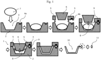
- a mold 1 of the present invention for molding a glass-made optical component is comprised of a female mold 2, a molding mold 4, a ring mold 5 and a male mold 6.
- a lump of molten glass (molten glass gob 7) which is a material of the glass-made optical component is introduced into a concave surface 3 of the female mold 2.
- the male mold 6 has a convex surface, and the male mold 6 is used for pressing the molten glass gob 7 from above.
- the present invention is not the method of obtaining the molded article by directory transferring the shape of the mold formed by the female mold 2 and the male mold 6, but the present invention is the method where the molten glass gob 7 introduced into the female mold 2 is raised upward along the concave surface 3 of the female mold and reaches the outer peripheral portion when the molten glass gob 7 is pressed by the male mold 6, and the molten glass is injected and filled into the space of the molding mold 4 formed between a lower mold 4a of the molding mold 4 provided on the outer peripheral portion and an upper mold 4b of the molding mold provided on the lower surface of the ring mold 5 through an inlet 8 of the molten glass gob to form the glass-made optical component 11.
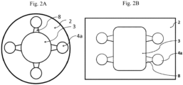
- a plurality of lower molds 4a of the molding mold 4 for molding the glass-made optical component 11 is concentrically provided on the outer peripheral portion of the concave surface of the female mold 2 centered around a center axis of the concave surface, a plurality of upper molds 4b of the molding mold 4 is concentrically provided on the ring mold 5 so as to be aligned with positions of the lower molds 4a which are concentrically provided, and a plurality of glass-made optical components 11 can be molded by one press operation.
- the productivity of the same optical components can be increased.
- plurality kinds of optical components can be molded by one press operation.
- the present invention is not necessarily limited to the configuration of concentrically arranging a plurality of molding molds.
- a female mold having an approximately rectangular shape in plan view is used, a concave surface having an approximately rectangular shape in plan view is provided on the female mold, and a plurality of molding molds is arranged in parallel on the peripheral portion of the concave surface ( Fig. 2B ).
- the lower mold 4a of the molding mold 4 for molding the glass-made optical component 11 can be integrated with the female mold 2 when the lower mold 4a is fitted in the female mold 2
- the upper mold 4b of the molding mold 4 can be integrated with the ring mold 5 when the upper mold 4b is fitted in the ring mold 5
- the lower mold 4a of the molding mold can be removed from the female mold 2
- the upper mold 4b of the molding mold can be removed from the ring mold 5
- the lower mold 4a of the molding mold 4 and the upper mold 4b of the molding mold 4 can be replaced according to the shape of the glass-made optical component 11.
- An example of a detachable mechanism of the molding mold is shown in Fig. 3 . In this case, the molding mold is fixed to the ring mold by bolt-tightening.
- the space 9 formed between the lower mold 4a and the upper mold 4b of the molding mold 4 for molding the glass-made optical component 11 during a pressing process is a space (main space) which has the shape corresponding to the shape of the glass-made optical component 11.
- an additional space 12 which is formed outside the space 9 is provided so that the molten glass gob can flow into the additional space 12 since the molten glass gob can be more surely injected into the space 9.
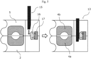
- a mold lock mechanism 13 is further provided to tighten the female mold 2 and the ring mold 5 with each other during a pressing process.
- the mold lock mechanism is comprised of a lock bar 15 which is synchronously lowered with the male mold 6, a rotary hook 16 which is fixed to the female mold 2, and a lock plate 17 which is fixed to the ring mold 5.
- the rotary hook 16 and the lock plate 17 are locked with each other when the lock bar 15 is lowered synchronously with the male mold 6 and the tip of the lock bar pushes and rotates the rotary hook 16. Consequently, the female mold 2 and the ring mold 5 are also tightened and locked with each other.
- a bored hole 14 is formed on at least one of the lower mold 4a and the upper mold 4b of the molding mold 4 for molding the glass-made optical component 11 so that air pressed by the molten glass gob is released from the main space which has the shape corresponding to the shape of the glass-made optical component 11 during the pressing process. Since the air existed in the space is released from the bored hole when the molten glass gob is injected into the space through the inlet 8 of the molten glass gob, it is expected that the dimensional precision of the optical component can be increased.
- an inner diameter of the bored hole is 0.1 mm or more and 0.5 mm or less. The above described inner diameter is large enough for releasing the air and small enough for preventing the molten glass from flowing in the bored hole.
- the second invention of the present invention discloses a method of molding a glass-made optical component having a precise and complicated three-dimensional shape by using the mold for molding the glass-made optical component according to any one of claims 1 to 7, the method comprising:
- the above described processes (1) to (6) are sequentially performed in the present invention for molding a glass-made optical component having a precise and complicated three-dimensional shape by using the above described mold. It is required that the pressing process is continued until the temperature of the molten glass gob injected into the molding mold 4 becomes equal to or lower than the annealing point of the molten glass.
- the annealing point is defined as the temperature higher than the glass transition point by approximately 20°C and an internal strain of the glass is substantially removed for 15 minutes at the annealing point. Actually, the glass is almost solidified at the annealing point.
- the dimension of the optical component cannot be stably specified.
- the temperature of the glass becomes equal to or lower than the annealing point and the glass is solidified can be experientially understood from the time elapsed after pressing.
- it is preferred that a thermocouple is installed around the molding mold of the ring mold to measure the temperature.
- the article primary obtained by the above described method is the glass molded body formed in the female mold, the male mold, the ring mold and the molding mold, the process of cutting the glass-made optical component from the molded body as the final product is required. If required, grinding process and polishing process of the cut surface and end surface are performed after the cutting process in some cases.
- the weight of the molten glass gob introduced in the concave surface 3 of the female mold is 6 to 70 times, more preferably 8 to 70 times, heavier than the weight of the glass molded body formed in the molding mold.
- the weight ratio is specified as described above, the flow of the molten glass gob can be kept sufficiently and the molten glass gob can be surely injected into the space 9 (alternatively, the space of both the space 9 and the additional space 12 formed outside the space 9) for obtaining the glass-made optical component through the inlet 8 of the molten glass gob. If the weight is less than 6 times, the flow cannot be kept sufficiently, and thus the glass-made optical component cannot be molded. If the weight exceeds 70 times, the molten glass gob flows out from the space between the ring mold and the male mold, and thus the pressing pressure becomes insufficient.
- glass-made optical components having a precise and complicated three-dimensional shape can be molded by a new mold for molding a glass and a molding method of the glass using new mold although they cannot be obtained from the conventional mold and molding method.
- a special mold material and non-oxidizing atmosphere are not required unlike the mold pressing method, and the present invention enables mass production or multi-kind and small-quantity production.
- the present invention largely contributes to the development of industry.
- a mold 1 for molding a glass-made optical component 11 is produced by cutting and polishing a stainless steel according to a design drawing.
- a heat-resistant alloy having higher durability can be used for the molding mold 4 if required.
- the mold for molding the glass-made optical component of the present invention is comprised of a female mold 2, a molding mold 4, a ring mold 5 and a male mold 6.
- a concave surface 3 is formed on the female mold 2 to introduce a lump of molten glass (molten glass gob 7) made of a material of the glass-made optical component on the concave surface 3.
- a lower mold 4a of a molding mold 4 for molding a glass-made optical component 11 is formed on an outer peripheral portion of the female mold 2.
- an upper mold 4b of the molding mold 4 is provided on a lower surface side of the ring mold 5 so that the upper mold 4b is located opposite to the lower mold 4a formed on the outer peripheral portion of the female mold 2.
- the ring mold 5 is first lowered and closely in contact with the female mold 2.
- a space sandwiched between the lower mold 4a of the molding mold 4 formed on the outer peripheral portion of the female mold 2 and the upper mold 4b of the molding mold formed on the lower surface portion of the ring mold 5 is formed.
- the male mold 6 having the convex surface is lowered.
- the molten glass gob 7 is pressed from above.
- the molten glass gob is raised upward along an inner surface of the concave surface 3 of the female mold 2 and reaches the outer peripheral portion while keeping sufficient fluidity, and the molten glass is injected into the space of the molding mold 4 sandwiched between the lower mold 4a and the upper mold 4b to form the glass-made optical component 11.
- the later described mold lock mechanism 13 is preferably used for certainly tightening the female mold 2 and the ring mold 5.
- the mold 1 for molding the glass-made optical component 11 further has the features shown in Figs. 2 to 6 . The features will be explained by using each drawing.
- Fig. 2A shows an example of the female mold 2 where four lower molds 4a of the molding mold 4 for forming the glass-made optical component 11 are concentrically provided on the outer peripheral portion of the concave surface 3 of the female mold 2 around a center axis of the concave surface 3.
- Four upper molds 4b of the molding mold 4 are concentrically provided on the lower surface side of the ring mold 5 so as to be aligned with positions of the four lower molds 4a.
- this mold has a structure capable of simultaneously molding four glass-made optical components 11 by one press operation.
- the number of the molding molds 4 can be increased to six or eight, for example.
- the present invention can contribute to increase the productivity of the same optical components. In some cases, when the molding molds 4 having different shapes are provided, plurality kinds of optical components can be molded by one press operation.
- Fig. 3 shows the upper mold 4b of the molding mold 4 provided on the lower surface side of the ring mold 5.
- the upper mold 4b is fixed to the ring mold 5 by bolt-tightening or the like and the upper mold 4b has a structure detachable from the ring mold 5.
- the lower mold 4a of the molding mold 4 also has a structure detachable from the female mold 2 by an arbitrary method such as bolt-tightening (not illustrated).
- it is possible to mold the optical components having various shapes by replacing the lower mold 4a of the molding mold 4 and the upper mold 4b of the molding mold 4 while the female mold 2, the male mold 6 and the ring mold 5 are not replaced.
- the above described features shows that the present invention is suitable for mass production or multi-kind and small-quantity production.
- Fig. 4 shows the mold structure having a space (main space) 9 sandwiched by the lower mold 4a and the upper mold 4b of the molding mold 4 (i.e., space 9 having the shape corresponding to the shape of the glass-made optical component 11) and further having an additional space 12 formed outside the space 9.
- the additional space 12 is not provided, the glass-made optical component 11 may become a defective depending on the shape of the optical component since the molten glass gob 7 may not flow to the corners of the space 9 having the shape corresponding to the shape of the glass-made optical component 11 while forming a clearance.
- the additional space 12 is provided, the molten glass gob 7 can be surely injected and filled to at least the corners of the space 9 having the shape corresponding to the shape of the glass-made optical component 11.
- Fig. 5 shows that the mold structure has the mold lock mechanism 13 for tightening the female mold 2 and the ring mold 5 with each other.
- the mold lock mechanism 13 for tightening the female mold 2 and the ring mold 5 with each other.
- Fig. 6 shows an example of the mold where a bored hole 14 is formed on the upper mold 4b of the molding mold 4 for releasing the air pressed by the molten glass gob 7 from the space 9 which has the shape corresponding to the shape of the glass-made optical component 11 during the pressing process.
- the mold has the structure of releasing the air existed in the space 9 from the bored hole 14, it is expected that the occurrence of the shape defects can be prevented and the dimensional precision of the optical component can be increased.
- the inner diameter of the bored hole 14 is specified to 0.3 mm.
- the manufacturing method of the glass-made optical component concerning the present invention is the manufacturing method of molding a glass-made optical component having a precise and complicated three-dimensional shape by using the above described mold for molding the glass-made optical component.
- the explanation will be made by using Fig. 1 (and Fig. 4 ).
- a glass-made optical component having precise and complicated three-dimensional shape can be manufactured by:
- the pressing process is continued until the temperature of the molten glass gob 7 injected into the molding mold 4 becomes equal to or lower than the annealing point of the molten glass.
- a molded article having high dimensional precision can be obtained by the pressing the glass for 10 to 30 seconds, for example, for continuously applying the pressure to the glass until the glass is solidified. Since the article primary obtained by the above described method is the glass molded body 10 formed in the female mold 2, the male mold 6, the ring mold 5 and the molding mold 4, the process of cutting the glass-made optical component 11 from the molded body 10 as the final product is required. If required, grinding process and polishing process of the cut surface and end surface are performed after the cutting process in some cases.
- the weight of the molten glass gob 7 introduced in the concave surface 3 of the female mold 2 is preferably 6 to 70 times, more preferably 8 to 70 times, heavier than the weight of the glass molded body formed in the molding mold 4.
- the weight ratio is specified as described above, the flow of the molten glass gob 7 can be kept sufficiently and the molten glass gob 7 can be surely injected into the space 9 (alternatively, the space of both the space 9 and the additional space 12 formed outside the space 9) for obtaining the glass-made optical component 11 through the inlet 8 of the molten glass gob.
- the weight is less than 6 times, the flow cannot be kept sufficiently, and thus the glass-made optical component cannot be molded.
- the weight exceeds 70 times, the molten glass gob flows out from the space between the ring mold and the male mold, and thus the pressing pressure becomes insufficient.
- the pressing between the female mold 2 and the male mold 6 is performed for making the molten glass gob 7 flow, and thus the molten glass gob 7 is injected into the space 9 formed by the molding mold 4 provided on the peripheral portion of the female mold 2 and the lower surface of the ring mold 5 to obtain the final product 11.
- the present invention is completely different from the mold and the manufacturing method of the conventional direct press method where the final product is simply and directly pressed by the female mold and the male mold.
- the present invention takes over the advantage of the direct press method where the cycle time of the pressing process is short.
- the present invention is the manufacturing method suitable for mass producing a glass-made optical component having precise and complicated three-dimensional shape.
- a glass-made optical component having a precise three-dimensional shape was molded by using the above described mold and the above described molding method.
- the working examples are shown in Table 1.
- a general borosilicate glass having the thermal expansion coefficient of approximately 55 ⁇ 10 -7 /°C was used as for the glass.
- the temperature of the molten glass gob was approximately 1,000°C when the molten glass gob was introduced into the female mold. Note that the annealing point of this glass is approximately 500°C.
- the group 1 shows the molded result using the design drawing shown in Fig. 7 .
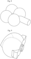
- a glass-made optical component having a complicated shape formed by combining plural free-form surfaces and flat surfaces as shown in Fig. 8 was molded.
- a weight W1 of the molded glass-made optical component was approximately 15 g.
- the glass-made optical component can be obtained by removing the glass molded in the female mold, the male mold, the ring mold and the molding mold from these molds, and cutting the portion of the glass-made optical component (i.e., final product) from the molded glass removed from the molds.
- the moldability and the outer appearance of the molded glass-made optical component were evaluated by changing a weight W2 of the molten glass gob introduced into the concave surface of the female mold.
- the pressing pressure applied from the male mold to the molten glass gob was approximately 3.1 MPa, and the pressing time was approximately 23 to 27 seconds in accordance with the weight of the molten glass gob.
- the weight of the molten glass gob was 200 g to 900 g, there was no problem in the moldability and the outer appearance of the obtained glass-made optical component was good.
- the weight of the molten glass gob was controlled to a predetermined weight by a furnace for feeding the molten glass.
- the weight of the introduced molten glass gob was calculated by measuring the solidified glass molded body 10 by a balance after the pressing process. The same can be applied to the following working examples.
- the group 2 shows a result of molding glass-made optical components having a complicated shape formed by combining plural free-form surfaces and flat surfaces.
- the group 2 four glass-made optical components were manufactured by one press operation by using the molding mold using the female mold as shown in Fig. 2A .
- Table 1 shows the result where the test was performed in six standards of the weight of the molten glass gob from 100 g to 1,100 g. When the molten glass gob was 100 g (W2/W1 was approximately 2), the molten glass did not reach even to the inlet of the molten glass gob, and it was impossible to mold the glass-made optical component.
- the molten glass gob was 500 g or more (W2/W1 was approximately 8 or more), sufficient amount of the molten glass was raised upward along the concave surface of the female mold, reached the inlet of the molten glass gob, and injected into the space for molding the glass-made optical component to fill the space.
- the moldability was good.
- the outer appearance of the obtained glass-made optical component was the designed shape.
- the pressing could be performed by the male mold without problems.
- the group 3 shows an example of molding glass-made optical components (weight of one component is 15 g) having a convex shape on both surfaces as shown in Fig. 9 .
- Table 1 shows the result where the test was performed in six standards of the weight of the molten glass gob from 100 g to 1,100 g.
- the molten glass gob was 100 g (W2/W1 was approximately 1), the molten glass did not reach even to the inlet of the molten glass gob, and it was impossible to mold the glass-made optical component.
- the molten glass gob was 300 g (W2/W1 was approximately 3) and 500 g (W2/W1 was approximately 4), although the molten glass passed through the inlet of the molten glass gob and injected into the space for molding the glass-made optical component, the amount was insufficient and the glass-made optical component was incompletely molded.
- the molten glass gob was 700 g or more (W2/W1 was approximately 6 or more), sufficient amount of the molten glass was raised upward along the concave surface of the female mold, reached the inlet of the molten glass gob, and injected into the space for molding the glass-made optical component to fill the space.
- the moldability was good.
- the outer appearance of the obtained glass-made optical component was the designed shape.
- the pressing can be performed by the male mold without problems.
- the following processes are considered to be performed that the molten glass gob is pressed by the male mold in a state that the molten glass gob have sufficient temperature and fluidity, the molten glass is raised upward along the concave surface of the female mold and reaches the inlet of the molten glass gob, the molten glass gob passes through the inlet of the molten glass gob and injected into the molding mold while keeping sufficient temperature and fluidity, and heat of the glass is taken in the molding mold and the glass is solidified, and thus the glass-made optical component having a target shape can be obtained.
- the pressed molten glass gob existed in the concave surface of the female mold is solidified.
- the moldability, the shape accuracy of the glass-made optical component and releasability become the appropriate condition.
- the weight of the introduced glass gob with respect to the product weight, the pressing pressure and the pressing time should be appropriately adjusted.
Landscapes
- Physics & Mathematics (AREA)
- Engineering & Computer Science (AREA)
- Chemical & Material Sciences (AREA)
- General Physics & Mathematics (AREA)
- Optics & Photonics (AREA)
- Manufacturing & Machinery (AREA)
- Materials Engineering (AREA)
- Organic Chemistry (AREA)
- Glass Compositions (AREA)
- Moulds For Moulding Plastics Or The Like (AREA)
Claims (10)
- Form zum Formen einer aus Glas hergestellten optischen Komponente mit einer präzisen und komplizierten dreidimensionalen Gestalt, die Form umfassend:eine Matrize, die eine untere Form von mindestens einer Formungsform zum Formen der aus Glas hergestellten optischen Komponente auf einem äußeren Umfangsabschnitt einer konkaven Oberfläche der Matrize aufweist;eine Patrize, die eine mit der konkaven Oberfläche der Matrize kombinierten konvexe Oberfläche aufweist; undeine Ringform, die an einem äußeren Umfangsabschnitt der Patrize angeordnet ist, wobei die Ringform eine obere Form der mindestens einen Formungsform zum Formen der aus Glas hergestellten optischen Komponente aufweist, wobeisowohl die untere Form der Formungsform als auch die obere Form der Formungsform Matrizen mit einer konkaven Gestalt sind, und wobeiein in die konkave Oberfläche der Matrize eingeführter geschmolzener Glastropfen konfiguriert ist, um von oben durch die Patrize mit der konvexen Oberfläche gedrückt zu werden, so dass der geschmolzene Glastropfen in einen zwischen der unteren Form und der oberen Form der mindestens einen Formungsform eingespritzt wird.
- Form zum Formen der aus Glas hergestellten optischen Komponente nach Anspruch 1, wobeieine Vielzahl von unteren Formen der Formungsform zum Formen der aus Glas hergestellten optischen Komponente konzentrisch auf dem äußeren Umfangsabschnitt der konkaven Oberfläche der Matrize, zentriert um eine Mittelachse der konkaven Oberfläche, bereitgestellt ist,eine Vielzahl von oberen Formen der Formungsform konzentrisch auf der Ringform vorgesehen ist, um mit den Positionen der unteren Formen, die konzentrisch bereitgestellt sind, ausgerichtet zu sein, undeine Vielzahl von aus Glas hegestellten optischen Komponenten in einem Pressvorgang geformt werden kann.
- Form zum Formen der aus Glas hergestellten optischen Komponente nach Anspruch 1 oder 2, wobei
die untere Form der Formungsform zum Formen der aus Glas hergestellten optischen Komponente in die Matrize integriert werden kann, wenn die untere Form in die Matrize eingepasst ist,die obere Form der Formungsform in die Ringform integriert werden kann, wenn die obere Form in die Ringform eingepasst ist,die untere Form der Formungsform von der Matrize entfernt werden kann, die obere Form der Formungsform von der Ringform entfernt werden kann, unddie untere Form der Formungsform und die obere Form der Formungsform entsprechend der Gestalt der aus Glas hergestellten optischen Komponente ausgetauscht werden kann. - Form zum Formen der aus Glas hergestellten optischen Komponente nach einem der Ansprüche 1 bis 3, wobei
der zwischen der unteren Form und der oberen Form der Formungsform zum Formen der aus Glas hergestellten optischen Komponente während eines Pressvorgangs gebildete Raum einen Hauptraum aufweist, der die Gestalt aufweist, die der Gestalt der aus Glas hergestellten optischen Komponente entspricht, und einen zusätzlichen Raum der außerhalb des Hauptraums gebildet ist, so dass der geschmolzene Glastropfen in den zusätzlichen Raum fließen kann. - Form zum Formen der aus Glas hergestellten optischen Komponente nach einem der Ansprüche 1 bis 4, wobei
die Form ferner einen Formverriegelungsmechanismus umfasst, der die Matrize und die Ringform während eines Pressvorgangs miteinander verspannt. - Form zum Formen der aus Glas hergestellten optischen Komponente nach einem der Ansprüche 1 bis 5, wobei
ein Bohrloch auf mindestens einer der unteren Form und der oberen Form der Formungsform zum Formen der aus Glas hergestellten optischen Komponente gebildet ist, so dass durch den geschmolzenen Glastropfen gedrückte Luft aus dem Hauptraum entweicht, der Gestalt aufweist, die der Gestalt der aus Glas hegestellten Komponente während eines Pressvorgangs entspricht. - Form zum Formen der aus Glas hergestellten optischen Komponente nach Anspruch 6, wobei
ein Innendurchmesser des Bohrlochs 0,1 mm oder mehr und 0,5 mm oder weniger beträgt. - Form zum Formen einer aus Glas hergestellten optischen Komponente mit einer präzisen und komplizierten dreidimensionalen Gestalt durch Verwenden der Form zum Formen der aus Glas hergestellten Komponente nach einem der Ansprüche 1 bis 7, das Verfahren umfassend:(1) einen Vorgang zum Einführen des geschmolzenen Glastropfens in einen zentralen Teil der konkaven Oberfläche der Matrize, auf der die untere Form der Formungsform zum Formen der aus Glas hergestellten optischen Komponente am äußeren Umfangsabschnitt bereitgestellt ist;(2) einen Vorgang zum Absenken der Ringform, um in engem Kontakt mit der Matrizenform zu sein, so dass die obere Form der Formungsform, die auf einer unteren Oberfläche der Ringform gebildet ist, in engem Kontakt mit der unteren Form der Formungsform ist, die auf dem äußeren Umfangsabschnitt der Matrizenform gebildet ist, um einen Hauptraum in der Formungsform zu bilden, wobei der Hauptraum die Gestalt aufweist, die der Gestalt der aus Glas hergestellten optischen Komponente entspricht;(3) einen Vorgang zum Pressen des geschmolzenen Glastropfens, der in den zentralen Teil der konkaven Oberfläche der Matrize von oben durch die Patrize mit der konvexen Oberfläche eingeführt wird;(4) einen Vorgang zum weiteren Pressen des geschmolzenen Glastropfens durch die Patrize, so dass der geschmolzene Glastropfen entlang einer inneren Oberfläche der konkaven Oberfläche der Matrize nach oben fließt und der geschmolzene Glastropfen durch einen Einlass des geschmolzenen Glastropfens in den in der Formungsform gebildeten Raum eingespritzt wird;(5) einen Vorgang zum Ziehen der Patrize und dann der Ringform nach oben, nachdem die Temperatur des in die Formungsform eingespritzten geschmolzenen Glastropfens gleich oder geringer als ein Kühlpunkt des geschmolzenen Glases ist und das geschmolzene Glas erstarrt ist; und(6) einen Vorgang zum Entfernen eines verfestigten Glasformkörpers, der in dem Raum der Matrize, der Patrize, der Ringform und der Formungsform gebildet wurde, und zum anschließenden Schneiden der in der Formungsform geformten aus Glas hergestellten optischen Komponente.
- Verfahren zum Formen einer aus Glas hergestellten optischen Komponente mit einer präzisen und komplizierten dreidimensionalen Gestalt nach Anspruch 8, wobei
das Gewicht des geschmolzenen Glastropfens, der in die konkave Oberfläche der Matrize eingeführt wird, 6- bis 70-mal schwerer als das Gewicht der in der Formungsform geformten aus Glas hergestellten optischen Komponente ist. - Verfahren zum Formen einer aus Glas hergestellten optischen Komponente mit einer präzisen und komplizierten dreidimensionalen Gestalt nach Anspruch 8, wobei
das Gewicht des geschmolzenen Glastropfens, der in die konkave Oberfläche der Matrize eingeführt wird, 8- bis 70-mal schwerer als das Gewicht der in der Formungsform geformten aus Glas hergestellten optischen Komponente ist.
Applications Claiming Priority (2)
| Application Number | Priority Date | Filing Date | Title |
|---|---|---|---|
| JP2018078780 | 2018-04-17 | ||
| PCT/JP2019/003785 WO2019202816A1 (ja) | 2018-04-17 | 2019-02-04 | ガラス製光学部品成形用金型並びにその金型を用いたガラス製光学部品の製造方法 |
Publications (3)
| Publication Number | Publication Date |
|---|---|
| EP3686164A1 EP3686164A1 (de) | 2020-07-29 |
| EP3686164A4 EP3686164A4 (de) | 2020-10-28 |
| EP3686164B1 true EP3686164B1 (de) | 2024-03-20 |
Family
ID=68238866
Family Applications (1)
| Application Number | Title | Priority Date | Filing Date |
|---|---|---|---|
| EP19788940.5A Active EP3686164B1 (de) | 2018-04-17 | 2019-02-04 | Form zum formen für eine aus glas hergestellte optische komponente und verfahren zur herstellung einer aus glas hergestellten optischen komponente unter verwendung dieser form |
Country Status (6)
| Country | Link |
|---|---|
| US (1) | US20200339463A1 (de) |
| EP (1) | EP3686164B1 (de) |
| JP (1) | JP6739131B2 (de) |
| CN (1) | CN111094195B (de) |
| TW (1) | TWI721368B (de) |
| WO (1) | WO2019202816A1 (de) |
Families Citing this family (5)
| Publication number | Priority date | Publication date | Assignee | Title |
|---|---|---|---|---|
| JP6964050B2 (ja) * | 2018-07-20 | 2021-11-10 | オリンパス株式会社 | 光学素子の製造方法 |
| CN111574032B (zh) * | 2020-04-02 | 2025-04-08 | 苏州卡利肯新光讯科技有限公司 | 一种玻璃透镜成型模具 |
| CN113894955B (zh) * | 2021-08-27 | 2023-09-22 | 中国人民解放军第五七二一工厂 | 一种飞行器风挡玻璃钻孔工装及其制作方法 |
| WO2025015342A2 (en) * | 2023-07-13 | 2025-01-16 | Arizona Board Of Regents On Behalf Of The University Of Arizona | A telescope for mass production at low cost |
| JP7645587B1 (ja) * | 2024-10-10 | 2025-03-14 | 岡本硝子株式会社 | ガラス製光学部品成形用金型 |
Family Cites Families (35)
| Publication number | Priority date | Publication date | Assignee | Title |
|---|---|---|---|---|
| GB182419A (en) * | 1921-07-01 | 1922-11-23 | Isaiah Frank | Method of and apparatus for casting ophthalmic lenses |
| US3214258A (en) * | 1959-10-30 | 1965-10-26 | Maquinas Fabricacion Sa De | Blank mold means with pneumatic operated plunger for fabricating seamless high optical quality glass articles |
| US3814593A (en) * | 1970-10-21 | 1974-06-04 | Ppg Industries Inc | Pressure molding of glass articles apparatus |
| US3844755A (en) * | 1972-11-16 | 1974-10-29 | Eastman Kodak Co | Method and apparatus for transfer molding glass lenses |
| FR2395959A1 (fr) * | 1977-06-28 | 1979-01-26 | Corning Glass Works | Procede de realisation d'un bec verseur au cours du pressage d'articles en verre, et articles ainsi obtenus |
| US4132538A (en) * | 1977-08-29 | 1979-01-02 | Corning Glass Works | Injection molding hydrosilicates |
| US4614630A (en) * | 1984-04-02 | 1986-09-30 | Minnesota Mining And Manufacturing Co. | Mold having ceramic insert, method for injection molding using the same |
| JPS61251529A (ja) | 1985-04-30 | 1986-11-08 | Olympus Optical Co Ltd | ガラス光学部品の高精密成形方法 |
| JPS62216928A (ja) * | 1986-03-19 | 1987-09-24 | Canon Inc | 硝子成形型 |
| JPH02196038A (ja) | 1989-01-23 | 1990-08-02 | Olympus Optical Co Ltd | ガラス成形方法及び成形装置 |
| JP3164404B2 (ja) * | 1992-02-21 | 2001-05-08 | オリンパス光学工業株式会社 | ガラス光学素子の成形装置と成形方法 |
| JPH05254858A (ja) | 1992-03-09 | 1993-10-05 | Sumitomo Heavy Ind Ltd | 成形方法 |
| JP3266659B2 (ja) * | 1992-09-11 | 2002-03-18 | 旭光学工業株式会社 | 光学素子成形用の成形型及び光学素子の成形方法 |
| JP3299785B2 (ja) * | 1992-09-11 | 2002-07-08 | オリンパス光学工業株式会社 | 光学ガラスレンズの製造方法 |
| JP2631064B2 (ja) * | 1993-01-20 | 1997-07-16 | 株式会社日本製鋼所 | フローモールド成形方法 |
| JPH06279040A (ja) | 1993-03-29 | 1994-10-04 | Japan Steel Works Ltd:The | 低融点ガラスの成形方法及び低融点ガラス成形品 |
| JPH06305746A (ja) * | 1993-04-22 | 1994-11-01 | Sumitomo Heavy Ind Ltd | 光学ガラスレンズ用成形型 |
| JPH07206455A (ja) * | 1993-12-31 | 1995-08-08 | Olympus Optical Co Ltd | 光学素子の成形方法及び装置 |
| JP3789968B2 (ja) | 1996-02-29 | 2006-06-28 | 旭テクノグラス株式会社 | 非球面レンズの成形方法 |
| JP3817789B2 (ja) * | 1996-09-03 | 2006-09-06 | フジノン株式会社 | 光学部品成形装置 |
| JPH10101347A (ja) * | 1996-09-24 | 1998-04-21 | Fuji Photo Optical Co Ltd | 光学部品の射出成形装置及び射出成形方法 |
| JP2000001320A (ja) * | 1998-06-15 | 2000-01-07 | Canon Inc | 光学素子またはその製造用素材としてのガラス塊の成形方法 |
| JP2000275479A (ja) | 1999-03-26 | 2000-10-06 | Ngk Insulators Ltd | 複数段v溝を有するv溝基板及びその製造方法 |
| JP2002097025A (ja) * | 2000-09-21 | 2002-04-02 | Canon Inc | 光学素子成形用素材およびこれを用いた光学素子成形方法 |
| JP2002114529A (ja) * | 2000-10-03 | 2002-04-16 | Matsushita Electric Ind Co Ltd | 光学素子の成形金型および光学素子の製造方法 |
| US20030145626A1 (en) * | 2001-02-13 | 2003-08-07 | Eastman Kodak Company | Apparatus and method for molding glass optical elements |
| EP1443344A1 (de) * | 2003-01-29 | 2004-08-04 | Heptagon Oy | Herstellung von mikrostrukturierten Teilen |
| JP2008257261A (ja) * | 2003-03-28 | 2008-10-23 | Matsushita Electric Ind Co Ltd | 光学素子及び光学素子成形型及び光学素子成形方法 |
| JP3961474B2 (ja) * | 2003-11-18 | 2007-08-22 | 日本ピラー工業株式会社 | ガラスレンズ成形用金型 |
| US20070216048A1 (en) * | 2006-03-20 | 2007-09-20 | Heptagon Oy | Manufacturing optical elements |
| WO2012026263A1 (ja) * | 2010-08-25 | 2012-03-01 | コニカミノルタオプト株式会社 | ガラス成形体の製造方法および製造装置 |
| JP5751209B2 (ja) * | 2012-05-09 | 2015-07-22 | コニカミノルタ株式会社 | ガラス板の製造方法及び製造装置 |
| WO2014203636A1 (ja) * | 2013-06-18 | 2014-12-24 | コニカミノルタ株式会社 | ガラス成形品の製造方法および製造装置 |
| TWI614107B (zh) * | 2015-07-15 | 2018-02-11 | 趙崇禮 | 透鏡陣列的模具設備及其使用方法 |
| CN110683745B (zh) * | 2019-09-26 | 2022-02-11 | 宁波大学 | 一种硫系玻璃微透镜的注模制备装置及制备方法 |
-
2019
- 2019-01-22 TW TW108102385A patent/TWI721368B/zh active
- 2019-02-04 WO PCT/JP2019/003785 patent/WO2019202816A1/ja not_active Ceased
- 2019-02-04 EP EP19788940.5A patent/EP3686164B1/de active Active
- 2019-02-04 US US16/757,416 patent/US20200339463A1/en not_active Abandoned
- 2019-02-04 CN CN201980004369.0A patent/CN111094195B/zh active Active
- 2019-02-04 JP JP2020513981A patent/JP6739131B2/ja active Active
Also Published As
| Publication number | Publication date |
|---|---|
| EP3686164A1 (de) | 2020-07-29 |
| TW201943659A (zh) | 2019-11-16 |
| US20200339463A1 (en) | 2020-10-29 |
| WO2019202816A1 (ja) | 2019-10-24 |
| TWI721368B (zh) | 2021-03-11 |
| JPWO2019202816A1 (ja) | 2020-08-06 |
| JP6739131B2 (ja) | 2020-08-12 |
| EP3686164A4 (de) | 2020-10-28 |
| CN111094195B (zh) | 2022-06-24 |
| CN111094195A (zh) | 2020-05-01 |
Similar Documents
| Publication | Publication Date | Title |
|---|---|---|
| EP3686164B1 (de) | Form zum formen für eine aus glas hergestellte optische komponente und verfahren zur herstellung einer aus glas hergestellten optischen komponente unter verwendung dieser form | |
| US4738703A (en) | Method of molding optical lenses | |
| US5588980A (en) | Apparatus for molding a glass optical element with a transporting supporting member | |
| JPH10101347A (ja) | 光学部品の射出成形装置及び射出成形方法 | |
| US5987922A (en) | Manufacturing method for molded glass articles | |
| KR20170006017A (ko) | 몰드성형 공정에 적합한 칼코지나이드계 렌즈 조성물 및 이를 이용한 렌즈 제조방법 | |
| JPH07330347A (ja) | 光学素子成形方法 | |
| TW201144024A (en) | Plastics molding system and optical element formed by the same | |
| US20070204655A1 (en) | Method of manufacturing optical glass element | |
| JP2000001320A (ja) | 光学素子またはその製造用素材としてのガラス塊の成形方法 | |
| US20260103418A1 (en) | Mold for molding glass-made optical component | |
| JPH0435427B2 (de) | ||
| JP2746454B2 (ja) | 光学素子の成形方法 | |
| EP0506131B1 (de) | Verfahren zur Herstellung von Glasrohlingen | |
| JP2662300B2 (ja) | ガラス成形品の製造方法および装置 | |
| JPH0826739A (ja) | ガラス素子の製造方法及び装置 | |
| JP2618527B2 (ja) | 光学部品の製造法 | |
| JPS63162539A (ja) | 光学部品の成形方法 | |
| JPH01212240A (ja) | 光学素子の成形装置 | |
| JP2003238171A (ja) | ガラス光学素子の製造方法 | |
| JP2023127555A (ja) | 平盤状ガラスの製造方法とその製造装置、及びガラス基板の製造方法 | |
| JPS61197429A (ja) | 高い表面品質を有するガラス成形品の製造方法 | |
| JP2005305797A (ja) | 光学素子成形型、光学素子成形方法及び光学素子 | |
| CN100404449C (zh) | 铸模加压成形装置及光学元件的制造方法 | |
| JP2012158490A (ja) | 光学素子の製造装置及び光学素子の製造方法 |
Legal Events
| Date | Code | Title | Description |
|---|---|---|---|
| STAA | Information on the status of an ep patent application or granted ep patent |
Free format text: STATUS: THE INTERNATIONAL PUBLICATION HAS BEEN MADE |
|
| PUAI | Public reference made under article 153(3) epc to a published international application that has entered the european phase |
Free format text: ORIGINAL CODE: 0009012 |
|
| STAA | Information on the status of an ep patent application or granted ep patent |
Free format text: STATUS: REQUEST FOR EXAMINATION WAS MADE |
|
| 17P | Request for examination filed |
Effective date: 20200420 |
|
| AK | Designated contracting states |
Kind code of ref document: A1 Designated state(s): AL AT BE BG CH CY CZ DE DK EE ES FI FR GB GR HR HU IE IS IT LI LT LU LV MC MK MT NL NO PL PT RO RS SE SI SK SM TR |
|
| AX | Request for extension of the european patent |
Extension state: BA ME |
|
| REG | Reference to a national code |
Ref country code: DE Ref legal event code: R079 Free format text: PREVIOUS MAIN CLASS: C03B0011000000 Ipc: C03B0011080000 Ref document number: 602019048667 Country of ref document: DE |
|
| A4 | Supplementary search report drawn up and despatched |
Effective date: 20200928 |
|
| RIC1 | Information provided on ipc code assigned before grant |
Ipc: G02B 3/00 20060101ALI20200922BHEP Ipc: C03B 11/08 20060101AFI20200922BHEP |
|
| STAA | Information on the status of an ep patent application or granted ep patent |
Free format text: STATUS: EXAMINATION IS IN PROGRESS |
|
| 17Q | First examination report despatched |
Effective date: 20201106 |
|
| DAV | Request for validation of the european patent (deleted) | ||
| DAX | Request for extension of the european patent (deleted) | ||
| GRAP | Despatch of communication of intention to grant a patent |
Free format text: ORIGINAL CODE: EPIDOSNIGR1 |
|
| STAA | Information on the status of an ep patent application or granted ep patent |
Free format text: STATUS: GRANT OF PATENT IS INTENDED |
|
| GRAS | Grant fee paid |
Free format text: ORIGINAL CODE: EPIDOSNIGR3 |
|
| GRAA | (expected) grant |
Free format text: ORIGINAL CODE: 0009210 |
|
| STAA | Information on the status of an ep patent application or granted ep patent |
Free format text: STATUS: THE PATENT HAS BEEN GRANTED |
|
| INTG | Intention to grant announced |
Effective date: 20240125 |
|
| AK | Designated contracting states |
Kind code of ref document: B1 Designated state(s): AL AT BE BG CH CY CZ DE DK EE ES FI FR GB GR HR HU IE IS IT LI LT LU LV MC MK MT NL NO PL PT RO RS SE SI SK SM TR |
|
| REG | Reference to a national code |
Ref country code: GB Ref legal event code: FG4D |
|
| REG | Reference to a national code |
Ref country code: CH Ref legal event code: EP |
|
| REG | Reference to a national code |
Ref country code: IE Ref legal event code: FG4D |
|
| REG | Reference to a national code |
Ref country code: DE Ref legal event code: R096 Ref document number: 602019048667 Country of ref document: DE |
|
| PG25 | Lapsed in a contracting state [announced via postgrant information from national office to epo] |
Ref country code: LT Free format text: LAPSE BECAUSE OF FAILURE TO SUBMIT A TRANSLATION OF THE DESCRIPTION OR TO PAY THE FEE WITHIN THE PRESCRIBED TIME-LIMIT Effective date: 20240320 |
|
| REG | Reference to a national code |
Ref country code: LT Ref legal event code: MG9D |
|
| PG25 | Lapsed in a contracting state [announced via postgrant information from national office to epo] |
Ref country code: GR Free format text: LAPSE BECAUSE OF FAILURE TO SUBMIT A TRANSLATION OF THE DESCRIPTION OR TO PAY THE FEE WITHIN THE PRESCRIBED TIME-LIMIT Effective date: 20240621 |
|
| PG25 | Lapsed in a contracting state [announced via postgrant information from national office to epo] |
Ref country code: RS Free format text: LAPSE BECAUSE OF FAILURE TO SUBMIT A TRANSLATION OF THE DESCRIPTION OR TO PAY THE FEE WITHIN THE PRESCRIBED TIME-LIMIT Effective date: 20240620 Ref country code: HR Free format text: LAPSE BECAUSE OF FAILURE TO SUBMIT A TRANSLATION OF THE DESCRIPTION OR TO PAY THE FEE WITHIN THE PRESCRIBED TIME-LIMIT Effective date: 20240320 |
|
| REG | Reference to a national code |
Ref country code: NL Ref legal event code: MP Effective date: 20240320 |
|
| PG25 | Lapsed in a contracting state [announced via postgrant information from national office to epo] |
Ref country code: RS Free format text: LAPSE BECAUSE OF FAILURE TO SUBMIT A TRANSLATION OF THE DESCRIPTION OR TO PAY THE FEE WITHIN THE PRESCRIBED TIME-LIMIT Effective date: 20240620 Ref country code: NO Free format text: LAPSE BECAUSE OF FAILURE TO SUBMIT A TRANSLATION OF THE DESCRIPTION OR TO PAY THE FEE WITHIN THE PRESCRIBED TIME-LIMIT Effective date: 20240620 Ref country code: LT Free format text: LAPSE BECAUSE OF FAILURE TO SUBMIT A TRANSLATION OF THE DESCRIPTION OR TO PAY THE FEE WITHIN THE PRESCRIBED TIME-LIMIT Effective date: 20240320 Ref country code: HR Free format text: LAPSE BECAUSE OF FAILURE TO SUBMIT A TRANSLATION OF THE DESCRIPTION OR TO PAY THE FEE WITHIN THE PRESCRIBED TIME-LIMIT Effective date: 20240320 Ref country code: GR Free format text: LAPSE BECAUSE OF FAILURE TO SUBMIT A TRANSLATION OF THE DESCRIPTION OR TO PAY THE FEE WITHIN THE PRESCRIBED TIME-LIMIT Effective date: 20240621 Ref country code: FI Free format text: LAPSE BECAUSE OF FAILURE TO SUBMIT A TRANSLATION OF THE DESCRIPTION OR TO PAY THE FEE WITHIN THE PRESCRIBED TIME-LIMIT Effective date: 20240320 Ref country code: BG Free format text: LAPSE BECAUSE OF FAILURE TO SUBMIT A TRANSLATION OF THE DESCRIPTION OR TO PAY THE FEE WITHIN THE PRESCRIBED TIME-LIMIT Effective date: 20240320 |
|
| REG | Reference to a national code |
Ref country code: AT Ref legal event code: MK05 Ref document number: 1667692 Country of ref document: AT Kind code of ref document: T Effective date: 20240320 |
|
| PG25 | Lapsed in a contracting state [announced via postgrant information from national office to epo] |
Ref country code: SE Free format text: LAPSE BECAUSE OF FAILURE TO SUBMIT A TRANSLATION OF THE DESCRIPTION OR TO PAY THE FEE WITHIN THE PRESCRIBED TIME-LIMIT Effective date: 20240320 Ref country code: LV Free format text: LAPSE BECAUSE OF FAILURE TO SUBMIT A TRANSLATION OF THE DESCRIPTION OR TO PAY THE FEE WITHIN THE PRESCRIBED TIME-LIMIT Effective date: 20240320 |
|
| PG25 | Lapsed in a contracting state [announced via postgrant information from national office to epo] |
Ref country code: NL Free format text: LAPSE BECAUSE OF FAILURE TO SUBMIT A TRANSLATION OF THE DESCRIPTION OR TO PAY THE FEE WITHIN THE PRESCRIBED TIME-LIMIT Effective date: 20240320 |
|
| PG25 | Lapsed in a contracting state [announced via postgrant information from national office to epo] |
Ref country code: NL Free format text: LAPSE BECAUSE OF FAILURE TO SUBMIT A TRANSLATION OF THE DESCRIPTION OR TO PAY THE FEE WITHIN THE PRESCRIBED TIME-LIMIT Effective date: 20240320 |
|
| PG25 | Lapsed in a contracting state [announced via postgrant information from national office to epo] |
Ref country code: IS Free format text: LAPSE BECAUSE OF FAILURE TO SUBMIT A TRANSLATION OF THE DESCRIPTION OR TO PAY THE FEE WITHIN THE PRESCRIBED TIME-LIMIT Effective date: 20240720 |
|
| PG25 | Lapsed in a contracting state [announced via postgrant information from national office to epo] |
Ref country code: PT Free format text: LAPSE BECAUSE OF FAILURE TO SUBMIT A TRANSLATION OF THE DESCRIPTION OR TO PAY THE FEE WITHIN THE PRESCRIBED TIME-LIMIT Effective date: 20240722 Ref country code: SM Free format text: LAPSE BECAUSE OF FAILURE TO SUBMIT A TRANSLATION OF THE DESCRIPTION OR TO PAY THE FEE WITHIN THE PRESCRIBED TIME-LIMIT Effective date: 20240320 |
|
| PG25 | Lapsed in a contracting state [announced via postgrant information from national office to epo] |
Ref country code: ES Free format text: LAPSE BECAUSE OF FAILURE TO SUBMIT A TRANSLATION OF THE DESCRIPTION OR TO PAY THE FEE WITHIN THE PRESCRIBED TIME-LIMIT Effective date: 20240320 |
|
| PG25 | Lapsed in a contracting state [announced via postgrant information from national office to epo] |
Ref country code: EE Free format text: LAPSE BECAUSE OF FAILURE TO SUBMIT A TRANSLATION OF THE DESCRIPTION OR TO PAY THE FEE WITHIN THE PRESCRIBED TIME-LIMIT Effective date: 20240320 Ref country code: CZ Free format text: LAPSE BECAUSE OF FAILURE TO SUBMIT A TRANSLATION OF THE DESCRIPTION OR TO PAY THE FEE WITHIN THE PRESCRIBED TIME-LIMIT Effective date: 20240320 |
|
| PG25 | Lapsed in a contracting state [announced via postgrant information from national office to epo] |
Ref country code: AT Free format text: LAPSE BECAUSE OF FAILURE TO SUBMIT A TRANSLATION OF THE DESCRIPTION OR TO PAY THE FEE WITHIN THE PRESCRIBED TIME-LIMIT Effective date: 20240320 |
|
| PG25 | Lapsed in a contracting state [announced via postgrant information from national office to epo] |
Ref country code: PL Free format text: LAPSE BECAUSE OF FAILURE TO SUBMIT A TRANSLATION OF THE DESCRIPTION OR TO PAY THE FEE WITHIN THE PRESCRIBED TIME-LIMIT Effective date: 20240320 |
|
| PG25 | Lapsed in a contracting state [announced via postgrant information from national office to epo] |
Ref country code: SK Free format text: LAPSE BECAUSE OF FAILURE TO SUBMIT A TRANSLATION OF THE DESCRIPTION OR TO PAY THE FEE WITHIN THE PRESCRIBED TIME-LIMIT Effective date: 20240320 |
|
| PG25 | Lapsed in a contracting state [announced via postgrant information from national office to epo] |
Ref country code: SM Free format text: LAPSE BECAUSE OF FAILURE TO SUBMIT A TRANSLATION OF THE DESCRIPTION OR TO PAY THE FEE WITHIN THE PRESCRIBED TIME-LIMIT Effective date: 20240320 Ref country code: SK Free format text: LAPSE BECAUSE OF FAILURE TO SUBMIT A TRANSLATION OF THE DESCRIPTION OR TO PAY THE FEE WITHIN THE PRESCRIBED TIME-LIMIT Effective date: 20240320 Ref country code: RO Free format text: LAPSE BECAUSE OF FAILURE TO SUBMIT A TRANSLATION OF THE DESCRIPTION OR TO PAY THE FEE WITHIN THE PRESCRIBED TIME-LIMIT Effective date: 20240320 Ref country code: PT Free format text: LAPSE BECAUSE OF FAILURE TO SUBMIT A TRANSLATION OF THE DESCRIPTION OR TO PAY THE FEE WITHIN THE PRESCRIBED TIME-LIMIT Effective date: 20240722 Ref country code: PL Free format text: LAPSE BECAUSE OF FAILURE TO SUBMIT A TRANSLATION OF THE DESCRIPTION OR TO PAY THE FEE WITHIN THE PRESCRIBED TIME-LIMIT Effective date: 20240320 Ref country code: IS Free format text: LAPSE BECAUSE OF FAILURE TO SUBMIT A TRANSLATION OF THE DESCRIPTION OR TO PAY THE FEE WITHIN THE PRESCRIBED TIME-LIMIT Effective date: 20240720 Ref country code: ES Free format text: LAPSE BECAUSE OF FAILURE TO SUBMIT A TRANSLATION OF THE DESCRIPTION OR TO PAY THE FEE WITHIN THE PRESCRIBED TIME-LIMIT Effective date: 20240320 Ref country code: EE Free format text: LAPSE BECAUSE OF FAILURE TO SUBMIT A TRANSLATION OF THE DESCRIPTION OR TO PAY THE FEE WITHIN THE PRESCRIBED TIME-LIMIT Effective date: 20240320 Ref country code: CZ Free format text: LAPSE BECAUSE OF FAILURE TO SUBMIT A TRANSLATION OF THE DESCRIPTION OR TO PAY THE FEE WITHIN THE PRESCRIBED TIME-LIMIT Effective date: 20240320 Ref country code: AT Free format text: LAPSE BECAUSE OF FAILURE TO SUBMIT A TRANSLATION OF THE DESCRIPTION OR TO PAY THE FEE WITHIN THE PRESCRIBED TIME-LIMIT Effective date: 20240320 |
|
| PG25 | Lapsed in a contracting state [announced via postgrant information from national office to epo] |
Ref country code: IT Free format text: LAPSE BECAUSE OF FAILURE TO SUBMIT A TRANSLATION OF THE DESCRIPTION OR TO PAY THE FEE WITHIN THE PRESCRIBED TIME-LIMIT Effective date: 20240320 |
|
| REG | Reference to a national code |
Ref country code: DE Ref legal event code: R097 Ref document number: 602019048667 Country of ref document: DE |
|
| PG25 | Lapsed in a contracting state [announced via postgrant information from national office to epo] |
Ref country code: IT Free format text: LAPSE BECAUSE OF FAILURE TO SUBMIT A TRANSLATION OF THE DESCRIPTION OR TO PAY THE FEE WITHIN THE PRESCRIBED TIME-LIMIT Effective date: 20240320 |
|
| PG25 | Lapsed in a contracting state [announced via postgrant information from national office to epo] |
Ref country code: DK Free format text: LAPSE BECAUSE OF FAILURE TO SUBMIT A TRANSLATION OF THE DESCRIPTION OR TO PAY THE FEE WITHIN THE PRESCRIBED TIME-LIMIT Effective date: 20240320 |
|
| PLBE | No opposition filed within time limit |
Free format text: ORIGINAL CODE: 0009261 |
|
| STAA | Information on the status of an ep patent application or granted ep patent |
Free format text: STATUS: NO OPPOSITION FILED WITHIN TIME LIMIT |
|
| PG25 | Lapsed in a contracting state [announced via postgrant information from national office to epo] |
Ref country code: DK Free format text: LAPSE BECAUSE OF FAILURE TO SUBMIT A TRANSLATION OF THE DESCRIPTION OR TO PAY THE FEE WITHIN THE PRESCRIBED TIME-LIMIT Effective date: 20240320 |
|
| 26N | No opposition filed |
Effective date: 20241223 |
|
| PG25 | Lapsed in a contracting state [announced via postgrant information from national office to epo] |
Ref country code: SI Free format text: LAPSE BECAUSE OF FAILURE TO SUBMIT A TRANSLATION OF THE DESCRIPTION OR TO PAY THE FEE WITHIN THE PRESCRIBED TIME-LIMIT Effective date: 20240320 |
|
| PG25 | Lapsed in a contracting state [announced via postgrant information from national office to epo] |
Ref country code: MC Free format text: LAPSE BECAUSE OF FAILURE TO SUBMIT A TRANSLATION OF THE DESCRIPTION OR TO PAY THE FEE WITHIN THE PRESCRIBED TIME-LIMIT Effective date: 20240320 |
|
| REG | Reference to a national code |
Ref country code: CH Ref legal event code: PL |
|
| PG25 | Lapsed in a contracting state [announced via postgrant information from national office to epo] |
Ref country code: LU Free format text: LAPSE BECAUSE OF NON-PAYMENT OF DUE FEES Effective date: 20250204 |
|
| PG25 | Lapsed in a contracting state [announced via postgrant information from national office to epo] |
Ref country code: CH Free format text: LAPSE BECAUSE OF NON-PAYMENT OF DUE FEES Effective date: 20250228 |
|
| PGFP | Annual fee paid to national office [announced via postgrant information from national office to epo] |
Ref country code: GB Payment date: 20251210 Year of fee payment: 8 |
|
| PGFP | Annual fee paid to national office [announced via postgrant information from national office to epo] |
Ref country code: FR Payment date: 20251210 Year of fee payment: 8 |
|
| PGFP | Annual fee paid to national office [announced via postgrant information from national office to epo] |
Ref country code: BE Payment date: 20251210 Year of fee payment: 8 |
|
| PG25 | Lapsed in a contracting state [announced via postgrant information from national office to epo] |
Ref country code: IE Free format text: LAPSE BECAUSE OF NON-PAYMENT OF DUE FEES Effective date: 20250204 |
|
| PGFP | Annual fee paid to national office [announced via postgrant information from national office to epo] |
Ref country code: DE Payment date: 20251210 Year of fee payment: 8 |