EP3686357B1 - Pelle hydraulique - Google Patents
Pelle hydraulique Download PDFInfo
- Publication number
- EP3686357B1 EP3686357B1 EP18858189.6A EP18858189A EP3686357B1 EP 3686357 B1 EP3686357 B1 EP 3686357B1 EP 18858189 A EP18858189 A EP 18858189A EP 3686357 B1 EP3686357 B1 EP 3686357B1
- Authority
- EP
- European Patent Office
- Prior art keywords
- hydraulic excavator
- determination
- load
- loading
- transporting machine
- Prior art date
- Legal status (The legal status is an assumption and is not a legal conclusion. Google has not performed a legal analysis and makes no representation as to the accuracy of the status listed.)
- Active
Links
Images








Classifications
-
- E—FIXED CONSTRUCTIONS
- E02—HYDRAULIC ENGINEERING; FOUNDATIONS; SOIL SHIFTING
- E02F—DREDGING; SOIL-SHIFTING
- E02F3/00—Dredgers; Soil-shifting machines
- E02F3/04—Dredgers; Soil-shifting machines mechanically-driven
- E02F3/28—Dredgers; Soil-shifting machines mechanically-driven with digging tools mounted on a dipper- or bucket-arm, i.e. there is either one arm or a pair of arms, e.g. dippers, buckets
- E02F3/36—Component parts
- E02F3/42—Drives for dippers, buckets, dipper-arms or bucket-arms
- E02F3/43—Control of dipper or bucket position; Control of sequence of drive operations
- E02F3/431—Control of dipper or bucket position; Control of sequence of drive operations for bucket-arms, front-end loaders, dumpers or the like
- E02F3/434—Control of dipper or bucket position; Control of sequence of drive operations for bucket-arms, front-end loaders, dumpers or the like providing automatic sequences of movements, e.g. automatic dumping or loading, automatic return-to-dig
-
- E—FIXED CONSTRUCTIONS
- E02—HYDRAULIC ENGINEERING; FOUNDATIONS; SOIL SHIFTING
- E02F—DREDGING; SOIL-SHIFTING
- E02F9/00—Component parts of dredgers or soil-shifting machines, not restricted to one of the kinds covered by groups E02F3/00 - E02F7/00
- E02F9/26—Indicating devices
-
- E—FIXED CONSTRUCTIONS
- E02—HYDRAULIC ENGINEERING; FOUNDATIONS; SOIL SHIFTING
- E02F—DREDGING; SOIL-SHIFTING
- E02F3/00—Dredgers; Soil-shifting machines
- E02F3/04—Dredgers; Soil-shifting machines mechanically-driven
- E02F3/28—Dredgers; Soil-shifting machines mechanically-driven with digging tools mounted on a dipper- or bucket-arm, i.e. there is either one arm or a pair of arms, e.g. dippers, buckets
- E02F3/30—Dredgers; Soil-shifting machines mechanically-driven with digging tools mounted on a dipper- or bucket-arm, i.e. there is either one arm or a pair of arms, e.g. dippers, buckets with a dipper-arm pivoted on a cantilever beam, i.e. boom
- E02F3/32—Dredgers; Soil-shifting machines mechanically-driven with digging tools mounted on a dipper- or bucket-arm, i.e. there is either one arm or a pair of arms, e.g. dippers, buckets with a dipper-arm pivoted on a cantilever beam, i.e. boom working downwardly and towards the machine, e.g. with backhoes
-
- E—FIXED CONSTRUCTIONS
- E02—HYDRAULIC ENGINEERING; FOUNDATIONS; SOIL SHIFTING
- E02F—DREDGING; SOIL-SHIFTING
- E02F9/00—Component parts of dredgers or soil-shifting machines, not restricted to one of the kinds covered by groups E02F3/00 - E02F7/00
- E02F9/20—Drives; Control devices
- E02F9/2004—Control mechanisms, e.g. control levers
-
- E—FIXED CONSTRUCTIONS
- E02—HYDRAULIC ENGINEERING; FOUNDATIONS; SOIL SHIFTING
- E02F—DREDGING; SOIL-SHIFTING
- E02F9/00—Component parts of dredgers or soil-shifting machines, not restricted to one of the kinds covered by groups E02F3/00 - E02F7/00
- E02F9/20—Drives; Control devices
- E02F9/2025—Particular purposes of control systems not otherwise provided for
-
- E—FIXED CONSTRUCTIONS
- E02—HYDRAULIC ENGINEERING; FOUNDATIONS; SOIL SHIFTING
- E02F—DREDGING; SOIL-SHIFTING
- E02F9/00—Component parts of dredgers or soil-shifting machines, not restricted to one of the kinds covered by groups E02F3/00 - E02F7/00
- E02F9/20—Drives; Control devices
- E02F9/22—Hydraulic or pneumatic drives
- E02F9/2264—Arrangements or adaptations of elements for hydraulic drives
- E02F9/2271—Actuators and supports therefor and protection therefor
-
- G—PHYSICS
- G01—MEASURING; TESTING
- G01G—WEIGHING
- G01G19/00—Weighing apparatus or methods adapted for special purposes not provided for in the preceding groups
- G01G19/08—Weighing apparatus or methods adapted for special purposes not provided for in the preceding groups for incorporation in vehicles
- G01G19/10—Weighing apparatus or methods adapted for special purposes not provided for in the preceding groups for incorporation in vehicles having fluid weight-sensitive devices
-
- G—PHYSICS
- G01—MEASURING; TESTING
- G01G—WEIGHING
- G01G19/00—Weighing apparatus or methods adapted for special purposes not provided for in the preceding groups
- G01G19/14—Weighing apparatus or methods adapted for special purposes not provided for in the preceding groups for weighing suspended loads
- G01G19/16—Weighing apparatus or methods adapted for special purposes not provided for in the preceding groups for weighing suspended loads having fluid weight-sensitive devices
Definitions
- the present invention relates to a hydraulic excavator that calculates the loaded weight of an object to be worked that has been loaded onto a hauling machine.
- a work machine represented by a hydraulic excavator may perform an operation of loading an excavated matter (this may herein be referred to as "object to be worked") onto a hauling machine such as a dump truck (loading work), in the case of, for example, excavation of a mineral and loading of the mineral onto the dump truck at a mine.
- a hauling machine such as a dump truck (loading work)
- the loading amount onto the hauling machine (the total weight of the object to be worked on the hauling machine) can be set to a suitable amount, a lowering in production amount due to insufficient loading or wastefulness of reloading due to overloading can be reduced, and production efficiency in the site can be enhanced.
- a general method for setting the loading amount onto the hauling machine to a suitable amount may include measuring the load of the excavated matter during when the hydraulic excavator (loading machine) is conveying the excavated matter, integrating the load measured during a loading work onto the hauling machine to calculate the loading amount onto the hauling machine, and presenting the loading amount to the operator of the hydraulic excavator. With the loading amount onto the hauling machine thus presented, the operator of the hydraulic excavator can regulate the excavation amount at the next time and thereafter, and, therefore, the loading amount onto the hauling machine can be set to a suitable amount.
- the operator of the hydraulic excavator can judge whether or not the loading of the excavated matter being conveyed results in overloading, and, therefore, overloading can be prevented.
- JP-3787046-B2 discloses a work amount monitoring device for a hydraulic excavator, in which in a case where the load difference between an in-bucket load during a swing operation for conveying the conveyed matter (object to be worked) onto the hauling machine and an in-bucket load during a swing operation after the conveyed matter is released onto the hauling machine is equal to or more than a predetermined value and where a bucket dump operation is carried out within a predetermined angle range in the swing direction, the in-bucket load immediately before the bucket dump operation is calculated and integrated as a conveyed matter weight onto the hauling machine.
- Patent Document 2 discloses a loading system that includes a transporter and a loader or a transporter.
- Patent Document 3 discloses a method in which during transfer of a material by a hydraulic excavator, load computing means periodically computes the weight of the material in a bucket of the excavator.
- the presence or absence of loading (soil dropping) onto the hauling machine is determined based on only the hydraulic excavator side information of the swing angle and the bucket dump operation, and, therefore, it is difficult to accurately determined whether or not the object to be worked has actually been loaded onto the hauling machine.
- the weight of the object to be worked may be measured and integrated erroneously, with the bucket dump operation as a trigger.
- a hydraulic excavator including a hydraulic cylinder driven by a hydraulic fluid delivered from a hydraulic pump, a work implement driven by the hydraulic cylinder, and a controller that calculates a loaded weight of an object to be worked loaded onto a hauling machine by the work implement.
- the controller performs a first determination of determining whether or not the loading of the object to be worked onto the hauling machine by the hydraulic excavator has been conducted based on posture of the work implement, calculates a first load that is a load of the object to be worked loaded onto the hauling machine by the hydraulic excavator based on a thrust force of the hydraulic cylinder and a determination result of the first determination, performs a third determination of determining whether or not the first load is to be integrated based on a determination result of a second determination of determining whether or not the loading of the object to be worked onto the hauling machine by the hydraulic excavator has been conducted that is transmitted from a hauling machine side controller possessed by the hauling machine and on the determination result of the first determination, and calculates the loaded weight on the hauling machine by integrating the first load in a case where it is determined by the third determination that the first load is to be integrated.
- that loading of the object to be worked has been completed is determined based on information from both the hydraulic excavator and the hauling machine. Therefore, the throwing of the object to be worked from the hydraulic excavator onto the hauling machine is detected correctly, and the loading amount onto the hauling machine can be accurately computed.
- a "loading work (conveying work)" onto the dump truck (hauling machine) by the hydraulic excavator (loading machine) is defined as an operation including four motions, that is, A) an "excavating motion” of excavating an object to be worked (matter to be conveyed) and loading the object to be worked into a bucket (see FIG. 3 ), B) a “conveying motion” of moving the bucket to an upper side of a cargo bed of the dump truck by combination of a swing of an upper swing structure and a motion of a front work implement, C) a "loading operation" (see FIG.
- the loading machine to which the present invention pertains is not limited to a hydraulic excavator having a bucket as an attachment, but includes a hydraulic excavator having a member capable of holding and releasing a matter to be conveyed, such as a grapple and a lifting magnet.
- the present invention is applicable also to a wheel loader or the like including a work arm that cannot be swung like the hydraulic excavator.
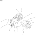
- FIG. 1 is a side view of a hydraulic excavator according to the present embodiment
- FIG. 2 is a side view of a dump truck according to the present embodiment.
- a hydraulic excavator 1 of FIG. 1 includes: a lower track structure 10; an upper swing structure 11 to be swingable provided at an upper part of the lower track structure 10; a front work implement 12 that is an articulated work arm mounted on a front side of the upper swing structure 11; a swing motor 19 that is a hydraulic motor for swinging the upper swing structure 11; an operation room 20 which is provided on the upper swing structure 11 and into which an operator ride to operate the excavator 1; a control lever 22 provided in the operation room 20 for controlling motions of actuators mounted on the hydraulic excavator 1; and a controller 21 that includes a storage device (for example, ROM or RAM), a calculation processing device (for example, CPU) and an input/output device and that controls operations of the hydraulic excavator 1.
- a storage device for example, ROM or RAM
- a calculation processing device for example, CPU
- the front work implement 12 includes: a boom 13 rotatably provided on the upper swing structure 11; an arm 14 rotatably provided at a tip of the boom 13; a bucket (attachment) 15 rotatably provided at a tip of the arm 14; a boom cylinder 16 as a hydraulic cylinder that drives the boom 13; an arm cylinder 17 as a hydraulic cylinder that drives the arm 14; and a bucket cylinder 18 as a hydraulic cylinder that drives the bucket 15.
- the boom cylinder 16, the arm cylinder 17 and the bucket cylinder 18 are individually driven by a hydraulic fluid delivered from a hydraulic pump (not illustrated) mounted on the upper swing structure 11.
- a boom angle sensor 24, an arm angle sensor 25 and a bucket angle sensor 26 are attached respectively to rotary shafts of the boom 13, the arm 14 and the bucket 15. Respective rotational angles of the boom 13, the arm 14 and the bucket 15 can be acquired from these angle sensors 24, 25 and 26.
- a swing angular velocity sensor 27 and an inclination angle sensor 28 are attached to the upper swing structure 11, and they are configured such that swing angular velocity of the upper swing structure 11 and inclination angle in the front-rear direction of the upper swing structure 11 can be acquired.
- Posture of the front work implement 12 can be specified from detection values at the angle sensors 24, 25, 26, 27 and 28.
- a boom bottom pressure sensor 29 and a boom rod pressure sensor 30, and an arm bottom pressure sensor 31 and an arm rod pressure sensor 32 are attached respectively to the boom cylinder 16 and the arm cylinder 17, such that the pressure inside each hydraulic cylinder can be acquired.
- Thrust forces of the cylinders 16 and 18, that is, driving forces given to the front work implement 12 can be specified from detection values at the pressure sensors 29, 30, 31 and 32.
- the boom angle sensor 24, the arm angle sensor 25, the bucket angle sensor 26, the inclination angle sensor 28 and the swing angular velocity sensor 27 may be replaced by other sensors insofar as the other sensors can detect physical quantities concerning the posture of the front work implement 12.
- the boom angle sensor 24, the arm angle sensor 25 and the bucket angle sensor 26 can be each replaced by an inclination angle sensor or an inertia measuring unit (IMU).
- the boom bottom pressure sensor 29, the boom rod pressure sensor 30, the arm bottom pressure sensor 31 and the arm rod pressure sensor 32 can be replaced by other sensors insofar as the other sensors can detect physical quantities concerning the thrust forces generated by the boom cylinder 16 and the arm cylinder 17, that is, the driving forces given to the front work implement 12.
- moving speeds of the boom cylinder 16 and the arm cylinder 17 may be detected by stroke sensors, or moving speeds of the boom 13 and the arm 14 may be detected by IMUs, thereby detecting the motions of the front work implement 12.
- An external input/output device 23 that displays measurement results of a load measuring system is provided inside the operation room 20, and a wireless transceiver 33 for the controller 21 to communicate with an external controller (for example, a controller 40) is attached to an upper surface of the upper swing structure 11.
- a display device 23A (see FIG. 3 ) that displays results of calculation in the controller 21 and the like, and an input device 23B (see FIG. 3 ) for an operator to input information to the controller 21.
- the display device 23A there can be utilized, for example, a liquid crystal display.
- the input device 23B there can be utilized, for example, a ten-key pad, a touch panel, a keyboard or the like.
- the dump truck 2 of FIG. 2 includes a machine body 34, four tires 35a, 35b, 35c and 35d attached individually to front and rear axles (not illustrated) provided on the machine body 34, a vessel 36 as a cargo bed into which a matter to be loaded is thrown by the hydraulic excavator 1, and an operation room 37 into which the operator rides to operate the dump truck 2.
- suspensions 38a, 38b, 38c and 38d that support the machine body 34 are attached to the axles.
- the suspensions 38a, 38b, 38c and 38d are provided with suspension pressure sensors 39a, 39b, 39c and 39d (first machine status sensors) for measuring the pressures of suspensions.
- the suspension pressure sensors 39a, 39b, 39c and 39d detects the suspension pressures as physical quantities concerning the weight of the object to be worked that is loaded into the dump truck 2.
- the controller 40 that includes a storage device (for example, ROM or RAM), a calculation processing device (for example, CPU) and an input/output device and that controls the dump truck 2, and a wireless transceiver 42 for the controller 40 to communicate with an external controller (for example, the controller 21) are attached to the machine body 34.
- a display device 41 for displaying machine body information on the dump truck 2 is provided inside the operation room 37.
- the display device 41 there can be utilized, for example, a liquid crystal display.
- the machine body 34 is provided with a machine speed sensor (third machine body status sensor) 43 that measures the traveling speed of the dump truck 2.
- suspension pressure sensors 39a, 39b, 39c and 39d can be replaced by other sensors insofar as the other sensors can detect physical quantities concerning the weight of the object to be worked loaded into the dump truck 2 by the hydraulic excavator 1.
- machine speed sensor 43 can be replaced by other sensor insofar as the other sensor can detect a physical quantity concerning the traveling status of the dump truck 2.
- FIGS. 3 and 4 are external views depicting an example of motion of the hydraulic excavator 1 during a loading work.
- the hydraulic excavator 1 of FIG. 3 is performing an "excavating motion" of excavating the object to be worked (the object to be excavated) 3 and loading the object to be worked 4 into the bucket 15, and the hydraulic excavator 1 of FIG. 4 is performing a "loading operation" of releasing the object to be worked 4 in the bucket 15 onto the cargo bed 36 of the dump truck 2.
- FIG. 5 is a system configuration diagram of a load measuring system in the present embodiment, in which respective functions are depicted in block diagrams in the inside of the controller 40 and the controller 21.
- the controller 40 on the dump truck 2 side receives inputs of signals from the suspension pressure sensors 39a, 39b, 39c and 39d and the machine speed sensor 43, and is configured such that information (for example, loading determination and loading work determination which will be described later) computed based on these signals can be transmitted to the controller 21 on the excavator side through the wireless transceiver 42.
- the controller 40 functions as: a loading determination section 52 that determines whether or not the loading of the object to be worked onto the dump truck 2 (throwing of the object to be worked onto the cargo bed 36) by the hydraulic excavator 1 has been conducted based on the weight of the object to be worked calculated from detection values outputted from the suspension pressure sensors 39a, 39b, 39c and 39d; a loading work determination section 57 that determines whether or not the dump truck 2 is under the loading work of loading the object to be worked by the hydraulic excavator 1 based on the speed of the dump truck 2 calculated by a detection value outputted by the machine speed sensor 43; and a transmission/reception section 53 that controls transmission/reception of information (for example, results of determination by the loading determination section 52 and the loading work determination section 57) through the wireless transceiver 42.
- a loading determination section 52 that determines whether or not the loading of the object to be worked onto the dump truck 2 (throwing of the object to be worked onto the cargo bed 36) by the hydraulic excavator 1 has been
- the controller 21 on the hydraulic excavator 1 side is configured to be able to receive, as inputs, outputs of the angle sensors 24 to 28 and the pressure sensors 29 to 32, reception signals of the wireless transceiver 33, and information inputted from the input device 23B, to calculate information (for example, the loading amount onto the hauling machine 2) computed based on the inputs, display the information on the display device 23A, or to transmit the information to the controller 40 on the dump truck side through the wireless transceiver 33.
- FIG. 6 is a flow chart depicting a method (sixth determination) of determining whether or not the dump truck 2 is under a loading work by the loading work determination section 57 in the controller 40 on the dump truck 2 side
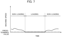
- FIG. 7 is an example of graph depicting the relation between a detection value at the machine speed sensor 43 and the result of determination by the loading work determination section 57.
- the flow chart of FIG. 6 is executed every predetermined sampling period in the controller 40 on the dump truck 2.
- the loading work determination section 57 first determines whether or not a fixed time ⁇ tv has passed from the time of start of the flow chart, in step S100. When it is determined that the fixed time ⁇ tv has not passed, the control returns to before execution of step S100, and continues monitoring time passage in step S100. On the other hand, when it is determined that the fixed time ⁇ tv has passed, the control proceeds to step S101.
- step S101 it is determined whether or not the loading work determination is in non-loading work.
- the loading work determination includes "in loading work” that indicates that the dump truck 2 is under a loading work together with the hydraulic excavator 1, and "in non-loading work” that indicates that the dump truck 2 is not under a loading work (for example, it is in traveling).
- the loading work determination is set in steps S103 and S105 described later.
- a default value (a value at the time of start of the flow of FIG. 6 ) for the loading work determination is in non-loading work.
- the control goes to step S102.
- the control goes to step S104.
- step S102 it is determined whether or not the machine speed (traveling speed) of the dump truck 2 is equal to or less than a predetermined value, based on an output from the machine speed sensor 43.
- the predetermined value here is a value by which it can be determined whether or not the dump truck 2 is at stoppage, and can be set at, for example, 1 km/h.
- the loading work determination is set in step S103 to be in loading work, after which the control goes to step S106.
- the processing in step S103 is skipped, and the control goes to step S106. As depicted in FIG.
- the dump truck 2 in a case where the machine speed is lowered to or below the predetermined value during when the loading work determination is set to be "in non-loading work," the dump truck 2 is deemed as being at stoppage for a loading work, and the loading work determination is changed to "in loading work.”
- step S104 it is determined whether or not the machine speed of the dump truck 2 is equal to or more than a predetermined value, based on an output from the machine speed sensor 43.
- the predetermined value here is the same as the predetermined value in step S102, and is a value by which it can be determined whether or not the dump truck 2 is at stoppage.
- the loading work determination is set to be in non-loading work in step S105, after which the control goes to step S106.
- the processing in step S105 is skipped, and the control goes to step S106. As depicted in FIG.
- the loading work determination section 57 outputs the result of the loading work determination of the dump truck 2 (whether the dump truck 2 is in loading work or in non-loading work) to the transmission/reception section 53 in step S106, and the transmission/reception section 53 transmits it to the hydraulic excavator 1 through the wireless transceiver 42.
- the control returned to before step S100, and the loading work determination section 57 monitors whether a predetermined time has passed from the time of finish of step S106, in step S100.
- a flow chart may be configured such that the control goes to step S103 or step S105 and the loading work determination is changed only when a machine speed satisfying a condition has continued for a predetermined time in step S102 or step S104.
- FIG. 8 is a flow chart depicting a method (second determination) of determining whether or not the loading of the object to be worked onto the dump truck 2 by the hydraulic excavator 1, by the loading determination section 52 in the controller 40 on the dump truck 2 side.
- FIG. 9 is a graph depicting an example of time variation of a detection value at the suspension pressure sensor 39a of the dump truck 2 under a loading work.
- Each step in FIG. 8 is executed every predetermined sampling period in the controller 40 of the dump truck 2.
- the loading determination section 52 first determines, in step S110, whether or not a fixed time ⁇ tp has passed from the time of start of the flow chart; when it is determined that the fixed time ⁇ tp has not passed, the control goes to before execution of step S110, and monitoring of passed time is continued in step S110. On the other hand, when it is determined that the fixed time ⁇ tp has passed, the control proceeds to step S111.
- step S111 pressure values outputted from the four suspension pressure sensors 39a to 39d are acquired.
- step S112 differences ⁇ P between the pressure values obtained in step S111 by the suspension pressure sensors 39a to 39d and preceding-time pressure values are computed, and it is determined whether or not any one of the four differences is equal to or more than a predetermined value.
- the "preceding-time pressures" here means the pressure values acquired in step S111 before one control period (before ⁇ tp) and stored in step S115.
- the predetermined value here is a value by which it can be determined whether or not the object to be worked has been thrown onto the cargo bed 36 of the dump truck 2, and can be set to, for example, a pressure value increased by the weight of the object to be worked equal to one half of the bucket capacity.
- step S112 when any one of the four differences ⁇ Pa to ⁇ Pd is equal to or more than the predetermined value, it is determined that the object to be worked has been thrown onto the cargo bed 36, and the control proceeds to step S113. If not so, the control proceeds to step S115.
- step S113 the loading determination section 52 calculates the weight (loaded amount) M (second load) of the object to be worked that is thrown in.
- inside diameters of the suspensions 38a to 38d be Aa to Ad and let the gravitational acceleration be g, then the weight M (second load) of the object to be worked is represented by the following formula (1).
- M Aa ⁇ ⁇ Pa + Ab ⁇ ⁇ Pb + Ac ⁇ ⁇ Pc + Ad ⁇ ⁇ Pd / g
- the loading determination section 52 determines (loading determination) that the loading of the object to be worked onto the dump truck 2 by the hydraulic excavator 1 has been conducted, in step S114, while the transmission/reception section 53 transmits the determination result (loading determination) and the loaded amount M to the controller 21 on the hydraulic excavator 1 side through the wireless transceiver 42, and the control proceeds to step S115.
- step S115 the loading determination section 52 stores the suspension pressures acquired in step S111 this time as the preceding-time suspension pressures for calculation in step S112 next time, and the transmission/reception section 53 transmits the suspension pressures to the controller 21 on the hydraulic excavator 1 side through the wireless transceiver 42. Thereafter, the control returns to before step S110, and the loading determination section 52 stands by until the fixed time ⁇ tp passes again.
- FIG. 10 is a flow chart depicting a method (first determination) of determining whether or not the loading of the object to be worked onto the dump truck 2 by the hydraulic excavator 1 has been conducted, by the conveyance determination section 51 in the controller 21 on the hydraulic excavator 1 side.
- FIG. 11 is an example of graph depicting the relation between a detection value at the arm bottom pressure sensor 31 (arm cylinder bottom pressure) and a detection value at the bucket angle sensor 26 (arm-bucket relative angle) and the result of determination by the conveyance determination section 51.
- the flow chart of FIG. 10 is executed every predetermined sampling period in the controller 21 of the hydraulic excavator 1.
- the conveyance determination section 51 monitors an output of the arm bottom pressure sensor 31, and determines whether or not the output has exceeded a preset threshold 1 from the state of being below the threshold 1, in step S120. Since the hydraulic excavator 1 performs excavation by pushing out the arm cylinder 17, the arm cylinder bottom pressure increases during an excavating motion, as depicted in the graph on the lower side in FIG. 11 . In the present embodiment, therefore, the excavating motion is deemed as being started at the timing when the arm bottom pressure exceeds the threshold 1. When it is determined in step S120 that the arm bottom pressure has exceeded the threshold 1 from the state of being below the threshold 1, the conveyance determination section 51 determines that the hydraulic excavator 1 has started an excavating motion, and the control proceeds to step S121. In contrast, when the arm bottom pressure does not exceed the threshold 1 from the state of being below the threshold 1 (when it remains equal to or less than the threshold 1), the control returns to before step S120, and monitoring of the output of the arm bottom pressure sensor 31 is continued.
- step S121 continued monitoring of the output of the arm bottom pressure sensor 31 is conducted, and it is determined whether or not the output has decreased below a preset threshold 2 from the state of being above the threshold 2. Since the arm cylinder bottom pressure decreases when an excavating motion is finished as depicted in the graph on the lower side in FIG. 11 , in the present embodiment the excavating motion is deemed as finished and the conveying motion is deemed as started, at the timing when the arm bottom pressure decreases below the threshold 2.
- the conveyance determination section 51 determines that the hydraulic excavator 1 has finished the excavating motion and that the conveying motion is started (fourth determination (No.
- step S122 the conveyance determination section 51 determines that the excavating motion is being continued, and the control returns to before step S121, to continue monitoring the output of the arm bottom pressure sensor 31.
- the relation between the threshold 1 and the threshold 2 is established in the example depicted in FIG. 11 , but this is merely an example.
- Arbitrary threshold values can be set in such a range that the start and finish of an excavating motion of the hydraulic excavator 1 can be determined.
- the relation in magnitude between the threshold 1 and the threshold 2 does not matter.
- step S122 the conveyance determination section 51 outputs to the exterior a determination that a conveying motion has been started, and the control proceeds to step S123.
- the destinations to which this determination is outputted include the load integration propriety determination section 55.
- step S123 the conveyance determination section 51 monitors an output of the bucket angle sensor 26, and determines whether or not an arm-bucket relative angle (the angle formed between the arm 14 and the bucket 15) has exceeded a preset threshold 3.
- the hydraulic excavator 1 having finished the conveying motion and starting the loading operation operates such as to widen the angle formed between the arm 14 and the bucket 15 in order to release the earth and sand (the object to be excavated) in the bucket 15. Specifically, as depicted in the graph on the upper side in FIG. 11 , the relative angle between the arm 14 and the bucket 15 increases at the time of transition from the conveying motion to the loading operation.
- the conveying motion is deemed as finished and the loading operation is deemed as started at the timing when the relative angle between the arm 14 and the bucket 15 exceeds the threshold 3.
- the conveyance determination section 51 determines that the hydraulic excavator 1 has finished the conveying motion and has started the loading operation (fourth determination (No. 2)), and the control proceeds to step S124.
- the conveyance determination section 51 determines that the conveying motion is being continued, and the control returns to before step S123, to continue monitoring the output of the bucket angle sensor 26.
- step S124 the conveyance determination section 51 outputs to the exterior a determination that the conveying motion has been finished (a determination that the loading operation has been started), and the control returns to step S120.
- the destinations to which this determination is outputted include the load integration propriety determination section 55 and the abnormality determination section 58.
- FIG. 12 is a flow chart depicting a method (fifth determination) of determining presence or absence of an abnormality in the load measuring system according to the present embodiment, by the abnormality determination section 58 in the controller 21 on the hydraulic excavator 1 side.
- the flow chart of FIG. 12 is executed every predetermined sampling period in the controller 21 of the hydraulic excavator 1.
- step S130 the abnormality determination section 58 determines whether or not the loading work determination (the result of the loading work determination transmitted in step S106 of FIG. 6 ) received from the dump truck 2 is set to the loading work.
- the control proceeds to step S133, whereas when the loading work determination is set to "non-loading work,” the control proceeds to step S131.
- the abnormality determination section 58 determines whether or not a predetermined time ⁇ tw has passed from the time of start of the flow chart, and checks if a state of no reception of the result of the loading work determination is being continued.
- the predetermined time ⁇ tw here is a time of equal to or more than the execution period of the flow chart of FIG. 6 by the loading work determination section 57, that is, a time of equal to or more than the fixed time ⁇ tv in step S100 of FIG. 6 .
- the value of ⁇ tw is preferably a value in the range from ⁇ tv to two times ⁇ tv.
- the controller 40 of the dump truck 2 transmits the result of the loading work determination at the fixed period ⁇ tv, as depicted in FIG.
- step S131 If reception of the result of the loading work determination is absent even when the fixed period ⁇ tv has passed, therefore, communication with the controller 40 of the dump truck 2 may not be being performed.
- step S131 the control returns to before step S130, and the presence or absence of reception of the loading work determination is again monitored in step S130.
- step S132 the control proceeds to step S132.
- step S132 it is determined whether or not it has been determined in the conveyance determination section 51 that the hydraulic excavator 1 has finished the conveying motion.
- the control returns to before step S130, and whether there is reception of the result of the loading work determination is again monitored in step S130.
- the control proceeds to step S137, where it is determined that an abnormality is present in the system and an abnormality determination is outputted.
- step S132 in a case where the result of loading work determination could not been received for the predetermined period ⁇ tw in step S131 and where it is determined in step S132 that the hydraulic excavator 1 has finished conveyance, it can be decided that the hydraulic excavator 1 is conducting loading onto the dump truck 2 but communication is not established between them. In other words, when determination at step S132 is YES, it can be decided that an abnormality in communication relation is present. Note that start of a loading operation may be determined in step S132 in place of finish of the conveying motion.
- step S133 whether or not there is an abnormality in the output values of the suspension pressure sensors 39a to 39d transmitted from the controller 40 of the dump truck 2 in step S115 of FIG. 8 is determined in step S133 (fifth determination). Specifically, from the output values of the suspension pressure sensors 39a to 39d indicative of the weight of the object to be worked loaded on the dump truck 2, an average value of the pressure values of the four suspensions is computed, then differences of the four pressure values from the average value are computed, and, if all the four differences are within a predetermined value, it is deemed that no abnormality is present in the suspension pressure sensors 39a to 39d, and the control proceeds to step S134.
- any one of the four differences is equal to or more than a predetermined value, it is determined that an abnormality is present in the system.
- the pressure value is not outputted normally, and the difference between the output value of the troubled sensor and that of the non-troubled sensor is enlarged. Therefore, in a case where determination at step S133 is NO, it can be decided that one or some of the pressure sensors 39a to 39d may be troubled.
- step S134 the abnormality determination section 58 determines whether or not a determination that the loading of the object to be worked onto the dump truck 2 by the hydraulic excavator 1 has been conducted (the loading determination transmitted in step S114 of FIG. 8 ) has been received from the controller 40 of the dump truck 2.
- the control proceeds to step S135, and, if not so, the control returns to before step S130, to again monitor whether or not the loading determination has been received.
- step S135 a load value (first load) of the object to be worked in the bucket 15 outputted from the load calculation section 50 in step S146 of FIG. 14 to be described later and a loaded amount M (second load) outputted from the loading determination section 52 in step S114 of FIG. 8 are compared with each other, and it is determined whether or not the difference (weight difference) between them is within a predetermined value.
- the weight difference is within the predetermined value, it is determined in step S136 that the system is normal.
- step S137 determines the predetermined value.
- decision at step S135 is NO, it can be decided that a trouble may have been generated in either of the load calculation section 50 of the hydraulic excavator 1 and the loading determination section 52 of the dump truck 2.
- the determination result of the system abnormality based on the flow chart of FIG. 12 is stored inside the controller 21 on the hydraulic excavator 1 side, and is referred to, as required, by the controller 21 itself or other devices or computers. Even in a case where abnormality determination is once made in step S137, if the control proceeds to step S136 due to a change-over of the dump truck 2 or the like, a determination result that the system is normal is stored.
- FIG. 13 is an illustration of a calculating method for an instantaneous load Ml of the object to be worked in the bucket 15 by the load calculation section 50 in the controller 21 on the hydraulic excavator 1 side.
- the load is computed by utilizing the balance between a torque acting around a rotational axis of the boom 13 which torque is generated by the boom cylinder 16, a torque generated by the front work implement 12 due to gravity and a swing centrifugal force, and a torque generated by the object to be worked due to gravity and a swing centrifugal force.
- a thrust force Fcyl of the boom cylinder 16 is computed by multiplying an output signal of the boom bottom pressure sensor 29 and an output signal of the boom rod pressure sensor 30 by a pressure receiving area of the boom cylinder 16, and then obtaining the difference between the products.
- a torque Tbm generated by the boom cylinder 16 is computed from the following formula (2), where Lbm is the length of a line segment interconnecting a boom rotational axis and a working point of the thrust force Fcyl of the boom cylinder 16, and ⁇ bmcyl is an angle formed between the thrust force Fcyl of the boom cylinder 16 and the line segment Lbm and the direction of the thrust force.
- Tbm Fcyl ⁇ Lbm ⁇ sin ⁇ bmcyl
- a torque Tgfr generated by the front work implement 12 due to gravity is computed by the following formula (3), where Mfr is the center-of-gravity weight of the front work implement 12, g is the gravitational acceleration, and Lfr is the length in the front-rear direction from the rotational axis of the boom to the center of gravity of the front work implement.
- Tgfr Mfr ⁇ g ⁇ Lfr
- a torque Tcfr generated by the front work implement 12 due to a swing centrifugal force is computed by the following formula (4), where ⁇ is the swing angular velocity, and ⁇ fr is the angle formed between a line segment interconnecting the boom rotational axis and the center of gravity of the front work implement and a horizontal plane.
- Tcfr Mfr ⁇ Lfr ⁇ ⁇ 2 ⁇ sin ⁇ fr
- Mfr, Lfr, and ⁇ fr are computed from the respective center-of-gravity positions and weights of the boom 13, the arm 14 and the bucket 15 that are preset and the angle signals outputted from the boom angle sensor 24, the arm angle sensor 25, the bucket angle sensor 26 and the inclination angle sensor 28.
- a torque Tgl generated by the object to be worked due to gravity is computed by the following formula (5), where Ml is the instantaneous load of the object to be worked, and Ll is the length in the front-rear direction from the rotational axis of the boom to the center of gravity of the bucket.
- Tgl Ml ⁇ g ⁇ Ll
- a torque Tcl generated by the object to be worked due to the swing centrifugal force is computed by the following formula (6), where ⁇ l is the angle formed between a line segment interconnecting the rotational axis of the boom and the center of gravity of the object to be worked and a horizontal plane.
- Tcl Ml ⁇ Ll ⁇ ⁇ 2 ⁇ sin ⁇ l
- the instantaneous load Ml is computed by the following formula (7).
- Ml Tbm ⁇ Tgfr ⁇ Tcfr / Ll ⁇ g + ⁇ 2 ⁇ sin ⁇ l
- the calculations of the load by the formulas (2) to (8) cannot always output a fixed value during conveyance due to the sensor noises and the characteristics of the hydraulic circuit; therefore, the instantaneous load Ml computed in a predetermined period during when the hydraulic excavator 1 is in a conveying motion is averaged, and the load (first load) of the object to be worked is determined.
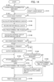
- FIG. 14 is a flow chart of processing steps performed by the load calculation section 50, the load integration propriety determination section 55 and the load integration section 56 in the controller 21 on the hydraulic excavator 1 side.
- the load calculation section 50 determines the load (first load) of the object to be worked in the bucket during conveyance
- the load integration propriety determination section 55 determines whether or not the load (first load) is to be integrated (third determination)
- the load integration section 56 integrates the load and thereby outputs the loaded weight.
- the flow chart of FIG. 14 is executed every predetermined sampling period in the controller 21 on the hydraulic excavator 1 side.
- step S140 the load integration section 56 determines whether or not the setting of loading work determination outputted at a fixed period ⁇ tv from the dump truck 2 in step S106 of FIG. 6 has been changed over.
- the control proceeds to step S142, whereas when it is determined that the loading work determination has been changed over, the control proceeds to step S141 to reset the loaded weight on the dump truck 2, and the control proceeds to step S142.
- the loaded weight is reset at with the timing when in loading work and in non-loading work are changed over, whereby it is possible to integrate the load of the object to be worked only in the period in which the dump truck 2 is under a loading work.
- step S142 the load calculation section 50 monitors whether or not a conveying motion start determination has been outputted from the conveyance determination section 51.
- the control proceeds to step S143, and if not so, the control returns to before step S140, to monitor the output of the loading work determination section 57 (setting of the loading work determination).
- step S143 the load calculation section 50 performs calculations concerning the formulas (2) to (8) to calculate the instantaneous load Ml of the object to be worked, the instantaneous load Ml is recorded in the controller 21 in step S144, and the control proceeds to step S145.
- step S145 the load calculation section 50 determines whether or not a predetermined time has passed from the time of output of the conveying motion start determination (the time when determination of YES is made in step S142). When it is determined here that the predetermined time has not passed, the control returns to before step S143, and step S143 and step S144 are again executed. By repeating step S143 and step S144 in the predetermined time, a plurality of instantaneous loads Ml calculated in the predetermined time can be recorded. On the other hand, when it is determined that the predetermined time has passed, the control proceeds to step S146.
- step S146 the load calculation section 50 calculates an average load of the plurality of instantaneous loads Ml recorded within the predetermined time, the average load is made to be a load value (first load) of the object to be worked, and the control proceeds to step S147.
- step S147 the load integration propriety determination section 55 monitors whether or not a conveying motion finish determination has been outputted from the conveyance determination section 51. When it is determined that the conveying motion finish determination has not been outputted, the control returns to before step S147, to continue monitoring the conveying motion finish determination. On the other hand, when it is determined that the conveying motion finish determination has been outputted, a loading operation by the hydraulic excavator 1 is deemed as started, and the control proceeds to step S148. Note that in step S147, a loading operation start determination may be monitored in place of the conveying motion finish determination.
- step S148 the load integration propriety determination section 55 determines whether or not the abnormality determination section 58 has made an abnormality determination. Specifically, determination is made by referring to the result of abnormality determination stored in the inside of the controller 21.
- the control proceeds to step S149, whereas when the abnormality determination has been made (that is, when the abnormality determination is stored), the control proceeds to step S151.
- step S149 the load integration propriety determination section 55 determines whether or not a determination that the loading of the object to be worked onto the dump truck 2 by the hydraulic excavator 1 has been conducted (a loading determination transmitted in step S114 of FIG. 8 ) has been received from the controller 40 of the dump truck 2.
- the load integration section 56 integrates the average load computed in step S145 onto the loaded weight (integrated weight) in step S154, and the control proceeds to step S155.
- the control proceeds to step S150.
- step S150 the load integration propriety determination section 55 determines whether or not a predetermined time ⁇ T has passed from the time of conveying motion finish determination in step S147.
- the predetermined time ⁇ T there can be set an arbitrary time within a range from (1) a time required for the hydraulic excavator 1 to perform a loading operation to (2) a time required for the hydraulic excavator 1 to perform a series of operations including excavation, conveyance, loading and reaching at the time of a loading work.
- the predetermined time ⁇ T may be inputted and determined by the operator through the input device 23B according to the tendency of the required time of each operator concerning the loading work.
- step S150 When it is determined in step S150 that the predetermined time ⁇ T has not passed, the control returns to before step S148, to again monitor the abnormality determination and the loading determination.
- step S150 when it is determined that the predetermined time ⁇ T has passed, it is deemed that the hydraulic excavator 1 has completed a conveying motion (has started a loading operation) but the loading of the object to be worked onto the cargo bed 36 of the dump truck 2 has not been performed, and the control proceeds to step S155 by skipping step S154 (that is, without integration of the average load in step S145).
- step S150 A specific example of a case where the control proceeds from step S150 to step S155 is a situation in which the hydraulic excavator 1 puts the bucket 15 into a dump operation, but, since the cargo bed 36 of the dump truck 2 is not located thereunder, the loading of the object to be worked onto the dump truck 2 is failed.
- the load integration propriety determination section 55 instructs outputting, to the display device 23A, of a warning display of notifying the operator that automatic load integration is impossible due to system abnormality, and an inquiry display of inquiring the operator if integration is needed, in step S151, whereby the warning display and the inquiry display are displayed on the display device 23A (for the inquiry display, refer to an inquiry display section 81 of FIG. 15 to be described later).
- the operator desires to perform integration, in response to the warning display and the inquiry display, an instruction of need for integration is inputted through the input device 23B.
- step S152 the load integration propriety determination section 55 determines whether or not the instruction of need for integration (this may herein be referred to as "integration instruction") has been inputted by the operator through the input device 23B.
- integration instruction the instruction of need for integration
- the load integration section 56 integrates (step S154) the average load computed in step S145 onto the previous loaded weight (integrated load), and the control proceeds to step S155.
- step S153 the control proceeds to step S153, to determine whether or not a predetermined time has passed from the warning output in step S151.
- step S153 When it is determined in step S153 that the predetermined time has not passed, the control returns to before step S152, to again monitor the presence or absence of an input of the integration instruction. On the other hand, when it is determined that the predetermined time has passed, the control proceeds to step S155 by skipping step S154.
- step S155 the load calculation section 50 resets the average load calculated in step S146, and the control returns to before step S140.
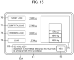
- FIG. 15 is an external view of a display screen (output screen) of the display device 23A.
- a displaying method for load measurement results in the load measuring system according to the present embodiment and a method of instructing execution of integration in a case where an abnormality is present in the system will be described.
- the display device 23A is configured by a touch panel.
- the display screen of the display device 23A includes: a target load display section 70 where to display a target loaded weight (target load value) on the dump truck 2; an in-bucket load display section 72 where to display the load value (average load value of the instantaneous load Ml) of the object to be worked in the bucket 15 that is calculated in step S146 of FIG.
- a sum total load display section 71 where to display the integrated value of load value of the object to be worked in the bucket 15 that is calculated in step S154 (integrated load on the dump truck 2); a remainder load display section 72 where to display the difference between the value (target loaded weight) displayed in the target load display section 70 and the value (integrated value of load value) displayed in the sum total load display section 71; an integration bar display section 75 where to display the history of the load value of the object to be worked that is integrated in numerical values and a pile-up vertical bar graph (integration bar); and an inquiry display section 81 where to display an inquiry display (a display of inquiring of the operator whether integration is needed) in step S151.
- the value in the in-bucket load display section 72 is updated to a newest value calculated in step S146 of FIG. 14 , and is updated to 0 when reset in step S155.
- the value in the sum total load display section 71 and the display in the integration bar display section 75 are updated to a newest value when step S154 is executed, and are updated to 0 when reset in step S141.
- An inquiry display 83 of inquiring of the operator whether or not loading is needed in step S151 when a system abnormality is detected is displayed in the inquiry display section 81.
- An integration instruction input section 82 as a button to be depressed in the case where the operator desires integration is displayed in the inquiry display section 81 together with the inquiry display 83.
- the load integration propriety determination section 55 determines that an integration instruction has been inputted in step S152.
- the integration instruction input section 82 is not depressed, the integration in step S154 is not executed. Note that in the example of FIG. 15 , a configuration is adopted in which a remaining time (5 seconds in FIG.
- step S151 from the timing of outputting of the warning display in step S151 until the predetermined time has passed in step S153 is displayed in the inquiry display section 81 together with the inquiry display 83, and, when the remaining time is reduced to zero (that is, when the predetermined time in step S153 has been passed), the display in the inquiry display section 81 disappears.
- the loading work determination section 57 in the controller 40 changes the loading work determination from in non-loading work to in loading work ( FIG. 6 : steps S102 and S103), and transmits this result to the controller 21 of the hydraulic excavator 1 ( FIG. 6 : step S106).
- the controller 21 of the hydraulic excavator 1 having received the loading work determination result recognizes the change-over of the loading work determination result and resets the loaded weight ( FIG. 14 : steps S140 and S141), and starts monitoring whether or not the hydraulic excavator 1 starts a conveying motion ( FIG. 14 : step S142).
- the bottom pressure of the arm cylinder 17 exceeds threshold 1 due to load attendant on excavation, thereafter, when the excavating motion is finished and the load is lightened, the bottom pressure of the arm cylinder 17 decreased below threshold 2.
- the conveyance determination section 51 of the controller 21 outputs a determination indicative of that the hydraulic excavator 1 has started the conveying motion ( FIG. 10 : step S122).
- the load integration section 56 in the controller 21 repeatedly calculates and records the instantaneous load Ml of the object to be worked in the bucket 15 in a predetermined time, and causes an average load value of the instantaneous loads Ml calculated in the predetermined time to be a load value of the object to be worked ( FIG. 14 : steps S143 to S146). In other words, the computation of the load value of the object to be worked is conducted during the conveying motion of the hydraulic excavator 1.
- the hydraulic excavator 1 having moved the bucket 15 to the upper side of the cargo bed of the dump truck 2 by the conveying motion starts a dumping operation of the bucket 15 for starting a loading operation.
- the arm-bucket relative angle exceeds threshold 3
- the conveyance determination section 51 in the controller 21 outputs a determination indicating that the hydraulic excavator 1 has finished the conveying motion ( FIG. 10 : step S124). That the conveying motion finish determination is outputted from the conveyance determination section 51 in this way indicates that the hydraulic excavator 1 has started the loading operation, and indicates the object to be worked is soon going to be thrown onto the cargo bed 36 of the dump truck 2 by the hydraulic excavator 1.
- the controller 21 of the hydraulic excavator 1 starts monitoring whether or not loading determination is inputted from the controller 40 of the dump truck 2, with the output of conveying motion finish determination from the conveyance determination section 51 as a trigger ( FIG. 14 : step S149).
- the dump truck 2 normally receives the loading of the object to be worked from the hydraulic excavator 1 by the loading operation of the hydraulic excavator 1, the pressures of the suspensions 38a to 38d of the dump truck 2 increase due to the load, and, as a result, the controller 40 transmits the loading determination to the controller 21 of the hydraulic excavator 1 ( FIG. 8 : step S114).
- the controller 21 Upon confirmation of the reception of the loading determination from the dump truck 2, the controller 21 computes the loaded weight on the dump truck 2 by integrating the average load value of the instantaneous loads Ml previously calculated.
- the loaded weight at the time of first-time loading is an average load value.
- the computation result of the loaded weight is displayed in the sum total load display section 71 of the display device 23A of the hydraulic excavator 1 ( FIG. 15 ).
- the same processing as above is repeated when the loading from the hydraulic excavator 1 onto the dump truck 2 is normally performed, and the load value of the object to be worked that is computed by the load calculation section 50 is integrated to the loaded weight.
- the loading determination is not transmitted from the controller 40 of the dump truck 2 even when the predetermined time ⁇ T is passed from the conveying motion finish determination from the conveyance determination section 51.
- the controller 21 of the hydraulic excavator 1 deems that the hydraulic excavator 1 has conducted the loading operation but the loading onto the dump truck 2 has been failed for some reason, cancels the integration of the load value of the object to be worked attendant on the this-time loading operation, resets the load value of the object to be worked calculated during the conveying motion, and waits for an output of the next conveying motion start determination.
- abnormality determination section 58 When the result of determination by the controller 21 (abnormality determination section 58) of the hydraulic excavator 1 is abnormality determination, there is a possibility of an abnormality of communication between the two controllers 21 and 40, an abnormality of the suspension pressure sensor 39 of the dump truck 2, or an abnormality of calculation of the load value. In this case, automatic integration of the load value of the object to be worked in the same manner as in the case of normality determination is impossible, and, therefore, a warning display and the inquiry display 83 are outputted to the display device 23A ( FIG. 14 : step S151). As a result, the operator of the hydraulic excavator 1 can be made to recognize that an abnormality has been generated in the system and automatic computation of an integrated value of the load value of the object to be worked is impossible.
- the integration instruction input section 82 is displayed on the display device 23A together with the inquiry display 83.
- the operator of the hydraulic excavator 1 inputs an integration instruction to the controller 21 through the integration instruction input section 82.
- the controller 21 computes the loaded weight on the dump truck 2 by integrating the average load value of the instantaneous load Ml previously calculated, in the same manner as in the case of normality determination. As a result, the loaded weight can be computed, even in the case where an abnormality in communication between the two controllers 21 and 40 or an abnormality in the suspension pressure sensor 39 of the dump truck 2 has occurred.
- the controller 40 (loading determination section 52) of the dump truck 2 and the controller 21 (conveyance determination section 51) of the hydraulic excavator 1 each determine whether or not the loading from the hydraulic excavator 1 onto the dump truck 2 has been conducted, the controller 21 (load integration propriety determination section 55) of the hydraulic excavator 1 determines the integration propriety of the load value of the object to be worked in the bucket, based on the results of determination by both of the controllers, and, based on the result of this determination, the controller 21 (load integration section 56) of the hydraulic excavator 1 integrates the load value.
- the controller 21 of the hydraulic excavator 1 deems that the hydraulic excavator 1 has conducted a loading operation but the loading onto the dump truck 2 has been failed for some reason, then cancels the integration of the load value of the object to be worked attendant on the loading operation, and waits for the next conveying motion of the hydraulic excavator 1 and the attendant load value calculation and loading operation. Therefore, even when the loading onto the dump truck 2 is failed, the load value integrating processing can be continued without inputting the failure into the controller 21 by the operator of the hydraulic excavator 1 or other person.
- the inquiry display 83 is displayed on the display device 23A, whereby integration of the load value is manually instructed only in the case of system abnormality, and, therefore, the operational burden on the operator concerning the integration of the load value can be mitigated at normal time.
- such a configuration makes it possible to continue integration of the load value even in the case where an abnormality has been generated.
- the present invention is not limited to the above-described embodiment, and includes various modifications made without departing from the scope of the invention as defined by the claims.
- the present invention is not limited to the configuration that includes all the components described in the above embodiment, and includes configurations in which part of the components is eliminated.
- part of the components according to an embodiment may be added to or replaced by components according to another embodiment.
- FIGS. 16 and 17 are illustrations of a system that performs a determining method for the loading work of the dump truck 2, different from that of the above-described embodiment.
- FIG. 16 depicts a system configuration of the load measuring system
- FIG. 17 is an illustration of the determining method for the loading work of the dump truck 2 by the system of FIG. 16 .
- the dump truck 2 includes a GPS antenna 38, the controller 40 thereof is provided therein with a hauling machine position calculation section 66 that calculates an absolute position of the dump truck 2 based on an input signal from the GPS antenna 38, and the position of the hauling machine itself computed by the hauling machine position calculation section 66 is transmitted to the controller 21 of the hydraulic excavator 1.
- the hydraulic excavator 1 includes a GPS antenna 38, the controller 21 thereof is provided therein with a loading machine position calculation section 65 that calculates an absolute position of the hydraulic excavator 1 based on an input signal from the GPS antenna 38, and a loading work determination section 57 that determines a loading work status of the dump truck 2 based on the position information (relative distance) concerning the hydraulic excavator 1 and the dump truck 2 inputted from the loading machine position calculation section 65 and the hauling machine position calculation section 66.
- the loading work determination section 57 sets the loading work determination to in loading work.
- the loading work determination section 57 sets the loading work determination to in non-loading work.
- step S150 when determination in step S150 is YES, the control may proceed to step S151 in place of step S155.
- the processing steps subsequent to step S151 in this case is as depicted in FIG. 14 .
- step S150 it is considered that the loading onto the dump truck 2 has been failed.
- a warning display and an inquiry display are made on the display device 23A, thereby prompting the operator to input an integration instruction after again performing loading by the hydraulic excavator 1.
- Such a configuration ensures that the operator can be made to recognize that the integration is being interrupted due to failure in loading, and a state in which automatic integration is possible before failure in loading can be restored with the integration instruction as a trigger.
- step S151 of FIG. 14 upon abnormality determination the warning display and the inquiry display 83 are performed on the display device 23A independently of the cause of the abnormality determination, as described in the present embodiment; however, when abnormality is present in load computation by the controller 21 or the controller 40 (specifically, when determination in step S135 of FIG. 12 is NO), an error may exist in the load value of the object to be worked. Therefore, the system may be configured such as not to perform the inquiry display 83 but to perform only the abnormality display in this case, thereby preventing an erroneous load value from being integrated due to an operator's integration instruction.
- abnormality determination section 58 is provided in the controller 21 on the hydraulic excavator 1 side in the above-described embodiment, this may be omitted. In the case where the abnormality determination section 58 is omitted, it is sufficient to configure the control system such as to proceed to step S149 when determination in step S148 in the flow chart of FIG. 14 is YES, and to return to step S149 when determination in step S150 is NO.
- the configuration of the load measuring system of the present invention is not limited to the one depicted in FIG. 5.
- the loading determination section 52 may not necessarily be mounted in the controller 40 of the dump truck 2, and the controller 40 may be configured such that signals from the suspension pressure sensors 39a to 39d are inputted to the transmission/reception section 53, and may be transmitted from the wireless transceiver 42 directly to the hydraulic excavator 1, whereby the processing corresponding to the calculation processing performed by the loading determination section 52 is executed by the controller 21 of the hydraulic excavator 1.
- the calculation of the instantaneous load Ml is not limited to the model depicted in FIG. 13 , but may be conducted using different formulas than those described above.
- the instantaneous load may be calculated using an equation of motion of the front work implement 12 including the boom 13, the arm 14 and the bucket 15.
- the computing method for the load value of the object to be worked is not limited to the technique depicted in FIG. 14 .
- the period for averaging the load may be determined using the magnitude of the swing angular velocity and the position of the bucket 15.
- the loading determination concerning the dump truck 2 is not limited to the contents depicted in FIGS. 8 and 9 .
- a configuration may be adopted in which an acceleration sensor is attached to the vessel 36 or the machine body, a variation in the acceleration in the vertical direction generated due to throwing of the object to be worked into the vessel 36 is detected by the acceleration sensor, and the loading determination is outputted.
- the contents of display on the display device 23A are not limited to those depicted in FIG. 15 .
- the proportion of the integrated load based on the dump truck capacity may be displayed in percent, and a part where to display a history of loaded amounts (loaded weights) in the past in an aligned manner may be provided on the display screen.
- Components of the controller 40 and the controller 21 as well as the functions of and processing steps executed by the components, etc. may be partly or entirely realized by hardware (for example, designing the logics for executing the functions in the form of integrated circuit).
- the components concerning the controllers 40 and 21 may be provided in the form of programs (software) to be read and executed by a calculation processing device (e.g., CPU) for implementing the functions concerning the components of the controllers 40 and 21.
- Information concerning the programs can be stored in, for example, semiconductor memory (flash memory, SSD, etc.), magnetic recording device (hard disk drive, etc.) and recording medium (magnetic disk, optical disk, etc.).
Landscapes
- Engineering & Computer Science (AREA)
- Mining & Mineral Resources (AREA)
- Civil Engineering (AREA)
- General Engineering & Computer Science (AREA)
- Structural Engineering (AREA)
- Physics & Mathematics (AREA)
- General Physics & Mathematics (AREA)
- Mechanical Engineering (AREA)
- Operation Control Of Excavators (AREA)
- Component Parts Of Construction Machinery (AREA)
Claims (6)
- Excavateur hydraulique (1) comprenant :un vérin hydraulique entraîné par un fluide hydraulique distribué depuis une pompe hydraulique ;des instruments de travail incluant un godet (15) entraînés par le vérin hydraulique ; etun contrôleur côté excavateur hydraulique (21) calculant un poids chargé d'un objet de travail chargé jusque sur une machine de transport par l'instrument de travail,caractérisé en ce quele contrôleur côté excavateur hydraulique (21)effectue une première détermination consistant à déterminer si oui ou non le travail de chargement de l'objet jusque sur la machine de transport a été exécuté par l'excavateur hydraulique (1), la première détermination étant effectuée sur la base d'une posture de l'instrument de travail,calcule une première charge de l'objet dans le godet (15) sur la base d'une force de poussée du vérin hydraulique et d'un résultat de détermination de la première détermination,reçoit une seconde détermination consistant à déterminer si oui ou non la charge devant être ajoutée à la charge totale de la machine de transport a été exécutée par l'excavateur hydraulique (1), la seconde détermination étant transmise depuis un contrôleur côté machine de transport (40) inclus dans la machine de transport, etcalcule le poids chargé sur la machine de transport en intégrant la première charge sur la base de la seconde détermination reçue depuis le contrôleur côté machine de transport (40) et de la première détermination déterminée par le contrôleur côté excavateur hydraulique (21).
- Excavateur hydraulique (1) selon la revendication 1,
dans lequel le contrôleur côté excavateur hydraulique (21) intègre la première charge dans un cas dans lequel la seconde détermination a été reçue depuis le contrôleur côté machine de transport (40), la seconde détermination reçue détermine que le travail de chargement de objet de travail jusque sur la machine de transport a été exécuté à l'intérieur d'une durée prédéterminée à partir d'un moment où la première détermination détermine que le travail de chargement de l'objet jusque sur la machine de transport a été exécuté. - Excavateur hydraulique (1) selon la revendication 1,dans lequel le contrôleur côté excavateur hydraulique (21)détermine un début et une fin d'un déplacement de convoyage de l'excavateur hydraulique (1) pour la machine de transport sur la base de la posture de l'instrument de travail,calcule la première charge sur la base de la force de poussée du vérin hydraulique pendant une période allant du début à la fin du déplacement de convoyage, etintègre la première charge dans un cas où il est déterminé que le déplacement par convoyage a été fini et où un résultat de détermination via la seconde détermination selon laquelle le chargement de l'objet de travail jusque sur la machine de transport par l'excavateur hydraulique (1) a été exécuté est reçu depuis le contrôleur côté machine de transport (40).
- Excavateur hydraulique (1) selon la revendication 1, comprenant en outre :un dispositif d'entrée (23B) destiné à entrer une instruction provenant d'un opérateur ; etun dispositif d'affichage (23A) destiné à afficher des informations prédéterminées,dans lequel le contrôleur côté excavateur hydraulique (21)détermine une présence ou une absence d'une anomalie dans la machine de transport sur la base du poids de l'objet de travail chargé jusque sur la machine de transport, qui est transmise depuis le contrôleur côté machine de transport (40), etnotifie une génération de l'anomalie via le dispositif d'affichage (23A) dans un cas où il est déterminé qu'une anomalie est présente dans la machine de transport, et intègre la première charge dans un cas où il est entré via le dispositif d'entrée que le chargement de l'objet de travail jusque sur la machine de transport a été exécuté.
- Excavateur hydraulique (1) selon la revendication 1, comprenant en outre :un dispositif d'entrée (23B) destiné à entrer une instruction provenant d'un opérateur ; etun dispositif d'affichage (23) destiné à afficher des informations prédéterminées,dans lequel le contrôleur côté excavateur hydraulique (21)détermine qu'une anomalie est présente dans l'un ou l'autre de l'excavateur hydraulique (1) et de la machine de transport dans un cas où une différence entre une seconde charge qui est une charge de l'objet de travail chargé jusque sur la machine de transport par l'excavateur hydraulique (1) qui est calculée par le contrôleur côté machine de transport (40) et la première charge dépasse une valeur prédéterminée, etnotifie une génération de l'anomalie via le dispositif d'affichage (23A) dans un cas où il est déterminé qu'une anomalie est présente dans l'une ou l'autre de l'excavateur hydraulique (1) et de la machine de convoyage, et intègre la première charge dans un cas où il est entré via le dispositif d'entrée (23B) que le chargement de l'objet de travail jusque sur la machine de transport a été exécuté.
- Excavateur hydraulique (1) selon la revendication 1, dans lequelle contrôleur côté excavateur hydraulique (21)détermine si oui ou non la machine de transport est soumise au travail de chargement de l'objet de travail par l'excavateur hydraulique (1) sur la base d'une vitesse de déplacement de la machine de transport, la vitesse de déplacement étant transmise depuis la machine de transport, et réinitialise une valeur intégrée de la charge de l'objet de travail dans un cas où un résultat de la détermination selon laquelle la machine de transport est oui ou non soumise au travail de chargement de l'objet de travail par l'excavateur hydraulique (1) sur la base d'une vitesse de déplacement de la machine de transport, est modifié.
Applications Claiming Priority (2)
| Application Number | Priority Date | Filing Date | Title |
|---|---|---|---|
| JP2017181789A JP6745254B2 (ja) | 2017-09-21 | 2017-09-21 | 油圧ショベル |
| PCT/JP2018/035212 WO2019059383A1 (fr) | 2017-09-21 | 2018-09-21 | Pelle hydrauliquze |
Publications (3)
| Publication Number | Publication Date |
|---|---|
| EP3686357A1 EP3686357A1 (fr) | 2020-07-29 |
| EP3686357A4 EP3686357A4 (fr) | 2021-06-30 |
| EP3686357B1 true EP3686357B1 (fr) | 2025-04-23 |
Family
ID=65811383
Family Applications (1)
| Application Number | Title | Priority Date | Filing Date |
|---|---|---|---|
| EP18858189.6A Active EP3686357B1 (fr) | 2017-09-21 | 2018-09-21 | Pelle hydraulique |
Country Status (6)
| Country | Link |
|---|---|
| US (1) | US11454005B2 (fr) |
| EP (1) | EP3686357B1 (fr) |
| JP (1) | JP6745254B2 (fr) |
| KR (1) | KR102234963B1 (fr) |
| CN (1) | CN110382789B (fr) |
| WO (1) | WO2019059383A1 (fr) |
Cited By (1)
| Publication number | Priority date | Publication date | Assignee | Title |
|---|---|---|---|---|
| US12618226B2 (en) | 2021-03-29 | 2026-05-05 | Sumitomo Construction Machinery Co., Ltd. | Display device for shovel, shovel, and assist device for shovel |
Families Citing this family (11)
| Publication number | Priority date | Publication date | Assignee | Title |
|---|---|---|---|---|
| US11125605B2 (en) * | 2017-03-03 | 2021-09-21 | Cnh Industrial America Llc | System and method for estimating implement load weights for a work vehicle |
| JP6868938B2 (ja) * | 2017-08-24 | 2021-05-12 | 日立建機株式会社 | 建設機械の荷重計測システム |
| US11498785B2 (en) * | 2019-01-30 | 2022-11-15 | Caterpillar Inc. | System and method of automated clean out of carryback in surface haulage |
| JP7253949B2 (ja) * | 2019-03-25 | 2023-04-07 | 株式会社小松製作所 | 作業機械、システムおよび作業機械の制御方法 |
| JP7300408B2 (ja) * | 2020-02-21 | 2023-06-29 | 日立建機株式会社 | 作業機械および制御システム |
| CN116438356B (zh) * | 2020-12-07 | 2026-04-21 | 住友重机械工业株式会社 | 施工机械及施工机械用控制装置 |
| CN117043421A (zh) * | 2021-03-29 | 2023-11-10 | 住友建机株式会社 | 挖土机的显示装置、挖土机及挖土机的支援装置 |
| CN113654630A (zh) * | 2021-07-30 | 2021-11-16 | 深圳市中金岭南有色金属股份有限公司凡口铅锌矿 | 矿物重量测量方法、装置、设备及存储介质 |
| CN113982060A (zh) * | 2021-11-12 | 2022-01-28 | 博雷顿科技有限公司 | 一种电动装载机双电机控制系统及方法 |
| JP7786145B2 (ja) * | 2021-11-17 | 2025-12-16 | コベルコ建機株式会社 | 作業システム |
| JP7807956B2 (ja) * | 2022-03-23 | 2026-01-28 | 日立建機株式会社 | 作業機械 |
Family Cites Families (20)
| Publication number | Priority date | Publication date | Assignee | Title |
|---|---|---|---|---|
| AU2982584A (en) | 1983-06-17 | 1984-12-20 | Prgromet, L.S. | Excavator bucket load weigher |
| JPH0610378A (ja) | 1992-06-26 | 1994-01-18 | Komatsu Ltd | 掘削積込機の作業量検出装置 |
| US5528498A (en) * | 1994-06-20 | 1996-06-18 | Caterpillar Inc. | Laser referenced swing sensor |
| JPH1037254A (ja) * | 1996-07-29 | 1998-02-10 | Shin Caterpillar Mitsubishi Ltd | 作業機械における負荷重量計測装置 |
| US6157889A (en) * | 1999-09-16 | 2000-12-05 | Modular Mining Systems, Inc. | Load distribution system for haulage trucks |
| JP3787046B2 (ja) | 1999-09-17 | 2006-06-21 | 日立建機株式会社 | 油圧ショベルの作業量モニタ装置 |
| US6931772B2 (en) | 2001-10-18 | 2005-08-23 | Hitachi Construction Machinery Co., Ltd. | Hydraulic shovel work amount detection apparatus, work amount detection method, work amount detection result display apparatus |
| JP2008240461A (ja) * | 2007-03-28 | 2008-10-09 | Komatsu Ltd | 過積載防止システムおよび過積載防止方法 |
| US8156048B2 (en) | 2008-03-07 | 2012-04-10 | Caterpillar Inc. | Adaptive payload monitoring system |
| JP5419998B2 (ja) * | 2010-01-22 | 2014-02-19 | 日立建機株式会社 | 積載案内システム |
| JP2012036645A (ja) * | 2010-08-06 | 2012-02-23 | Ohbayashi Corp | 積込量管理システム及び積込量管理方法 |
| US8833861B2 (en) | 2010-12-03 | 2014-09-16 | Caterpillar Inc. | Loading analysis system and method |
| WO2012133410A1 (fr) * | 2011-03-31 | 2012-10-04 | 日立建機株式会社 | Système d'aide à la mise en position destiné à une machine de transport |
| JP2012215495A (ja) * | 2011-04-01 | 2012-11-08 | Hitachi Constr Mach Co Ltd | 荷重計測装置 |
| WO2013065415A1 (fr) | 2011-11-04 | 2013-05-10 | 株式会社小松製作所 | Système de chargement et transporteur |
| JP2015040422A (ja) * | 2013-08-22 | 2015-03-02 | 日立建機株式会社 | 建設機械の表示装置 |
| EP3985184B1 (fr) * | 2015-08-24 | 2025-10-29 | Komatsu Ltd. | Système de commande pour chargeuse sur roues et son procédé de commande |
| US9714497B2 (en) * | 2015-10-21 | 2017-07-25 | Caterpillar Inc. | Control system and method for operating a machine |
| US10234368B2 (en) * | 2016-10-13 | 2019-03-19 | Deere & Company | System and method for load evaluation |
| US20180179732A1 (en) * | 2016-12-22 | 2018-06-28 | Caterpillar Inc. | Realtime payload mapping for loader/hauler system optimization |
-
2017
- 2017-09-21 JP JP2017181789A patent/JP6745254B2/ja active Active
-
2018
- 2018-09-21 EP EP18858189.6A patent/EP3686357B1/fr active Active
- 2018-09-21 CN CN201880013791.8A patent/CN110382789B/zh active Active
- 2018-09-21 WO PCT/JP2018/035212 patent/WO2019059383A1/fr not_active Ceased
- 2018-09-21 KR KR1020197025128A patent/KR102234963B1/ko active Active
- 2018-09-21 US US16/493,010 patent/US11454005B2/en active Active
Cited By (1)
| Publication number | Priority date | Publication date | Assignee | Title |
|---|---|---|---|---|
| US12618226B2 (en) | 2021-03-29 | 2026-05-05 | Sumitomo Construction Machinery Co., Ltd. | Display device for shovel, shovel, and assist device for shovel |
Also Published As
| Publication number | Publication date |
|---|---|
| KR102234963B1 (ko) | 2021-04-01 |
| US20200115888A1 (en) | 2020-04-16 |
| CN110382789B (zh) | 2021-08-31 |
| JP6745254B2 (ja) | 2020-08-26 |
| JP2019056246A (ja) | 2019-04-11 |
| US11454005B2 (en) | 2022-09-27 |
| CN110382789A (zh) | 2019-10-25 |
| EP3686357A1 (fr) | 2020-07-29 |
| KR20190112075A (ko) | 2019-10-02 |
| EP3686357A4 (fr) | 2021-06-30 |
| WO2019059383A1 (fr) | 2019-03-28 |
Similar Documents
| Publication | Publication Date | Title |
|---|---|---|
| EP3686357B1 (fr) | Pelle hydraulique | |
| EP3763886B1 (fr) | Machine de travail | |
| KR102402515B1 (ko) | 작업 기계 | |
| US8948977B2 (en) | Systems and methods for machine implement control | |
| AU2016288672B2 (en) | Systems and methods for controlling machine ground pressure and tipping | |
| US20250100462A1 (en) | Work Machine Capable of Calculating Loaded Amount for Hauling Machine | |
| JP2019060132A (ja) | 作業機械 | |
| JP6986853B2 (ja) | 作業機械および作業機械の制御方法 | |
| WO2025082626A1 (fr) | Système, procédé et produit programme d'ordinateur pour déterminer l'usure, les dommages ou le changement d'un outil de travail | |
| JP2018145754A (ja) | 作業機械の荷重計測装置 | |
| EP4008842B1 (fr) | Engin de chantier | |
| EP4012112B1 (fr) | Engin de chantier |
Legal Events
| Date | Code | Title | Description |
|---|---|---|---|
| STAA | Information on the status of an ep patent application or granted ep patent |
Free format text: STATUS: THE INTERNATIONAL PUBLICATION HAS BEEN MADE |
|
| PUAI | Public reference made under article 153(3) epc to a published international application that has entered the european phase |
Free format text: ORIGINAL CODE: 0009012 |
|
| STAA | Information on the status of an ep patent application or granted ep patent |
Free format text: STATUS: REQUEST FOR EXAMINATION WAS MADE |
|
| 17P | Request for examination filed |
Effective date: 20200421 |
|
| AK | Designated contracting states |
Kind code of ref document: A1 Designated state(s): AL AT BE BG CH CY CZ DE DK EE ES FI FR GB GR HR HU IE IS IT LI LT LU LV MC MK MT NL NO PL PT RO RS SE SI SK SM TR |
|
| AX | Request for extension of the european patent |
Extension state: BA ME |
|
| DAV | Request for validation of the european patent (deleted) | ||
| DAX | Request for extension of the european patent (deleted) | ||
| A4 | Supplementary search report drawn up and despatched |
Effective date: 20210528 |
|
| RIC1 | Information provided on ipc code assigned before grant |
Ipc: E02F 9/26 20060101AFI20210521BHEP Ipc: E02F 3/43 20060101ALI20210521BHEP Ipc: G01G 19/10 20060101ALI20210521BHEP Ipc: G01G 19/16 20060101ALI20210521BHEP |
|
| GRAP | Despatch of communication of intention to grant a patent |
Free format text: ORIGINAL CODE: EPIDOSNIGR1 |
|
| STAA | Information on the status of an ep patent application or granted ep patent |
Free format text: STATUS: GRANT OF PATENT IS INTENDED |
|
| INTG | Intention to grant announced |
Effective date: 20241128 |
|
| GRAS | Grant fee paid |
Free format text: ORIGINAL CODE: EPIDOSNIGR3 |
|
| GRAA | (expected) grant |
Free format text: ORIGINAL CODE: 0009210 |
|
| STAA | Information on the status of an ep patent application or granted ep patent |
Free format text: STATUS: THE PATENT HAS BEEN GRANTED |
|
| AK | Designated contracting states |
Kind code of ref document: B1 Designated state(s): AL AT BE BG CH CY CZ DE DK EE ES FI FR GB GR HR HU IE IS IT LI LT LU LV MC MK MT NL NO PL PT RO RS SE SI SK SM TR |
|
| REG | Reference to a national code |
Ref country code: GB Ref legal event code: FG4D |
|
| REG | Reference to a national code |
Ref country code: CH Ref legal event code: EP |
|
| REG | Reference to a national code |
Ref country code: DE Ref legal event code: R096 Ref document number: 602018081383 Country of ref document: DE |
|
| REG | Reference to a national code |
Ref country code: IE Ref legal event code: FG4D |
|
| REG | Reference to a national code |
Ref country code: NL Ref legal event code: MP Effective date: 20250423 |
|
| PG25 | Lapsed in a contracting state [announced via postgrant information from national office to epo] |
Ref country code: NL Free format text: LAPSE BECAUSE OF FAILURE TO SUBMIT A TRANSLATION OF THE DESCRIPTION OR TO PAY THE FEE WITHIN THE PRESCRIBED TIME-LIMIT Effective date: 20250423 |
|
| REG | Reference to a national code |
Ref country code: AT Ref legal event code: MK05 Ref document number: 1787873 Country of ref document: AT Kind code of ref document: T Effective date: 20250423 |
|
| PG25 | Lapsed in a contracting state [announced via postgrant information from national office to epo] |
Ref country code: FI Free format text: LAPSE BECAUSE OF FAILURE TO SUBMIT A TRANSLATION OF THE DESCRIPTION OR TO PAY THE FEE WITHIN THE PRESCRIBED TIME-LIMIT Effective date: 20250423 Ref country code: PT Free format text: LAPSE BECAUSE OF FAILURE TO SUBMIT A TRANSLATION OF THE DESCRIPTION OR TO PAY THE FEE WITHIN THE PRESCRIBED TIME-LIMIT Effective date: 20250825 Ref country code: ES Free format text: LAPSE BECAUSE OF FAILURE TO SUBMIT A TRANSLATION OF THE DESCRIPTION OR TO PAY THE FEE WITHIN THE PRESCRIBED TIME-LIMIT Effective date: 20250423 |
|
| PGFP | Annual fee paid to national office [announced via postgrant information from national office to epo] |
Ref country code: DE Payment date: 20250930 Year of fee payment: 8 |
|
| REG | Reference to a national code |
Ref country code: LT Ref legal event code: MG9D |
|
| PG25 | Lapsed in a contracting state [announced via postgrant information from national office to epo] |
Ref country code: GR Free format text: LAPSE BECAUSE OF FAILURE TO SUBMIT A TRANSLATION OF THE DESCRIPTION OR TO PAY THE FEE WITHIN THE PRESCRIBED TIME-LIMIT Effective date: 20250724 Ref country code: NO Free format text: LAPSE BECAUSE OF FAILURE TO SUBMIT A TRANSLATION OF THE DESCRIPTION OR TO PAY THE FEE WITHIN THE PRESCRIBED TIME-LIMIT Effective date: 20250723 |
|
| PG25 | Lapsed in a contracting state [announced via postgrant information from national office to epo] |
Ref country code: PL Free format text: LAPSE BECAUSE OF FAILURE TO SUBMIT A TRANSLATION OF THE DESCRIPTION OR TO PAY THE FEE WITHIN THE PRESCRIBED TIME-LIMIT Effective date: 20250423 |
|
| PG25 | Lapsed in a contracting state [announced via postgrant information from national office to epo] |
Ref country code: BG Free format text: LAPSE BECAUSE OF FAILURE TO SUBMIT A TRANSLATION OF THE DESCRIPTION OR TO PAY THE FEE WITHIN THE PRESCRIBED TIME-LIMIT Effective date: 20250423 |
|
| PGFP | Annual fee paid to national office [announced via postgrant information from national office to epo] |
Ref country code: GB Payment date: 20250923 Year of fee payment: 8 |
|
| PG25 | Lapsed in a contracting state [announced via postgrant information from national office to epo] |
Ref country code: HR Free format text: LAPSE BECAUSE OF FAILURE TO SUBMIT A TRANSLATION OF THE DESCRIPTION OR TO PAY THE FEE WITHIN THE PRESCRIBED TIME-LIMIT Effective date: 20250423 |
|
| PG25 | Lapsed in a contracting state [announced via postgrant information from national office to epo] |
Ref country code: AT Free format text: LAPSE BECAUSE OF FAILURE TO SUBMIT A TRANSLATION OF THE DESCRIPTION OR TO PAY THE FEE WITHIN THE PRESCRIBED TIME-LIMIT Effective date: 20250423 |
|
| PG25 | Lapsed in a contracting state [announced via postgrant information from national office to epo] |
Ref country code: RS Free format text: LAPSE BECAUSE OF FAILURE TO SUBMIT A TRANSLATION OF THE DESCRIPTION OR TO PAY THE FEE WITHIN THE PRESCRIBED TIME-LIMIT Effective date: 20250723 |
|
| PG25 | Lapsed in a contracting state [announced via postgrant information from national office to epo] |
Ref country code: IS Free format text: LAPSE BECAUSE OF FAILURE TO SUBMIT A TRANSLATION OF THE DESCRIPTION OR TO PAY THE FEE WITHIN THE PRESCRIBED TIME-LIMIT Effective date: 20250823 |
|
| PG25 | Lapsed in a contracting state [announced via postgrant information from national office to epo] |
Ref country code: LV Free format text: LAPSE BECAUSE OF FAILURE TO SUBMIT A TRANSLATION OF THE DESCRIPTION OR TO PAY THE FEE WITHIN THE PRESCRIBED TIME-LIMIT Effective date: 20250423 |
|
| PG25 | Lapsed in a contracting state [announced via postgrant information from national office to epo] |
Ref country code: DK Free format text: LAPSE BECAUSE OF FAILURE TO SUBMIT A TRANSLATION OF THE DESCRIPTION OR TO PAY THE FEE WITHIN THE PRESCRIBED TIME-LIMIT Effective date: 20250423 Ref country code: SM Free format text: LAPSE BECAUSE OF FAILURE TO SUBMIT A TRANSLATION OF THE DESCRIPTION OR TO PAY THE FEE WITHIN THE PRESCRIBED TIME-LIMIT Effective date: 20250423 |
|
| PG25 | Lapsed in a contracting state [announced via postgrant information from national office to epo] |
Ref country code: CZ Free format text: LAPSE BECAUSE OF FAILURE TO SUBMIT A TRANSLATION OF THE DESCRIPTION OR TO PAY THE FEE WITHIN THE PRESCRIBED TIME-LIMIT Effective date: 20250423 |
|
| PG25 | Lapsed in a contracting state [announced via postgrant information from national office to epo] |
Ref country code: EE Free format text: LAPSE BECAUSE OF FAILURE TO SUBMIT A TRANSLATION OF THE DESCRIPTION OR TO PAY THE FEE WITHIN THE PRESCRIBED TIME-LIMIT Effective date: 20250423 |
|
| REG | Reference to a national code |
Ref country code: DE Ref legal event code: R097 Ref document number: 602018081383 Country of ref document: DE |
|
| PG25 | Lapsed in a contracting state [announced via postgrant information from national office to epo] |
Ref country code: SK Free format text: LAPSE BECAUSE OF FAILURE TO SUBMIT A TRANSLATION OF THE DESCRIPTION OR TO PAY THE FEE WITHIN THE PRESCRIBED TIME-LIMIT Effective date: 20250423 Ref country code: RO Free format text: LAPSE BECAUSE OF FAILURE TO SUBMIT A TRANSLATION OF THE DESCRIPTION OR TO PAY THE FEE WITHIN THE PRESCRIBED TIME-LIMIT Effective date: 20250423 |
|
| PG25 | Lapsed in a contracting state [announced via postgrant information from national office to epo] |
Ref country code: IT Free format text: LAPSE BECAUSE OF FAILURE TO SUBMIT A TRANSLATION OF THE DESCRIPTION OR TO PAY THE FEE WITHIN THE PRESCRIBED TIME-LIMIT Effective date: 20250423 |
|
| PLBE | No opposition filed within time limit |
Free format text: ORIGINAL CODE: 0009261 |
|
| STAA | Information on the status of an ep patent application or granted ep patent |
Free format text: STATUS: NO OPPOSITION FILED WITHIN TIME LIMIT |
|
| REG | Reference to a national code |
Ref country code: CH Ref legal event code: L10 Free format text: ST27 STATUS EVENT CODE: U-0-0-L10-L00 (AS PROVIDED BY THE NATIONAL OFFICE) Effective date: 20260304 |
|
| 26N | No opposition filed |
Effective date: 20260126 |