EP3689184A1 - Dispositif de réglage d'une position de fermeture d'un tiroir, rail de meuble, guidage de tiroir et tiroir - Google Patents
Dispositif de réglage d'une position de fermeture d'un tiroir, rail de meuble, guidage de tiroir et tiroir Download PDFInfo
- Publication number
- EP3689184A1 EP3689184A1 EP20151632.5A EP20151632A EP3689184A1 EP 3689184 A1 EP3689184 A1 EP 3689184A1 EP 20151632 A EP20151632 A EP 20151632A EP 3689184 A1 EP3689184 A1 EP 3689184A1
- Authority
- EP
- European Patent Office
- Prior art keywords
- drawer
- rail
- adjusting element
- stop
- guide
- Prior art date
- Legal status (The legal status is an assumption and is not a legal conclusion. Google has not performed a legal analysis and makes no representation as to the accuracy of the status listed.)
- Granted
Links
Images




Classifications
-
- A—HUMAN NECESSITIES
- A47—FURNITURE; DOMESTIC ARTICLES OR APPLIANCES; COFFEE MILLS; SPICE MILLS; SUCTION CLEANERS IN GENERAL
- A47B—TABLES; DESKS; OFFICE FURNITURE; CABINETS; DRAWERS; GENERAL DETAILS OF FURNITURE
- A47B88/00—Drawers for tables, cabinets or like furniture; Guides for drawers
- A47B88/40—Sliding drawers; Slides or guides therefor
- A47B88/423—Fastening devices for slides or guides
- A47B88/427—Fastening devices for slides or guides at drawer side
-
- A—HUMAN NECESSITIES
- A47—FURNITURE; DOMESTIC ARTICLES OR APPLIANCES; COFFEE MILLS; SPICE MILLS; SUCTION CLEANERS IN GENERAL
- A47B—TABLES; DESKS; OFFICE FURNITURE; CABINETS; DRAWERS; GENERAL DETAILS OF FURNITURE
- A47B88/00—Drawers for tables, cabinets or like furniture; Guides for drawers
- A47B88/40—Sliding drawers; Slides or guides therefor
- A47B88/473—Braking devices, e.g. linear or rotational dampers or friction brakes; Buffers; End stops
-
- A—HUMAN NECESSITIES
- A47—FURNITURE; DOMESTIC ARTICLES OR APPLIANCES; COFFEE MILLS; SPICE MILLS; SUCTION CLEANERS IN GENERAL
- A47B—TABLES; DESKS; OFFICE FURNITURE; CABINETS; DRAWERS; GENERAL DETAILS OF FURNITURE
- A47B88/00—Drawers for tables, cabinets or like furniture; Guides for drawers
- A47B88/40—Sliding drawers; Slides or guides therefor
- A47B88/407—Adjustably or detachably mounted drawers
-
- A—HUMAN NECESSITIES
- A47—FURNITURE; DOMESTIC ARTICLES OR APPLIANCES; COFFEE MILLS; SPICE MILLS; SUCTION CLEANERS IN GENERAL
- A47B—TABLES; DESKS; OFFICE FURNITURE; CABINETS; DRAWERS; GENERAL DETAILS OF FURNITURE
- A47B88/00—Drawers for tables, cabinets or like furniture; Guides for drawers
- A47B88/40—Sliding drawers; Slides or guides therefor
- A47B88/473—Braking devices, e.g. linear or rotational dampers or friction brakes; Buffers; End stops
- A47B88/477—Buffers; End stops
Definitions
- the invention relates to a device for adjusting a closed position of a drawer, which is received on a furniture body, a body rail of a drawer guide, a drawer guide for guiding the movement of the drawer on the furniture body and a drawer.
- Devices for adjusting z. B. a depth position of a closed on a piece of furniture or inserted up to a system stop drawer, which is received on an extendable rail of a pull-out guide are known. Accordingly, the position of the drawer connected to the rail relative to the rail can be adjusted in a depth direction, for example, with an adjusting device.
- the invention has for its object to provide an adjusting device for a drawer, which is particularly comparatively simple and intuitive to use.
- the invention is based on a device for setting a closed position of a drawer, which is movably received on a furniture body of a piece of furniture via a rail guide, the rail guide comprising a body rail which can be fastened to the furniture body and a drawer rail which is displaceable relative to the body rail and which can be connected to the drawer, wherein the device is designed for attachment to the body rail in such a way that the closed position of the drawer can be adjusted with respect to a direction of movement of the drawer provided with the rail guide, the device comprising an adjusting element that is rotatably provided on the device.
- the device is designed in particular for attachment to a front end of the body rail, preferably in such a way that the device is present adjacent to a front end face of the body rail and adjacent to a section of a long side of the body rail which adjoins the end face and is angled to the end face.
- the device can preferably be attached to an angle leg of an attachment angle of the body rail, which is oriented horizontally in the installed state, at the front end thereof.
- at least one prepared attachment section is preferably formed on the body rail and / or the device.
- the essence of the invention is that when the device is mounted on the furniture, by turning the adjusting element, a stop of the device can be brought into different adjustment positions on the device, the stop specifying the closed position of the drawer in such a way that the sliding movement of the drawer rail limits the closing direction of the drawer is by a counter-stop of the drawer rail against the stop, the adjusting element of the device and a sliding element of the device coupled to the adjusting element being designed such that the sliding element is linearly adjustable by a rotary movement of the adjusting element, the stop being present on the sliding element .
- the adjustment position of the stop is fixed in position, the stop or an outside of the stop for the counterstop acting as a mechanically fixed stop in the closed position and blocking further movement of the drawer rail in the closing direction.
- the device is preferably designed as a plug-on component for detachable attachment to the body rail.
- the sliding element is a separate component.
- the adjusting element is rotatably mounted on the device or on the sliding element.
- the adjusting element and the sliding element are preferably separable or separate and assemble components.
- the invention provides an advantageous depth adjustment of the drawer that can be used intuitively. This is advantageous, for example if the attachment is not exactly the same.
- B Screw-on position of vertically staggered rail guides for drawers on top of each other on a furniture body. Then it is regularly the case that the front sides of the various drawers protrude to different extents from one end of the furniture body when the drawers are closed or fully inserted into the body until a system stop. This then results in an unsightly or no consistently flat or flush front image on the furniture. This is where the present invention comes into play.
- the adjusting element can be adjusted linearly together with the sliding element by rotating the adjusting element.
- the linear movement is forced by the rotary movement of the adjusting element.
- the adjusting element or its axis of rotation, about which the adjusting element can be rotated clockwise and counterclockwise, is also moved during the rotation, the axis of rotation of the adjusting element also moving linearly.
- the adjusting element is received on the sliding element and is supported on a base plate of the device.
- the direction of rotation is easily perceived by an operator as the direction in which the depth position is to be adjusted, which advantageously enables intuitive operation.
- the stop is oriented at an angle to a flat outside of the sliding element.
- a flat stop surface formed by the stop is oriented at an angle or perpendicular to an upper side of the sliding element which is flat in the installed state.
- the stop can thus be designed to be space-saving and advantageous in terms of production technology.
- the stop is preferably connected in one piece to the remaining sliding element, for example connected to it as a bent section.
- the device comprises a base plate which can be plugged onto the body rail. This is compact.
- the sliding element with the adjusting element is preferably accommodated in a linearly displaceable manner on the base plate. The displaceability is reversible in two opposite directions parallel to the sliding direction of the drawer rail.
- the possibility of rotating the adjusting element and / or the linear movement of the sliding element are preferably limited, in particular limited in both directions, for example between end stops.
- the adjusting element has a vertical axis of rotation in the use state.
- the axis of rotation is preferably perpendicular to an outside or to the top and / or bottom of the sliding element.
- the adjustment element have at least one rotary bearing section.
- the rotary bearing section z. B. in cylindrical form like a bearing pin, is rotatably received, for example, in a bearing receptacle in the sliding element, for example in a round opening, in which the bearing pin engages circumferentially touching.
- the pivot bearing section is preferably part of a slide bearing arrangement for pivoting the adjusting element.
- the device is constructed from exactly three individual components, comprising the base plate, the adjusting element and the sliding element.
- the device is thus easy to manufacture and can be assembled or disassembled.
- the components preferably consist of a plastic and / or metal material.
- the device has a resilient plug-in section for plugging the device onto the body rail.
- the plug-in section which preferably comprises a resilient latching element
- an automatically latchable attachment is possible, which can be easily removed again due to the spring characteristic of the plug-in section.
- the resilient plug-in section is designed, for example, for attaching the device to an end portion of the body rail.
- the connection with a resilient engagement on the body rail is preferably carried out on the horizontal leg of the body rail.
- the resilient plug-in section engages around a front edge of the leg and / or a longitudinal edge of the leg adjoining the front edge of the leg.
- the resilient plug-in section preferably has a hook contour or one Hook section for releasable hooking onto a counter contour of the body rail.
- the counter-contour of the body rail is, for example, a recess or depression in the material of the body rail with an edge of the recess, a section of the hook section resting on the edge in the hooked or locked state.
- the device has a height dimension of between 3 and 7 millimeters, preferably of approximately 5 millimeters.
- the device has a length dimension of between 20 and 50 millimeters, preferably of approximately 35 millimeters.
- a width dimension of the device which is transverse to the length dimension is preferably of the order of the length dimension.
- the adjusting element and the base plate have mutually abutting transmission sections which are designed to convert the rotary movement of the adjusting element into the linear movement of the sliding element.
- the transmission sections are preferably present at least largely concealed on the outside of the device or covered on the outside by sections of the base plate or the adjusting element and the sliding element.
- the transmission sections include, for example, a screw arrangement and / or an eccentric arrangement. The type of movement is implemented in both directions of rotation of the adjusting element, so that the sliding element can be pushed back and forth linearly depending on the direction of rotation.
- the transmission sections comprise a projecting engaging member and a recessed guide section, the engaging member projecting into the guide section.
- the engaging member is spiral or curved, e.g. B. formed on an underside of the adjusting element.
- the intervention body is in particular a protruding to adjacent sections z. B. spiral or helically curved web.
- the invention also extends to a body rail of a rail guide, in particular a drawer guide, the body rail having a device according to one of the variants described above.
- the body rail has, for example, an attachment angle with flat angle legs oriented at right angles to one another, a first or vertical angle leg being screwable to an inside of the furniture body and a further angle leg projecting into the interior of the furniture body.
- the device according to the invention is easily detachably attachable to the further or horizontal angle leg.
- the rail guide also includes a rail that is displaceable relative to the cabinet rail and that can be connected to the drawer, or a drawer rail.
- the drawer rail preferably has a mechanical stop, such as a system stop, which forms the counterstop for the stop of the device and acts between the body rail and the drawer rail and specifies the relative position of the two rails when the drawer rail is pushed in.
- the counter section is integrally configured on the drawer rail or is provided as a separate attachment part thereon.
- the invention also relates to a rail guide, in particular a drawer guide with a carcass rail designed as set out above and with a drawer rail which is displaceable relative to the carcass rail and can be connected to a drawer.
- the invention extends to a drawer with a rail guide, which is designed as mentioned above.
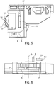
- the 1 to 6 show in different views a device 1 according to the invention for setting a closed position of a drawer 38 (see FIG. Fig. 11 ), if this over a rail guide 2 (s. Fig. 7-11 ) is movably received on a furniture body of a piece of furniture 32.
- the device 1 is designed as a drawer depth adjustment device 3 and comprises an adjustment element 4 which is rotatable on the device 1 and which is designed as an adjustment wheel 5.
- an adjustment wheel 5 By manually turning the adjusting wheel 5 in the direction D1 or in the direction D2 about an axis of rotation D that is vertical when in use, a linearly adjustable stop 6 of the device 1 is brought into different fixed adjustment positions on the device 1 and thus on the rail guide 2.
- the stop 6 specifies the closed position of the drawer, whereby a sliding movement of a drawer rail 22 of the rail guide 2 in a closing direction R2 of the drawer 38 is limited.
- a counter stop 7 of the drawer rail 22 is in contact with the stop 6, which can be preset via the adjusting wheel 5.
- the maximum possible travel of the stop 6 is, for example, up to 5 or 10 or 15 millimeters.
- the stop 6 does not form an obstacle, sections of the drawer rail 22 passing over the longitudinal extension above or possibly laterally past the stop 6.
- the adjusting wheel 5 and a sliding element 8 of the device 1 coupled to the adjusting wheel 5 are designed such that, by rotating the adjusting wheel 5 in one of the directions of rotation D1 or D2, the sliding element 8 and thus the stop 6 can be adjusted linearly in the direction R3 or in the direction R4 is.
- the directions R3 and R4 are aligned parallel to the displacement direction or opening direction R1 and closing direction R2 of the drawer 38 provided with the rail guide 2.
- the stop 6 is provided in one piece on the sliding element 8 or as a separate part thereon.
- the device 1 also comprises a base plate 9.
- the base plate 9 is designed such that the base plate 9 and thus the device 1 can be plugged into a body rail 21 which can be fixed in position on the furniture 32 or on a side wall 34 of the furniture 32. Thus, when the device 1 is in use, the base plate 9 is immovable relative to the furniture 32.
- the adjusting wheel 5 has a disk section 10 (see. Fig. 2 ) and in relation to an installed state on the top-side outer cylindrical rotary bearing section 11.
- the rotary bearing section 11 protrudes or protrudes centrally and transversely to an associated upper side of the disk section 10.
- the device 1 has a resilient plug-in section 13, which is used for correctly plugging and / or releasably securing the device 1 to the body rail 21.
- the adjusting wheel 5 is also moved linearly relative to the base plate 9 together with the sliding element 8 during the rotation.
- the adjusting wheel 5 and the base plate 9 have transmission sections 14, 15 which come into mutual contact.
- the transmission sections 14, 15 force that a linear movement of the sliding element 8 takes place simultaneously or overlapping with the rotary movement of the adjusting wheel 5.
- the transmission section 14 is associated with the adjusting wheel 5 and the transmission section 15 is associated with the base plate 9.
- the transmission section 14 on the adjusting wheel 5 is present on the underside of the disk section 10 in relation to the installed state.
- the transmission section 14 comprises a curved, elongated engaging member 16 protruding toward the relevant underside of the disk section 10, which is designed as a helical spiral web 17. A different distance from the respective point to the axis of rotation D is thus predetermined at each point of the bar 17 over the course of the bar 17.
- the transmission section 15 on the base plate 9 comprises a recessed guide section 18 which is formed between two adjacent and spaced, elevated guide bases 19 and 20.
- the engaging member 16 or a portion of the web 17 projects between the guide bases 19 and 20, so that a comparatively short longitudinal portion of the web 17 is positioned on or in the guide portion 18 between the two guide bases 19 and 20, depending on the rotational position of the Adjustment wheel 5 each has a different longitudinal section of the web 17, each with one side in between, on one side of the two guide bases 19 and 20 facing the guide section 18.
- the position of the adjusting wheel 5 and thus of the stop 6 in the adjusting direction R3 or R4 is predetermined.
- the sliding element 8 is U-shaped with an upper one Leg, which partially covers the base plate 9 at the top, and with a lower leg with the slot 27, the lower leg partially covering the base plate 9 at the bottom.
- a resilient locking member 29 of the plug section 13 is formed on the base plate 9 for plugging the device 1 onto the carcass rail 21.
- the device 1 With the plug section 13 or the locking member 29, the device 1 can be automatically locked and releasably attached to the carcass rail 21 or with an attached section on the horizontal leg 25 of the body rail 21 possible.
- a hook section 30 of the locking member 29 engages in a matching recess 31 on the body rail 21 or on the section connectable to the horizontal leg 25.
- the rail guide 2 has the body rail 21 which can be fastened to the furniture 32 and the drawer rail 22 which is displaceable relative to the body rail 21 and which can be connected to the drawer 38, with a central rail acting in between when fully extended.
- the counter stop 7 is designed, for. B. as a sheet metal plate open at the bottom, which comes into contact with its inside against a front side of the stop 6 when the drawer 38 is closed.
- An attachment angle 23 of the carcass rail 21 has a vertical leg 24 and the horizontal leg 25 projecting at right angles thereto.
- the vertical leg 24 is penetrated with screw openings 41, which are used to screw the body rail 21 to the inside of each side wall 34 with screwing means.
- FIG. 10 shows a section of the furniture 32 with attached rail guide 2 with drawer depth adjustment device 3 according to the invention 7 to 9 in perspective view.
- a section 33 of the furniture 32 shows a bottom 33, the side wall 34 and a rear wall 35. Screwing means with which the mounting bracket 23 and two further mounting brackets 36 and 37 of the body rail 21 of the rail guide 2 are screwed on the inside to the side wall 34 are not shown.
- the front end of the rail guide 2 with the drawer depth adjustment device 3 is installed flush with a front or front end face 34a of the side wall 34 and with a front or front end face 33a of the base 33.
- the furniture 32 according Fig. 10 from above shows Fig. 11 , without an upper floor comprising two opposite side walls 34 with two correspondingly constructed rail guides 2 according to the invention, each with a drawer depth adjustment device 3.
- the drawer 38 which can be mounted thereon or placed at an angle from above with a drawer front 39 and a drawer rear wall 40, component edges are only indicated with dots.
Landscapes
- Drawers Of Furniture (AREA)
Applications Claiming Priority (1)
| Application Number | Priority Date | Filing Date | Title |
|---|---|---|---|
| DE102019102378.5A DE102019102378A1 (de) | 2019-01-30 | 2019-01-30 | Vorrichtung zur Einstellung einer Schließposition einer Schublade, Korpusschiene, Schubladenführung und Schublade |
Publications (2)
| Publication Number | Publication Date |
|---|---|
| EP3689184A1 true EP3689184A1 (fr) | 2020-08-05 |
| EP3689184B1 EP3689184B1 (fr) | 2021-11-17 |
Family
ID=69167674
Family Applications (1)
| Application Number | Title | Priority Date | Filing Date |
|---|---|---|---|
| EP20151632.5A Active EP3689184B1 (fr) | 2019-01-30 | 2020-01-14 | Dispositif de réglage d'une position de fermeture d'un tiroir, rail de meuble, guidage de tiroir et tiroir |
Country Status (4)
| Country | Link |
|---|---|
| US (1) | US11033103B2 (fr) |
| EP (1) | EP3689184B1 (fr) |
| CN (1) | CN111493563B (fr) |
| DE (1) | DE102019102378A1 (fr) |
Citations (6)
| Publication number | Priority date | Publication date | Assignee | Title |
|---|---|---|---|---|
| WO2011085774A1 (fr) * | 2009-12-21 | 2011-07-21 | Grass Gmbh | Meuble et dispositif pour un meuble |
| US20120017414A1 (en) * | 2010-07-23 | 2012-01-26 | Cerniglia Anthony J | Cabinet drawer support system |
| DE202012012265U1 (de) * | 2012-12-21 | 2014-03-24 | Grass Gmbh | Vorrichtung zur Einstellung eines in einem Möbelkorpus aufgenommenen Möbelteils, Führungsvorrichtung zur Bewegung eines bewegbaren Möbelteils sowie Möbel mit einer Vorrichtung zur Einstellung eines in einem Möbelkorpus aufgenommenen Möbelteils |
| WO2016177732A1 (fr) * | 2015-05-04 | 2016-11-10 | Paul Hettich Gmbh & Co. Kg | Dispositif et procédé pour immobiliser un élément coulissant |
| DE202015107020U1 (de) * | 2015-12-22 | 2017-03-24 | Grass Gmbh | Verstellvorrichtung, Führungseinheit und Möbel |
| US20170181544A1 (en) * | 2013-11-22 | 2017-06-29 | Hardware Resources, Inc. | Undermount drawer slide position adjustment apparatus and method of use |
Family Cites Families (13)
| Publication number | Priority date | Publication date | Assignee | Title |
|---|---|---|---|---|
| AT401860B (de) * | 1993-07-20 | 1996-12-27 | Blum Gmbh Julius | Schublade |
| DE202005006724U1 (de) * | 2005-02-14 | 2005-07-28 | Grass Gmbh | Schubladenführung |
| MY151706A (en) * | 2009-08-12 | 2014-06-30 | Harn Marketing Sdn Bhd | Drawer assembly |
| US8186780B2 (en) * | 2009-11-27 | 2012-05-29 | King Slide Works Co., Ltd. | Adjustment device for slide assembly |
| AT509414B1 (de) * | 2010-02-03 | 2013-04-15 | Blum Gmbh Julius | Kupplungsvorrichtung mit seitenverstellung für eine schublade |
| AT510905A1 (de) * | 2011-01-05 | 2012-07-15 | Blum Gmbh Julius | Kupplungsvorrichtung für schubladen |
| DE102011122264B4 (de) * | 2011-12-23 | 2023-07-27 | Grass Gmbh | "Möbel, Führungseinheit und Vorrichtung bzw. Verfahren zur Anbringung einer Führungseinheit an einem Möbelteil" |
| AT512748B1 (de) * | 2012-04-13 | 2017-04-15 | Blum Gmbh Julius | Einstellvorrichtung zum Einstellen einer Lage einer Schublade |
| KR101406781B1 (ko) * | 2012-10-24 | 2014-06-17 | 박윤식 | 서랍용 슬라이드 탈착장치 |
| US8979223B2 (en) * | 2012-12-12 | 2015-03-17 | Nan Juen International Co., Ltd. | Adjustable coupling device for connection between sliding rail assembly and a sliding box |
| AT515265B1 (de) * | 2014-01-09 | 2018-07-15 | Blum Gmbh Julius | Schubladenausziehführung |
| US20160198855A1 (en) * | 2015-01-13 | 2016-07-14 | King Slide Works Co., Ltd. | Slide rail assembly and mounting device thereof |
| TWI684420B (zh) * | 2018-08-23 | 2020-02-11 | 川湖科技股份有限公司 | 可用於滑軌總成的調整機構 |
-
2019
- 2019-01-30 DE DE102019102378.5A patent/DE102019102378A1/de not_active Withdrawn
-
2020
- 2020-01-14 EP EP20151632.5A patent/EP3689184B1/fr active Active
- 2020-01-15 CN CN202010044057.7A patent/CN111493563B/zh active Active
- 2020-01-23 US US16/750,419 patent/US11033103B2/en active Active
Patent Citations (6)
| Publication number | Priority date | Publication date | Assignee | Title |
|---|---|---|---|---|
| WO2011085774A1 (fr) * | 2009-12-21 | 2011-07-21 | Grass Gmbh | Meuble et dispositif pour un meuble |
| US20120017414A1 (en) * | 2010-07-23 | 2012-01-26 | Cerniglia Anthony J | Cabinet drawer support system |
| DE202012012265U1 (de) * | 2012-12-21 | 2014-03-24 | Grass Gmbh | Vorrichtung zur Einstellung eines in einem Möbelkorpus aufgenommenen Möbelteils, Führungsvorrichtung zur Bewegung eines bewegbaren Möbelteils sowie Möbel mit einer Vorrichtung zur Einstellung eines in einem Möbelkorpus aufgenommenen Möbelteils |
| US20170181544A1 (en) * | 2013-11-22 | 2017-06-29 | Hardware Resources, Inc. | Undermount drawer slide position adjustment apparatus and method of use |
| WO2016177732A1 (fr) * | 2015-05-04 | 2016-11-10 | Paul Hettich Gmbh & Co. Kg | Dispositif et procédé pour immobiliser un élément coulissant |
| DE202015107020U1 (de) * | 2015-12-22 | 2017-03-24 | Grass Gmbh | Verstellvorrichtung, Führungseinheit und Möbel |
Also Published As
| Publication number | Publication date |
|---|---|
| US20200237094A1 (en) | 2020-07-30 |
| DE102019102378A1 (de) | 2020-07-30 |
| US11033103B2 (en) | 2021-06-15 |
| CN111493563B (zh) | 2022-07-08 |
| EP3689184B1 (fr) | 2021-11-17 |
| CN111493563A (zh) | 2020-08-07 |
Similar Documents
| Publication | Publication Date | Title |
|---|---|---|
| AT509414B1 (de) | Kupplungsvorrichtung mit seitenverstellung für eine schublade | |
| AT509416B1 (de) | Ausziehführung für eine schublade | |
| AT512748B1 (de) | Einstellvorrichtung zum Einstellen einer Lage einer Schublade | |
| WO2007118632A2 (fr) | Dispositif de guidage encastré pour éléments de meubles, en particulier de tiroirs dans le corps de meubles | |
| WO2007096156A2 (fr) | Dispositif de fixation réglable de rails de roulement de glissières télescopiques de tiroirs | |
| EP0740917A1 (fr) | Dispositif pour fixer le panneau avant de tiroir, en particulier tiroir à double paroi, sur les parois latérales | |
| AT508713B1 (de) | Vorrichtung zur halterung von flächenförmigen elementen | |
| EP3491966A1 (fr) | Dispositif de raccordement et meuble ou appareil électroménager | |
| EP2644052A1 (fr) | Dispositif destiné à déplacer une première pièce de meuble relativement à une seconde pièce de meuble | |
| EP3009039B1 (fr) | Dispositif de fixation d'un composant avant sur une section de montage d'un élément de meuble, élément de meuble et meuble | |
| EP3689184B1 (fr) | Dispositif de réglage d'une position de fermeture d'un tiroir, rail de meuble, guidage de tiroir et tiroir | |
| EP2064972B1 (fr) | Tiroir d'armoire doté d'une partie de support et d'une façade de meuble pouvant être fixée dessus | |
| EP2937025B1 (fr) | Dispositif de montage de rideaux de type panneaux japonais | |
| EP2233039B1 (fr) | Guidage pour tiroirs | |
| EP2965656A1 (fr) | Dispositif de montage pour un élément support sur une colonne porteuse | |
| DE20205667U1 (de) | Aufhängevorrichtung für Wandmöbel | |
| AT518048B1 (de) | Schubladenwand | |
| EP3166444A1 (fr) | Guidage télescopique pour une partie de meuble mobile | |
| EP3666120B1 (fr) | Dispositif de raccordement de l'avant de tiroir et tiroir | |
| DE19828233A1 (de) | Wandkonsole | |
| DE202015104529U1 (de) | Pflanzenkastenhalter | |
| DE3505614A1 (de) | Ausziehfuehrung fuer schubladen u.dgl. | |
| WO2012038062A1 (fr) | Dispositif de réglage de l'inclinaison d'une partie de meuble mobile, et meuble correspondant | |
| EP0413396A1 (fr) | Appareil domestique, notamment machine à laver le vaiselle | |
| DE202006016279U1 (de) | Führungselement für ein Bauelement |
Legal Events
| Date | Code | Title | Description |
|---|---|---|---|
| PUAI | Public reference made under article 153(3) epc to a published international application that has entered the european phase |
Free format text: ORIGINAL CODE: 0009012 |
|
| STAA | Information on the status of an ep patent application or granted ep patent |
Free format text: STATUS: THE APPLICATION HAS BEEN PUBLISHED |
|
| AK | Designated contracting states |
Kind code of ref document: A1 Designated state(s): AL AT BE BG CH CY CZ DE DK EE ES FI FR GB GR HR HU IE IS IT LI LT LU LV MC MK MT NL NO PL PT RO RS SE SI SK SM TR |
|
| AX | Request for extension of the european patent |
Extension state: BA ME |
|
| STAA | Information on the status of an ep patent application or granted ep patent |
Free format text: STATUS: REQUEST FOR EXAMINATION WAS MADE |
|
| 17P | Request for examination filed |
Effective date: 20210204 |
|
| RBV | Designated contracting states (corrected) |
Designated state(s): AL AT BE BG CH CY CZ DE DK EE ES FI FR GB GR HR HU IE IS IT LI LT LU LV MC MK MT NL NO PL PT RO RS SE SI SK SM TR |
|
| GRAP | Despatch of communication of intention to grant a patent |
Free format text: ORIGINAL CODE: EPIDOSNIGR1 |
|
| STAA | Information on the status of an ep patent application or granted ep patent |
Free format text: STATUS: GRANT OF PATENT IS INTENDED |
|
| INTG | Intention to grant announced |
Effective date: 20210715 |
|
| GRAS | Grant fee paid |
Free format text: ORIGINAL CODE: EPIDOSNIGR3 |
|
| GRAA | (expected) grant |
Free format text: ORIGINAL CODE: 0009210 |
|
| STAA | Information on the status of an ep patent application or granted ep patent |
Free format text: STATUS: THE PATENT HAS BEEN GRANTED |
|
| AK | Designated contracting states |
Kind code of ref document: B1 Designated state(s): AL AT BE BG CH CY CZ DE DK EE ES FI FR GB GR HR HU IE IS IT LI LT LU LV MC MK MT NL NO PL PT RO RS SE SI SK SM TR |
|
| REG | Reference to a national code |
Ref country code: GB Ref legal event code: FG4D Free format text: NOT ENGLISH |
|
| REG | Reference to a national code |
Ref country code: DE Ref legal event code: R096 Ref document number: 502020000344 Country of ref document: DE |
|
| REG | Reference to a national code |
Ref country code: IE Ref legal event code: FG4D Free format text: LANGUAGE OF EP DOCUMENT: GERMAN |
|
| REG | Reference to a national code |
Ref country code: AT Ref legal event code: REF Ref document number: 1447344 Country of ref document: AT Kind code of ref document: T Effective date: 20211215 |
|
| REG | Reference to a national code |
Ref country code: LT Ref legal event code: MG9D |
|
| REG | Reference to a national code |
Ref country code: NL Ref legal event code: MP Effective date: 20211117 |
|
| PG25 | Lapsed in a contracting state [announced via postgrant information from national office to epo] |
Ref country code: RS Free format text: LAPSE BECAUSE OF FAILURE TO SUBMIT A TRANSLATION OF THE DESCRIPTION OR TO PAY THE FEE WITHIN THE PRESCRIBED TIME-LIMIT Effective date: 20211117 Ref country code: LT Free format text: LAPSE BECAUSE OF FAILURE TO SUBMIT A TRANSLATION OF THE DESCRIPTION OR TO PAY THE FEE WITHIN THE PRESCRIBED TIME-LIMIT Effective date: 20211117 Ref country code: FI Free format text: LAPSE BECAUSE OF FAILURE TO SUBMIT A TRANSLATION OF THE DESCRIPTION OR TO PAY THE FEE WITHIN THE PRESCRIBED TIME-LIMIT Effective date: 20211117 Ref country code: BG Free format text: LAPSE BECAUSE OF FAILURE TO SUBMIT A TRANSLATION OF THE DESCRIPTION OR TO PAY THE FEE WITHIN THE PRESCRIBED TIME-LIMIT Effective date: 20220217 |
|
| PG25 | Lapsed in a contracting state [announced via postgrant information from national office to epo] |
Ref country code: IS Free format text: LAPSE BECAUSE OF FAILURE TO SUBMIT A TRANSLATION OF THE DESCRIPTION OR TO PAY THE FEE WITHIN THE PRESCRIBED TIME-LIMIT Effective date: 20220317 Ref country code: SE Free format text: LAPSE BECAUSE OF FAILURE TO SUBMIT A TRANSLATION OF THE DESCRIPTION OR TO PAY THE FEE WITHIN THE PRESCRIBED TIME-LIMIT Effective date: 20211117 Ref country code: PT Free format text: LAPSE BECAUSE OF FAILURE TO SUBMIT A TRANSLATION OF THE DESCRIPTION OR TO PAY THE FEE WITHIN THE PRESCRIBED TIME-LIMIT Effective date: 20220317 Ref country code: PL Free format text: LAPSE BECAUSE OF FAILURE TO SUBMIT A TRANSLATION OF THE DESCRIPTION OR TO PAY THE FEE WITHIN THE PRESCRIBED TIME-LIMIT Effective date: 20211117 Ref country code: NO Free format text: LAPSE BECAUSE OF FAILURE TO SUBMIT A TRANSLATION OF THE DESCRIPTION OR TO PAY THE FEE WITHIN THE PRESCRIBED TIME-LIMIT Effective date: 20220217 Ref country code: NL Free format text: LAPSE BECAUSE OF FAILURE TO SUBMIT A TRANSLATION OF THE DESCRIPTION OR TO PAY THE FEE WITHIN THE PRESCRIBED TIME-LIMIT Effective date: 20211117 Ref country code: LV Free format text: LAPSE BECAUSE OF FAILURE TO SUBMIT A TRANSLATION OF THE DESCRIPTION OR TO PAY THE FEE WITHIN THE PRESCRIBED TIME-LIMIT Effective date: 20211117 Ref country code: HR Free format text: LAPSE BECAUSE OF FAILURE TO SUBMIT A TRANSLATION OF THE DESCRIPTION OR TO PAY THE FEE WITHIN THE PRESCRIBED TIME-LIMIT Effective date: 20211117 Ref country code: GR Free format text: LAPSE BECAUSE OF FAILURE TO SUBMIT A TRANSLATION OF THE DESCRIPTION OR TO PAY THE FEE WITHIN THE PRESCRIBED TIME-LIMIT Effective date: 20220218 Ref country code: ES Free format text: LAPSE BECAUSE OF FAILURE TO SUBMIT A TRANSLATION OF THE DESCRIPTION OR TO PAY THE FEE WITHIN THE PRESCRIBED TIME-LIMIT Effective date: 20211117 |
|
| PG25 | Lapsed in a contracting state [announced via postgrant information from national office to epo] |
Ref country code: SM Free format text: LAPSE BECAUSE OF FAILURE TO SUBMIT A TRANSLATION OF THE DESCRIPTION OR TO PAY THE FEE WITHIN THE PRESCRIBED TIME-LIMIT Effective date: 20211117 Ref country code: SK Free format text: LAPSE BECAUSE OF FAILURE TO SUBMIT A TRANSLATION OF THE DESCRIPTION OR TO PAY THE FEE WITHIN THE PRESCRIBED TIME-LIMIT Effective date: 20211117 Ref country code: RO Free format text: LAPSE BECAUSE OF FAILURE TO SUBMIT A TRANSLATION OF THE DESCRIPTION OR TO PAY THE FEE WITHIN THE PRESCRIBED TIME-LIMIT Effective date: 20211117 Ref country code: EE Free format text: LAPSE BECAUSE OF FAILURE TO SUBMIT A TRANSLATION OF THE DESCRIPTION OR TO PAY THE FEE WITHIN THE PRESCRIBED TIME-LIMIT Effective date: 20211117 Ref country code: DK Free format text: LAPSE BECAUSE OF FAILURE TO SUBMIT A TRANSLATION OF THE DESCRIPTION OR TO PAY THE FEE WITHIN THE PRESCRIBED TIME-LIMIT Effective date: 20211117 Ref country code: CZ Free format text: LAPSE BECAUSE OF FAILURE TO SUBMIT A TRANSLATION OF THE DESCRIPTION OR TO PAY THE FEE WITHIN THE PRESCRIBED TIME-LIMIT Effective date: 20211117 |
|
| REG | Reference to a national code |
Ref country code: DE Ref legal event code: R097 Ref document number: 502020000344 Country of ref document: DE |
|
| PG25 | Lapsed in a contracting state [announced via postgrant information from national office to epo] |
Ref country code: MC Free format text: LAPSE BECAUSE OF FAILURE TO SUBMIT A TRANSLATION OF THE DESCRIPTION OR TO PAY THE FEE WITHIN THE PRESCRIBED TIME-LIMIT Effective date: 20211117 |
|
| PLBE | No opposition filed within time limit |
Free format text: ORIGINAL CODE: 0009261 |
|
| STAA | Information on the status of an ep patent application or granted ep patent |
Free format text: STATUS: NO OPPOSITION FILED WITHIN TIME LIMIT |
|
| REG | Reference to a national code |
Ref country code: BE Ref legal event code: MM Effective date: 20220131 |
|
| 26N | No opposition filed |
Effective date: 20220818 |
|
| PG25 | Lapsed in a contracting state [announced via postgrant information from national office to epo] |
Ref country code: LU Free format text: LAPSE BECAUSE OF NON-PAYMENT OF DUE FEES Effective date: 20220114 Ref country code: AL Free format text: LAPSE BECAUSE OF FAILURE TO SUBMIT A TRANSLATION OF THE DESCRIPTION OR TO PAY THE FEE WITHIN THE PRESCRIBED TIME-LIMIT Effective date: 20211117 |
|
| PG25 | Lapsed in a contracting state [announced via postgrant information from national office to epo] |
Ref country code: SI Free format text: LAPSE BECAUSE OF FAILURE TO SUBMIT A TRANSLATION OF THE DESCRIPTION OR TO PAY THE FEE WITHIN THE PRESCRIBED TIME-LIMIT Effective date: 20211117 Ref country code: FR Free format text: LAPSE BECAUSE OF NON-PAYMENT OF DUE FEES Effective date: 20220117 Ref country code: BE Free format text: LAPSE BECAUSE OF NON-PAYMENT OF DUE FEES Effective date: 20220131 |
|
| PG25 | Lapsed in a contracting state [announced via postgrant information from national office to epo] |
Ref country code: IE Free format text: LAPSE BECAUSE OF NON-PAYMENT OF DUE FEES Effective date: 20220114 |
|
| REG | Reference to a national code |
Ref country code: CH Ref legal event code: PL |
|
| PG25 | Lapsed in a contracting state [announced via postgrant information from national office to epo] |
Ref country code: LI Free format text: LAPSE BECAUSE OF NON-PAYMENT OF DUE FEES Effective date: 20230131 Ref country code: CH Free format text: LAPSE BECAUSE OF NON-PAYMENT OF DUE FEES Effective date: 20230131 |
|
| PG25 | Lapsed in a contracting state [announced via postgrant information from national office to epo] |
Ref country code: MK Free format text: LAPSE BECAUSE OF FAILURE TO SUBMIT A TRANSLATION OF THE DESCRIPTION OR TO PAY THE FEE WITHIN THE PRESCRIBED TIME-LIMIT Effective date: 20211117 Ref country code: CY Free format text: LAPSE BECAUSE OF FAILURE TO SUBMIT A TRANSLATION OF THE DESCRIPTION OR TO PAY THE FEE WITHIN THE PRESCRIBED TIME-LIMIT Effective date: 20211117 |
|
| PG25 | Lapsed in a contracting state [announced via postgrant information from national office to epo] |
Ref country code: HU Free format text: LAPSE BECAUSE OF FAILURE TO SUBMIT A TRANSLATION OF THE DESCRIPTION OR TO PAY THE FEE WITHIN THE PRESCRIBED TIME-LIMIT; INVALID AB INITIO Effective date: 20200114 |
|
| PG25 | Lapsed in a contracting state [announced via postgrant information from national office to epo] |
Ref country code: MT Free format text: LAPSE BECAUSE OF FAILURE TO SUBMIT A TRANSLATION OF THE DESCRIPTION OR TO PAY THE FEE WITHIN THE PRESCRIBED TIME-LIMIT Effective date: 20211117 |
|
| REG | Reference to a national code |
Ref country code: DE Ref legal event code: R082 Ref document number: 502020000344 Country of ref document: DE Representative=s name: RAVENSPAT PATENTANWAELTE PARTNERSCHAFT MBB, DE |
|
| PG25 | Lapsed in a contracting state [announced via postgrant information from national office to epo] |
Ref country code: TR Free format text: LAPSE BECAUSE OF FAILURE TO SUBMIT A TRANSLATION OF THE DESCRIPTION OR TO PAY THE FEE WITHIN THE PRESCRIBED TIME-LIMIT Effective date: 20211117 |
|
| PGFP | Annual fee paid to national office [announced via postgrant information from national office to epo] |
Ref country code: GB Payment date: 20260123 Year of fee payment: 7 |
|
| PGFP | Annual fee paid to national office [announced via postgrant information from national office to epo] |
Ref country code: DE Payment date: 20260121 Year of fee payment: 7 |
|
| PGFP | Annual fee paid to national office [announced via postgrant information from national office to epo] |
Ref country code: AT Payment date: 20260122 Year of fee payment: 7 |
|
| PGFP | Annual fee paid to national office [announced via postgrant information from national office to epo] |
Ref country code: IT Payment date: 20260126 Year of fee payment: 7 |