EP3689314A1 - Agencement de base de puissance modulaire - Google Patents
Agencement de base de puissance modulaire Download PDFInfo
- Publication number
- EP3689314A1 EP3689314A1 EP20154331.1A EP20154331A EP3689314A1 EP 3689314 A1 EP3689314 A1 EP 3689314A1 EP 20154331 A EP20154331 A EP 20154331A EP 3689314 A1 EP3689314 A1 EP 3689314A1
- Authority
- EP
- European Patent Office
- Prior art keywords
- wheel
- omni
- foot
- leg
- assembly
- Prior art date
- Legal status (The legal status is an assumption and is not a legal conclusion. Google has not performed a legal analysis and makes no representation as to the accuracy of the status listed.)
- Granted
Links
Images


Classifications
-
- A—HUMAN NECESSITIES
- A61—MEDICAL OR VETERINARY SCIENCE; HYGIENE
- A61G—TRANSPORT, PERSONAL CONVEYANCES, OR ACCOMMODATION SPECIALLY ADAPTED FOR PATIENTS OR DISABLED PERSONS; OPERATING TABLES OR CHAIRS; CHAIRS FOR DENTISTRY; FUNERAL DEVICES
- A61G5/00—Chairs or personal conveyances specially adapted for patients or disabled persons, e.g. wheelchairs
- A61G5/06—Chairs or personal conveyances specially adapted for patients or disabled persons, e.g. wheelchairs with obstacle mounting facilities, e.g. for climbing stairs, kerbs or steps
-
- A—HUMAN NECESSITIES
- A61—MEDICAL OR VETERINARY SCIENCE; HYGIENE
- A61G—TRANSPORT, PERSONAL CONVEYANCES, OR ACCOMMODATION SPECIALLY ADAPTED FOR PATIENTS OR DISABLED PERSONS; OPERATING TABLES OR CHAIRS; CHAIRS FOR DENTISTRY; FUNERAL DEVICES
- A61G5/00—Chairs or personal conveyances specially adapted for patients or disabled persons, e.g. wheelchairs
- A61G5/04—Chairs or personal conveyances specially adapted for patients or disabled persons, e.g. wheelchairs motor-driven
- A61G5/041—Chairs or personal conveyances specially adapted for patients or disabled persons, e.g. wheelchairs motor-driven having a specific drive-type
- A61G5/042—Front wheel drive
-
- A—HUMAN NECESSITIES
- A61—MEDICAL OR VETERINARY SCIENCE; HYGIENE
- A61G—TRANSPORT, PERSONAL CONVEYANCES, OR ACCOMMODATION SPECIALLY ADAPTED FOR PATIENTS OR DISABLED PERSONS; OPERATING TABLES OR CHAIRS; CHAIRS FOR DENTISTRY; FUNERAL DEVICES
- A61G5/00—Chairs or personal conveyances specially adapted for patients or disabled persons, e.g. wheelchairs
- A61G5/04—Chairs or personal conveyances specially adapted for patients or disabled persons, e.g. wheelchairs motor-driven
- A61G5/041—Chairs or personal conveyances specially adapted for patients or disabled persons, e.g. wheelchairs motor-driven having a specific drive-type
- A61G5/043—Mid wheel drive
-
- A—HUMAN NECESSITIES
- A61—MEDICAL OR VETERINARY SCIENCE; HYGIENE
- A61G—TRANSPORT, PERSONAL CONVEYANCES, OR ACCOMMODATION SPECIALLY ADAPTED FOR PATIENTS OR DISABLED PERSONS; OPERATING TABLES OR CHAIRS; CHAIRS FOR DENTISTRY; FUNERAL DEVICES
- A61G5/00—Chairs or personal conveyances specially adapted for patients or disabled persons, e.g. wheelchairs
- A61G5/06—Chairs or personal conveyances specially adapted for patients or disabled persons, e.g. wheelchairs with obstacle mounting facilities, e.g. for climbing stairs, kerbs or steps
- A61G5/061—Chairs or personal conveyances specially adapted for patients or disabled persons, e.g. wheelchairs with obstacle mounting facilities, e.g. for climbing stairs, kerbs or steps for climbing stairs
-
- A—HUMAN NECESSITIES
- A61—MEDICAL OR VETERINARY SCIENCE; HYGIENE
- A61G—TRANSPORT, PERSONAL CONVEYANCES, OR ACCOMMODATION SPECIALLY ADAPTED FOR PATIENTS OR DISABLED PERSONS; OPERATING TABLES OR CHAIRS; CHAIRS FOR DENTISTRY; FUNERAL DEVICES
- A61G5/00—Chairs or personal conveyances specially adapted for patients or disabled persons, e.g. wheelchairs
- A61G5/10—Parts, details or accessories
- A61G5/1056—Arrangements for adjusting the seat
- A61G5/1059—Arrangements for adjusting the seat adjusting the height of the seat
Definitions
- the present disclosure generally relates to systems and/or methods for transitioning a wheelchair assembly, including a plurality of leg modules, between various modes of operation.
- a wheelchair assembly including a control device, a power base, and a plurality of leg modules coupled to the power base.
- the plurality of leg modules may include a first leg module, a second leg module, and a third leg module.
- Each of the first leg module, the second leg module, and the third leg module may include an upper leg assembly, a lower leg assembly, a knee wheel, and a foot wheel.
- Each lower leg assembly may include a knee joint and a foot joint and each lower leg assembly may rotatably couple to each upper leg assembly at the knee joint.
- the knee wheel may be located at the knee joint of each lower leg assembly, may include an omni-directional wheel, and may be selectively drivable.
- the foot wheel may be located at the foot joint of each lower leg assembly and may be selectively drivable.
- the control device based on a selectable mode of operation, may control at least one of the upper leg assembly or the lower leg assembly associated with each respective leg module to selectively position at least one of the knee wheel or the foot wheel associated with each respective leg module relative to a surface.
- a leg module of a wheelchair assembly including an upper leg assembly, a lower leg assembly, a knee wheel, and a foot wheel
- the lower leg assembly may include a knee joint and a foot joint and may rotatably couple to the upper leg assembly at the knee joint.
- the knee wheel may be located at the knee joint of the lower leg assembly, may include an omni-directional wheel, and may be selectively drivable.
- the foot wheel may be located at the foot joint of the lower leg assembly and may be selectively drivable.
- At least one of the upper leg assembly or the lower leg assembly associated with the leg module may be controllable, based on a selectable mode of operation, to selectively position at least one of the omni-directional knee wheel or the foot wheel associated with the leg module relative to a surface.
- a system including a control device, a power base, and a plurality of leg modules coupled to the power base.
- the plurality of leg modules may include a first leg module, a second leg module, and a third leg module.
- Each of the first leg module, the second leg module, and the third leg module may include an upper leg assembly, a lower leg assembly, a knee wheel, and a foot wheel.
- Each lower leg assembly may include a knee joint and a foot joint and each lower leg assembly may rotatably coupled to each upper leg assembly at the knee joint.
- the knee wheel may be located at the knee joint of each lower leg assembly, may include an omni-directional wheel, and may be selectively drivable.
- the foot wheel may be located at the foot joint of each lower leg assembly and may be selectively drivable.
- the control device may control at least one of the first leg module, the second leg module or the third leg module, either independently or simultaneously, to transition the system between a front-wheel drive mode configuration, a mid-wheel drive mode configuration, and an omni-drive mode configuration.
- the present disclosure relates to a system including a wheelchair assembly having a modular power base including various arrangements of driven and/or non-driven wheels selectively positioned in or out of contact with the ground based on a selected mode of operation.
- the driven and/or non-driven wheels may include standard wheels and/or omni-directional wheels.
- the various modes of operation may increase the efficiency and the maneuverability of the wheelchair assembly.
- operating the wheelchair assembly in a particular mode of operation may assist a user of the wheelchair assembly during activities of daily living.
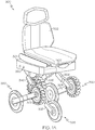
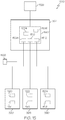
- FIG. 1A depicts an illustrative wheelchair assembly 300 having a plurality of leg modules (e.g., a first leg module 380, a second leg module 385, and a third leg module 390) according to one or more embodiments described herein.
- the wheelchair assembly 300 may further include a seat 302 and a power base 304.
- the power base 304 may include a control device 1502 (shown in phantom, e.g., a processor and/or the like) to control movement of the leg modules 380, 385, 390 and components thereof and/or to transition the leg modules 380, 385, 390 between various modes of operation, as described herein.
- FIG. 1502 shown in phantom, e.g., a processor and/or the like
- the first leg module 380 may include an upper leg assembly 306 rotatably coupled to a lower leg assembly 308.
- the lower leg assembly 308 may include at least two wheels 314, 316.
- the wheels 314, 316 may be omni-directional wheels or standard wheels.
- a standard wheel may include any wheel configured to move in a forward or distal "D" direction and/or a reverse or proximal "P" direction (e.g., uni-directional or bi-directional) and an omni-directional wheel may include any wheel that enables omni-directional movement (e.g., a mecanum wheel, an omni-wheel, a caster, and/or the like).
- wheel 314 is a standard wheel and wheel 316 is a mecanum wheel.
- the second leg module 385 may include an upper leg assembly 326 rotatably coupled to a lower leg assembly 328.
- the lower leg assembly 328 may include at least two wheels 334, 336a, 336b.
- the wheels 334, 336a, 336b may be omni-directional wheels or standard wheels.
- wheel 334 is a standard wheel and wheels 336a and 336b are mecanum wheels.
- the third leg module 390 may include an upper leg assembly 346 rotatably coupled to a lower leg assembly 348.
- the lower leg assembly 348 may include at least two wheels 354, 356.
- the wheels 354, 356 may be omni-directional wheels or standard wheels.
- wheel 354 is a standard wheel and the wheels 356 is a mecanum wheel.
- the wheelchair assembly 300 of FIGS. 1A and 1B includes three leg modules, it should be understood that the wheelchair assembly 300 may alternatively include more than three leg modules (e.g., four leg modules, five leg modules, and/or the like). However, the wheelchair assembly 300 of FIGS. 1A and 1B does not include few than three leg modules
- the leg modules 380, 385, 390 of FIGS. 1A and 1B may realize multiple functionalities of the wheelchair assembly 300.
- the leg modules 380, 385, 390 may drive the wheelchair assembly 300, may raise and/or lower various components (e.g., seat 302, power base 304, and/or the like) of the wheelchair assembly 300, may balance or support or stabilize the various components of the wheelchair assembly 300, may steer the wheelchair assembly 300, and/or the like.
- each leg module 380, 385, 390 may be coupled to the power base 304 via each respective upper leg assembly 306, 326, 346.
- each of the upper leg assembly 306 of the first leg module 380 and the upper leg assembly 346 of the third leg module 390 respectively may rotatably couple to a proximal portion 392 of the power base 304 and extend distally at an angle relative to the power base 304.
- the upper leg assembly 326 of the second leg module 385 may rotatably couple to a distal portion 394 of the power base 304 and extend proximally at an angle relative to the power base 304.
- each respective upper leg assembly 306, 326, 346 may couple to a proximal portion of the power base 304 and extend distally at an angle relative to the power base 304. According to another alternative aspect (not shown), each respective upper leg assembly 306, 326, 346 may couple to a distal portion of the power base 304 and extend proximally at an angle relative to the power base 304.
- Each upper leg assembly 306, 326, 346 may be actuated independently, consecutively, or simultaneously (e.g., in synchronization with) as another upper leg assembly.
- each upper leg assembly 306, 326, 346 may be actuated independently, consecutively, or simultaneously as another upper leg assembly based on a selected mode of operation associated with the wheelchair assembly 300 (e.g., rear-wheel drive (RWD) mode, front-wheel drive (FWD) mode, mid-wheel drive (MWD) mode, and/or omni-wheel drive (OWD) mode), as discussed herein.
- each lower leg assembly 308, 328, 348 may be actuated independently, consecutively, or simultaneously (e.g., in synchronization with) as another lower leg assembly.
- each lower leg assembly 308, 328, 348 may be actuated independently, consecutively, or simultaneously as another lower leg assembly based on a selected mode of operation associated with the wheelchair assembly 300 (e.g., rear-wheel drive (RWD) mode, front-wheel drive (FWD) mode, mid-wheel drive (MWD) mode, and/or omni-wheel drive (OWD) mode), as discussed herein.
- a selected mode of operation associated with the wheelchair assembly 300 e.g., rear-wheel drive (RWD) mode, front-wheel drive (FWD) mode, mid-wheel drive (MWD) mode, and/or omni-wheel drive (OWD) mode
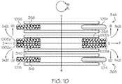
- each leg module as described herein may include a lower leg assembly 200 having at least two wheels 202, 204 and at least one drive train 206a, 206b for selectively applying rotary motion from a motor 208 of the lower leg assembly 200 to either or both of the wheels 202, 204.
- the drive train 206a may include one or more of a clutch 210a and a drive element 212a (e.g., a drive belt, a drive shaft, gears, and/or the like).
- the drive train 206b may include one or more of a clutch 210b and a drive element 212b (e.g., a drive belt, a drive shaft, gears, and/or the like).
- the clutch may shift between a plurality of modes, including, but not limited to, a neutral mode, a knee-wheel powered mode, a foot-wheel powered mode, and a bi-wheel powered mode (e.g., a knee-wheel and foot-wheel powered mode).
- either or both of the wheels 202, 204 may be an omni-directional wheel.
- either or both of the wheels 202, 204 may be a standard (e.g., bi-directional) wheel.
- wheel 202 is an omni-directional wheel (e.g., stipple shaded)
- wheel 204 is a standard (e.g., bi-directional) wheel (e.g., lined, not stipple shaded).
- a motor 208a, 208b may be positioned at or proximate to each wheel 202, 204 of a lower leg assembly 200'.
- a drive train 206a, 206b (e.g., similar to as described in FIG. 2A ) coupled to each respective wheel 202, 204 may selectively apply rotary motion from each respective motor 208a, 208b to each respective wheel 202, 204.
- each motor 208a, 208b may directly drive each wheel 202, 204 without a drive train.
- either or both of the wheels 202, 204 may be an omni-directional wheel.
- either or both of the wheels 202, 204 may be a standard (e.g., bi-directional) wheel.
- wheel 202 is an omni-directional wheel (e.g., stipple shaded) and wheel 204 is a standard (e.g., bi-directional) wheel (e.g., lined, not stipple shaded).
- FIG. 1B illustrates a bottom view of the leg modules 380, 385, 390
- FIG. 3B illustrates a top view of the various leg modules when the wheelchair assembly 300 is oriented as illustrated in FIG. 3A
- FIG. 3B illustrates an alternative embodiment (e.g., a two-bracket embodiment) of the lower leg assembly 308, the lower leg assembly 328, and the lower leg assembly 348.
- the one-bracket lower leg assembly embodiments of FIG. 1A and 1B and the two-bracket lower leg assembly embodiments of FIG. 3B are non-limiting in the present disclosure.
- the lower leg assembly 308 of first leg module 380 may include a first leg bracket 310 (e.g., outer, laterally-facing bracket relative to central axis A-A) and a second leg bracket 312 (e.g., inner, laterally-facing bracket relative to the central axis A-A)
- a foot wheel 314 and a knee wheel 316 may each be positioned between and rotatably coupled to the first leg bracket 310 and the second leg bracket 312.
- the foot wheel 314 and the knee wheel 316 may each be rotatably coupled to one side of the first leg bracket 310 or the second leg bracket 312.
- the first leg module 380 may include only one of the first leg bracket 310 or the second leg bracket 312 (e.g., see FIGS. 1A and 1B ).
- the knee wheel 316 may be referenced as the "knee” wheel as it is positioned at a distal portion (e.g., in the "D" direction of the coordinate axes of FIG. 3B ) of the lower leg assembly 308 at pivotable knee joint 318.
- the foot wheel 314 may be referenced as the "foot” wheel as it is positioned at a proximal portion (e.g., in the "P" direction of the coordinate axes of FIG.
- the knee wheel 316 associated with first leg module 380 may be an omni-directional wheel (e.g., stipple shaded) and the foot wheel 314 associated with first leg module 380 may be a standard wheel (e.g., lined, not stipple shaded).
- the lower leg assembly 328 of second leg module 385 may include a first leg bracket 330 (e.g., outer, laterally-facing bracket relative to central axis A-A) and a second leg bracket 332 (e.g., outer, laterally-facing bracket relative to central axis A-A).
- a foot wheel 334 and a knee wheel 336 may each be positioned between and rotatably coupled to the first leg bracket 330 and the second leg bracket 332.
- the foot wheel 334 and the knee wheel 336 may each be rotatably coupled to one side of the first leg bracket 330 or the second leg bracket 332.
- the second leg module 385 may include only one of the first leg bracket 330 or the second leg bracket 332 (e.g. see FIGS. 1A and 1B ).
- the upper leg assembly 326 of the second leg module 385 may couple to a distal portion of the power base 304 and may extend proximally at an angle relative to the power base 304.
- the knee wheel 336 may be referenced as the "knee" wheel as it is positioned at a proximal portion (e.g., in the "P" direction of the coordinate axes of FIG. 3B ) of the lower leg assembly 328 at pivotable knee joint 338.
- the foot wheel 334 may be referenced as the "foot” wheel as it is positioned at a distal portion (e.g., in the "D" direction of the coordinate axes of FIG. 3B ) of the lower leg assembly 328 at foot joint 340.
- the knee wheel 336 associated with second leg module 385 may be an omni-directional wheel (e.g., stipple shaded) and the foot wheel 334 associated with second leg module 385 may also be an omni-directional wheel (e.g., stipple shaded).
- the knee wheel 336 associated with second leg module 385 may be at least one omni-directional wheel (see FIG. 1B , references 336a and 336b) and the foot wheel 334 associated with second leg module 385 may be a standard wheel (see FIG. 1B , e.g., lined, not stipple shaded).
- the lower leg assembly 348 of third leg module 390 may include a first leg bracket 350 (e.g., inner, laterally-facing bracket relative to central axis A-A) and a second leg bracket 352 (e.g., outer, laterally-facing bracket relative to the central axis A-A).
- a foot wheel 354 and a knee wheel 356 may each be positioned between and rotatably coupled to the first leg bracket 350 and the second leg bracket 352.
- the foot wheel 354 and the knee wheel 356 may each be rotatably coupled to one side of the first leg bracket 350 or the second leg bracket 352.
- the third leg module 390 may include only one of the first leg bracket 350 or the second leg bracket 352 (e.g., see FIGS. 1A and 1B ).
- the knee wheel 356 may be referenced as the "knee” wheel as it is positioned at a distal portion (e.g., in the "D" direction of the coordinate axes of FIG. 3B ) of the lower leg assembly 348 at pivotable knee joint 358.
- the foot wheel 354 may be referenced as the "foot” wheel as it is positioned at a proximal portion (e.g., in the "P" direction of the coordinate axes of FIG. 3B ) of the lower leg assembly 348 at foot joint 360.
- the knee wheel 356 associated with third leg module 390 may be an omni-directional wheel (e.g., stipple shaded) and the foot wheel 354 associated with third leg module 390 may be a standard wheel (e.g., lined, not stipple shaded).
- each leg module 380, 385, 390 may include components arranged to move each respective leg module 380, 385, 390 and/or elements of each leg module 380, 385, 390.
- the upper leg assembly 306 and/or the lower leg assembly 308 of first leg module 380 may include elements actuatable to raise and/or lower the lower leg assembly 308.
- the actuatable elements may include a cable system, a linkage system, a hydraulic system, a gear system, motors (e.g., servomotors, stepper motors), and/or the like.
- the upper leg assembly 326 and/or the lower leg assembly 328 of second leg module 385 may include elements actuatable to raise and/or lower the lower leg assembly 328.
- the actuatable elements may include a cable system, a linkage system, a hydraulic system, a gear system, motors (e.g., servomotors, stepper motors), and/or the like.
- the upper leg assembly 346 and/or the lower leg assembly 348 of third leg module 390 may include elements actuatable to raise and/or lower the lower leg assembly 348.
- the actuatable elements may include a cable system, a linkage system, a hydraulic system, a gear system, motors (e.g., servomotors, stepper motors), and/or the like. Numerous components arranged to actuate each respective leg module 380, 385, 390 and/or elements of each leg module 380, 385, 390 beyond those described herein should be generally understood and are included within the scope of the present disclosure.
- the upper leg assembly 306 and/or the lower leg assembly 308 of first leg module 380 may define an enclosure to house and/or to mount elements (e.g., motors and/or drive trains as described in FIGS. 2A and 2B herein, electrical wires supplying power and/or control signals to the motors, and/or the like) to selectively raise, lower, and/or power the wheels 314 and/or 316.
- the upper leg assembly 326 and/or the lower leg assembly 328 of second leg module 385 may define an enclosure to house and/or to mount elements (e.g., motors and/or drive trains as described in FIGS.
- the upper leg assembly 346 and/or the lower leg assembly 348 of third leg module 390 may define an enclosure to house and/or to mount elements (e.g., motors and/or drive trains as described in FIGS. 2A and 2B herein, electrical wires supplying power and/or control signals to the motors, and/or the like) to selectively raise, lower and/or power the wheels 354 and/or 356.
- elements e.g., motors and/or drive trains as described in FIGS. 2A and 2B herein, electrical wires supplying power and/or control signals to the motors, and/or the like
- the present disclosure is not limited to such and it should be understood that the elements may be housed, mounted, attached, and/or the like by other means.
- upper leg assembly 306 of first leg module 380 may be selectively rotatable about hip pivot 322 in a first direction (e.g., clockwise) to raise at least one of the knee wheel 316 or the foot wheel 314 (e.g., with further counter-rotation of the lower leg module 308) off of a surface 364 (e.g., ground, floor, and/or the like) and may be selectively rotatable about the hip pivot 322 in a second direction (e.g., counter-clockwise) to position at least one of the knee wheel 316 or the foot wheel 314 (e.g., with further counter-rotation of the lower leg module 308) in contact with the surface 364.
- a first direction e.g., clockwise
- a surface 364 e.g., ground, floor, and/or the like
- a second direction e.g., counter-clockwise
- upper leg assembly 306 may be selectively rotatable about hip pivot 322 in a first direction (e.g., clockwise) to advance the foot wheel 314 from a proximal "P" position relative to axis B-B toward a distal "D" position relative to axis B-B (see FIG. 3A ) and may be selectively rotatable about hip pivot 322 in a second direction (e.g., counter-clockwise) to retreat the foot wheel 314 from a distal "D" position relative to axis B-B toward a proximal "P” position relative to axis B-B (see FIG. 3A ).
- upper leg assembly 306 is rotatable about the hip pivot 322 via a rotating mechanism (e.g., a motor, gears, and/or the like), within the power base 304, coupled to the upper leg assembly 306.
- a rotating mechanism e.g., a motor, gears, and/or the like
- the upper leg assembly 326 of second leg module 385 may be selectively rotatable about hip pivot 342 in a first direction (e.g., counter-clockwise) to raise at least one of the knee wheel 336 or the foot wheel 334 (e.g., with further counter-rotation of the lower leg module 328) off of a surface 364 (e.g., ground, floor, and/or the like) and may be selectively rotatable about the hip pivot 342 in a second direction (e.g., clockwise) to position at least one of the knee wheel 336 or the foot wheel 334 (e.g., with further counter-rotation of the lower leg module 328) in contact with the surface 364.
- a first direction e.g., counter-clockwise
- a surface 364 e.g., ground, floor, and/or the like
- a second direction e.g., clockwise
- upper leg assembly 326 may be selectively rotatable about hip pivot 342 in a first direction (e.g., counter-clockwise) to advance the foot wheel 334 from a distal "D" position relative to axis B-B toward a proximal "P" position relative to axis B-B (see FIG. 3A ) and may be selectively rotatable about hip pivot 342 in a second direction (e.g., clockwise) to retreat the foot wheel 334 from a proximal "P" position relative to axis B-B toward a distal "D” position relative to axis B-B (see FIG. 3A .
- upper leg assembly 326 is rotatable about the hip pivot 342 via a rotating mechanism (e.g., a motor, gears, and/or the like), within the power base 304, coupled to the upper leg assembly 326.
- a rotating mechanism e.g., a motor, gears, and/or the like
- the upper leg assembly 346 of third leg module 390 may be selectively rotatable about hip pivot 362 ( FIG. 1A ) in a first direction (e.g., clockwise) to raise at least one of the knee wheel 356 or the foot wheel 354 (e.g., with further counter-rotation of the lower leg module 348) off of a surface 364 (e.g., ground, floor, and/or the like) and may be selectively rotatable about the hip pivot 362 in a second direction (e.g., counter-clockwise) to position at least one of the knee wheel 356 or the foot wheel 354 (e.g., with further counter-rotation of the lower leg module 328) in contact with the surface 364.
- a first direction e.g., clockwise
- a surface 364 e.g., ground, floor, and/or the like
- a second direction e.g., counter-clockwise
- upper leg assembly 346 may be selectively rotatable about hip pivot 362 in a first direction (e.g., clockwise) to advance the foot wheel 354 from a proximal "P" position relative to axis B-B toward a distal "D" position relative to axis B-B (see FIG. 3A ) and may be selectively rotatable about hip pivot 362 in a second direction (e.g., counter-clockwise) to retreat the foot wheel 334 from a distal "D" position relative to axis B-B toward a proximal "P” position relative to axis B-B (see FIG. 3A ).
- upper leg assembly 346 is rotatable about the hip pivot 362 via a rotating mechanism (e.g., a motor, gears, and/or the like), within the power base 304, coupled to the upper leg assembly 346.
- a rotating mechanism e.g., a motor, gears, and/or the like
- lower leg assembly 308 of first leg module 380 may be selectively rotatable about knee joint 318 in a first direction (e.g., counter-clockwise) to raise the foot wheel 314 off of a surface 364 (e.g., ground, floor, and/or the like) and may be selectively rotatable about knee joint 318 in a second direction (e.g., clockwise) to position the foot wheel 314 in contact with the surface 364.
- a first direction e.g., counter-clockwise
- a second direction e.g., clockwise
- lower leg assembly 308 may be selectively rotatable about knee joint 318 in a first direction (e.g., counter-clockwise) while upper leg assembly 306 is selectively rotated about hip pivot 322 in a second direction (e.g., clockwise) to raise at least one of the knee wheel 316 or the foot wheel 314 off of a surface 364 (e.g., ground, floor, and/or the like) or to lower the seat 302 of the wheelchair assembly 300 toward the surface 364.
- a surface 364 e.g., ground, floor, and/or the like
- Such rotation of the lower leg assembly 308 about knee joint 318 may enable the first leg bracket 310 and/or the second leg bracket 312 of the lower leg assembly 308 to remain substantially parallel (e.g., to axis C-C depicted in FIG.
- lower leg assembly 308 may be selectively rotatable about knee joint 318 in a second direction (e.g., clockwise) while upper leg assembly 306 is selectively rotated about hip pivot 322 in a second direction (e.g., counter-clockwise) to position the at least one of the knee wheel 316 or the foot wheel 314 in contact with the surface 364 or to raise the seat 302 of the wheelchair assembly 300 away from the surface 364.
- Such rotation of the lower leg assembly 308 about knee joint 318 may enable the first leg bracket 310 and/or the second leg bracket 312 of the lower leg assembly 308 to remain substantially parallel (e.g., to axis C-C depicted in FIG.
- lower leg assembly 328 of second leg module 385 may be selectively rotatable about knee joint 338 in a first direction (e.g., clockwise) to raise the foot wheel 334 off of a surface 364 (e.g., ground, floor, and/or the like) and may be selectively rotatable about knee joint 338 in a second direction (e.g., counter-clockwise) to position the foot wheel 334 in contact with the surface 364.
- a first direction e.g., clockwise
- a surface 364 e.g., ground, floor, and/or the like
- second direction e.g., counter-clockwise
- lower leg assembly 328 may be selectively rotatable about knee joint 338 in a first direction (e.g., clockwise) while upper leg assembly 326 is selectively rotated about hip pivot 342 in a first direction (e.g., counter-clockwise) to raise at least one of the knee wheel 336 or the foot wheel 334 off of a surface 364 (e.g., ground, floor, and/or the like) or to lower the seat 302 of the wheelchair assembly 300 toward the surface 364.
- a surface 364 e.g., ground, floor, and/or the like
- Such rotation of the lower leg assembly 328 about knee joint 338 may enable the first leg bracket 330 and/or the second leg bracket 332 of the lower leg assembly 328 to remain substantially parallel (e.g., to axis C-C depicted in FIG.
- lower leg assembly 328 may be selectively rotatable about knee joint 338 in a second direction (e.g., counter-clockwise) while upper leg assembly 326 is selectively rotated about hip pivot 342 in a second direction (e.g., clockwise) to position the at least one of the knee wheel 336 or the foot wheel 334 in contact with the surface 364 or to raise the seat 302 of the wheelchair assembly 300 away from the surface 364.
- Such rotation of the lower leg assembly 328 about knee joint 338 may enable the first leg bracket 330 and/or the second leg bracket 332 to remain substantially parallel (e.g., to axis C-C depicted in FIG.
- lower leg assembly 348 of third leg module 390 may be selectively rotatable about knee joint 358 in a first direction (e.g., counter-clockwise) to raise the foot wheel 354 off of a surface 364 (e.g., ground, floor, and/or the like) and may be selectively rotatable about knee joint 358 in a second direction (e.g., clockwise) to position the foot wheel 354 in contact with the surface 364.
- first direction e.g., counter-clockwise
- a second direction e.g., clockwise
- lower leg assembly 348 may be selectively rotatable about knee joint 358 in a first direction (e.g., counter-clockwise) while upper leg assembly 346 is selectively rotated about hip pivot 362 in a first direction (e.g., clockwise) to raise at least one of the knee wheel 356 or the foot wheel 354 off of a surface 364 (e.g., ground, floor, and/or the like) or to lower the seat 302 of the wheelchair assembly 300 toward the surface 364.
- a surface 364 e.g., ground, floor, and/or the like
- Such rotation of the lower leg assembly 348 about knee joint 358 may enable the first leg bracket 350 and/or the second leg bracket 352 of the lower leg assembly 348 to remain substantially parallel (e.g., to axis C-C depicted in FIG.
- lower leg assembly 348 may be selectively rotatable about knee joint 358 in a second direction (e.g., clockwise) while upper leg assembly 346 is selectively rotated about hip pivot 362 in a second direction (e.g., counter clockwise) to position the at least one of the knee wheel 356 or the foot wheel 354 in contact with the surface 364 or to raise the seat 302 of the wheelchair assembly 300 away from the surface 364.
- Such rotation of the lower leg assembly 348 about knee joint 358 may enable the first leg bracket 350 and/or the second leg bracket 352 to remain substantially parallel (e.g., to axis C-C depicted in FIG.
- a drive train having a clutch enables selective driving or powering of a wheelchair assembly 300 including the plurality of leg modules 380, 385, 390.
- the wheels 314 and/or 316 of first leg module 380, the wheels 334 and/or 336 of second leg module 385, and/or the wheels 354 and/or 356 of third leg module 390 may be selectively engaged to drive or power the wheelchair assembly 300 on demand as required to improve maneuverability of the wheelchair assembly 300.
- driving or powering a wheel may refer to rotating the wheel in a first direction (e.g., counter-clockwise) to move or propel the wheelchair assembly 300 forward or distally (e.g., in the "D" direction of the coordinate axes of FIG. 3B ), rotating the wheel in a second direction (e.g., clockwise) to move or propel the wheelchair assembly 300 backward or proximally (e.g., in the "P" direction of the coordinate axes of FIG.
- a first direction e.g., counter-clockwise
- a second direction e.g., clockwise
- FIG. 11 e.g., counter-clockwise about axis I-I that is perpendicular to an axis of the wheel J-J
- first direction e.g., counter-clockwise about axis I-I that is perpendicular to an axis of the wheel J-J
- first lateral direction e.g., in the "LD1" direction of the coordinate axes of FIG. 3B
- rotating the plurality of rollers positioned circumferentially about the wheel in a second direction see FIG.
- first direction e.g., counter-clockwise
- first direction e.g., counter-clockwise
- first general direction e.g., an "AD1" direction of the coordinate axes of FIG. 3B
- distal direction e.g., the "D” direction of the coordinate axes of FIG. 3B
- first lateral direction e.g., the "LD1" direction of the coordinate axes of FIG.
- FIG. 11 rotating the plurality of rollers positioned circumferentially about the wheel in a second direction (see FIG. 11 , e.g., clockwise about the axis K-K that is perpendicular to the axis of rotation I-I) and then rotating the plurality of rollers positioned circumferentially about the wheel in a second direction (e.g., clockwise) to move or propel the wheelchair assembly 300 in any second general direction (e.g., an "AD2" direction of the coordinate axes of FIG. 3B ) between the distal direction (e.g., the "D" direction of the coordinate axes of FIG. 3B ) and the second lateral direction (e.g., the "LD2" direction of the coordinate axes of FIG.
- any second general direction e.g., an "AD2" direction of the coordinate axes of FIG. 3B
- the distal direction e.g., the "D” direction of the coordinate axes of FIG. 3B
- the second lateral direction
- the first lateral direction e.g., the "LD1" direction of the coordinate axes of FIG. 3B
- rotating the plurality of rollers positioned circumferentially about the wheel in the first direction see FIG. 11 , e.g., counter-clockwise about the axis K-K that is perpendicular to the axis of rotation I-I
- rotating the plurality of rollers positioned circumferentially about the wheel in a second direction e.g., clockwise
- any fourth general direction e.g., an "AD4" direction of the coordinate axes of FIG.
- the circumferential rollers may be actively driven to move or propel the wheelchair assembly 300 in the directions of the coordinate axes of FIG. 3B .
- some of the circumferential rollers may be actively driven while others of the circumferential rollers may be passively driven to move or propel the wheelchair assembly 300 in the directions of the coordinate axes of FIG.
- circumferential rollers may be passively driven to move or propel the wheelchair assembly 300 in the directions of the coordinate axes of FIG. 3B .
- rotating a mecanum wheel in a first direction e.g., clockwise
- rotating one or more other mecanum wheels in another direction e.g., clockwise or counterclockwise
- rotating the mecanum wheel in a second direction e.g., counter-clockwise
- rotating one or more other mecanum wheels in another direction e.g., clockwise or counterclockwise
- the same wheelchair assembly 300 (e.g., of FIG. 3A ) can be shifted or transitioned, on demand, between a rear-wheel drive (“RWD”) mode, a front-wheel drive (“FWD”) mode, a mid-wheel drive (“MWD”) mode, and/or an omni-wheel drive (“OWD”) mode.
- RWD rear-wheel drive
- FWD front-wheel drive
- MWD mid-wheel drive
- OWD omni-wheel drive
- the wheelchair assembly 300 may be manually shifted or transitioned between the rear-wheel drive (“RWD”) mode, the front-wheel drive (“FWD”) mode, the mid-wheel drive (“MWD”) mode, and/or the omni-wheel drive (“OWD”) mode. According to other aspects, the wheelchair assembly 300 may be automatically shifted or transitioned between the rear-wheel drive (“RWD”) mode, the front-wheel drive (“FWD”) mode, the mid-wheel drive (“MWD”) mode, and/or the omni-wheel drive (“OWD”) mode.
- the wheelchair assembly 300 may be further shifted or transitioned, on demand (e.g., manually and/or automatically) into a four-wheel drive (“4WD”) mode and/or an all-wheel drive (“AWD”) mode, as described herein.
- 4WD four-wheel drive
- AWD all-wheel drive
- the wheelchair assembly 300 may include a rear-wheel drive operating mode ("RWD mode").
- RWD mode may be a standard or default mode of operation.
- the wheelchair assembly 300 may include a first leg module 380, a second leg module 385, and a third leg module 390.
- each of the first leg module 380 and the third leg module 390 may include an omni-directional wheel at their respective knee joints 318, 358 and a standard (e.g., bi-directional) wheel at their respective foot joints 320, 360.
- the foot wheel 314 and the knee wheel 316 of the first leg module 380 and the foot wheel 354 and the knee wheel 356 of the third leg module 390 are selectively positioned in contact with a surface 364.
- the foot wheel 334 and the knee wheel 336 of the second leg module 385 e.g., including an omni-directional wheel at both its knee joint 338 and its foot joint 340 respectively
- Such an arrangement may lessen frictional losses during the driving and/or turning of the wheelchair assembly 300.
- the standard wheel as the foot wheel 314 may be driven by a motor (see FIGS. 2A and 2B ) associated with first leg module 380 and the standard wheel as the foot wheel 354 may be driven by a motor (see FIGS. 2A and 2B ) associated with third leg module 390 to move or propel the wheelchair assembly 300.
- the omni-directional wheel as the knee wheel 316 and/or the omni-directional wheel as the knee wheel 356 may not be driven by a motor (e.g., may operate passively, may act as a caster, and/or the like).
- the omni-directional wheel as the knee wheel 316 may be driven by a motor (see FIGS.
- FIGS. 2A and 2B Such an aspect may be referred to as a four-wheel drive operating mode ("4WD mode").
- the foot wheel 334 and the knee wheel 336 of the second leg module 385 may be selectively positioned in contact with the surface 364. Such an arrangement may increase stability of the wheelchair assembly 300 during the driving and/or turning of the wheelchair assembly 300.
- the foot wheel 334 and/or the knee wheel 336 may not be driven by a motor (e.g., may operate passively, may act as a caster, and/or the like).
- the foot wheel 334 and/or the knee wheel 336 may be driven by a motor (see FIGS. 2A and 2B ).
- AWD mode all-wheel drive operating mode
- the wheelchair assembly 300 may include a front-wheel drive operating mode ("FWD mode").
- the FWD mode may be a standard or default mode of operation.
- the wheelchair assembly 300 may include a first leg module 380, a second leg module 385, and a third leg module 390.
- each of the first leg module 380 and the third leg module 390 may include an omni-directional wheel at their respective knee joints 318, 358 and a standard (e.g., bi-directional) wheel at their respective foot joints 320, 360.
- the foot wheel 314 and the knee wheel 316 of the first leg module 380 and the foot wheel 354 and the knee wheel 356 of the third leg module 390 are selectively positioned in contact with a surface 364.
- the foot wheel 334 and the knee wheel 336 of the second leg module 385 may be selectively raised off of the surface 364. Such an arrangement may lessen frictional losses during the driving and/or turning of the wheelchair assembly 300.
- the omni-directional wheel as the knee wheel 316 may be driven by a motor (see FIGS. 2A and 2B ) associated with first leg module 380 and the omni-directional wheel as the knee wheel 356 may be driven by a motor (see FIGS. 2A and 2B ) associated with third leg module 390 to move or propel the wheelchair assembly 300.
- the standard wheel as the foot wheel 314 and/or the standard wheel as the foot wheel 354 may not be driven by a motor (e.g., may operate passively and/or the like).
- the standard wheel as the foot wheel 314 may be driven by a motor (see FIGS. 2A and 2B ) and/or the standard wheel as the foot wheel 354 may be driven by a motor (see FIGS. 2A and 2B ). Again, such an aspect may be referred to as a four-wheel drive operating mode ("4WD mode").
- the foot wheel 334 and the knee wheel 336 of the second leg module 385 may be selectively positioned in contact with the surface 364. Such an arrangement may increase stability of the wheelchair assembly 300 during the driving and/or turning of the wheelchair assembly 300.
- the foot wheel 334 and/or the knee wheel 336 may not be driven by a motor (e.g., may operate passively, may act as a caster, and/or the like).
- the foot wheel 334 and/or the knee wheel 336 may be driven by a motor (see FIGS. 2A and 2B ). Again, such an aspect may be referred to as an all-wheel drive operating mode ("AWD mode").
- the wheelchair assembly 300 may include a mid-wheel drive operating mode ("MWD mode").
- MWD mode may be a standard or default mode of operation.
- the wheelchair assembly 300 may include a first leg module 380, a second leg module 385, and a third leg module 390.
- each of the first leg module 380 and the third leg module 390 may include an omni-directional wheel 316, 356 at their respective knee joints 318, 358 and a standard wheel 314, 354 at their respective foot joints 320, 360.
- the foot wheel 314 of the first leg module 380 and the foot wheel 354 of the third leg module 390 are selectively positioned in contact with the surface 364.
- the upper leg assembly 306 of the first leg module 380 may be rotated about the hip pivot 322 in a first direction (e.g., clockwise) and/or the lower leg assembly 308 of the first leg module 380 may be rotated about the knee joint 318 in a first direction (e.g., clockwise) to raise the knee wheel 316 off of the surface 364 and to advance the foot wheel 314 from a proximal "P" position relative to axis B-B of FIG. 4A toward a distal "D" position.
- first direction e.g., clockwise
- the foot wheel 314 may be advanced distally to a center position or a substantially center position of the wheelchair assembly 300 (e.g., in alignment with axis B-B of FIG. 4A , at or near a center of the seat 302 of the wheelchair assembly 300, at or near a center or a substantially center position between the foot wheel 334 and the knee wheel 336 of the second leg module, and/or the like).
- the upper leg assembly 346 of the third leg module 390 may be rotated about the hip pivot 362 in a first direction (e.g., clockwise) and/or the lower leg assembly 348 of the third leg module 390 may also be rotated about knee joint 358 in a first direction (e.g., clockwise) to raise the knee wheel 356 off of the surface 364 and to advance the foot wheel 354 from a proximal "P" position relative to axis B-B of FIG. 4A toward a distal "D" position.
- first direction e.g., clockwise
- the foot wheel 354 may be advanced distally to a center position or a substantially center position of the wheelchair assembly 300 (e.g., in alignment with axis B-B of FIG. 4A , beneath the seat 302 of the wheelchair assembly 300, and/or the like).
- the foot wheel 314 of the first leg module 380 may be driven by a motor (see FIGS. 2A and 2B ) and the foot wheel 354 of the third leg module 390 may be driven by a motor (see FIGS. 2A and 2B ) to move or propel the wheelchair assembly 300.
- the foot wheel 334 and the knee wheel 336 of the second leg module 385 may be selectively positioned in contact with the surface 364.
- Such an arrangement in combination with a centrally positioned foot wheel 314 of the first leg module 380 and a centrally positioned foot wheel 354 of the third leg module 390, may stabilize the wheelchair assembly 300 during the driving and/or turning of the wheelchair assembly 300.
- the foot wheel 334 and the knee wheel 336 of the second leg module 385 may both be omni-directional wheels.
- the foot wheel 334 and/or the knee wheel 336 of the second leg module may not be driven by a motor (e.g., may operate passively, may act as a caster, and/or the like).
- the foot wheel 314 of the first leg module 380 may be driven by a motor (see FIGS. 2A and 2B ) and/or the foot wheel 354 of the third leg module 390 may be driven by a motor (see FIGS. 2A and 2B ) to steer the wheelchair assembly 300.
- the foot wheel 314 of the first leg module 380 may rotate in a first direction (e.g.
- the foot wheel 354 of the third leg module 390 may rotate in a second opposite direction (e.g., clockwise) to steer the wheelchair assembly 300 one way (e.g., right).
- the foot wheel 314 of the first leg module 380 may rotate in a first direction (e.g. clockwise) and the foot wheel 354 of the third leg module 390 may rotate in a second, opposite direction (e.g., counter-clockwise) to steer the wheelchair assembly 300 another, opposite way (e.g. left).
- the foot wheel 334 of the second leg module 385 may be driven by a motor (see FIGS. 2A and 2B ) and/or the knee wheel 336 of the second leg module 385 may be driven by a motor (see FIGS. 2A and 2B ) to steer the wheelchair assembly 300.
- a motor see FIGS. 2A and 2B
- the knee wheel 336 of the second leg module 385 may be driven by a motor (see FIGS. 2A and 2B ) to steer the wheelchair assembly 300.
- 4WD mode a four-wheel drive operating mode
- the foot wheel 334 of the second leg module 385 may be driven by the motor (see FIGS. 2A and 2B ) and/or the knee wheel 336 of the second leg module 385 may be driven by the motor (see FIGS. 2A and 2B ) to move or propel the wheelchair assembly 300.
- a four-wheel drive operating mode see FIGS. 2A and 2B
- the wheelchair assembly 300 may include an Omni-Wheel Drive operating mode ("OWD mode").
- OWD mode may be a standard or default mode of operation.
- OWD may not be the standard or default mode of operation.
- the wheelchair assembly 300 may include a first leg module 380, a second leg module 385, and a third leg module 390 (not shown).
- each of the first leg module 380 and the third leg module 390 may include an omni-directional wheel 316, 356 at their respective knee joints 318, 358 and a standard wheel 314, 354 at their respective foot joints 320, 360.
- the lower leg assembly 308 of the first leg module 380 may be rotated about the knee joint 318 in a first direction (e.g., counter-clockwise) to raise the foot wheel 314 off of the surface 364.
- the lower leg assembly 348 of the third leg module 390 may be rotated about the knee joint 358 in a first direction (e.g., counter-clockwise) to raise the foot wheel 354 off of the surface 364.
- the wheel 316 of the first leg module 380 and the wheel 356 of the third leg module 390 are selectively positioned in contact with the surface 364.
- the knee wheel 316 may be driven by a motor(s) associated with the first leg module 380 (see FIGS. 2A and 2B ) and the knee wheel 356 may be driven by a motor(s) associated with the third leg module 390 (see FIGS. 2A and 2B ) to steer the wheelchair assembly 300. Further, according to various aspects, the knee wheel 316 may be driven by a motor(s) associated with the first leg module 380 (see FIGS. 2A and 2B ) and the knee wheel 356 may be driven by a motor(s) associated with the third leg module 390 (see FIGS. 2A and 2B ) to move or propel the wheelchair assembly 300.
- the knee wheel 316 and/or the knee wheel may not be driven by a motor(s) associated with the first leg module 380 and the third leg module 390 respectively (e.g., omni-directional wheels may operate passively, may act as a caster, and/or the like).
- a motor(s) associated with the first leg module 380 and the third leg module 390 respectively e.g., omni-directional wheels may operate passively, may act as a caster, and/or the like.
- the foot wheel 334 and the knee wheel 336 of the second leg module 385 may be selectively positioned in contact with the surface 364. Such an arrangement, in combination with the knee wheel 316 of the first leg module 380 and the knee wheel 356 of the third leg module 390, may stabilize the wheelchair assembly 300 during the driving and/or turning of the wheelchair assembly 300. Further, according to such aspects, the foot wheel 334 and the knee wheel 336 of the second leg module 385 may both be omni-directional wheels. In an alternative embodiment, the foot wheel 334 may be a standard wheel and the knee wheel 336 may be at least one omni-directional wheel (see e.g., FIG. 1B , references 336a and 336b).
- the at least one knee wheel 336 may be selectively positioned in contact with the surface 364 and the lower leg assembly 328 of the second leg module 385 may be rotated about the knee joint 338 in a first direction (e.g., clockwise) to raise the foot wheel 334 off of the surface 364. Further, in such an aspect, the at least one knee wheel 336, in combination with the knee wheel 316 of the first leg module 380 and the knee wheel 356 of the third leg module 390, may stabilize the wheelchair assembly 300 during the driving and/or turning of the wheelchair assembly 300.
- a first direction e.g., clockwise
- only omni-directional wheels e.g., 316, 334, 336 and 356 in one aspect, 316, 336a, 336b, and 356 in an alternative aspect, and/or the like
- omni-directional wheels e.g., 316, 334, 336 and 356 in one aspect, 316, 336a, 336b, and 356 in an alternative aspect, and/or the like
- directional movement of the wheelchair assembly 300 is maximized. In such aspects, maneuverability of the wheelchair assembly 300 is improved. For example, referring to FIG.
- one or more of the omni-directional wheels 316, 334, 336, and/or 356 may be driven (e.g., by rotating a plurality of circumferential rollers discussed herein) to move the wheelchair assembly in a first lateral direction LD1 (as depicted in the axis of FIG. 5B ) and/or a second lateral direction LD2 (as depicted in the axis of FIG. 5B ) without proximal and/or distal movement of the wheelchair assembly 300 and/or without substantial proximal and/or distal movement of the wheelchair assembly 300.
- This enables movement in tight spaces.
- Lateral movements, utilizing an omni-directional wheel(s) are generally understood and are included within the scope of the present disclosure.
- the foot wheel 334 and/or the knee wheel 336 may be driven by a motor(s) associated with the second leg module 385 (see FIGS. 2A and 2B ) to steer the wheelchair assembly 300.
- a motor(s) associated with the second leg module 385 see FIGS. 2A and 2B
- Such an aspect may be referred to as a four-wheel drive operating mode ("4WD mode").
- the foot wheel 334 and/or the knee wheel 336 may be driven by the motor(s) to move or propel the wheelchair assembly 300.
- 4WD mode a four-wheel drive operating mode
- the foot wheel 334 and/or the knee wheel 336 of the second leg module 385 may not be driven by a motor(s) (e.g., omni-directional wheels may operate passively, may act as a caster, and/or the like).
- the knee wheel 316 of the first leg module 380 may rotate in a first direction (e.g. counter-clockwise) and the knee wheel 356 of the third leg module 390 may rotate in a second opposite direction (e.g., clockwise) to steer the wheelchair assembly 300 one way.
- the knee wheel 316 of the first leg module 380 may rotate in a first direction (e.g. clockwise) and the foot wheel 356 of the third leg module 390 may rotate in a second, opposite direction (e.g., counter-clockwise) to steer the wheelchair assembly 300 another, opposite way.
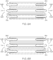
- FIG. 6A illustrates maneuverability options associated with the RWD mode, the FWD mode, and the MWD mode as described herein.
- the wheelchair assembly 300 movements include a distal movement (e.g., in the "D” direction as depicted in FIG. 6A ), a proximal movement (e.g., in the "P” direction as depicted in FIG. 6A ), a combination of distal and lateral movement (e.g., in the "D+ LD1" direction and/or the "D+LD2" direction as depicted in FIG.
- proximal and lateral movement e.g., in the "P+ LD1" direction and/or the "P+LD2" direction as depicted in FIG. 6A
- a pure lateral movement e.g., in the "LD1” and/or the "LD2" direction as depicted in FIG. 6B
- distal movement e.g., in the "D" direction as depicted in FIG.
- a proximal movement e.g., in the "P” direction as depicted in FIG. 6A
- a combination of distal and lateral movement e.g., in the "D+ LD1" direction and/or the "D+LD2" direction as depicted in FIG. 6A
- a combination of proximal and lateral movement e.g., in the "P+ LD1" direction and/or the "P+LD2" direction as depicted in FIG. 6A
- a pure lateral movement e.g., in the "LD1" and/or the "LD2" direction as depicted in FIG.
- the wheelchair assembly 300 movements include a distal movement (e.g., in the "D” direction as depicted in FIG. 6A ), a proximal movement (e.g., in the "P” direction as depicted in FIG. 6A ), a combination of distal and lateral movement (e.g., in the "D+ LD1" direction and/or the "D+LD2" direction as depicted in FIG.
- proximal and lateral movement e.g., in the "P+ LD1" direction and/or the "P+LD2" direction as depicted in FIG. 6A
- proximal and lateral movement e.g., in the "P+ LD1" direction and/or the "P+LD2" direction as depicted in FIG. 6A
- the standard wheels 314, 354 remain in contact with the surface.
- a pure lateral movement e.g., in the "LD1" and/or the "LD2" direction as depicted in FIG. 6B
- distal or proximal movement is not possible.
- FIG. 6B illustrates increased maneuverability options associated with the OWD mode as described herein.
- a pure lateral movement e.g., in the "LD1" and/or the "LD2" direction as depicted in FIG. 6B
- any of the knee wheels 316, 336, 356 and/or the foot wheel 334 may be driving omni-directional wheels such that wheelchair assembly 300 movements include a distal movement (e.g., in the "D" direction as depicted in FIG.
- a proximal movement e.g., in the "P” direction as depicted in FIG. 6B
- a combination of distal and lateral movement e.g., in the "D+ LD1" direction and/or the "D+LD2" direction as depicted in FIG. 6B
- a combination of proximal and lateral movement e.g., in the "P+ LD1" direction and/or the "P+LD2" direction as depicted in FIG. 6B
- a pure first lateral movement e.g., in the "LD1" direction as depicted in FIG.
- the knee wheels 316, 336a, 336b and/or 356 may be driving omni-directional wheels such that wheelchair assembly 300 movements include a distal movement (e.g., in the "D" direction as depicted in FIG. 6B ), a proximal movement (e.g., in the "P” direction as depicted in FIG. 6B ), a combination of distal and lateral movement (e.g., in the "D+ LD1" direction and/or the "D+LD2" direction as depicted in FIG. 6B ), a combination of proximal and lateral movement (e.g., in the "P+ LD1" direction and/or the "P+LD2" direction as depicted in FIG.
- a pure first lateral movement e.g., in the "LD1" direction as depicted in FIG. 6B
- a pure second lateral movement e.g., in the "LD2" direction as depicted in FIG. 6B .
- a standard wheel may include any wheel configured to move in a forward or distal "D” direction and/or a reverse or proximal "P" direction (e.g., a uni-directional wheel, a bi-directional wheel, or the like).
- Standard wheels as utilized herein, generally do not move in a lateral direction (e.g., in an "LD1" or "LD2" direction depicted herein) without overcoming frictional forces between the standard wheel and a surface.
- an omni-directional wheel may include a mecanum wheel, an omni-wheel, a caster, and/or the like.
- An omni-directional wheel enables omni-directional movement of the wheelchair assembly as described herein.
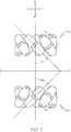
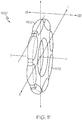
- FIG. 7 illustrates a top-down view of example mecanum wheels 702, 708.
- the first mecanum wheel 702 includes a plurality of rollers 704 rotatably coupled at an angle 706 (e.g., 45°), relative to axis F-F, around a circumference of the first mecanum wheel 702.
- Each of the plurality of rollers 704 translate a portion of the rotational force of the first mecanum wheel 702 to a normal force perpendicular to the first mecanum wheel 702 direction.
- the second mecanum wheel 708 includes a plurality of rollers 710 rotatably coupled at an angle 712 (e.g., 45°), relative to axis F-F, around a circumference of the second mecanum wheel 708.
- Each of the plurality of rollers 710 translate a portion of the rotational force of the second mecanum wheel 708 to a normal force perpendicular to the second mecanum wheel 708 direction.
- second mecanum wheel 708 a portion of a forward or distal "D" force is translated to an inward or second lateral "LD2" force and a portion of a reverse or proximal "P" force is translated to a first lateral "LD1" force.
- the second mecanum wheel 708 is a mirror version, about axis E-E, of the first mecanum wheel 702.
- mecanum wheels 702, 708 may each include a plurality of rollers rotatably coupled at a different angle (i.e., other than 45°) relative to axis F-F.
- the second mecanum wheel 708 is a mirror version, about axis E-E, of the first mecanum wheel 702.
- One or more pairs of mecanum wheels may be utilized to realize desired movements of a wheelchair assembly.
- a combination of mecanum wheels may be positioned and rotatable to produce a resulting force vector to move a wheelchair assembly coupled thereto in a desired direction. More specifically each mecanum wheel may rotate in a certain direction and/or with a certain speed to move the wheelchair assembly in a desired direction.
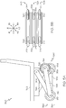
- FIG. 8 illustrates a first mecanum wheel 802 positioned at knee joint 318 of the lower leg assembly 308 and a second mecanum wheel 808 positioned at knee joint 358 of lower leg assembly 348.
- the first mecanum wheel 802 and the second mecanum wheel 808 may not be driven by a motor (e.g., may operate passively, may act as a caster, and/or the like).
- the first mecanum wheel 802 and the second mecanum wheel 808 may also be driven.
- the first mecanum wheel 802 and the second mecanum wheel 808 may rotate in a forward or distal "D” direction at an equal speed to aid the foot wheels 314, 354 (e.g., rotating in a forward or distal "D” direction) in propelling/driving the wheelchair assembly in the "D" direction.
- the first mecanum wheel 802 may rotate in a forward or distal "D” direction at a first speed and the second mecanum wheel 808 may rotate in a forward or distal "D” direction at a second speed slower than the first speed to aid the foot wheel 314 (e.g., rotating in a forward or distal "D” direction at a third speed) and the foot wheel 354 (e.g., rotating in a forward or distal "D” direction at a fourth speed slower than the third speed) in propelling/driving the wheelchair assembly in the "D + LD1" direction.
- the foot wheel 314 e.g., rotating in a forward or distal "D” direction at a third speed
- the foot wheel 354 e.g., rotating in a forward or distal "D” direction at a fourth speed slower than the third speed
- the first mecanum wheel 802 may rotate in a forward or distal "D” direction at a first speed and the second mecanum wheel 808 may rotate in a forward or distal "D” direction at a second speed faster than the first speed to aid the foot wheel 314 (e.g., rotating in a forward or distal "D” direction at a third speed) and the foot wheel 354 (e.g., rotating in a forward or distal "D” direction at a fourth speed slower than the third speed) in propelling/driving the wheelchair assembly in the "D + LD2" direction.
- the foot wheel 314 e.g., rotating in a forward or distal "D” direction at a third speed
- the foot wheel 354 e.g., rotating in a forward or distal "D” direction at a fourth speed slower than the third speed
- the first mecanum wheel 802 and the second mecanum wheel 808 may rotate in a reverse or proximal "P” direction at an equal speed to aid the foot wheels 314, 354 (e.g., rotating in a reverse or proximal "P” direction) in propelling/driving the wheelchair assembly in the "P" direction.
- the first mecanum wheel 802 may rotate in a reverse or proximal "P” direction at a first speed and the second mecanum wheel 808 may rotate in a reverse or proximal "P” direction at a second speed slower than the first speed to aid the foot wheel 314 (e.g., rotating in a reverse or proximal "P” direction at a third speed) and the foot wheel 354 (e.g., rotating in reverse or proximal "P” direction at a fourth speed slower than the third speed) in propelling/driving the wheelchair assembly in the "P + LD1" direction.
- the foot wheel 314 e.g., rotating in a reverse or proximal "P” direction at a third speed
- the foot wheel 354 e.g., rotating in reverse or proximal "P” direction at a fourth speed slower than the third speed
- the first mecanum wheel 802 may rotate in a reverse or proximal "P” direction at a first speed and the second mecanum wheel 808 may rotate in reverse or proximal "P” direction at a second speed faster than the first speed to aid the foot wheel 314 (e.g., rotating in reverse or proximal "P” direction at a third speed) and the foot wheel 354 (e.g., rotating in reverse or proximal "P” direction at a fourth speed faster than the third speed) in propelling/driving the wheelchair assembly in the "P + LD2" direction.
- the foot wheel 314 e.g., rotating in reverse or proximal "P” direction at a third speed
- the foot wheel 354 e.g., rotating in reverse or proximal "P” direction at a fourth speed faster than the third speed
- the first mecanum wheel 802 and the second mecanum wheel 808 may similarly drive the wheelchair assembly in the "D”, “D + LD1", “D + LD2", “P”, “P + LD1” and “P + LD2" directions, as discussed herein, while the foot wheels 314, 354 rotate in a passive manner.
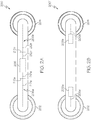
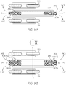
- FIG. 9A illustrates a first mecanum wheel 902b positioned at knee joint 338 of the lower leg assembly 328 and a first mecanum wheel 902a positioned at foot joint 340 of lower leg assembly 328.
- first mecanum wheel 902b at knee joint 338 nor the first mecanum wheel 902a at foot joint 340 may be driven (e.g., may operate passively, may act as a caster, and/or the like).
- the foot wheel 314 and the foot wheel 354 may rotate in a forward or distal "D” direction at an equal speed to propel/drive the wheelchair assembly in the "D” direction while the first mecanum wheel 902b at knee joint 338 and the first mecanum wheel 902a at foot joint 340 operate passively.
- the first mecanum wheel 902a positioned at foot joint 340 may rotate in a forward or distal "D” direction and the first mecanum wheel 902b positioned at knee joint 338 may operate passively to aid the foot wheel 314 (e.g., rotating in a forward or distal "D” direction at a first speed) and the foot wheel 354 (e.g., rotating in a forward or distal "D” direction at a second speed slower than the first speed) in propelling/driving the wheelchair assembly in the "D + LD1" direction.
- the foot wheel 314 e.g., rotating in a forward or distal "D” direction at a first speed
- the foot wheel 354 e.g., rotating in a forward or distal "D” direction at a second speed slower than the first speed
- the first mecanum wheel 902a positioned at foot joint 340 may operate passively and the first mecanum wheel 902b positioned at knee joint 338 may rotate in a forward or distal "D" direction to aid the foot wheel 314 (e.g., rotating in a forward or distal "D” direction at a first speed) and the foot wheel 354 (e.g., rotating in a forward or distal "D” direction at a second speed faster than the first speed) in propelling/driving the wheelchair assembly in the "D + LD2" direction.
- the foot wheel 314 e.g., rotating in a forward or distal "D” direction at a first speed
- the foot wheel 354 e.g., rotating in a forward or distal "D” direction at a second speed faster than the first speed
- the foot wheel 314 and the foot wheel 354 may rotate in a reverse or proximal "P" direction at an equal speed to propel/drive the wheelchair assembly in the "P” direction while the first mecanum wheel 902b at knee joint 338 and the first mecanum wheel 902a at foot joint 340 operate passively.
- the first mecanum wheel 902a positioned at foot joint 340 may rotate in reverse or proximal "P" direction and the first mecanum wheel 902b positioned at knee joint 338 may operate passively to aid the foot wheel 314 (e.g., rotating in a reverse or proximal "P” direction at a first speed) and the foot wheel 354 (e.g., rotating in a reverse or proximal "P” direction at a second speed slower than the first speed) in propelling/driving the wheelchair assembly in the "P + LD1" direction.
- the foot wheel 314 e.g., rotating in a reverse or proximal "P” direction at a first speed
- the foot wheel 354 e.g., rotating in a reverse or proximal "P” direction at a second speed slower than the first speed
- the first mecanum wheel 902a positioned at foot joint 340 may operate passively and the first mecanum wheel 902b positioned at knee joint 338 may rotate in a reverse or proximal "P" direction to aid the foot wheel 314 (e.g., rotating in a reverse or proximal "P” direction at a first speed) and the foot wheel 354 (e.g., rotating in a reverse or proximal "P” direction at a second speed faster than the first speed) in propelling/driving the wheelchair assembly in the "P + LD2" direction.
- the foot wheel 314 e.g., rotating in a reverse or proximal "P” direction at a first speed
- the foot wheel 354 e.g., rotating in a reverse or proximal "P” direction at a second speed faster than the first speed
- both the first mecanum wheel 902b positioned at knee joint 338 of the lower leg assembly 328 and a first mecanum wheel 902a positioned at foot joint 340 of lower leg assembly 328 may be substituted with 908b and 908a respectively (mirror versions of 902b and 902a, similar to FIG. 7 ).
- the foot wheel 314 and the foot wheel 354 may rotate in a forward or distal "D" direction at an equal speed to propel/drive the wheelchair assembly in the "D" direction while the second mecanum wheel 908b at knee joint 338 and the second mecanum wheel 908a at foot joint 340 operate passively.
- the second mecanum wheel 908a positioned at foot joint 340 may operate passively and the second mecanum wheel 908b positioned at knee joint 338 may rotate in a forward or distal "D" direction to aid the foot wheel 314 (e.g., rotating in a forward or distal "D” direction at a first speed) and the foot wheel 354 (e.g., rotating in a forward or distal "D” direction at a second speed slower than the first speed) in propelling/driving the wheelchair assembly in the "D + LD1" direction.
- the foot wheel 314 e.g., rotating in a forward or distal "D” direction at a first speed
- the foot wheel 354 e.g., rotating in a forward or distal "D” direction at a second speed slower than the first speed
- the second mecanum wheel 908a positioned at foot joint 340 may rotate in a forward or distal "D” direction and the second mecanum wheel 908b positioned at knee joint 338 may operate passively to aid the foot wheel 314 (e.g., rotating in a forward or distal "D” direction at a first speed) and the foot wheel 354 (e.g., rotating in a forward or distal "D” direction at a second speed faster than the first speed) in propelling/driving the wheelchair assembly in the "D + LD2" direction.
- the foot wheel 314 and the foot wheel 354 may rotate in a reverse or proximal "P" direction at an equal speed to propel/drive the wheelchair assembly in the "P” direction while the second mecanum wheel 908b at knee joint 338 and the second mecanum wheel 908a at foot joint 340 operate passively.
- the second mecanum wheel 908a positioned at foot joint 340 may operate passively and the second mecanum wheel 908b positioned at knee joint 338 may rotate in reverse or proximal "P" direction to aid the foot wheel 314 (e.g., rotating in a reverse or proximal "P” direction at a first speed) and the foot wheel 354 (e.g., rotating in a reverse or proximal "P” direction at a second speed slower than the first speed) in propelling/driving the wheelchair assembly in the "P + LD1" direction.
- the foot wheel 314 e.g., rotating in a reverse or proximal "P” direction at a first speed
- the foot wheel 354 e.g., rotating in a reverse or proximal "P” direction at a second speed slower than the first speed
- the second mecanum wheel 908a positioned at foot joint 340 may rotate in a reverse or proximal "P" direction and the second mecanum wheel 908b positioned at knee joint 338 may operate passively to aid the foot wheel 314 (e.g., rotating in a reverse or proximal "P” direction at a first speed) and the foot wheel 354 (e.g., rotating in a reverse or proximal "P” direction at a second speed faster than the first speed) in propelling/driving the wheelchair assembly in the "P + LD2" direction.
- the foot wheel 314 e.g., rotating in a reverse or proximal "P” direction at a first speed
- the foot wheel 354 e.g., rotating in a reverse or proximal "P” direction at a second speed faster than the first speed
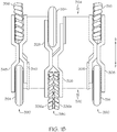
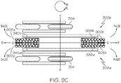
- FIG. 9B illustrates a first mecanum wheel 902b and a second mecanum wheel 908b positioned at knee joint 338 of the lower leg assembly 328 as well as a first mecanum wheel 902a and a second mecanum wheel 908a positioned at foot joint 340 of lower leg assembly 328.
- the mecanum wheels 902a, 902b, 908a, 908b are positioned such that they mirror each other not only about the G-G axis as depicted in FIG. 9B , but also about the H-H axis as depicted in FIG. 9B .
- each of the mecanum wheels may be selectively driven.
- the first mecanum wheel 902b and the second mecanum wheel 908b at the knee joint 338 as well as the first mecanum wheel 902a and the second mecanum wheel 908a at the foot joint 340 may rotate in a forward or distal "D" direction all at an equal speed to aid the foot wheels 314, 354 (e.g., rotating in a forward or distal "D” direction) in propelling/driving the wheelchair assembly in the "D" direction.
- the first mecanum wheel 902a at the foot joint 340 and the second mecanum wheel 908b at the knee joint 338 may rotate in a forward or distal "D" direction at a first speed and the second mecanum wheel 908a at the foot joint 340 and the first mecanum wheel 902b at the knee joint 338 may rotate in a forward or distal "D” direction at a second speed slower than the first speed to aid the foot wheel 314 (e.g., rotating in a forward or distal "D” direction at a third speed) and the foot wheel 354 (e.g., rotating in a forward or distal "D” direction at a fourth speed slower than the third speed) in propelling/driving the wheelchair assembly in the "D + LD1" direction.
- the foot wheel 314 e.g., rotating in a forward or distal "D” direction at a third speed
- the foot wheel 354 e.g., rotating in a forward or distal "D” direction at a fourth speed slower than the
- the second mecanum wheel 908a at the foot joint 340 and the first mecanum wheel 902b at the knee joint 338 may rotate in a forward or distal "D" direction at a first speed and the first mecanum wheel 902a at the foot joint 340 and the second mecanum wheel 908b at the knee joint 338 may rotate in a forward or distal "D” direction at a second speed slower than the first speed to aid the foot wheel 314 (e.g., rotating in a forward or distal "D” direction at a third speed) and the foot wheel 354 (e.g., rotating in a forward or distal "D” direction at a fourth speed faster than the third speed) in propelling/driving the wheelchair assembly in the "D + LD2" direction.
- the foot wheel 314 e.g., rotating in a forward or distal "D” direction at a third speed
- the foot wheel 354 e.g., rotating in a forward or distal "D” direction at a fourth speed faster than the
- the first mecanum wheel 902b and the second mecanum wheel 908b at the knee joint 338 as well as the first mecanum wheel 902a and the second mecanum wheel 908a at the foot joint 340 may rotate in a reverse or proximal "P" direction all at an equal speed to aid the foot wheels 314, 354 (e.g., rotating in a reverse or proximal "P” direction) in propelling/driving the wheelchair assembly in the "P" direction.
- the first mecanum wheel 902a at the foot joint 340 and the second mecanum wheel 908b at the knee joint 338 may rotate in a reverse or proximal "P" direction at a first speed and the second mecanum wheel 908a at the foot joint 340 and the first mecanum wheel 902b at the knee joint 338 may rotate in a reverse or proximal "P” direction at a second speed slower than the first speed to aid the foot wheel 314 (e.g., rotating in a reverse or proximal "P” direction at a third speed) and the foot wheel 354 (e.g., rotating in a reverse or proximal "P” direction at a fourth speed slower than the third speed) in propelling/driving the wheelchair assembly in the "P + LD1" direction.
- the foot wheel 314 e.g., rotating in a reverse or proximal "P” direction at a third speed
- the foot wheel 354 e.g., rotating in a reverse or proximal
- the second mecanum wheel 908a at the foot joint 340 and the first mecanum wheel 902b at the knee joint 338 may rotate in a reverse or proximal "P" direction at a first speed and the first mecanum wheel 902a at the foot joint 340 and the second mecanum wheel 908b at the knee joint 338 may rotate in a reverse or proximal "P” direction at a second speed slower than the first speed to aid the foot wheel 314 (e.g., rotating in a reverse or proximal "P” direction at a third speed) and the foot wheel 354 (e.g., rotating in a reverse or proximal "P” direction at a fourth speed faster than the third speed) in propelling/driving the wheelchair assembly in the "P + LD2" direction.
- the foot wheel 314 e.g., rotating in a reverse or proximal "P” direction at a third speed
- the foot wheel 354 e.g., rotating in a reverse or proximal
- the wheelchair assembly 300 is able to rotate or turn, in place, with a minimal or zero turning radius.
- a first direction e.g., rotate right RR
- the first mecanum wheel 902a at the foot joint 340 and the second mecanum wheel 908b at the knee joint 338 may rotate in a forward or distal "D" direction at a first speed
- the second mecanum wheel 908a at the foot joint 340 and the first mecanum wheel 902b at the knee joint 338 may rotate in a reverse or proximal "P" direction at a second speed equal to the first speed
- the foot wheel 314 rotates in a forward or distal "D" direction at a third speed
- the foot wheel 354 rotates in a reverse or proximal "P” direction at a fourth speed equal to the third speed to rotate the wheelchair assembly 300, in place, in the first direction (e.g.
- the first mecanum wheel 902a at the foot joint 340 and the second mecanum wheel 908b at the knee joint 338 may rotate in a reverse or proximal "P" direction at a first speed and the second mecanum wheel 908a at the foot joint 340 and the first mecanum wheel 902b at the knee joint 338 may rotate in a forward or distal "D" direction at a second speed equal to the first speed while the foot wheel 314 rotates in a reverse or proximal "P" direction at a third speed and the foot wheel 354 rotates in a forward or distal "D” direction at a fourth speed equal to the third speed to rotate the wheelchair assembly 300, in place, in the second direction (e.g. rotate left RL).
- a second direction e.g. rotate left RL
- the lower leg assembly 328 of FIG. 9B including the first mecanum wheel 902a and the second mecanum wheel 908a positioned at foot joint 340 and the first mecanum wheel 902b and the second mecanum wheel 908b positioned at knee joint 338 may be separated into a lower leg assembly 328a (e.g., including the first mecanum wheel 902a at foot joint 340a and the second mecanum wheel 908b at knee joint 338a) and a lower leg assembly 328b (e.g., including the second mecanum wheel 908a at foot joint 340b and the first mecanum wheel 902b at knee joint 338b).
- a lower leg assembly 328a e.g., including the first mecanum wheel 902a at foot joint 340a and the second mecanum wheel 908b at knee joint 338a
- a lower leg assembly 328b e.g., including the second mecanum wheel 908a at foot joint 340b and the first mecanum wheel 902b
- the lower leg assembly 328a may be part of a leg module 385a and the lower leg assembly 328b may be part of separate leg module 385b.
- embodiments including four leg modules 380, 385a, 385b, and 390 are contemplated by the present disclosure. Embodiments including more than four leg modules are also contemplated.
- at some point system inefficiencies e.g., weight of additional leg modules/components, drag/friction resulting from contact of additional wheels with a surface, and/or the like
- the wheelchair assembly 300 may be driven in some embodiments by an omni-directional foot wheel (see FIG. 5B , e.g., foot wheel 334 at foot joint 340) and an omni-directional knee wheel (see FIG. 5B , e.g., knee wheel 336 at knee joint 338).
- FIG. 10 substitutes the foot wheel 334 at foot joint 340 of the lower leg assembly 328 with a first mecanum wheel 1002a and a second mecanum wheel 1008a and substitutes the knee wheel 336 at knee joint 338 of the lower leg assembly 328 with a first mecanum wheel 1002b and a second mecanum wheel 1008b.
- FIG. 10 similar to FIGS.
- the mecanum wheels are positioned such that they mirror each other not only about the G-G axis as depicted in FIG. 10 , but also about the H-H axis as depicted in FIG. 10 .
- each of the mecanum wheels may be selectively driven to propel or move the wheelchair assembly 300.
- the wheelchair assembly 300 may be further driven by mecanum wheel 1016 (e.g., an omni-directional knee wheel) of the lower leg assembly 308 and mecanum wheel 1056 (e.g., an omni-directional knee wheel) of the lower leg assembly 348.
- only omni-directional wheels are in contact with the surface 364 (e.g., the foot wheel 1014 of the lower leg assembly 308 and the foot wheel 1054 of the lower leg assembly 348 are selectively raised off of the surface 364).
- the wheelchair assembly 300 may be driven by the mecanum wheel 1016 and the mecanum wheel 1056 while the first mecanum wheel 1002a and the second mecanum wheel 1008a at foot joint 340 and the first mecanum wheel 1002b and the second mecanum wheel 1008b at knee joint 338 operate passively (e.g., may act as a caster, and/or the like).
- the mecanum wheel 1016 and the mecanum wheel 1056 may rotate in a forward or distal "D" direction at an equal speed to propel/drive the wheelchair assembly 300 in the "D" direction.
- the mecanum wheel 1016 may rotate in a forward or distal "D” direction at a first speed and the mecanum wheel 1056 may rotate in a forward or distal “D” direction at a second speed slower than the first speed to propel/drive the wheelchair assembly 300 in the "D + LD1" direction.
- the mecanum wheel 1016 may rotate in a forward or distal "D” direction at a first speed and the second mecanum wheel 1056 may rotate in a forward or distal "D” direction at a second speed faster than the first speed to propel/drive the wheelchair assembly 300 in the "D + LD2" direction.
- the mecanum wheel 1016 and the mecanum wheel 1056 may rotate in a reverse or proximal "P” direction at an equal speed to propel/drive the wheelchair assembly 300 in the "P” direction.
- the mecanum wheel 1016 may rotate in a reverse or proximal "P” direction at a first speed and the mecanum wheel 1056 may rotate in a reverse or proximal "P” direction at a second speed slower than the first speed to propel/drive the wheelchair assembly 300 in the "P + LD1" direction.
- the mecanum wheel 1016 may rotate in a reverse or proximal "P” direction at a first speed and the mecanum wheel 1056 may rotate in reverse or proximal "P” direction at a second speed faster than the first speed to propel/drive the wheelchair assembly 300 in the "P + LD2" direction.
- the wheelchair assembly 300 may be driven by the first mecanum wheel 1002a and the second mecanum wheel 1008a at foot joint 340 and the first mecanum wheel 1002b and the second mecanum wheel 1008b at knee joint 338 while the mecanum wheel 1016 and the mecanum wheel 1056 operate passively (e.g., may act as a caster, and/or the like).
- the first mecanum wheel 1002a and the second mecanum wheel 1008a at the foot joint 340 as well as the first mecanum wheel 1002b and the second mecanum wheel 1008b at the knee joint 338 may rotate in a forward or distal "D" direction at an equal speed to propel/drive the wheelchair assembly 300 in the "D" direction.
- the first mecanum wheel 1002a at the foot joint 340 and the second mecanum wheel 1008b at the knee joint 338 may rotate in a forward or distal "D" direction at a first speed and the second mecanum wheel 1008a at the foot joint 340 and the first mecanum wheel 1002b at the knee joint 338 may rotate in a forward or distal "D” direction at a second speed slower than the first speed to propel/drive the wheelchair assembly 300 in the "D + LD1" direction.
- the second mecanum wheel 1008a at the foot joint 340 and the first mecanum wheel 1002b at the knee joint 338 may rotate in a forward or distal "D" direction at a first speed and the first mecanum wheel 1002a at the foot joint 340 and the second mecanum wheel 1008b at the knee joint 338 may rotate in a forward or distal "D” direction at a second speed slower than the first speed to propel/drive the wheelchair assembly 300 in the "D + LD2" direction.
- the first mecanum wheel 1002b and the second mecanum wheel 1008b at the knee joint 338 as well as the first mecanum wheel 1002a and the second mecanum wheel 1008a at the foot joint 340 may rotate in a reverse or proximal "P" direction at an equal speed to propel/drive the wheelchair assembly in the "P" direction.
- the first mecanum wheel 1002a at the foot joint 340 and the second mecanum wheel 1008b at the knee joint 338 may rotate in a reverse or proximal "P" direction at a first speed and the second mecanum wheel 1008a at the foot joint 340 and the first mecanum wheel 1002b at the knee joint 338 may rotate in a reverse or proximal "P” direction at a second speed slower than the first speed to propel/drive the wheelchair assembly 300 in the "P + LD1" direction.
- the second mecanum wheel 1008a at the foot joint 340 and the first mecanum wheel 1002b at the knee joint 338 may rotate in a reverse or proximal "P" direction at a first speed and the first mecanum wheel 1002a at the foot joint 340 and the second mecanum wheel 1008b at the knee joint 338 may rotate in a reverse or proximal "P” direction at a second speed slower than the first speed to propel/drive the wheelchair assembly 300 in the "P + LD2" direction.
- omni-directional wheels e.g., mecanum wheels
- LD1 and LD2 movement may also be realized.
- the first mecanum wheel 1002 at the foot joint 340 and the first mecanum wheel 1002b at the knee joint 338 may rotate in a forward or distal "D" direction at a first speed while the second mecanum wheel 1008a at the foot joint 340 and the second mecanum wheel 1008b at the knee joint 338 rotate in a reverse or proximal "P" direction at a second speed equal to the first speed to propel/drive the wheelchair assembly 300 in the LD1 direction.
- the first mecanum wheel 1002a at the foot joint 340 and the first mecanum wheel 1002b at the knee joint 338 may rotate in a reverse or proximal "P" direction at a first speed while the second mecanum wheel 1008a at the foot joint 340 and the second mecanum wheel 1008b at the knee joint 338 rotate in a forward or distal "D" direction at a second speed equal to the first speed to propel/drive the wheelchair assembly 300 in the LD2 direction.
- the wheelchair assembly 300 is able to rotate or turn, in place, with a minimal or zero turning radius.
- the first mecanum wheel 1002a at the foot joint 340 and the second mecanum wheel 1008b at the knee joint 338 may rotate in a forward or distal "D" direction at a first speed and the second mecanum wheel 1008a at the foot joint 340 and the first mecanum wheel 1002b at the knee joint 338 may rotate in a reverse or proximal "P" direction at a second speed equal to the first speed to rotate the wheelchair assembly 300, in place, in the first direction (e.g. rotate right RR).
- the first mecanum wheel 1002a at the foot joint 340 and the second mecanum wheel 1008b at the knee joint 338 may rotate in a reverse or proximal "P" direction at a first speed and the second mecanum wheel 1008a at the foot joint 340 and the first mecanum wheel 1002b at the knee joint 338 may rotate in a forward or distal "D" direction at a second speed equal to the first speed to rotate the wheelchair assembly 300, in place, in the second direction (e.g. rotate left RL).
- the wheelchair assembly 300 may be driven by the first mecanum wheel 1002a and the second mecanum wheel 1008a at foot joint 340, the first mecanum wheel 1002b and the second mecanum wheel 1008b at knee joint 338, the mecanum wheel 1016, and the mecanum wheel 1056.
- the first mecanum wheel 1002a and the second mecanum wheel 1008a at the foot joint 340, the first mecanum wheel 1002b and the second mecanum wheel 1008b at the knee joint 338, the mecanum wheel 1016, and the mecanum wheel 1056 may rotate in a forward or distal "D" direction at an equal speed to propel/drive the wheelchair assembly 300 in the "D" direction.
- the first mecanum wheel 1002a at the foot joint 340, the second mecanum wheel 1008b at the knee joint 338, and the mecanum wheel 1016 may rotate in a forward or distal "D” direction at a first speed and the second mecanum wheel 1008a at the foot joint 340, the first mecanum wheel 1002b at the knee joint 338, and the mecanum wheel 1056 may rotate in a forward or distal "D” direction at a second speed slower than the first speed to propel/drive the wheelchair assembly 300 in the "D + LD1" direction.
- the first mecanum wheel 1002a at the foot joint 340 and the second mecanum wheel 1008b at the knee joint 338 may rotate in a forward or distal "D" direction at a first speed and the second mecanum wheel 1008a at the foot joint 340 and the first mecanum wheel 1002b at the knee joint 338 may rotate in a forward or distal "D” direction at a second speed slower than the first speed while the mecanum wheel 1016 and mecanum wheel 1056 rotate in a forward or distal "D” direction at an equal speed to propel/drive the wheelchair assembly 300 in the "D + LD1" direction.
- the second mecanum wheel 1008a at the foot joint 340, the first mecanum wheel 1002b at the knee joint 338, and the mecanum wheel 1056 may rotate in a forward or distal "D” direction at a first speed and the first mecanum wheel 1002a at the foot joint 340, the second mecanum wheel 1008b at the knee joint 338, and the mecanum wheel 1016 may rotate in a forward or distal "D” direction at a second speed slower than the first speed to propel/drive the wheelchair assembly 300 in the "D + LD2" direction.
- the second mecanum wheel 1008a at the foot joint 340 and the first mecanum wheel 1002b at the knee joint 338 may rotate in a forward or distal "D" direction at a first speed and the first mecanum wheel 1002a at the foot joint 340 and the second mecanum wheel 1008b at the knee joint 338 may rotate in a forward or distal "D” direction at a second speed slower than the first speed while the mecanum wheel 1016 and mecanum wheel 1056 rotate in a forward or distal "D” direction at an equal speed to propel/drive the wheelchair assembly 300 in the "D + LD2" direction.
- the first mecanum wheel 1002b and the second mecanum wheel 1008b at the knee joint 338, the first mecanum wheel 1002a and the second mecanum wheel 1008a at the foot joint 340, the mecanum wheel 1016 and the mecanum wheel 1056 may rotate in a reverse or proximal "P" direction at an equal speed to propel/drive the wheelchair assembly in the "P" direction.
- the first mecanum wheel 1002a at the foot joint 340, the second mecanum wheel 1008b at the knee joint 338, and the mecanum wheel 1016 may rotate in a reverse or proximal "P" direction at a first speed and the second mecanum wheel 1008a at the foot joint 340, the first mecanum wheel 1002b at the knee joint 338, and the mecanum wheel 1056 may rotate in a reverse or proximal "P" direction at a second speed slower than the first speed to propel/drive the wheelchair assembly 300 in the "P + LD1" direction.
- the first mecanum wheel 1002a at the foot joint 340 and the second mecanum wheel 1008b at the knee joint 338 may rotate in a reverse or proximal "P" direction at a first speed and the second mecanum wheel 1008a at the foot joint 340 and the first mecanum wheel 1002b at the knee joint 338 may rotate in a reverse or proximal "P” direction at a second speed slower than the first speed while the mecanum wheel 1016 and the mecanum wheel 1056 rotate in a reverse or proximal "P” direction at an equal speed to propel/drive the wheelchair assembly 300 in the "P + LD1" direction.
- the second mecanum wheel 1008a at the foot joint 340, the first mecanum wheel 1002b at the knee joint 338, and the mecanum wheel 1056 may rotate in a reverse or proximal "P" direction at a first speed and the first mecanum wheel 1002a at the foot joint 340, the second mecanum wheel 1008b at the knee joint 338, and the mecanum wheel 1016 may rotate in a reverse or proximal "P" direction at a second speed slower than the first speed to propel/drive the wheelchair assembly 300 in the "P + LD2" direction.
- the second mecanum wheel 1008a at the foot joint 340 and the first mecanum wheel 1002b at the knee joint 338 may rotate in a reverse or proximal "P" direction at a first speed and the first mecanum wheel 1002a at the foot joint 340 and the second mecanum wheel 1008b at the knee joint 338 may rotate in a reverse or proximal "P” direction at a second speed slower than the first speed while the mecanum wheel 1016 and the mecanum wheel 1056 rotate in a reverse or proximal "P” direction at an equal speed to propel/drive the wheelchair assembly 300 in the "P + LD2" direction.
- the first mecanum wheel 1002a at the foot joint 340, the first mecanum wheel 1002b at the knee joint 338, and the mecanum wheel 1016 may rotate in a forward or distal "D" direction at a first speed while the second mecanum wheel 1008a at the foot joint 340, the second mecanum wheel 1008b at the knee joint 338, and the mecanum wheel 1056 rotate in a reverse or proximal "P" direction at a second speed equal to the first speed to propel/drive the wheelchair assembly 300 in the LD1 direction.
- the first mecanum wheel 1002a at the foot joint 340, the first mecanum wheel 1002b at the knee joint 338, and the mecanum wheel 1016 may rotate in a reverse or proximal "P" direction at a first speed while the second mecanum wheel 1008a at the foot joint 340, the second mecanum wheel 1008b at the knee joint 338, and the mecanum wheel 1056 rotate in a forward or distal "D" direction at a second speed equal to the first speed to propel/drive the wheelchair assembly 300 in the LD2 direction.
- the wheelchair assembly 300 is able to rotate or turn, in place, with a minimal or zero turning radius.
- the first mecanum wheel 1002a at the foot joint 340 and the second mecanum wheel 1008b at the knee joint 338 may rotate in a forward or distal "D" direction at a first speed and the second mecanum wheel 1008a at the foot joint 340 and the first mecanum wheel 1002b at the knee joint 338 may rotate in a reverse or proximal "P" direction at a second speed equal to the first speed while the mecanum wheel 1016 rotates in a forward or distal "D" direction at a third speed and the mecanum wheel 1056 rotates in a reverse or proximal "P" direction at a fourth speed equal to the third speed to rotate the wheelchair assembly 300, in place, in the first direction (e.g., rotate right RR)
- the first mecanum wheel 1002a at the foot joint 340 and the second mecanum wheel 1008b at the knee joint 338 may rotate in a forward or distal "D" direction at a first speed
- the first mecanum wheel 1002a at the foot joint 340 and the second mecanum wheel 1008b at the knee joint 338 may rotate in a reverse or proximal "P" direction at a first speed and the second mecanum wheel 1008a at the foot joint 340 and the first mecanum wheel 1002b at the knee joint 338 may rotate in a forward or distal "D" direction at a second speed equal to the first speed while the mecanum wheel 1016 rotates in a reverse or proximal "P" direction at a third speed and the mecanum wheel 1056 rotates in a forward or distal "D” direction at a fourth speed equal to the third speed to rotate the wheelchair assembly 300, in place, in the second direction (e.g. rotate left RL).
- a second direction e.g. rotate left RL
- the first mecanum wheel 1002a and the second mecanum wheel 1008a at the foot joint 340 may be selectively raised off of the surface 364. In such an aspect, only omni-directional wheels would remain in contact with the surface 364. According to such an aspect, to realize "D" movement, the first mecanum wheel 1002b and the second mecanum wheel 1008b at the knee joint 338, the mecanum wheel 1016, and the mecanum wheel 1056 may rotate in a forward or distal "D" direction at an equal speed to propel/drive the wheelchair assembly 300 in the "D" direction.
- the mecanum wheel 1016 and the second mecanum wheel 1008b at the knee joint 338 may rotate in a forward or distal "D” direction at a first speed and the mecanum wheel 1056 and the first mecanum wheel 1002b at the knee joint 338 may rotate in a forward or distal "D” direction at a second speed slower than the first speed to propel/drive the wheelchair assembly 300 in the "D + LD1" direction.
- the mecanum wheel 1056 and the first mecanum wheel 1002b at the knee joint 338 may rotate in a forward or distal "D” direction at a first speed and the mecanum wheel 1016 and the second mecanum wheel 1008b at the knee joint 338 may rotate in a forward or distal "D” direction at a second speed slower than the first speed to propel/drive the wheelchair assembly 300 in the "D + LD2" direction.
- the first mecanum wheel 1002b and the second mecanum wheel 1008b at the knee joint 338, the mecanum wheel 1016, and the mecanum wheel 1056 may rotate in a reverse or proximal "P" direction at an equal speed to propel/drive the wheelchair assembly in the "P" direction.
- the mecanum wheel 1016 and the second mecanum wheel 1008b at the knee joint 338 may rotate in a reverse or proximal "P" direction at a first speed and the mecanum wheel 1056 and the first mecanum wheel 1002b at the knee joint 338 may rotate in a reverse or proximal "P” direction at a second speed slower than the first speed to propel/drive the wheelchair assembly 300 in the "P + LD1" direction.
- the mecanum wheel 1056 and the first mecanum wheel 1002b at the knee joint 338 may rotate in a reverse or proximal "P" direction at a first speed and the mecanum wheel 1016 and the second mecanum wheel 1008b at the knee joint 338 may rotate in a reverse or proximal "P” direction at a second speed slower than the first speed to propel/drive the wheelchair assembly 300 in the "P + LD2" direction.
- omni-directional wheels e.g., mecanum wheels
- LD1 and LD2 movement may also be realized.
- the mecanum wheel 1016 and the first mecanum wheel 1002b at the knee joint 338 may rotate in a forward or distal "D" direction at a first speed while the mecanum wheel 1056 and the second mecanum wheel 1008b at the knee joint 338 rotate in a reverse or proximal "P" direction at a second speed equal to the first speed to propel/drive the wheelchair assembly 300 in the LD1 direction.
- the mecanum wheel 1016 and the first mecanum wheel 1002b at the knee joint 338 may rotate in a reverse or proximal "P" direction at a first speed while the mecanum wheel 1056 and the second mecanum wheel 1008b at the knee joint 338 rotate in a forward or distal "D" direction at a second speed equal to the first speed to propel/drive the wheelchair assembly 300 in the LD2 direction.
- the wheelchair assembly 300 is able to rotate or turn, in place, with a minimal or zero turning radius.
- the mecanum wheel 1016 and the second mecanum wheel 1008b at the knee joint 338 may rotate in a forward or distal "D" direction at a first speed and the mecanum wheel 1056 and the first mecanum wheel 1002b at the knee joint 338 may rotate in a reverse or proximal "P" direction at a second speed equal to the first speed to rotate the wheelchair assembly 300, in place, in the first direction (e.g. rotate right RR).
- the mecanum wheel 1016 and the second mecanum wheel 1008b at the knee joint 338 may rotate in a reverse or proximal "P" direction at a first speed and the mecanum wheel 1056 and the first mecanum wheel 1002b at the knee joint 338 may rotate in a forward or distal "D" direction at a second speed equal to the first speed to rotate the wheelchair assembly 300, in place, in the second direction (e.g. rotate left RL).
- the movements of such an aspect similarly apply to an embodiment where the first mecanum wheel 1002a and the second mecanum wheel 1008a at the foot joint 340 are substituted with a standard wheel (e.g., see FIG. 1B ).
- the lower leg assembly 328 of FIG. 10 including the first mecanum wheel 1002a and the second mecanum wheel 1008a positioned at foot joint 340 and the first mecanum wheel 1002b and the second mecanum wheel 1008b positioned at knee joint 338 may be separated into a lower leg assembly 328a (e.g., including the first mecanum wheel 1002a at foot joint 340a and the second mecanum wheel 1008b at knee joint 338a) and a lower leg assembly 328b (e.g., including the second mecanum wheel 1008a at foot joint 340b and the first mecanum wheel 1002b at knee joint 338b).
- a lower leg assembly 328a e.g., including the first mecanum wheel 1002a at foot joint 340a and the second mecanum wheel 1008b at knee joint 338a
- a lower leg assembly 328b e.g., including the second mecanum wheel 1008a at foot joint 340b and the first mecanum wheel 1002b at
- the lower leg assembly 328a may be part of a leg module 385a and the lower leg assembly 328b may be part of separate leg module 385b.
- embodiments including four leg modules 380, 385a, 385b, and 390 are contemplated by the present disclosure. Embodiments including more than four leg modules are also contemplated.
- An omni-directional wheel may alternatively include an omni-wheel 1100 as illustrated in FIG. 11 .
- an omni-wheel 1100 may include a plurality of rollers 1102 rotatably coupled around a circumference of the omni-wheel 1100.
- Each of the plurality of rollers 1102 may be coupled to the circumference of the omni-wheel 1100 such that an axis of rotation of each roller 1102 (e.g., axis I-I) is perpendicular to the axis of rotation of the omni-wheel (e.g., axis J-J).
- rotation of the plurality of rollers 1102 permit movement of the omni-wheel 1100 (e.g., and components coupled thereto) in a first lateral "LD1" direction and a second lateral "LD2" direction, as depicted in FIG. 11 .
- the plurality of rollers 1102 are also rotatable about the axis of rotation of the omni-wheel (e.g., axis J-J) to realize movement in a distal "D" direction and a proximal "P" direction, as depicted in FIG. 11 .
- each roller 1102 may be selectively and independently driven (e.g., via motor(s), drive shaft(s), and/or the like) to move in the first lateral "LD1" direction and the second lateral "LD2" direction as depicted in FIG. 11 .
- each roller may not be selectively and independently driven (e.g., may operate passively, may act as a caster, and/or the like) to move in the first lateral "LD1" direction and the second lateral "LD2" direction as depicted in FIG. 11 .
- the each roller 1102 may be selectively and independently driven while other of the rollers 1102 may not be selectively and independently driven to move in the first lateral "LD1" direction and the second lateral "LD2" direction.
- the each roller 1102 may be selectively rotatable (e.g., at any angle) about an axis (e.g., axis K-K) perpendicular to its axis of rotation (e.g., axis I-I) to mimic a mecanum wheel (e.g., see FIG. 7 ), to mimic a caster (e.g., active or passive) and/or to realize movement in any selectable direction.
- an axis e.g., axis K-K
- axis I-I perpendicular to its axis of rotation
- mecanum wheel e.g., see FIG. 7
- a caster e.g., active or passive
- FIG. 12 illustrates a first omni-wheel 1202 positioned at knee joint 318 of the lower leg assembly 308 and a second omni-wheel 1208 positioned at knee joint 358 of lower leg assembly 348.
- the first omni-wheel 1202 and the second omni-wheel 1208 may not be driven by a motor (e.g., may operate passively, may act as a caster, and/or the like).
- the first omni-wheel 1202 and the second omni-wheel 1208 may also be driven.
- the first omni-wheel 1202 and the second omni-wheel 1208 may rotate in a forward or distal "D” direction at an equal speed to aid the foot wheels 314, 354 (e.g., rotating in a forward or distal "D” direction) in propelling/driving the wheelchair assembly in the "D" direction.
- first rollers 1204 of the first omni-wheel 1202 and second rollers 1206 of the second omni-wheel 1208 may not rotate.
- the first rollers 1204 of the first omni-wheel 1202 may rotate in an "LD1" direction and the second rollers 1206 of the second omni-wheel 1208 may rotate in an "LD1" direction to aid the foot wheel 314 (e.g., rotating in a forward or distal "D” direction at a first speed) and the foot wheel 354 (e.g., rotating in a forward or distal "D” direction at a second speed slower than the first speed) in propelling/driving the wheelchair assembly in the "D + LD1" direction.
- the first omni-wheel 1202 may rotate in a forward or distal "D" direction at a third speed and the second omni-wheel 1208 may rotate in a forward or distal "D” direction at a fourth speed slower than the third speed to further aid the foot wheel 314 and the foot wheel 354 in propelling/driving the wheelchair assembly in the "D + LD1" direction.
- the first rollers 1204 of the first omni-wheel 1202 may rotate in an "LD2" direction and the second rollers 1206 of the second omni-wheel 1208 may rotate in an "LD2" direction to aid the foot wheel 314 (e.g., rotating in a forward or distal "D” direction at a first speed) and the foot wheel 354 (e.g., rotating in a forward or distal "D” direction at a second speed faster than the first speed) in propelling/driving the wheelchair assembly in the "D + LD1" direction.
- the first omni-wheel 1202 may rotate in a forward or distal "D” direction at a third speed and the second omni-wheel 1208 may rotate in a forward or distal "D” direction at a fourth speed faster than the third speed to further aid the foot wheel 314 and the foot wheel 354 in propelling/driving the wheelchair assembly in the "D + LD2" direction.
- the first omni-wheel 1202 and the second omni-wheel 1208 may rotate in a reverse or proximal "P” direction at an equal speed to aid the foot wheels 314, 354 (e.g., rotating in a reverse or proximal "P” direction) in propelling/driving the wheelchair assembly in the "P" direction.
- first rollers 1204 of the first omni-wheel 1202 and second rollers 1206 of the second omni-wheel 1208 may not rotate.
- the first rollers 1204 of the first omni-wheel 1202 may rotate in an "LD2" direction and the second rollers 1206 of the second omni-wheel 1208 may rotate in an "LD2" direction to aid the foot wheel 314 (e.g., rotating in a reverse or proximal "P" direction at a first speed) and the foot wheel 354 (e.g., rotating in a reverse or proximal "P” direction at a second speed slower than the first speed) in propelling/driving the wheelchair assembly in the "P + LD1" direction.
- the first omni-wheel 1202 may rotate in a reverse or proximal "P" direction at a third speed and the second omni-wheel 1208 may rotate in a reverse or proximal "P” direction at a fourth speed slower than the third speed to further aid the foot wheel 314 and the foot wheel 354 in propelling/driving the wheelchair assembly in the "P + LD1" direction.
- the first rollers 1204 of the first omni-wheel 1202 may rotate in an "LD1" direction and the second rollers 1206 of the second omni-wheel 1208 may rotate in an "LD1" direction to aid the foot wheel 314 (e.g., rotating in a reverse or proximal "P” direction at a first speed) and the foot wheel 354 (e.g., rotating in a reverse or proximal "P” direction at a second speed faster than the first speed) in propelling/driving the wheelchair assembly in the "P + LD2" direction.
- the foot wheel 314 e.g., rotating in a reverse or proximal "P” direction at a first speed
- the foot wheel 354 e.g., rotating in a reverse or proximal "P” direction at a second speed faster than the first speed
- the first omni-wheel 1202 may rotate in a reverse or proximal "P" direction at a third speed and the second omni-wheel 1208 may rotate in a reverse or proximal "P” direction at a fourth speed faster than the third speed to further aid the foot wheel 314 and the foot wheel 354 in propelling/driving the wheelchair assembly in the "P + LD1" direction.
- the first omni-wheel 1202 and the second omni-wheel 1208 may similarly drive the wheelchair assembly in the "D", “D + LD1", “D + LD2", “P”, "P + LD1” and “P + LD2" directions, as discussed herein, while the foot wheels 314, 354 rotate in a passive manner.
- FIG. 13 illustrates a first omni-wheel 1302 positioned at knee joint 338 of the lower leg assembly 328 and a second omni-wheel 1308 positioned at foot joint 340 of lower leg assembly 328.
- first omni-wheel 1302 positioned at knee joint 338 of the lower leg assembly 328
- second omni-wheel 1308 positioned at foot joint 340 of lower leg assembly 328.
- neither the first omni-wheel 1302 nor the second omni-wheel 1308 may be driven (e.g., may operate passively, may act as a caster, and/or the like).
- the foot wheel 314 and the foot wheel 354 may rotate in a forward or distal "D” direction at an equal speed to propel/drive the wheelchair assembly in the "D" direction while the first omni-wheel 1302 and the second omni-wheel 1308 operate passively.
- the first omni-wheel 1302 and the second omni-wheel 1308 may also be driven.
- the first omni-wheel 1302 and the second omni-wheel 1308 may rotate in a forward or distal "D” direction at an equal speed to aid the foot wheels 314, 354 (e.g., rotating in a forward or distal "D” direction) in propelling/driving the wheelchair assembly in the "D" direction.
- first rollers 1304 of the first omni-wheel 1302 and second rollers 1306 of the second omni-wheel 1308 may not rotate.
- the first rollers 1304 of the first omni-wheel 1302 may rotate in an "LD2" direction and the second rollers 1306 of the second omni-wheel 1308 may rotate in an "LD1" direction to aid the foot wheel 314 (e.g., rotating in a forward or distal "D” direction at a first speed) and the foot wheel 354 (e.g., rotating in a forward or distal "D” direction at a second speed slower than the first speed) in propelling/driving the wheelchair assembly in the "D + LD1" direction.
- the first omni-wheel 1302 and the second omni-wheel 1308 may rotate in a forward or distal "D" direction at a third speed to further aid the foot wheel 314 and the foot wheel 354 in propelling/driving the wheelchair assembly in the "D + LD1" direction.
- the first rollers 1304 of the first omni-wheel 1302 may rotate in an "LD1" direction and the second rollers 1306 of the second omni-wheel 1308 may rotate in an "LD2" direction to aid the foot wheel 314 (e.g., rotating in a forward or distal "D” direction at a first speed) and the foot wheel 354 (e.g., rotating in a forward or distal "D” direction at a second speed faster than the first speed) in propelling/driving the wheelchair assembly in the "D + LD2" direction.
- the first omni-wheel 1302 and the second omni-wheel 1308 may rotate in a forward or distal "D" direction at a third speed to further aid the foot wheel 314 and the foot wheel 354 in propelling/driving the wheelchair assembly in the "D + LD2" direction.
- the foot wheel 314 and the foot wheel 354 may rotate in a reverse or proximal "P” direction at an equal speed to propel/drive the wheelchair assembly in the "P" direction while the first omni-wheel 1302 and the second omni-wheel 1308 operate passively.
- the first omni-wheel 1302 and the second omni-wheel 1308 may also be driven.
- the first omni-wheel 1302 and the second omni-wheel 1308 may rotate in a reverse or proximal "P" direction at an equal speed to aid the foot wheels 314, 354 (e.g., rotating in a reverse or proximal "P” direction) in propelling/driving the wheelchair assembly in the "P" direction.
- first rollers 1304 of the first omni-wheel 1302 and second rollers 1306 of the second omni-wheel 1308 may not rotate.
- the first rollers 1304 of the first omni-wheel 1302 may rotate in an "LD1" direction and the second rollers 1306 of the second omni-wheel 1308 may rotate in an "LD2" direction to aid the foot wheel 314 (e.g., rotating in a reverse or proximal "P” direction at a first speed) and the foot wheel 354 (e.g., rotating in a reverse or proximal "P” direction at a second speed slower than the first speed) in propelling/driving the wheelchair assembly in the "P + LD1" direction.
- the foot wheel 314 e.g., rotating in a reverse or proximal "P” direction at a first speed
- the foot wheel 354 e.g., rotating in a reverse or proximal "P” direction at a second speed slower than the first speed
- the first omni-wheel 1302 and the second omni-wheel 1308 may rotate in a reverse or proximal "P" direction at a third speed to further aid the foot wheel 314 and the foot wheel 354 in propelling/driving the wheelchair assembly in the "P + LD1" direction.
- the first rollers 1304 of the first omni-wheel 1302 may rotate in an "LD2" direction and the second rollers 1306 of the second omni-wheel 1308 may rotate in an "LD1" direction to aid the foot wheel 314 (e.g., rotating in a reverse or proximal "P” direction at a first speed) and the foot wheel 354 (e.g., rotating in a reverse or proximal "P” direction at a second speed faster than the first speed) in propelling/driving the wheelchair assembly in the "P + LD2" direction.
- the foot wheel 314 e.g., rotating in a reverse or proximal "P” direction at a first speed
- the foot wheel 354 e.g., rotating in a reverse or proximal "P” direction at a second speed faster than the first speed
- the first omni-wheel 1302 and the second omni-wheel 1308 may rotate in a reverse or proximal "P" direction at a third speed to further aid the foot wheel 314 and the foot wheel 354 in propelling/driving the wheelchair assembly in the "P + LD2" direction.
- the wheelchair assembly 300 is able to rotate or turn, in place, with a minimal or zero turning radius.
- a first direction e.g., rotate right RR
- the first rollers 1304 of the first omni-wheel 1302 may rotate in an "LD2" direction at a first speed
- the second rollers 1306 of the second omni-wheel 1308 may rotate in an "LD1" direction at a second speed equal to the first speed
- the foot wheel 314 rotates in a forward or distal "D" direction at a third speed
- the foot wheel 354 rotates in a reverse or proximal "P" direction at a fourth speed equal to the third speed to rotate the wheelchair assembly 300, in place, in the first direction (e.g.
- the first rollers 1304 of the first omni-wheel 1302 may rotate in an "LD1" direction at a first speed and the second rollers 1306 of the second omni-wheel 1308 may rotate in an "LD2" direction at a second speed equal to the first speed while the foot wheel 314 rotates in a reverse or proximal "P" direction at a third speed and the foot wheel 354 rotates in a forward or distal "D" direction at a fourth speed equal to the third speed to rotate the wheelchair assembly 300, in place, in the second direction (e.g. rotate left RL).
- a second direction e.g. rotate left RL
- the wheelchair assembly 300 may be driven in some embodiments by an omni-directional foot wheel (see FIG. 5B , e.g., foot wheel 334 at foot joint 340) and an omni-directional knee wheel (see FIG. 5B , e.g., knee wheel 336 at knee joint 338).
- FIG. 14 substitutes that foot wheel 334 at foot joint 340 of the lower leg assembly 328 with a first omni-wheel 1402 and substitutes that knee wheel 336 at knee joint 338 of the lower leg assembly 328 with a second omni-wheel 1408.
- each of the omni-wheels 1402, 1408 may be selectively driven to propel or move the wheelchair assembly 300.
- the wheelchair assembly 300 may be further driven by a third omni-wheel 1416 at knee joint 318 of the lower leg assembly 308 and fourth omni-wheel 1456 at knee joint 358 of the lower leg assembly 348.
- a third omni-wheel 1416 at knee joint 318 of the lower leg assembly 308
- fourth omni-wheel 1456 at knee joint 358 of the lower leg assembly 348.
- only omni-directional wheels e.g., omni-wheels 1402, 1408, 1416, and 1456
- the surface 364 e.g., the foot wheel 1414 of the lower leg assembly 308 and the foot wheel 1454 of the lower leg assembly 348 are selectively raised off of the surface 364).
- the wheelchair assembly 300 may be driven by the third omni-wheel 1416 at knee joint 318 and the fourth omni-wheel 1456 at knee joint 358 while the first omni-wheel 1402 at foot joint 340 and the second omni-wheel 1408 at knee joint 338 operate passively (e.g., may act as a caster, and/or the like).
- the third omni-wheel 1416 and the fourth omni-wheel 1456 may rotate in a forward or distal "D" direction at an equal speed to propel/drive the wheelchair assembly 300 in the "D" direction.
- third rollers 1418 of the third omni-wheel 1416 and the fourth rollers 1458 of the fourth omni-wheel 1456 may not rotate.
- the third omni-wheel 1416 may rotate in a forward or distal "D” direction at a first speed and the fourth omni-wheel 1456 may rotate in a forward or distal "D” direction at a second speed slower than the first speed to propel/drive the wheelchair assembly 300 in the "D + LD1" direction.
- the third rollers 1418 of the third omni-wheel 1416 and the fourth rollers 1458 of the fourth omni-wheel 1456 may rotate in an "LD1" direction to aid the third omni-wheel 1416 and the fourth omni-wheel 1456 in propelling/driving the wheelchair assembly 300 in the "D+LD1" direction.
- the third omni-wheel 1416 may rotate in a forward or distal "D” direction at a first speed and the fourth omni-wheel 1456 may rotate in a forward or distal "D” direction at a second speed faster than the first speed to propel/drive the wheelchair assembly 300 in the "D + LD2" direction.
- the third rollers 1418 of the third omni-wheel 1416 and the fourth rollers 1458 of the fourth omni-wheel 1456 may rotate in an "LD2" direction to aid the third omni-wheel 1416 and the fourth omni-wheel 1456 in propelling/driving the wheelchair assembly 300 in the "D+LD2" direction.
- the third omni-wheel 1416 and the fourth omni-wheel 1456 may rotate in a reverse or proximal "P" direction at an equal speed to propel/drive the wheelchair assembly 300 in the "P" direction.
- third rollers 1418 of the third omni-wheel 1416 and the fourth rollers 1458 of the fourth omni-wheel 1456 may not rotate.
- the third omni-wheel 1416 may rotate in a reverse or proximal "P” direction at a first speed and the fourth omni-wheel 1456 may rotate in a reverse or proximal "P” direction at a second speed slower than the first speed to propel/drive the wheelchair assembly 300 in the "P + LD1" direction.
- the third rollers 1418 of the third omni-wheel 1416 and the fourth rollers 1458 of the fourth omni-wheel 1456 may rotate in an "LD2" direction to aid the third omni-wheel 1416 and the fourth omni-wheel 1456 in propelling/driving the wheelchair assembly 300 in the "P+LD1" direction.
- the third omni-wheel 1416 may rotate in a reverse or proximal "P” direction at a first speed and the fourth omni-wheel 1456 may rotate in reverse or proximal "P” direction at a second speed faster than the first speed to propel/drive the wheelchair assembly 300 in the "P + LD2" direction.
- the third rollers 1418 of the third omni-wheel 1416 and the fourth rollers 1458 of the fourth omni-wheel 1456 may rotate in an "LD1" direction to aid the third omni-wheel 1416 and the fourth omni-wheel 1456 in propelling/driving the wheelchair assembly 300 in the "P+LD2" direction.
- LD1 and LD2 movement may also be realized.
- the third rollers 1418 of the third omni-wheel 1416 and the fourth rollers 1458 of the fourth omni-wheel 1456 may rotate in an "LD1" direction to propel/drive the wheelchair assembly 300 in the "LD1" direction.
- the first rollers 1404 of the first omni-wheel 1402 and the second rollers 1406 of the second omni-wheel 1408 may rotate passively in the LD1 direction.
- the third rollers 1418 of the third omni-wheel 1416 and the fourth rollers 1458 of the fourth omni-wheel 1456 may rotate in an "LD2" direction to propel/drive the wheelchair assembly 300 in the "LD2" direction.
- the first rollers 1404 of the first omni-wheel 1402 and the second rollers 1406 of the second omni-wheel 1408 may rotate passively in the LD2 direction.
- the wheelchair assembly 300 may be driven by the first omni-wheel 1402 at foot joint 340 and the second omni-wheel 1408 at knee joint 338 while the third omni-wheel 1416 and the fourth omni-wheel 1456 operate passively (e.g., may act as a caster, and/or the like).
- the first omni-wheel 1402 as well as the second omni-wheel 1408 may rotate in a forward or distal "D" direction at an equal speed to propel/drive the wheelchair assembly 300 in the "D" direction.
- first rollers 1404 of the first omni-wheel 1402 and the second rollers 1406 of the second omni-wheel 1408 may not rotate.
- the first omni-wheel 1402 and the second omni-wheel 1408 may rotate in a forward or distal "D” direction while the first rollers 1404 of the first omni-wheel 1402 rotate in an "LD1” direction and the second rollers 1406 of the second omni-wheel 1408 rotate in an "LD2" direction to propel/drive the wheelchair assembly 300 in the "D + LD1" direction.
- the first omni-wheel 1402 and the second omni-wheel 1408 may rotate in a forward or distal "D” direction while the first rollers 1404 of the first omni-wheel 1402 rotate in an "LD2" direction and the second rollers 1406 of the second omni-wheel 1408 rotate in an "LD1" direction to propel/drive the wheelchair assembly 300 in the "D + LD2" direction.
- the first omni-wheel 1402 and the second omni-wheel 1408 may rotate in a reverse or proximal "P” direction at an equal speed to propel/drive the wheelchair assembly in the "P" direction.
- first rollers 1404 of the first omni-wheel 1402 and the second rollers 1406 of the second omni-wheel 1408 may not rotate.
- the first omni-wheel 1402 and the second omni-wheel 1408 may rotate in a reverse or proximal "P” direction while the first rollers 1404 of the first omni-wheel 1402 rotate in an "LD2" direction and the second rollers 1406 of the second omni-wheel 1408 rotate in an "LD1" direction to propel/drive the wheelchair assembly 300 in the "P + LD1" direction.
- the first omni-wheel 1402 and the second omni-wheel 1408 may rotate in a reverse or proximal "P” direction while the first rollers 1404 of the first omni-wheel 1402 rotate in an "LD1” direction and the second rollers 1406 of the second omni-wheel 1408 rotate in an "LD2" direction to propel/drive the wheelchair assembly 300 in the "P + LD2" direction. More specifically, since only omni-directional wheels (e.g., omni-wheels) are in contact with the surface 364, LD1 and LD2 movement may also be realized.
- omni-directional wheels e.g., omni-wheels
- the first rollers 1404 of the first omni-wheel 1402 and the second rollers 1406 of the second omni-wheel 1408 may rotate in an "LD1" direction to propel/drive the wheelchair assembly 300 in the "LD1" direction.
- the third rollers 1418 of the third omni-wheel 1416 and the fourth rollers 1458 of the fourth omni-wheel 1456 may rotate passively in the LD1 direction.
- the first rollers 1404 of the first omni-wheel 1402 and the second rollers 1406 of the second omni-wheel 1408 may rotate in an "LD2" direction to propel/drive the wheelchair assembly 300 in the "LD2" direction.
- the third rollers 1418 of the third omni-wheel 1416 and the fourth rollers 1458 of the fourth omni-wheel 1456 may rotate passively in the LD2 direction.
- the wheelchair assembly 300 is able to rotate or turn, in place, with a minimal or zero turning radius.
- the first rollers 1404 of the first omni-wheel 1402 may rotate in an "LD1" direction at a first speed and the second rollers 1406 of the second omni-wheel 1408 may rotate in an "LD2" direction at a second speed equal to the first speed to rotate the wheelchair assembly 300, in place, in the first direction (e.g. rotate right RR).
- the first rollers 1404 of the first omni-wheel 1402 may rotate in an "LD2" direction at a first speed and the second rollers 1406 of the second omni-wheel 1408 may rotate in an "LD1" direction at a second speed equal to the first speed to rotate the wheelchair assembly 300, in place, in the second direction (e.g. rotate left RL).
- the wheelchair assembly 300 may be driven by the first omni-wheel 1402 at foot joint 340, the second omni-wheel 1408 at knee joint 338, the third omni-wheel 1416 at knee joint 318, and/or the fourth omni-wheel 1456 at knee joint 358.
- the first omni-wheel 1402, the second omni-wheel 1408, the third omni-wheel 1416, and/or the fourth omni-wheel 1456 may rotate in a forward or distal "D" direction at an equal speed to propel/drive the wheelchair assembly 300 in the "D" direction.
- first rollers 1404 of the first omni-wheel 1402, the second rollers 1406 of the second omni-wheel 1408, the third rollers 1418 of the third omni-wheel 1416 and/or the fourth rollers 1458 of the fourth omni-wheel 1456 may not rotate.
- the first omni-wheel 1402, the second omni-wheel 1408, the third omni-wheel 1416 and/or the fourth omni-wheel 1456 may rotate in a forward or distal "D” direction while the first rollers 1404 of the first omni-wheel 1402, the third rollers 1418 of the third omni-wheel 1416, and/or the fourth rollers 1458 of the fourth omni-wheel 1456 rotate in the "LD1" direction and the second rollers 1406 of the second omni-wheel 1408 rotate in the "LD2" direction to propel/drive the wheelchair assembly 300 in the "D + LD1" direction.
- the first omni-wheel 1402, the second omni-wheel 1408, the third omni-wheel 1416 and/or the fourth omni-wheel 1456 may rotate in a forward or distal "D” direction while the first rollers 1404 of the first omni-wheel 1402, the third rollers 1418 of the third omni-wheel 1416, and/or the fourth rollers 1458 of the fourth omni-wheel 1456 rotate in the "LD2" direction and the second rollers 1406 of the second omni-wheel 1408 rotate in the "LD1" direction to propel/drive the wheelchair assembly 300 in the "D + LD2" direction.
- the first omni-wheel 1402, the second omni-wheel 1408, the third omni-wheel 1416, and/or the fourth omni-wheel 1456 may rotate in a reverse or proximal "P" direction at an equal speed to propel/drive the wheelchair assembly 300 in the "P" direction.
- the first rollers 1404 of the first omni-wheel 1402, the second rollers 1406 of the second omni-wheel 1408, the third rollers 1418 of the third omni-wheel 1416 and/or the fourth rollers 1458 of the fourth omni-wheel 1456 may not rotate.
- the first omni-wheel 1402, the second omni-wheel 1408, the third omni-wheel 1416 and/or the fourth omni-wheel 1456 may rotate in a reverse or proximal "P" direction while the first rollers 1404 of the first omni-wheel 1402, the third rollers 1418 of the third omni-wheel 1416, and/or the fourth rollers 1458 of the fourth omni-wheel 1456 rotate in the "LD2" direction and the second rollers 1406 of the second omni-wheel 1408 rotate in the "LD1" direction to propel/drive the wheelchair assembly 300 in the "P + LD1" direction.
- the first omni-wheel 1402, the second omni-wheel 1408, the third omni-wheel 1416 and/or the fourth omni-wheel 1456 may rotate in a reverse or proximal "P" direction while the first rollers 1404 of the first omni-wheel 1402, the third rollers 1418 of the third omni-wheel 1416, and/or the fourth rollers 1458 of the fourth omni-wheel 1456 rotate in the "LD1" direction and the second rollers 1406 of the second omni-wheel 1408 rotate in the "LD2" direction to propel/drive the wheelchair assembly 300 in the "P + LD2" direction.
- LD1 and LD2 movement may also be realized.
- the first rollers 1404 of the first omni-wheel 1402, the second rollers 1406 of the second omni-wheel 1408, the third rollers 1418 of the third omni-wheel 1416 and/or the fourth rollers 1458 of the fourth omni-wheel 145 may rotate in an "LD1" direction to propel/drive the wheelchair assembly 300 in the "LD1" direction.
- the first rollers 1404 of the first omni-wheel 1402, the second rollers 1406 of the second omni-wheel 1408, the third rollers 1418 of the third omni-wheel 1416 and/or the fourth rollers 1458 of the fourth omni-wheel 145 may rotate in an "LD2" direction to propel/drive the wheelchair assembly 300 in the "LD2" direction.
- the wheelchair assembly 300 is able to rotate or turn, in place, with a minimal or zero turning radius.
- the first rollers 1404 of the first omni-wheel 1402 may rotate in an "LD1" direction at a first speed and the second rollers 1406 of the second omni-wheel 1408 may rotate in an "LD2" direction at a second speed equal to the first speed while the third rollers 1418 of the third omni-wheel 1416 rotate in the "LD1" direction and the fourth rollers 1458 of the fourth omni-wheel 1456 rotate in the "LD1" direction to rotate the wheelchair assembly 300, in place, in the first direction (e.g. rotate right RR).
- the first rollers 1404 of the first omni-wheel 1402 may rotate in an "LD2" direction at a first speed and the second rollers 1406 of the second omni-wheel 1408 may rotate in an "LD1" direction at a second speed equal to the first speed while the third rollers 1418 of the third omni-wheel 1416 rotate in the "LD2" direction and the fourth rollers 1458 of the fourth omni-wheel 1456 rotate in the "LD2" direction to rotate the wheelchair assembly 300, in place, in the second direction (e.g. rotate left RL).
- the first omni-wheel 1402 at the foot joint 340 may be selectively raised off of the surface 364. In such an aspect, only omni-directional wheels would remain in contact with the surface 364. According to such an aspect, to realize "D" movement, the second omni-wheel 1408, the third omni-wheel 1416, and/or the fourth omni-wheel 1456 may rotate in a forward or distal "D" direction at an equal speed to propel/drive the wheelchair assembly 300 in the "D" direction. In such an aspect, the second rollers 1406 of the second omni-wheel 1408, the third rollers 1418 of the third omni-wheel 1416 and/or the fourth rollers 1458 of the fourth omni-wheel 1456 may not rotate.
- the second omni-wheel 1408, the third omni-wheel 1416 and/or the fourth omni-wheel 1456 may rotate in a forward or distal "D” direction while the third rollers 1418 of the third omni-wheel 1416 and/or the fourth rollers 1458 of the fourth omni-wheel 1456 rotate in the "LD1" direction and the second rollers 1406 of the second omni-wheel 1408 rotate in the "LD2" direction to propel/drive the wheelchair assembly 300 in the "D + LD1" direction.
- the second omni-wheel 1408, the third omni-wheel 1416 and/or the fourth omni-wheel 1456 may rotate in a forward or distal "D” direction while the third rollers 1418 of the third omni-wheel 1416 and/or the fourth rollers 1458 of the fourth omni-wheel 1456 rotate in the "LD2" direction and the second rollers 1406 of the second omni-wheel 1408 rotate in the "LD1" direction to propel/drive the wheelchair assembly 300 in the "D + LD2" direction.
- the second omni-wheel 1408, the third omni-wheel 1416, and/or the fourth omni-wheel 1456 may rotate in a reverse or proximal "P" direction at an equal speed to propel/drive the wheelchair assembly 300 in the "P" direction.
- the second rollers 1406 of the second omni-wheel 1408, the third rollers 1418 of the third omni-wheel 1416 and/or the fourth rollers 1458 of the fourth omni-wheel 1456 may not rotate.
- the second omni-wheel 1408, the third omni-wheel 1416 and/or the fourth omni-wheel 1456 may rotate in a reverse or proximal "P” direction while the third rollers 1418 of the third omni-wheel 1416 and/or the fourth rollers 1458 of the fourth omni-wheel 1456 rotate in the "LD2" direction and the second rollers 1406 of the second omni-wheel 1408 rotate in the "LD1" direction to propel/drive the wheelchair assembly 300 in the "P + LD1" direction.
- the second omni-wheel 1408, the third omni-wheel 1416 and/or the fourth omni-wheel 1456 may rotate in a reverse or proximal "P” direction while the third rollers 1418 of the third omni-wheel 1416 and/or the fourth rollers 1458 of the fourth omni-wheel 1456 rotate in the "LD1" direction and the second rollers 1406 of the second omni-wheel 1408 rotate in the "LD2" direction to propel/drive the wheelchair assembly 300 in the "P + LD2" direction.
- omni-directional wheels e.g., omni-wheels
- LD1 and LD2 movement may also be realized.
- the second rollers 1406 of the second omni-wheel 1408 the third rollers 1418 of the third omni-wheel 1416 and/or the fourth rollers 1458 of the fourth omni-wheel 145 may rotate in an "LD1" direction to propel/drive the wheelchair assembly 300 in the "LD1" direction.
- the second rollers 1406 of the second omni-wheel 1408, the third rollers 1418 of the third omni-wheel 1416 and/or the fourth rollers 1458 of the fourth omni-wheel 145 may rotate in an "LD2" direction to propel/drive the wheelchair assembly 300 in the "LD2" direction.
- the wheelchair assembly 300 is able to rotate or turn, in place, with a minimal or zero turning radius.
- a first direction e.g., rotate right RR
- the third rollers 1418 of the third omni-wheel 1416 and the fourth rollers 1458 of the fourth omni-wheel 1456 may rotate in the "LD1" direction at a first speed
- the second rollers 1406 of the second omni-wheel 1408 may rotate in an "LD2" direction at a second speed equal to the first speed to rotate the wheelchair assembly 300, in place, in the first direction (e.g. rotate right RR).
- the third rollers 1418 of the third omni-wheel 1416 and the fourth rollers 1458 of the fourth omni-wheel 1456 may rotate in the "LD2" direction at a first speed and the second rollers 1406 of the second omni-wheel 1408 may rotate in an "LD1" direction at a second speed equal to the first speed to rotate the wheelchair assembly 300, in place, in the second direction (e.g. rotate left RL).
- the movements of such an aspect similarly apply an embodiment where the first omni-wheel 1402 at the foot joint 340 is substituted with a standard wheel (e.g., see FIG. 1B ).
- An omni-directional wheel may alternatively be a caster.
- a caster may include a passive caster or an active caster.
- a passive caster may be configured to operate and/or move passively in response to an externally generated force (e.g., a force generated by another drive wheels as described herein).
- An active caster may be configured to operate and/or move in response to a force generated by the active caster itself.
- the caster may include a motor that drives a wheel of the active caster and/or a motor that rotates a driving direction of the caster.
- a passive caster and/or an active caster may similarly be utilized as an omni-directional wheel (e.g., as knee wheel 316, as knee wheel 336, as knee wheel 356, and/or as foot wheel 334, and/or the like) to realize the various directional movements disclosed herein.
- the various leg modules may further raise and/or lower various components (e.g., seat 302, power base 304, and/or the like) of the wheelchair assembly 300 to a desired height as well as balance or support or stabilize the various components at that desired height. Accordingly, the various leg modules (e.g., 380, 385, 390 and/or the like) are able to provide yet a further convenience to the wheelchair assembly 300 user.
- FIG. 1A for example illustrates a wheelchair assembly 300, including three leg modules, in a raised position.
- the upper leg assemblies e.g., 306, 326, 346 herein
- the respective lower leg assemblies e.g., 308, 328, 348 herein
- their respective knee pivots e.g., 318, 228, 358 herein
- wheelchair components e.g., seat 302, power base 304, and/or the like
- the knee wheel of each leg module (e.g., 380, 385, 390 and/or the like) is positioned out of contact with the surface while the foot wheel of each leg module (e.g., 380, 385, 390 and/or the like) is positioned in contact with the surface.
- any vertical position e.g., a lower position, a higher position, and/or the like
- the default position is one where each foot wheel (e.g., 314, 334, 354 herein) and each knee wheel (e.g., 316, 336, 356 herein) associated with each leg module (e.g., 380, 385, 390 herein) is in contact with a surface (e.g., ground, floor and/or the like).
- a surface e.g., ground, floor and/or the like.
- the wheelchair assembly 300 of the present disclosure is capable of transitioning between a RWD mode, a FWD mode, a MWD mode, and an OWD mode.
- OWD mode may offer increased maneuverability
- omni-directional wheels e.g. mecanum wheels, omni-wheels, casters, and/or the like
- may not operate or function sufficiently well on an uneven surface e.g., ground, floor, and/or the like.
- such omni-directional wheels may not be energy efficient and may exhibit undesired characteristics during use (e.g., noise, system drag, vibrations, less efficient on rough terrain, and/or the like).
- one leg module (e.g., second leg module 385) may be positioned out of contact with the surface such that undesired characteristics associated with omni-directional wheels are minimized.
- a wheelchair assembly 300 may default to a RWD mode or a FWD mode of operation as described herein.
- a control device FIG. 15 herein may transition the wheelchair assembly 300 from the RWD mode or the FWD mode configuration to an MWD mode configuration. More specifically, in view of FIG.
- the control device may cause the upper leg assembly 326 of the second leg module 385 may rotate (e.g., clockwise) about hip pivot 342 while the lower leg assembly 328 rotates (e.g., counter-clockwise) about knee joint 338 until the foot wheel 334 and the knee wheel 336 are positioned in contact with a surface 364.
- control device may cause the upper leg assembly 306 of the first leg module 380 and the upper leg assembly 346 of the third leg module 390 to simultaneously rotate (e.g., clockwise) about respective hip pivots (e.g., 322, 362) to raise the knee wheel 316 and the knee wheel 356 off of the surface 364 while the lower leg assembly 308 of the first leg module 380 and the lower leg assembly 348 of the third leg module 390 simultaneously rotate (e.g., counter-clockwise) about respective knee pivots (e.g., 318, 356) and to advance the foot wheel 314 and the foot wheel 354 to a central location under the seat 302 (e.g., at/near a center of gravity) of the wheelchair assembly (e.g., see FIG. 4A ).
- the wheelchair assembly may return to its default mode of operation (e.g., RWD mode, FWD mode, and/or the like) before transitioning to another mode of operation.
- the control device in response to a user command, may reverse the leg module movements described above to return the wheelchair assembly to the RWD mode or the FWD mode prior to transitioning to another mode of operation.
- the wheelchair assembly 300 may transition to another mode of operation on demand without returning to its default mode of operation. For example, the wheelchair assembly may transition from a MWD mode of operation directly to an OWD mode of operation. In view of FIG.
- the control device may cause the upper leg assembly 306 of the first leg module 380 and the upper leg assembly 346 of the third leg module 390 to simultaneously rotate (e.g., counter-clockwise) about respective hip pivots (e.g., 322, 362) to lower the knee wheel 316 and the knee wheel 356 in contact with the surface 364. Further in such an aspect, the control device may cause the lower leg assembly 308 of the first leg module 380 and the lower leg assembly 348 of the third leg module 390 simultaneously rotate (e.g., clockwise) about respective knee pivots (e.g., 318, 356) to retreat the foot wheel 314 and the foot wheel 354 to a proximal position.
- respective hip pivots e.g., 322, 362
- the control device may cause the lower leg assembly 308 of the first leg module 380 and the lower leg assembly 348 of the third leg module 390 to simultaneously rotate (e.g., counter-clockwise) about respective knee pivots (e.g., 318, 356) to raise the foot wheel 314 and the foot wheel 354 off of the surface (see e.g., FIG. 5A ).
- the control device may further cause the lower leg assembly 328 of the second leg module 385 to simultaneously rotate (e.g. clockwise) about its knee joint 338 to raise its foot wheel 334 off of the surface 364.
- the control device in response to a user command, reverse the leg module movements described above to return the wheelchair assembly to the MWD mode.
- the control device may directly transition the wheelchair assembly 300 to a default mode of operation (e.g., RWD mode or FWD mode) from the OWD mode.
- control device may cause the lower leg assembly 308 of the first leg module 380 and the lower leg assembly 348 of the third leg module 390 to simultaneously rotate (e.g., clockwise) about respective knee pivots (e.g., 318, 356) to lower the foot wheel 314 and the foot wheel 354 in contact with the surface.
- control device may cause the upper leg assembly 326 of the second leg module 385 to rotate (e.g., counter-clockwise) about hip pivot 342 while the lower leg assembly 328 rotates (e.g., clockwise) about knee joint 338 until the foot wheel 334 and the knee wheel 336 are positioned out of contact with a surface 364 (see e.g., FIG. 3A ).
- the control device may further cause the upper leg assembly 326 of the second leg module 385 to rotate (e.g., counter-clockwise) about hip pivot 342 while the lower leg assembly 328 rotates (e.g., clockwise) about knee joint 338 until the knee wheel 336 is also positioned out of contact with the surface 364 (see e.g., FIG. 3A ).
- the control device may reverse the leg module movements described above to transition the wheelchair assembly 300 from a default mode of operation (e.g., RWD mode, FWD mode, and/or the like) to the OWD mode.
- FIG. 15 depicts a block diagram of an illustrative control system 1500 to control the leg modules as described herein.
- the various embodiments disclosed herein may utilize a control device 1502 positioned within the power base 304 to control the various leg modules 380, 385, 390 as described herein.
- the control device 1502 may include a processor 1504, a storage device 1506 storing executable programs to control the various leg modules as described herein, a plurality of motor and/or actuator controllers (e.g., a first motor and/or actuator controller 1508, a second motor and/or actuator controller 1510, a third motor and/or actuator controller 1512) to control a plurality of motors coupled to and/or integrated within the leg modules (e.g.
- first motor 1514, a second motor 1516, a third motor 1518 to drive the wheelchair assembly 300 via the various leg modules as described herein and/or a plurality of actuators (e.g., a first actuator 1520, a second actuator 1522, a third actuator 1524) to actuate the various leg modules as described herein, and/or the like.
- the control device 1502 may be configured and/or programmed to perform the various transitions described herein between and amongst various modes of operation including the RWD mode, the FWD mode, the MWD mode and/or the OWD mode.
- control device 1502 may be configured and/or programmed to perform the various transitions described herein in response to a user command (e.g., a control input) received via a user interface 1526 (e.g., a control panel, a control interface, a joystick, a virtual reality headset, and/or the like).
- the control device 1502 may be further configured and/or programmed to perform the various transitions described herein in response to a signal received from one or more sensors 1528 positioned on the wheelchair assembly.
- a signal received from one or more sensors 1528 positioned on the wheelchair assembly For example, an optical or proximity sensor positioned on the wheelchair assembly may detect a close proximity to a wall and send a signal to the control device 1502 to avoid the wheelchair user from getting stuck on the wall.
- control device 1502 may automatically transition the wheelchair assembly to an OWD mode of operation to laterally move the wheelchair assembly away from the wall.
- the control device may prompt a user (e.g., via the user interface 1526) to manually transition the wheelchair assembly to the OWD mode of operation to laterally move the wheelchair assembly 300 away from the wall.
- the systems and methods described herein are suitable for transitioning a wheelchair assembly, including a plurality of leg modules, between various modes of operation.
- the plurality of leg modules may include driven and/or non-driven wheels, including standard wheels or omni-directional wheels, selectively positioned in ground contact based on the selected mode of operation. Transitions between the various modes of operation may increase the efficiency and/or the maneuverability of the wheelchair assembly.
Landscapes
- Health & Medical Sciences (AREA)
- Life Sciences & Earth Sciences (AREA)
- Animal Behavior & Ethology (AREA)
- General Health & Medical Sciences (AREA)
- Public Health (AREA)
- Veterinary Medicine (AREA)
- Handcart (AREA)
- Automatic Cycles, And Cycles In General (AREA)
Applications Claiming Priority (1)
| Application Number | Priority Date | Filing Date | Title |
|---|---|---|---|
| US16/261,188 US10905607B2 (en) | 2019-01-29 | 2019-01-29 | Modular power base arrangement |
Publications (2)
| Publication Number | Publication Date |
|---|---|
| EP3689314A1 true EP3689314A1 (fr) | 2020-08-05 |
| EP3689314B1 EP3689314B1 (fr) | 2023-04-05 |
Family
ID=69400421
Family Applications (1)
| Application Number | Title | Priority Date | Filing Date |
|---|---|---|---|
| EP20154331.1A Active EP3689314B1 (fr) | 2019-01-29 | 2020-01-29 | Agencement de base de puissance modulaire |
Country Status (4)
| Country | Link |
|---|---|
| US (1) | US10905607B2 (fr) |
| EP (1) | EP3689314B1 (fr) |
| JP (1) | JP6886051B2 (fr) |
| AU (1) | AU2020200238B2 (fr) |
Cited By (1)
| Publication number | Priority date | Publication date | Assignee | Title |
|---|---|---|---|---|
| EP4331777A4 (fr) * | 2021-04-26 | 2025-03-05 | Lifehub Inc. | Dispositif mobile |
Families Citing this family (6)
| Publication number | Priority date | Publication date | Assignee | Title |
|---|---|---|---|---|
| US11399784B2 (en) | 2017-09-29 | 2022-08-02 | Medtronic Navigation, Inc. | System and method for mobile imaging |
| JP7125236B2 (ja) * | 2019-04-05 | 2022-08-24 | 国立大学法人 東京大学 | 走行装置 |
| US11628103B2 (en) * | 2020-04-28 | 2023-04-18 | Toyota Motor North America, Inc. | Support devices including movable leg segments and methods for operating the same |
| JP7307706B2 (ja) * | 2020-06-24 | 2023-07-12 | 本田技研工業株式会社 | 移動体 |
| FR3116792B1 (fr) * | 2020-11-30 | 2022-11-04 | Univ Versailles Saint Quentin En Yvelines | Dispositif d’aide au déplacement d’une charge |
| JP7632124B2 (ja) * | 2021-06-30 | 2025-02-19 | 株式会社明電舎 | ロッカーボギー車 |
Citations (2)
| Publication number | Priority date | Publication date | Assignee | Title |
|---|---|---|---|---|
| ITMC20120020A1 (it) * | 2012-03-15 | 2013-09-16 | Romano Lepore | Carrozzella automatizzata per superare le barriere architettoniche. |
| WO2020060798A1 (fr) * | 2018-09-17 | 2020-03-26 | Toyota Motor North America, Inc. | Bases électriques modulaires pour fauteuils roulants |
Family Cites Families (18)
| Publication number | Priority date | Publication date | Assignee | Title |
|---|---|---|---|---|
| CA1275296C (fr) * | 1987-05-04 | 1990-10-16 | Pierre Decelles | Vehicule concu pour emprunter les marches d'un escalier |
| US5701965A (en) * | 1993-02-24 | 1997-12-30 | Deka Products Limited Partnership | Human transporter |
| US6915878B2 (en) * | 1994-05-27 | 2005-07-12 | Deka Products Limited Partnership | Self-balancing ladder and camera dolly |
| DE69731296T2 (de) * | 1996-07-17 | 2005-11-17 | Deka Products Ltd. Partnership | Anti-kippvorrichtung |
| CN2387891Y (zh) | 1999-06-30 | 2000-07-19 | 福建省福捷机电技术有限公司 | 可万向行走的机构 |
| JP4038645B2 (ja) | 2001-01-19 | 2008-01-30 | 太 皆見 | 階段昇降可能な四輪独立駆動電動車椅子 |
| PT103354B (pt) | 2005-09-21 | 2007-07-12 | Univ Do Minho | Sistema de controlo para cadeiras de rodas omnidireccionais |
| CN101357093A (zh) | 2007-08-03 | 2009-02-04 | 富准精密工业(深圳)有限公司 | 电动轮椅 |
| JP2016511666A (ja) * | 2013-02-15 | 2016-04-21 | サットン,ロバート | 車輪付きの乗り物およびその操作方法 |
| US9039018B1 (en) | 2014-04-10 | 2015-05-26 | Chung-Chuan LIN | Four-wheel independent suspension system for an electric wheelchair |
| JP2016002182A (ja) | 2014-06-16 | 2016-01-12 | 国立大学法人東京農工大学 | 手動車両の電動化ユニット、手動車両の電動化ユニットの制御方法、電動車いす及び電動車いすの制御方法 |
| CN106572935B (zh) * | 2014-07-11 | 2018-05-11 | 国立大学法人东京大学 | 行走装置 |
| WO2016110317A1 (fr) | 2015-01-05 | 2016-07-14 | Jst Multidrive Ag | Unité de déplacement |
| CN105109565B (zh) | 2015-09-01 | 2018-07-10 | 陈丽冰 | 行走机构及装配该行走机构的电动助力车和玩具 |
| US10772774B2 (en) * | 2016-08-10 | 2020-09-15 | Max Mobility, Llc | Self-balancing wheelchair |
| FR3057158A1 (fr) * | 2016-10-10 | 2018-04-13 | Christophe Cazali | Dispositif de fauteuil roulant electrique pour franchir escaliers et obstacles de facon autonome |
| JP6571631B2 (ja) * | 2016-12-26 | 2019-09-04 | 国立大学法人 東京大学 | 走行車両及び走行車両の制御方法 |
| CN210277524U (zh) * | 2019-04-18 | 2020-04-10 | 河北化工医药职业技术学院 | 集成有助行装置的康复轮椅 |
-
2019
- 2019-01-29 US US16/261,188 patent/US10905607B2/en active Active
-
2020
- 2020-01-13 AU AU2020200238A patent/AU2020200238B2/en active Active
- 2020-01-28 JP JP2020011770A patent/JP6886051B2/ja active Active
- 2020-01-29 EP EP20154331.1A patent/EP3689314B1/fr active Active
Patent Citations (2)
| Publication number | Priority date | Publication date | Assignee | Title |
|---|---|---|---|---|
| ITMC20120020A1 (it) * | 2012-03-15 | 2013-09-16 | Romano Lepore | Carrozzella automatizzata per superare le barriere architettoniche. |
| WO2020060798A1 (fr) * | 2018-09-17 | 2020-03-26 | Toyota Motor North America, Inc. | Bases électriques modulaires pour fauteuils roulants |
Cited By (2)
| Publication number | Priority date | Publication date | Assignee | Title |
|---|---|---|---|---|
| EP4331777A4 (fr) * | 2021-04-26 | 2025-03-05 | Lifehub Inc. | Dispositif mobile |
| US12268641B2 (en) | 2021-04-26 | 2025-04-08 | Lifehub Inc. | Moving device |
Also Published As
| Publication number | Publication date |
|---|---|
| JP2020124485A (ja) | 2020-08-20 |
| US20200237588A1 (en) | 2020-07-30 |
| AU2020200238A1 (en) | 2020-08-13 |
| EP3689314B1 (fr) | 2023-04-05 |
| AU2020200238B2 (en) | 2021-06-17 |
| US10905607B2 (en) | 2021-02-02 |
| JP6886051B2 (ja) | 2021-06-16 |
Similar Documents
| Publication | Publication Date | Title |
|---|---|---|
| EP3689314B1 (fr) | Agencement de base de puissance modulaire | |
| US7426970B2 (en) | Articulated wheel assemblies and vehicles therewith | |
| US7398842B2 (en) | Articulating quad-drive wheelchair | |
| US10272961B2 (en) | Ground robot drive system | |
| CN101583530B (zh) | 具有可动臂件的机器人履带车 | |
| US7896394B2 (en) | Midwheel drive wheelchair with independent front and rear suspension | |
| ES2493393T3 (es) | Método para teleoperar un vehículo terrestre no tripulado con una cámara con desplazamiento horizontal y tal vehículo terrestre | |
| EP1591093A1 (fr) | Fauteuil roulant | |
| US20080202837A1 (en) | Omnidirectional Electric Wheelchair Control System | |
| US11052002B2 (en) | Vehicle wheel assembly | |
| SE543737C2 (en) | Autonomous robotic lawnmower | |
| GB2484352A (en) | Walking machine steerable with head direction | |
| CN108748124A (zh) | 蛇形机器人 | |
| US7802802B2 (en) | Camera dolly | |
| US10071609B2 (en) | Vehicle having a high clearing capability | |
| WO2018128951A1 (fr) | Système de direction de véhicule | |
| Baglieri et al. | Development of a mobility platform aiming to achieve user-friendly functionality | |
| JP3741432B2 (ja) | 全方向車輪および移動車両 | |
| JP6253079B2 (ja) | 手動車両の電動化ユニット及び手動車両の電動化ユニットの制御方法並びに電動車いす及び電動車いすの制御方法 | |
| CN108436948A (zh) | 一种服务用机器人 | |
| CN219707167U (zh) | 行走装置以及手术机器人 | |
| CN219089349U (zh) | 一种台式超声设备 | |
| JPH0325776Y2 (fr) | ||
| JP2882893B2 (ja) | 車輪式推進機構 | |
| JPH052554B2 (fr) |
Legal Events
| Date | Code | Title | Description |
|---|---|---|---|
| PUAI | Public reference made under article 153(3) epc to a published international application that has entered the european phase |
Free format text: ORIGINAL CODE: 0009012 |
|
| STAA | Information on the status of an ep patent application or granted ep patent |
Free format text: STATUS: THE APPLICATION HAS BEEN PUBLISHED |
|
| AK | Designated contracting states |
Kind code of ref document: A1 Designated state(s): AL AT BE BG CH CY CZ DE DK EE ES FI FR GB GR HR HU IE IS IT LI LT LU LV MC MK MT NL NO PL PT RO RS SE SI SK SM TR |
|
| AX | Request for extension of the european patent |
Extension state: BA ME |
|
| STAA | Information on the status of an ep patent application or granted ep patent |
Free format text: STATUS: REQUEST FOR EXAMINATION WAS MADE |
|
| 17P | Request for examination filed |
Effective date: 20210205 |
|
| RBV | Designated contracting states (corrected) |
Designated state(s): AL AT BE BG CH CY CZ DE DK EE ES FI FR GB GR HR HU IE IS IT LI LT LU LV MC MK MT NL NO PL PT RO RS SE SI SK SM TR |
|
| STAA | Information on the status of an ep patent application or granted ep patent |
Free format text: STATUS: EXAMINATION IS IN PROGRESS |
|
| 17Q | First examination report despatched |
Effective date: 20210614 |
|
| GRAP | Despatch of communication of intention to grant a patent |
Free format text: ORIGINAL CODE: EPIDOSNIGR1 |
|
| STAA | Information on the status of an ep patent application or granted ep patent |
Free format text: STATUS: GRANT OF PATENT IS INTENDED |
|
| INTG | Intention to grant announced |
Effective date: 20221025 |
|
| GRAS | Grant fee paid |
Free format text: ORIGINAL CODE: EPIDOSNIGR3 |
|
| GRAA | (expected) grant |
Free format text: ORIGINAL CODE: 0009210 |
|
| STAA | Information on the status of an ep patent application or granted ep patent |
Free format text: STATUS: THE PATENT HAS BEEN GRANTED |
|
| REG | Reference to a national code |
Ref country code: DE Ref legal event code: R081 Ref document number: 602020009335 Country of ref document: DE Owner name: TOYOTA MOTOR NORTH AMERICA, INC., PLANO, US Free format text: FORMER OWNER: TOYOTA MOTOR NORTH AMERICA, INC., PLANO, TX, US |
|
| AK | Designated contracting states |
Kind code of ref document: B1 Designated state(s): AL AT BE BG CH CY CZ DE DK EE ES FI FR GB GR HR HU IE IS IT LI LT LU LV MC MK MT NL NO PL PT RO RS SE SI SK SM TR |
|
| REG | Reference to a national code |
Ref country code: GB Ref legal event code: FG4D |
|
| REG | Reference to a national code |
Ref country code: CH Ref legal event code: EP |
|
| REG | Reference to a national code |
Ref country code: AT Ref legal event code: REF Ref document number: 1557713 Country of ref document: AT Kind code of ref document: T Effective date: 20230415 |
|
| REG | Reference to a national code |
Ref country code: DE Ref legal event code: R096 Ref document number: 602020009335 Country of ref document: DE |
|
| REG | Reference to a national code |
Ref country code: IE Ref legal event code: FG4D |
|
| P01 | Opt-out of the competence of the unified patent court (upc) registered |
Effective date: 20230530 |
|
| REG | Reference to a national code |
Ref country code: LT Ref legal event code: MG9D |
|
| REG | Reference to a national code |
Ref country code: NL Ref legal event code: MP Effective date: 20230405 |
|
| REG | Reference to a national code |
Ref country code: AT Ref legal event code: MK05 Ref document number: 1557713 Country of ref document: AT Kind code of ref document: T Effective date: 20230405 |
|
| PG25 | Lapsed in a contracting state [announced via postgrant information from national office to epo] |
Ref country code: NL Free format text: LAPSE BECAUSE OF FAILURE TO SUBMIT A TRANSLATION OF THE DESCRIPTION OR TO PAY THE FEE WITHIN THE PRESCRIBED TIME-LIMIT Effective date: 20230405 |
|
| PG25 | Lapsed in a contracting state [announced via postgrant information from national office to epo] |
Ref country code: SE Free format text: LAPSE BECAUSE OF FAILURE TO SUBMIT A TRANSLATION OF THE DESCRIPTION OR TO PAY THE FEE WITHIN THE PRESCRIBED TIME-LIMIT Effective date: 20230405 Ref country code: PT Free format text: LAPSE BECAUSE OF FAILURE TO SUBMIT A TRANSLATION OF THE DESCRIPTION OR TO PAY THE FEE WITHIN THE PRESCRIBED TIME-LIMIT Effective date: 20230807 Ref country code: NO Free format text: LAPSE BECAUSE OF FAILURE TO SUBMIT A TRANSLATION OF THE DESCRIPTION OR TO PAY THE FEE WITHIN THE PRESCRIBED TIME-LIMIT Effective date: 20230705 Ref country code: ES Free format text: LAPSE BECAUSE OF FAILURE TO SUBMIT A TRANSLATION OF THE DESCRIPTION OR TO PAY THE FEE WITHIN THE PRESCRIBED TIME-LIMIT Effective date: 20230405 Ref country code: AT Free format text: LAPSE BECAUSE OF FAILURE TO SUBMIT A TRANSLATION OF THE DESCRIPTION OR TO PAY THE FEE WITHIN THE PRESCRIBED TIME-LIMIT Effective date: 20230405 |
|
| PG25 | Lapsed in a contracting state [announced via postgrant information from national office to epo] |
Ref country code: RS Free format text: LAPSE BECAUSE OF FAILURE TO SUBMIT A TRANSLATION OF THE DESCRIPTION OR TO PAY THE FEE WITHIN THE PRESCRIBED TIME-LIMIT Effective date: 20230405 Ref country code: PL Free format text: LAPSE BECAUSE OF FAILURE TO SUBMIT A TRANSLATION OF THE DESCRIPTION OR TO PAY THE FEE WITHIN THE PRESCRIBED TIME-LIMIT Effective date: 20230405 Ref country code: LV Free format text: LAPSE BECAUSE OF FAILURE TO SUBMIT A TRANSLATION OF THE DESCRIPTION OR TO PAY THE FEE WITHIN THE PRESCRIBED TIME-LIMIT Effective date: 20230405 Ref country code: LT Free format text: LAPSE BECAUSE OF FAILURE TO SUBMIT A TRANSLATION OF THE DESCRIPTION OR TO PAY THE FEE WITHIN THE PRESCRIBED TIME-LIMIT Effective date: 20230405 Ref country code: IS Free format text: LAPSE BECAUSE OF FAILURE TO SUBMIT A TRANSLATION OF THE DESCRIPTION OR TO PAY THE FEE WITHIN THE PRESCRIBED TIME-LIMIT Effective date: 20230805 Ref country code: HR Free format text: LAPSE BECAUSE OF FAILURE TO SUBMIT A TRANSLATION OF THE DESCRIPTION OR TO PAY THE FEE WITHIN THE PRESCRIBED TIME-LIMIT Effective date: 20230405 Ref country code: GR Free format text: LAPSE BECAUSE OF FAILURE TO SUBMIT A TRANSLATION OF THE DESCRIPTION OR TO PAY THE FEE WITHIN THE PRESCRIBED TIME-LIMIT Effective date: 20230706 Ref country code: AL Free format text: LAPSE BECAUSE OF FAILURE TO SUBMIT A TRANSLATION OF THE DESCRIPTION OR TO PAY THE FEE WITHIN THE PRESCRIBED TIME-LIMIT Effective date: 20230405 |
|
| PG25 | Lapsed in a contracting state [announced via postgrant information from national office to epo] |
Ref country code: FI Free format text: LAPSE BECAUSE OF FAILURE TO SUBMIT A TRANSLATION OF THE DESCRIPTION OR TO PAY THE FEE WITHIN THE PRESCRIBED TIME-LIMIT Effective date: 20230405 |
|
| REG | Reference to a national code |
Ref country code: DE Ref legal event code: R097 Ref document number: 602020009335 Country of ref document: DE |
|
| PG25 | Lapsed in a contracting state [announced via postgrant information from national office to epo] |
Ref country code: SK Free format text: LAPSE BECAUSE OF FAILURE TO SUBMIT A TRANSLATION OF THE DESCRIPTION OR TO PAY THE FEE WITHIN THE PRESCRIBED TIME-LIMIT Effective date: 20230405 |
|
| PG25 | Lapsed in a contracting state [announced via postgrant information from national office to epo] |
Ref country code: SM Free format text: LAPSE BECAUSE OF FAILURE TO SUBMIT A TRANSLATION OF THE DESCRIPTION OR TO PAY THE FEE WITHIN THE PRESCRIBED TIME-LIMIT Effective date: 20230405 Ref country code: SK Free format text: LAPSE BECAUSE OF FAILURE TO SUBMIT A TRANSLATION OF THE DESCRIPTION OR TO PAY THE FEE WITHIN THE PRESCRIBED TIME-LIMIT Effective date: 20230405 Ref country code: RO Free format text: LAPSE BECAUSE OF FAILURE TO SUBMIT A TRANSLATION OF THE DESCRIPTION OR TO PAY THE FEE WITHIN THE PRESCRIBED TIME-LIMIT Effective date: 20230405 Ref country code: EE Free format text: LAPSE BECAUSE OF FAILURE TO SUBMIT A TRANSLATION OF THE DESCRIPTION OR TO PAY THE FEE WITHIN THE PRESCRIBED TIME-LIMIT Effective date: 20230405 Ref country code: DK Free format text: LAPSE BECAUSE OF FAILURE TO SUBMIT A TRANSLATION OF THE DESCRIPTION OR TO PAY THE FEE WITHIN THE PRESCRIBED TIME-LIMIT Effective date: 20230405 Ref country code: CZ Free format text: LAPSE BECAUSE OF FAILURE TO SUBMIT A TRANSLATION OF THE DESCRIPTION OR TO PAY THE FEE WITHIN THE PRESCRIBED TIME-LIMIT Effective date: 20230405 |
|
| PLBE | No opposition filed within time limit |
Free format text: ORIGINAL CODE: 0009261 |
|
| STAA | Information on the status of an ep patent application or granted ep patent |
Free format text: STATUS: NO OPPOSITION FILED WITHIN TIME LIMIT |
|
| 26N | No opposition filed |
Effective date: 20240108 |
|
| PG25 | Lapsed in a contracting state [announced via postgrant information from national office to epo] |
Ref country code: SI Free format text: LAPSE BECAUSE OF FAILURE TO SUBMIT A TRANSLATION OF THE DESCRIPTION OR TO PAY THE FEE WITHIN THE PRESCRIBED TIME-LIMIT Effective date: 20230405 |
|
| PG25 | Lapsed in a contracting state [announced via postgrant information from national office to epo] |
Ref country code: SI Free format text: LAPSE BECAUSE OF FAILURE TO SUBMIT A TRANSLATION OF THE DESCRIPTION OR TO PAY THE FEE WITHIN THE PRESCRIBED TIME-LIMIT Effective date: 20230405 Ref country code: IT Free format text: LAPSE BECAUSE OF FAILURE TO SUBMIT A TRANSLATION OF THE DESCRIPTION OR TO PAY THE FEE WITHIN THE PRESCRIBED TIME-LIMIT Effective date: 20230405 |
|
| PG25 | Lapsed in a contracting state [announced via postgrant information from national office to epo] |
Ref country code: MC Free format text: LAPSE BECAUSE OF FAILURE TO SUBMIT A TRANSLATION OF THE DESCRIPTION OR TO PAY THE FEE WITHIN THE PRESCRIBED TIME-LIMIT Effective date: 20230405 |
|
| PG25 | Lapsed in a contracting state [announced via postgrant information from national office to epo] |
Ref country code: MC Free format text: LAPSE BECAUSE OF FAILURE TO SUBMIT A TRANSLATION OF THE DESCRIPTION OR TO PAY THE FEE WITHIN THE PRESCRIBED TIME-LIMIT Effective date: 20230405 |
|
| REG | Reference to a national code |
Ref country code: CH Ref legal event code: PL |
|
| PG25 | Lapsed in a contracting state [announced via postgrant information from national office to epo] |
Ref country code: LU Free format text: LAPSE BECAUSE OF NON-PAYMENT OF DUE FEES Effective date: 20240129 |
|
| PG25 | Lapsed in a contracting state [announced via postgrant information from national office to epo] |
Ref country code: LU Free format text: LAPSE BECAUSE OF NON-PAYMENT OF DUE FEES Effective date: 20240129 |
|
| PG25 | Lapsed in a contracting state [announced via postgrant information from national office to epo] |
Ref country code: BE Free format text: LAPSE BECAUSE OF NON-PAYMENT OF DUE FEES Effective date: 20240131 |
|
| PG25 | Lapsed in a contracting state [announced via postgrant information from national office to epo] |
Ref country code: CH Free format text: LAPSE BECAUSE OF NON-PAYMENT OF DUE FEES Effective date: 20240131 |
|
| PG25 | Lapsed in a contracting state [announced via postgrant information from national office to epo] |
Ref country code: CH Free format text: LAPSE BECAUSE OF NON-PAYMENT OF DUE FEES Effective date: 20240131 Ref country code: BE Free format text: LAPSE BECAUSE OF NON-PAYMENT OF DUE FEES Effective date: 20240131 |
|
| REG | Reference to a national code |
Ref country code: BE Ref legal event code: MM Effective date: 20240131 |
|
| PG25 | Lapsed in a contracting state [announced via postgrant information from national office to epo] |
Ref country code: BG Free format text: LAPSE BECAUSE OF FAILURE TO SUBMIT A TRANSLATION OF THE DESCRIPTION OR TO PAY THE FEE WITHIN THE PRESCRIBED TIME-LIMIT Effective date: 20230405 |
|
| PG25 | Lapsed in a contracting state [announced via postgrant information from national office to epo] |
Ref country code: BG Free format text: LAPSE BECAUSE OF FAILURE TO SUBMIT A TRANSLATION OF THE DESCRIPTION OR TO PAY THE FEE WITHIN THE PRESCRIBED TIME-LIMIT Effective date: 20230405 |
|
| PG25 | Lapsed in a contracting state [announced via postgrant information from national office to epo] |
Ref country code: IE Free format text: LAPSE BECAUSE OF NON-PAYMENT OF DUE FEES Effective date: 20240129 |
|
| PG25 | Lapsed in a contracting state [announced via postgrant information from national office to epo] |
Ref country code: IE Free format text: LAPSE BECAUSE OF NON-PAYMENT OF DUE FEES Effective date: 20240129 |
|
| PG25 | Lapsed in a contracting state [announced via postgrant information from national office to epo] |
Ref country code: CY Free format text: LAPSE BECAUSE OF FAILURE TO SUBMIT A TRANSLATION OF THE DESCRIPTION OR TO PAY THE FEE WITHIN THE PRESCRIBED TIME-LIMIT; INVALID AB INITIO Effective date: 20200129 |
|
| PG25 | Lapsed in a contracting state [announced via postgrant information from national office to epo] |
Ref country code: HU Free format text: LAPSE BECAUSE OF FAILURE TO SUBMIT A TRANSLATION OF THE DESCRIPTION OR TO PAY THE FEE WITHIN THE PRESCRIBED TIME-LIMIT; INVALID AB INITIO Effective date: 20200129 |
|
| PG25 | Lapsed in a contracting state [announced via postgrant information from national office to epo] |
Ref country code: TR Free format text: LAPSE BECAUSE OF FAILURE TO SUBMIT A TRANSLATION OF THE DESCRIPTION OR TO PAY THE FEE WITHIN THE PRESCRIBED TIME-LIMIT Effective date: 20230405 |
|
| PGFP | Annual fee paid to national office [announced via postgrant information from national office to epo] |
Ref country code: GB Payment date: 20251220 Year of fee payment: 7 |
|
| PGFP | Annual fee paid to national office [announced via postgrant information from national office to epo] |
Ref country code: FR Payment date: 20251217 Year of fee payment: 7 |
|
| PGFP | Annual fee paid to national office [announced via postgrant information from national office to epo] |
Ref country code: DE Payment date: 20251217 Year of fee payment: 7 |