EP3689487A1 - Équipement et procédé pour tordre des vilebrequins - Google Patents
Équipement et procédé pour tordre des vilebrequins Download PDFInfo
- Publication number
- EP3689487A1 EP3689487A1 EP17801070.8A EP17801070A EP3689487A1 EP 3689487 A1 EP3689487 A1 EP 3689487A1 EP 17801070 A EP17801070 A EP 17801070A EP 3689487 A1 EP3689487 A1 EP 3689487A1
- Authority
- EP
- European Patent Office
- Prior art keywords
- twisting
- tools
- rotation
- axis
- module
- Prior art date
- Legal status (The legal status is an assumption and is not a legal conclusion. Google has not performed a legal analysis and makes no representation as to the accuracy of the status listed.)
- Granted
Links
Images



Classifications
-
- B—PERFORMING OPERATIONS; TRANSPORTING
- B21—MECHANICAL METAL-WORKING WITHOUT ESSENTIALLY REMOVING MATERIAL; PUNCHING METAL
- B21D—WORKING OR PROCESSING OF SHEET METAL OR METAL TUBES, RODS OR PROFILES WITHOUT ESSENTIALLY REMOVING MATERIAL; PUNCHING METAL
- B21D3/00—Straightening or restoring form of metal rods, metal tubes, metal profiles, or specific articles made therefrom, whether or not in combination with sheet metal parts
- B21D3/16—Straightening or restoring form of metal rods, metal tubes, metal profiles, or specific articles made therefrom, whether or not in combination with sheet metal parts of specific articles made from metal rods, tubes, or profiles, e.g. crankshafts, by specially adapted methods or means
-
- B—PERFORMING OPERATIONS; TRANSPORTING
- B21—MECHANICAL METAL-WORKING WITHOUT ESSENTIALLY REMOVING MATERIAL; PUNCHING METAL
- B21D—WORKING OR PROCESSING OF SHEET METAL OR METAL TUBES, RODS OR PROFILES WITHOUT ESSENTIALLY REMOVING MATERIAL; PUNCHING METAL
- B21D11/00—Bending not restricted to forms of material mentioned in only one of groups B21D5/00, B21D7/00, B21D9/00; Bending not provided for in groups B21D5/00 - B21D9/00; Twisting
- B21D11/14—Twisting
- B21D11/16—Crankshafts
Definitions
- the present invention is applicable in the mechanical industry, and more specifically in the field of equipment for manufacturing crankshafts.
- crankshaft configurations or types determined by the characteristics of the engine of which the crankshaft is part.
- the main characteristic of the crankshaft is the number of crankpins, which corresponds with the number of cylinders the engine has.
- the crankpins can be arranged according to different angles, depending on how many there are, in correspondence with the number of cylinders of the engine and the arrangement thereof, i.e., either inline for 3- to 6-cylinder engines, or in a V shape for 6 and 8-cylinder engines.
- twisting operation consists of making a torsion in the crankshaft with respect to its longitudinal axis in order to place each crankpin in the corresponding angular position.
- the crankshaft twisting equipment used today is formed primarily by a hydraulic press with a main cylinder, the corresponding frame thereof, an upper base plate and a lower base plate.
- the main cylinder of the press usually acts directly on the upper base plate, to which there is fixed an upper tool holder, also referred to as upper rest, which remains steady.
- the equipment usually comprises two twisting shafts, located on each side of the lower base plate. Said twisting shafts transmit the rotation to a lower tool holder and are actuated by means of two or four twisting cylinders.
- crankshaft design one of the critical aspects that must be taken into consideration in crankshaft design is the stressing resulting from the moments created by performing the twisting with the press in two phases, i.e., by means of two strokes, one for actuating the main cylinder and another one for the twisting cylinders, so the phases do not occur simultaneously.
- the immediate drawback of this aspect is that the two-phase operation that is performed in equipment available today involves certain inherent and significant deformations that make a final calibration operation necessary to achieve the required tolerances in the crankshaft, which makes the method of manufacture expensive and slow.
- large, heavy and expensive machinery is required.
- the twisting tooling used today comprises split tooling formed by upper and lower rests, some of which are steady rests and others are follow rests, i.e., they can rotate with respect to the longitudinal axis of the crankshaft, where the follow rests are supported on rollers. All the rests are mounted on a lower base plate and an upper base plate. The distances between rests are adjustable, such that the distances and the number of rests are secured to the base plates depending on the type of crankshaft to be twisted.
- the forged crankshaft is initially placed on the inner portion of the split tooling.
- the crankshaft is positioned by means of the lower rests once the upper head has completely descended and the crankshaft is fixed in place, the twisting process is performed by means of the rotation of the follow rests, which are embodied as split discs rotating a pre-set angle by means of the front twisting shaft and the rear twisting shaft incorporated in the equipment.
- the twisting shafts are located on both sides of a central axis of the machine and are supported on the frame of the actual press. These shafts are what transmit torque to the twisting rests.
- crankpins fixed in place by the follow rests therefore describe an arc of circumference until being situated in the required angular position.
- the twisting angle is regulated by adjusting the stroke of the twisting cylinder.
- twisting can be performed with just two twisting shafts, such that all the crankpins can be positioned with a given twisting angle value, i.e., other than 0°.
- a given twisting angle value i.e., other than 0°.
- two additional twisting shafts are required, since only two crankpins can be positioned with the same twisting angle. Obviously this further complicates the equipment and the process.
- the upper head is again displaced to the top dead center, the lower and upper ejectors being simultaneously activated.
- the now twisted crankshaft is suspended above the lower ejectors.
- the lower follow rests return to their initial position as a result of the descent of the twisting shafts.
- the half follow rests of the upper head are retracted to their initial position through pneumatic cylinders. The crankshaft can be removed after this point.
- a first aspect of the present invention relates to equipment for twisting crankshafts, which allows reducing deformations in a twisted crankshaft and simplifying the design of the corresponding tooling.
- the equipment proposed by the invention comprises a tooling comprising at least three twisting modules, where each twisting module in turn comprises an upper tool and a lower tool.
- the tools have an inner face by means of which they are facing one another.
- Each tool a cavity on said inner face the geometry of which corresponds with a portion of the specific outer shape of a crankpin of the crankshaft to be twisted, such that the cavity defined by the facing tools of one and the same twisting module corresponds with the complete outer shape of the crankpin.
- the shape of the mark left by the tooling coincides 100% with that of the crankshaft segment.
- the crankshaft has a longitudinal axis and can be arranged such that a crankpin is housed in the cavity defined by the lower tool of one of the twisting modules, preferably one that is not going to rotate, as explained below.
- the tools of each twisting module are arranged on a supporting element, where at least two supporting elements, also referred to as rotating frames, can rotate independently, in relation to rotating speed, angle and direction, with respect to an axis of rotation coinciding with the longitudinal axis of the crankshaft when said crankshaft is arranged in the equipment.
- the tools of one and the same twisting module can only effect a linear displacement with respect to the supporting element in which they are arranged, said linear displacement being perpendicular to the axis of rotation.
- the invention proposes a modular solution in which all the rotations are performed at the same time, i.e., simultaneously, which reduce stressing and allowances, preventing excessive deformations. All this enables dispensing with subsequent calibration.
- the equipment and the process are much simpler given that there is a relative movement in the separation of the tools according to an axis perpendicular to the axis of rotation.
- the gripping device design of the state of the art was much more complicated and led to very significant stressing due to the complication in the gripping device separation phase.
- the invention allows making simpler gripping devices, such as those described above and even dispensing with subsequent calibration.
- the tooling allows the opening thereof in the radial direction with respect to longitudinal axis of the crankshaft, after rotation.
- the tooling in the state of the art had to be designed so as to allow the opening thereof always according to the vertical direction. Therefore, in the case of the invention the dimensional tolerances of the part are much more precise, with this being what allows eliminating the subsequent calibration process.
- At least one supporting element can be longitudinally displaced in the direction of the axis of rotation.
- first driving means mounted on the actual supporting element. This allows independent actuation of each twisting module.
- each supporting element with respect to the axis of rotation is performed by second driving means.
- each supporting element in the direction of the axis of rotation can be performed by third driving means.
- a second aspect of the invention relates to a method for twisting crankshafts, where said method comprises using equipment such as the one described above.
- the method comprises the following steps:
- the method comprises longitudinally displacing the corresponding supporting elements in the direction of the axis of rotation for their relative movement away from one another.
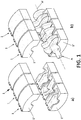
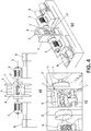
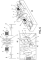
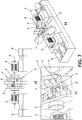
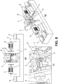
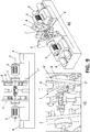
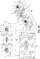
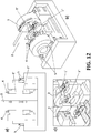
- the equipment for twisting crankshafts (A) proposed by the invention comprises at least three twisting modules (1); in the case depicted in Figures 1 to 11 there are three, whereas in Figure 12 there are five.
- Each twisting module (1) in turn comprises an upper tool (1') and a lower tool (1"), where said tools (1', 1") have an inner face by means of which they are facing one another, each tool (1', 1") having a cavity on said inner face the geometry of which corresponds with a portion of the outer shape of a crankpin of the crankshaft (A) to be twisted, such that the cavity defined by the facing tools (1', 1") of one and the same twisting module (1) corresponds with the complete outer shape of the crankpin.
- crankshaft (A) has a longitudinal axis (A') and can be arranged such that a crankpin is housed in the cavity defined by the facing tools (1', 1") of said at least one twisting module (1).
- each twisting module (1) are arranged on a supporting element (2) that can rotate independently with respect to an axis of rotation (3) coinciding with the longitudinal axis (A') of the crankshaft (A) when said crankshaft (A) is arranged in the equipment.
- the supporting element (2) corresponding to the central twisting module (1) does not rotate nor is it displaced in any case in the direction of the axis of rotation (3), although the invention likewise contemplates an embodiment in which it can rotate and be displaced.
- the supporting element (2) corresponding to the central module (1) is not depicted.
- crankpin that does not have to rotate.
- the tools (1', 1") of one and the same twisting module (1) can only effect a linear displacement with respect to the supporting element (2) in which they are arranged, said linear displacement being perpendicular to the axis of rotation (3).
- the supporting elements (2) can be longitudinally displaced in the direction of the axis of rotation (3) in order to move closer to one another in the direction towards the central twisting module (1).
- the equipment obviously has a bed serving as a base and support for the entire structure and elements of the equipment and incorporates the corresponding guides for longitudinal displacement of the supporting elements (2).
- first driving means (4) mounted on the actual supporting element (2).
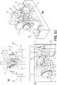
- each supporting element (2) with respect to the axis of rotation (3) is performed by second driving means (5).
- each supporting element (2) in the direction of the axis of rotation (3) is performed by third driving means (6).
- the first driving means (4) and third driving means (6) are hydraulic driving means but they could be pneumatic or of another type.
- the second driving means (5) are electric driving means, whereas in the embodiment of Figure 11 they are hydraulic driving means.
- the equipment comprises three twisting modules (1), the central one of which cannot be displaced or rotate with respect to the axis of rotation (3).
- the equipment comprises five twisting modules (1), the central one of which, likewise, cannot be displaced or rotate with respect to the axis of rotation (3).
- stiffening centering elements such as pins as well as square/tension member-type elements
Landscapes
- Engineering & Computer Science (AREA)
- Mechanical Engineering (AREA)
- Shafts, Cranks, Connecting Bars, And Related Bearings (AREA)
- Forging (AREA)
Applications Claiming Priority (1)
| Application Number | Priority Date | Filing Date | Title |
|---|---|---|---|
| PCT/ES2017/070632 WO2019058005A1 (fr) | 2017-09-25 | 2017-09-25 | Équipement et procédé pour tordre des vilebrequins |
Publications (2)
| Publication Number | Publication Date |
|---|---|
| EP3689487A1 true EP3689487A1 (fr) | 2020-08-05 |
| EP3689487B1 EP3689487B1 (fr) | 2021-08-25 |
Family
ID=60409302
Family Applications (1)
| Application Number | Title | Priority Date | Filing Date |
|---|---|---|---|
| EP17801070.8A Active EP3689487B1 (fr) | 2017-09-25 | 2017-09-25 | Équipement et procédé pour tordre des vilebrequins |
Country Status (3)
| Country | Link |
|---|---|
| EP (1) | EP3689487B1 (fr) |
| ES (1) | ES2900551T3 (fr) |
| WO (1) | WO2019058005A1 (fr) |
Families Citing this family (1)
| Publication number | Priority date | Publication date | Assignee | Title |
|---|---|---|---|---|
| CN115647229B (zh) * | 2022-11-15 | 2025-09-02 | 遵义金业机械铸造有限公司 | 一种双法兰盘薄壁异形件整形固定结构 |
Family Cites Families (4)
| Publication number | Priority date | Publication date | Assignee | Title |
|---|---|---|---|---|
| JPS57160537A (en) * | 1981-03-30 | 1982-10-02 | Sumitomo Metal Ind Ltd | Torsional press for crank shaft |
| JPS6021142A (ja) * | 1983-07-15 | 1985-02-02 | Honda Motor Co Ltd | クランクシヤフトの捩り成形装置 |
| US6220072B1 (en) * | 1998-12-16 | 2001-04-24 | Sumitomo Heavy Industries, Ltd. | Forming press of crankshafts |
| JP3737667B2 (ja) * | 2000-03-22 | 2006-01-18 | 住友重機械工業株式会社 | クランク軸の成形方法及びクランク軸用成形プレス |
-
2017
- 2017-09-25 ES ES17801070T patent/ES2900551T3/es active Active
- 2017-09-25 EP EP17801070.8A patent/EP3689487B1/fr active Active
- 2017-09-25 WO PCT/ES2017/070632 patent/WO2019058005A1/fr not_active Ceased
Also Published As
| Publication number | Publication date |
|---|---|
| EP3689487B1 (fr) | 2021-08-25 |
| ES2900551T3 (es) | 2022-03-17 |
| WO2019058005A1 (fr) | 2019-03-28 |
Similar Documents
| Publication | Publication Date | Title |
|---|---|---|
| CN105798657B (zh) | 一种工件夹紧装置 | |
| JP6419771B2 (ja) | プレス機 | |
| JP3186426U (ja) | プレス機械 | |
| TW201536447A (zh) | R-θ載台裝置及母螺紋加工裝置及可變曲柄裝置 | |
| EP3689487B1 (fr) | Équipement et procédé pour tordre des vilebrequins | |
| US6769600B1 (en) | Motor lamination notching apparatus and method with selectively positionable punches | |
| CN114433773A (zh) | 阀门配件锻造设备 | |
| CN110744186B (zh) | 具有柔性对中装置的联接型传动曲轴用装配设备 | |
| EP3689486B1 (fr) | Équipement et procédé pour tordre des vilebrequins | |
| US5105684A (en) | Crank driving device for press | |
| JP6916159B2 (ja) | 加工機及び加工方法 | |
| JP6866045B2 (ja) | 加工機及び加工方法 | |
| KR20040029295A (ko) | 환형 기계 | |
| JPS6219246B2 (fr) | ||
| JP4213096B2 (ja) | ピストン挿入方法およびピストン挿入装置 | |
| JP2004154921A (ja) | 工作機械 | |
| JP5978057B2 (ja) | プレス装置 | |
| KR101157015B1 (ko) | 기어 단조 기계의 치형다이 터닝 복원 장치 | |
| JP3515060B2 (ja) | 冷間鍛造方法及びその装置 | |
| CN108032111A (zh) | 加工差速器壳的定位机构 | |
| JP4812570B2 (ja) | 中空異形段付軸の成形方法及びその成形装置 | |
| KR100629211B1 (ko) | 다단식 단조성형기의 이송유닛 회전장치 | |
| JPH11309598A (ja) | モジュール式プレス | |
| KR20090113994A (ko) | 회전형 멀티 피어싱 장치 | |
| JP2006247728A (ja) | クランクシャフトにおけるカウンタウエイトの形状矯正方法とそれに用いるツイスト加工装置 |
Legal Events
| Date | Code | Title | Description |
|---|---|---|---|
| STAA | Information on the status of an ep patent application or granted ep patent |
Free format text: STATUS: UNKNOWN |
|
| STAA | Information on the status of an ep patent application or granted ep patent |
Free format text: STATUS: THE INTERNATIONAL PUBLICATION HAS BEEN MADE |
|
| PUAI | Public reference made under article 153(3) epc to a published international application that has entered the european phase |
Free format text: ORIGINAL CODE: 0009012 |
|
| STAA | Information on the status of an ep patent application or granted ep patent |
Free format text: STATUS: REQUEST FOR EXAMINATION WAS MADE |
|
| 17P | Request for examination filed |
Effective date: 20200317 |
|
| AK | Designated contracting states |
Kind code of ref document: A1 Designated state(s): AL AT BE BG CH CY CZ DE DK EE ES FI FR GB GR HR HU IE IS IT LI LT LU LV MC MK MT NL NO PL PT RO RS SE SI SK SM TR |
|
| AX | Request for extension of the european patent |
Extension state: BA ME |
|
| DAV | Request for validation of the european patent (deleted) | ||
| DAX | Request for extension of the european patent (deleted) | ||
| GRAP | Despatch of communication of intention to grant a patent |
Free format text: ORIGINAL CODE: EPIDOSNIGR1 |
|
| STAA | Information on the status of an ep patent application or granted ep patent |
Free format text: STATUS: GRANT OF PATENT IS INTENDED |
|
| INTG | Intention to grant announced |
Effective date: 20210414 |
|
| GRAS | Grant fee paid |
Free format text: ORIGINAL CODE: EPIDOSNIGR3 |
|
| GRAA | (expected) grant |
Free format text: ORIGINAL CODE: 0009210 |
|
| STAA | Information on the status of an ep patent application or granted ep patent |
Free format text: STATUS: THE PATENT HAS BEEN GRANTED |
|
| AK | Designated contracting states |
Kind code of ref document: B1 Designated state(s): AL AT BE BG CH CY CZ DE DK EE ES FI FR GB GR HR HU IE IS IT LI LT LU LV MC MK MT NL NO PL PT RO RS SE SI SK SM TR |
|
| REG | Reference to a national code |
Ref country code: CH Ref legal event code: EP |
|
| REG | Reference to a national code |
Ref country code: IE Ref legal event code: FG4D Ref country code: AT Ref legal event code: REF Ref document number: 1423261 Country of ref document: AT Kind code of ref document: T Effective date: 20210915 |
|
| REG | Reference to a national code |
Ref country code: DE Ref legal event code: R096 Ref document number: 602017044822 Country of ref document: DE |
|
| REG | Reference to a national code |
Ref country code: LT Ref legal event code: MG9D |
|
| REG | Reference to a national code |
Ref country code: NL Ref legal event code: MP Effective date: 20210825 |
|
| REG | Reference to a national code |
Ref country code: AT Ref legal event code: MK05 Ref document number: 1423261 Country of ref document: AT Kind code of ref document: T Effective date: 20210825 |
|
| PG25 | Lapsed in a contracting state [announced via postgrant information from national office to epo] |
Ref country code: HR Free format text: LAPSE BECAUSE OF FAILURE TO SUBMIT A TRANSLATION OF THE DESCRIPTION OR TO PAY THE FEE WITHIN THE PRESCRIBED TIME-LIMIT Effective date: 20210825 Ref country code: FI Free format text: LAPSE BECAUSE OF FAILURE TO SUBMIT A TRANSLATION OF THE DESCRIPTION OR TO PAY THE FEE WITHIN THE PRESCRIBED TIME-LIMIT Effective date: 20210825 Ref country code: RS Free format text: LAPSE BECAUSE OF FAILURE TO SUBMIT A TRANSLATION OF THE DESCRIPTION OR TO PAY THE FEE WITHIN THE PRESCRIBED TIME-LIMIT Effective date: 20210825 Ref country code: SE Free format text: LAPSE BECAUSE OF FAILURE TO SUBMIT A TRANSLATION OF THE DESCRIPTION OR TO PAY THE FEE WITHIN THE PRESCRIBED TIME-LIMIT Effective date: 20210825 Ref country code: LT Free format text: LAPSE BECAUSE OF FAILURE TO SUBMIT A TRANSLATION OF THE DESCRIPTION OR TO PAY THE FEE WITHIN THE PRESCRIBED TIME-LIMIT Effective date: 20210825 Ref country code: AT Free format text: LAPSE BECAUSE OF FAILURE TO SUBMIT A TRANSLATION OF THE DESCRIPTION OR TO PAY THE FEE WITHIN THE PRESCRIBED TIME-LIMIT Effective date: 20210825 Ref country code: BG Free format text: LAPSE BECAUSE OF FAILURE TO SUBMIT A TRANSLATION OF THE DESCRIPTION OR TO PAY THE FEE WITHIN THE PRESCRIBED TIME-LIMIT Effective date: 20211125 Ref country code: NO Free format text: LAPSE BECAUSE OF FAILURE TO SUBMIT A TRANSLATION OF THE DESCRIPTION OR TO PAY THE FEE WITHIN THE PRESCRIBED TIME-LIMIT Effective date: 20211125 Ref country code: PT Free format text: LAPSE BECAUSE OF FAILURE TO SUBMIT A TRANSLATION OF THE DESCRIPTION OR TO PAY THE FEE WITHIN THE PRESCRIBED TIME-LIMIT Effective date: 20211227 |
|
| PG25 | Lapsed in a contracting state [announced via postgrant information from national office to epo] |
Ref country code: PL Free format text: LAPSE BECAUSE OF FAILURE TO SUBMIT A TRANSLATION OF THE DESCRIPTION OR TO PAY THE FEE WITHIN THE PRESCRIBED TIME-LIMIT Effective date: 20210825 Ref country code: LV Free format text: LAPSE BECAUSE OF FAILURE TO SUBMIT A TRANSLATION OF THE DESCRIPTION OR TO PAY THE FEE WITHIN THE PRESCRIBED TIME-LIMIT Effective date: 20210825 Ref country code: GR Free format text: LAPSE BECAUSE OF FAILURE TO SUBMIT A TRANSLATION OF THE DESCRIPTION OR TO PAY THE FEE WITHIN THE PRESCRIBED TIME-LIMIT Effective date: 20211126 |
|
| REG | Reference to a national code |
Ref country code: ES Ref legal event code: FG2A Ref document number: 2900551 Country of ref document: ES Kind code of ref document: T3 Effective date: 20220317 |
|
| PG25 | Lapsed in a contracting state [announced via postgrant information from national office to epo] |
Ref country code: NL Free format text: LAPSE BECAUSE OF FAILURE TO SUBMIT A TRANSLATION OF THE DESCRIPTION OR TO PAY THE FEE WITHIN THE PRESCRIBED TIME-LIMIT Effective date: 20210825 |
|
| PG25 | Lapsed in a contracting state [announced via postgrant information from national office to epo] |
Ref country code: DK Free format text: LAPSE BECAUSE OF FAILURE TO SUBMIT A TRANSLATION OF THE DESCRIPTION OR TO PAY THE FEE WITHIN THE PRESCRIBED TIME-LIMIT Effective date: 20210825 |
|
| REG | Reference to a national code |
Ref country code: CH Ref legal event code: PL |
|
| REG | Reference to a national code |
Ref country code: BE Ref legal event code: MM Effective date: 20210930 |
|
| REG | Reference to a national code |
Ref country code: DE Ref legal event code: R097 Ref document number: 602017044822 Country of ref document: DE |
|
| PG25 | Lapsed in a contracting state [announced via postgrant information from national office to epo] |
Ref country code: SM Free format text: LAPSE BECAUSE OF FAILURE TO SUBMIT A TRANSLATION OF THE DESCRIPTION OR TO PAY THE FEE WITHIN THE PRESCRIBED TIME-LIMIT Effective date: 20210825 Ref country code: SK Free format text: LAPSE BECAUSE OF FAILURE TO SUBMIT A TRANSLATION OF THE DESCRIPTION OR TO PAY THE FEE WITHIN THE PRESCRIBED TIME-LIMIT Effective date: 20210825 Ref country code: RO Free format text: LAPSE BECAUSE OF FAILURE TO SUBMIT A TRANSLATION OF THE DESCRIPTION OR TO PAY THE FEE WITHIN THE PRESCRIBED TIME-LIMIT Effective date: 20210825 Ref country code: MC Free format text: LAPSE BECAUSE OF FAILURE TO SUBMIT A TRANSLATION OF THE DESCRIPTION OR TO PAY THE FEE WITHIN THE PRESCRIBED TIME-LIMIT Effective date: 20210825 Ref country code: EE Free format text: LAPSE BECAUSE OF FAILURE TO SUBMIT A TRANSLATION OF THE DESCRIPTION OR TO PAY THE FEE WITHIN THE PRESCRIBED TIME-LIMIT Effective date: 20210825 Ref country code: CZ Free format text: LAPSE BECAUSE OF FAILURE TO SUBMIT A TRANSLATION OF THE DESCRIPTION OR TO PAY THE FEE WITHIN THE PRESCRIBED TIME-LIMIT Effective date: 20210825 Ref country code: AL Free format text: LAPSE BECAUSE OF FAILURE TO SUBMIT A TRANSLATION OF THE DESCRIPTION OR TO PAY THE FEE WITHIN THE PRESCRIBED TIME-LIMIT Effective date: 20210825 |
|
| PLBE | No opposition filed within time limit |
Free format text: ORIGINAL CODE: 0009261 |
|
| STAA | Information on the status of an ep patent application or granted ep patent |
Free format text: STATUS: NO OPPOSITION FILED WITHIN TIME LIMIT |
|
| PG25 | Lapsed in a contracting state [announced via postgrant information from national office to epo] |
Ref country code: LU Free format text: LAPSE BECAUSE OF NON-PAYMENT OF DUE FEES Effective date: 20210925 Ref country code: IE Free format text: LAPSE BECAUSE OF NON-PAYMENT OF DUE FEES Effective date: 20210925 Ref country code: BE Free format text: LAPSE BECAUSE OF NON-PAYMENT OF DUE FEES Effective date: 20210930 |
|
| 26N | No opposition filed |
Effective date: 20220527 |
|
| PG25 | Lapsed in a contracting state [announced via postgrant information from national office to epo] |
Ref country code: SI Free format text: LAPSE BECAUSE OF FAILURE TO SUBMIT A TRANSLATION OF THE DESCRIPTION OR TO PAY THE FEE WITHIN THE PRESCRIBED TIME-LIMIT Effective date: 20210825 Ref country code: LI Free format text: LAPSE BECAUSE OF NON-PAYMENT OF DUE FEES Effective date: 20210930 Ref country code: CH Free format text: LAPSE BECAUSE OF NON-PAYMENT OF DUE FEES Effective date: 20210930 |
|
| PG25 | Lapsed in a contracting state [announced via postgrant information from national office to epo] |
Ref country code: CY Free format text: LAPSE BECAUSE OF FAILURE TO SUBMIT A TRANSLATION OF THE DESCRIPTION OR TO PAY THE FEE WITHIN THE PRESCRIBED TIME-LIMIT Effective date: 20210825 |
|
| PG25 | Lapsed in a contracting state [announced via postgrant information from national office to epo] |
Ref country code: HU Free format text: LAPSE BECAUSE OF FAILURE TO SUBMIT A TRANSLATION OF THE DESCRIPTION OR TO PAY THE FEE WITHIN THE PRESCRIBED TIME-LIMIT; INVALID AB INITIO Effective date: 20170925 |
|
| PG25 | Lapsed in a contracting state [announced via postgrant information from national office to epo] |
Ref country code: MK Free format text: LAPSE BECAUSE OF FAILURE TO SUBMIT A TRANSLATION OF THE DESCRIPTION OR TO PAY THE FEE WITHIN THE PRESCRIBED TIME-LIMIT Effective date: 20210825 |
|
| PG25 | Lapsed in a contracting state [announced via postgrant information from national office to epo] |
Ref country code: MT Free format text: LAPSE BECAUSE OF FAILURE TO SUBMIT A TRANSLATION OF THE DESCRIPTION OR TO PAY THE FEE WITHIN THE PRESCRIBED TIME-LIMIT Effective date: 20210825 |
|
| PGFP | Annual fee paid to national office [announced via postgrant information from national office to epo] |
Ref country code: DE Payment date: 20250919 Year of fee payment: 9 |
|
| PGFP | Annual fee paid to national office [announced via postgrant information from national office to epo] |
Ref country code: IT Payment date: 20250923 Year of fee payment: 9 |
|
| PGFP | Annual fee paid to national office [announced via postgrant information from national office to epo] |
Ref country code: GB Payment date: 20250820 Year of fee payment: 9 |
|
| PGFP | Annual fee paid to national office [announced via postgrant information from national office to epo] |
Ref country code: FR Payment date: 20250820 Year of fee payment: 9 |
|
| PG25 | Lapsed in a contracting state [announced via postgrant information from national office to epo] |
Ref country code: TR Free format text: LAPSE BECAUSE OF FAILURE TO SUBMIT A TRANSLATION OF THE DESCRIPTION OR TO PAY THE FEE WITHIN THE PRESCRIBED TIME-LIMIT Effective date: 20210825 |
|
| PGFP | Annual fee paid to national office [announced via postgrant information from national office to epo] |
Ref country code: ES Payment date: 20251003 Year of fee payment: 9 |