EP3696385B1 - Dispositif de refroidissement pour une machine de travail agricole - Google Patents
Dispositif de refroidissement pour une machine de travail agricole Download PDFInfo
- Publication number
- EP3696385B1 EP3696385B1 EP19209665.9A EP19209665A EP3696385B1 EP 3696385 B1 EP3696385 B1 EP 3696385B1 EP 19209665 A EP19209665 A EP 19209665A EP 3696385 B1 EP3696385 B1 EP 3696385B1
- Authority
- EP
- European Patent Office
- Prior art keywords
- counter
- scraper
- comb
- cooling device
- screen
- Prior art date
- Legal status (The legal status is an assumption and is not a legal conclusion. Google has not performed a legal analysis and makes no representation as to the accuracy of the status listed.)
- Active
Links
Images


Classifications
-
- F—MECHANICAL ENGINEERING; LIGHTING; HEATING; WEAPONS; BLASTING
- F01—MACHINES OR ENGINES IN GENERAL; ENGINE PLANTS IN GENERAL; STEAM ENGINES
- F01P—COOLING OF MACHINES OR ENGINES IN GENERAL; COOLING OF INTERNAL-COMBUSTION ENGINES
- F01P11/00—Component parts, details, or accessories not provided for in, or of interest apart from, groups F01P1/00 - F01P9/00
- F01P11/12—Filtering, cooling, or silencing cooling-air
-
- B—PERFORMING OPERATIONS; TRANSPORTING
- B01—PHYSICAL OR CHEMICAL PROCESSES OR APPARATUS IN GENERAL
- B01D—SEPARATION
- B01D46/00—Filters or filtering processes specially modified for separating dispersed particles from gases or vapours
- B01D46/0052—Filters or filtering processes specially modified for separating dispersed particles from gases or vapours with filtering elements moving during filtering operation
- B01D46/0056—Filters or filtering processes specially modified for separating dispersed particles from gases or vapours with filtering elements moving during filtering operation with rotational movement
-
- B—PERFORMING OPERATIONS; TRANSPORTING
- B01—PHYSICAL OR CHEMICAL PROCESSES OR APPARATUS IN GENERAL
- B01D—SEPARATION
- B01D46/00—Filters or filtering processes specially modified for separating dispersed particles from gases or vapours
- B01D46/24—Particle separators, e.g. dust precipitators, using rigid hollow filter bodies
- B01D46/2403—Particle separators, e.g. dust precipitators, using rigid hollow filter bodies characterised by the physical shape or structure of the filtering element
-
- B—PERFORMING OPERATIONS; TRANSPORTING
- B01—PHYSICAL OR CHEMICAL PROCESSES OR APPARATUS IN GENERAL
- B01D—SEPARATION
- B01D46/00—Filters or filtering processes specially modified for separating dispersed particles from gases or vapours
- B01D46/66—Regeneration of the filtering material or filter elements inside the filter
- B01D46/68—Regeneration of the filtering material or filter elements inside the filter by means acting on the cake side involving movement with regard to the filter elements
- B01D46/681—Regeneration of the filtering material or filter elements inside the filter by means acting on the cake side involving movement with regard to the filter elements by scrapers, brushes or the like
Definitions
- the present application relates to a cooling device for an agricultural harvesting machine according to the preamble of claim 1.
- the cooling device includes a rotatable cooler basket, which is equipped with at least one scraper and at least one counter comb.
- a cooling air volume flow is supplied to cool the internal combustion engine in particular, by means of which the internal combustion engine and possibly other machine parts can be cooled. Since during a harvesting process the ambient air can be contaminated with a high number of dirt particles, in particular dust and the like, it is necessary to filter the cooling air volume flow before it is fed to the internal combustion engine.
- the cooler basket represents, so to speak, a first filter stage through which the cooling air volume flow must pass before it reaches the internal combustion engine.
- the cooler basket is rotatably mounted about a rotation axis and can be driven in rotation so that it can rotate about the rotation axis.
- This functionality is advantageous in order to systematically clean a sieve surface of the cooler basket, by means of which the cooling air volume flow can be sieved, in a particularly simple manner. This is based on the idea that the dirt particles described gradually clog the screen surface of the cooler basket and thereby increase flow resistance for the cooling air volume flow. It is therefore typically necessary to continually clean the screen surface so that an effective flow cross section, which is available to the cooling air volume flow in total to flow through the screen surface, can be kept at a certain minimum level.
- the rotatability of the cooler basket makes it possible to combine it with a stationary suction device, on which the sieve surface is continuously guided along as the cooler basket rotates, so that adhering dirt particles can be extracted. Furthermore, the rotation of the cooler basket causes a centrifugal force on the dirt particles adhering to the sieve surface, whereby a certain cleaning performance is achieved independently of a suction device, in that the dirt particles are "thrown away" radially outwards in relation to the axis of rotation as a result of the acting centrifugal force.
- the radiator basket is cup-shaped, having a (typically flat) end face and a circumferential circumferential surface which extends at an angle (typically 90°) to the end face.
- the front surface and the peripheral surface of the cooler basket are at least partially, preferably completely, formed by the screen surface.
- the scraper interacts with the radiator basket and is arranged on the end face and the peripheral surface of the radiator basket. It is so firmly connected to the radiator basket that it rotates with the radiator basket as it rotates.
- the counter comb is intended to interact with the scraper. It is arranged in a stationary manner - viewed relative to the radiator basket - so that the radiator basket together with the scraper is moved relative to the counter comb as the radiator basket rotates.
- the counter-comb is arranged in such a way that the wiper or at least part of it passes the counter-comb cyclically in the course of the rotation of the radiator basket, with the counter-comb engaging with the wiper in each case.
- the scraper comprises a plurality of spaced-apart elevations which are designed to complement a plurality of fingers which are arranged on the counter comb.
- the fingers of the counter comb and the elevations of the wiper are suitable for meshing with one another, so that the fingers of the counter comb pass through spaces between adjacent elevations of the wiper that rotates with the radiator basket.
- a cooling device of the type described above is already known in the prior art.
- EP 0 566 981 B1 This describes a cooling device in which a circular, flat sieve surface is rotated about a central axis of rotation.
- Two scrapers are arranged on the screen surface and extend radially with respect to the axis of rotation, each of which has a plurality of equidistant elevations.
- the scrapers each work together with a counter comb, which is arranged in a stationary manner in relation to the rotatable screen surface. This results in the scrapers engaging with the counter-comb once per revolution of the screen surface, with fingers of the counter-comb penetrating spaces that extend between the adjacent elevations of the scrapers.
- the known cooling device is disadvantageous in that a mechanical load on the screen surface in the course of the engagement of the counter comb and scraper is comparatively large.
- a jam of material can occur at the elevations of the scraper, which puts a high peak load on the scraper in the course of engagement with the counter comb can cause.
- damage to the screen surface can occur, which then loses its function, so that the desired screening effect regarding the cooling air volume flow loaded with dirt particles is at least partially lost.
- the present application is therefore based on the object of providing a cooling device that is improved compared to the prior art.
- the cooling device is characterized in that at least one elevation of the scraper is formed by a truncated cone.
- This truncated cone is advantageously designed in such a way that it tapers in a direction away from the sieve surface, starting from a base of the scraper which faces the sieve surface of the cooler basket. In this way, an outer lateral surface of the truncated cone forms, so to speak, a "ramp" leading away from the sieve surface, by means of which material collected by the scraper can be guided away from the sieve surface.
- the cooling device has many advantages.
- the design of at least one elevation, preferably a plurality of elevations, more preferably all elevations, in the form of a truncated cone has the result that plant residues, which are captured by the scraper in the course of the rotation of the radiator basket, are removed when engaged with the counter comb over the relative to the base of the scraper can be diverted from the sloping lateral surface of the cone truncated in the direction away from the screen surface.
- This requires a comparatively low force, which prevents mechanical overloading of the screen surface and the resulting damage to it.
- the accumulation behavior observed in the prior art at the elevations of the scraper there is avoided.
- At least one truncated cone has a recess, as a result of which the truncated cone is at least partially hollow.
- This configuration has the particular advantage that the outer lateral surface of the truncated cone borders an inner lateral surface, which is caused by the recess. This applies at least in the case that the recess extends from an end of the cone truncated away from the screen surface in the direction of the screen surface.
- the truncated cone At the transition between the outer lateral surface and the inner lateral surface, the truncated cone then has a circumferential Cutting edge, by means of which plant residues can be shredded particularly well during the engagement of the scraper with the counter comb.
- the recess in the truncated cone serves to form the cutting edge at the transition from the outer lateral surface to the inner lateral surface of the recess.
- a central axis of the recess which preferably has a round cross section, extends perpendicular to the screen surface.
- the recess completely penetrates the scraper in the area of the truncated cone, so that the truncated cone is designed to be completely hollow.
- the recess can be designed, for example, in the form of a blind hole
- the fully hollow design in which the truncated cone is completely penetrated from its end facing away from the screen surface to the end of the scraper facing the screen surface, allows an air flow through the cone stump.
- the cone stump becomes clogged during operation of the harvesting machine, with a suction effect being exerted on the recess, particularly in combination with a suction device, and in this way any material that has accumulated in the recess can be sucked out.
- the recess also offers an alternative volume for plant residues that are displaced in the course of an intervention with the counter comb. The possibility for the material to penetrate into the recess of a respective truncated cone leads to a further reduced accumulation effect on the wiper.
- an inner lateral surface of the truncated cone which it has in the area of the recess, and an outer lateral surface of the truncated cone together form an angle of at least 35°, preferably at least 40°, more preferably at least 45°.
- the flatter design of the angle between the inner lateral surface and the outer lateral surface is generally accompanied by a flatter rise of the truncated cone starting from its base.
- the flatter rise of each cone stub leads to a better diverting effect of the cone stub and therefore to a reduced accumulation effect in the course of the engagement with the counter comb.
- the angle between the inner lateral surface and the outer lateral surface of the Cone stump does not exceed a value of 60°, preferably 55°, more preferably 50°.
- the truncated cone is formed by a truncated cone.
- This is particularly easy to produce in terms of production technology.
- the design of the truncated cone by means of a punching is fundamentally advantageous regardless of its shape as a truncated cone.
- the punching offers the advantage that the material directed outwards, i.e. the material directed away from the screen surface, can be brought into a cone or truncated cone shape particularly easily, whereby the diversion effect described above as being advantageous for the material captured by the scraper can be generated.
- the latter is due to the outer lateral surface, which is characteristic of a truncated cone as well as a truncated cone and is inclined relative to the base of the wiper.
- a longitudinal axis of the counter-comb and a longitudinal axis of an effective section of the wiper which is directly connected to the counter-comb During the rotation of the radiator basket, they are designed to be inclined towards each other. This inclination is preferably reflected in the fact that projections of the longitudinal axes of the counter comb and scraper into the screen surface interacting with the scraper together enclose an angle of at least 10°, preferably at least 15°, more preferably at least 20°.
- the inclined design of the counter-comb and wiper relative to one another has the technical effect that the wiper or the affected effective section thereof, which interacts with the counter-comb, gradually engages with the counter-comb over its length as the counter-comb passes.
- the fingers of the counter comb do not simultaneously pass through the respectively assigned gaps between adjacent elevations of the scraper, but rather pass through the gaps one after the other in time, so to speak.
- a gap between the two most radially inner elevations of the wiper which is the furthest radially inward relative to the axis of rotation of the radiator basket, is first penetrated by a finger of the counter comb that is furthest radially inward.
- the counter comb and the scraper Alternatively or in addition to an arrangement of the counter comb and the scraper relative to one another, it is also conceivable to design the counter comb and/or the scraper curved in order to equalize a period of engagement of the individual fingers of the counter comb with the respective associated gaps of the scraper and in particular a sudden, simultaneous intervention several or even all of the fingers of the counter comb with the gaps between the wiper.
- both the counter comb and the wiper are designed to be straight. This is particularly advantageous from a manufacturing perspective.
- the effective section of the wiper that corresponds to the end face of the radiator basket is straight, it is particularly advantageous if a longitudinal axis of the same runs at an eccentricity with respect to the axis of rotation of the radiator basket. In other words, in such a design the wiper runs off-center with respect to the axis of rotation.
- This configuration is particularly well suited to effecting the desired equalization of the times of engagement of the individual fingers of the counter comb with the associated spaces of the wiper.
- a corresponding example is illustrated below in connection with the exemplary embodiment.
- the counter-comb has at least two elongated holes, by means of which a distance of the counter-comb from the respectively assigned sieve surface can be adjusted. In this way, in particular, a distance between the counter comb and the scraper can be adjusted, whereby the joint effect of the counter comb and scraper can be adjusted.
- such a design of the cooling device is of particular advantage, which includes at least one suction device, by means of which adhering to the sieve surface Particles can be extracted.
- the functionality of such a suction device has already been explained above.
- a particularly advantageous embodiment is in which the suction device has at least one housing which extends in the radial direction with respect to the end face of the radiator basket and thereby completely covers the radius of the radiator basket. In this way, it is particularly easy to apply a negative pressure generated by the suction device over the entire end face as the radiator basket rotates about the axis of rotation.
- the housing also interacts with the peripheral surface of the cooler basket, so that particles adhering to the sieve surface there can also be sucked out using the suction device.
- the counter comb is advantageously arranged directly on the housing of the suction device, wherein it is preferably arranged on a front side of the housing. Said front side describes the side of the housing of the suction device that the scraper passes first during the rotation of the radiator basket.
- This configuration has the advantage that a shredding effect of the engagement of the counter comb and scraper on the plant residues takes place when the scraper just comes into engagement with the housing of the suction device. In this way, shredded plant residues that the scraper then “drags along” can be sucked off directly using the suction device on the scraper.
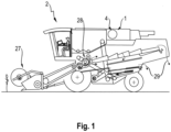
- FIG. 1 An embodiment that is in the Figures 1 to 7 is illustrated relates to a cooling device 1 according to the invention, which is suitable for an agricultural harvester 2 .
- a harvester 2 is shown in a cross section Figure 1 shown, whereby the harvester 2 is formed here by a combine harvester.
- This has a cutting unit 27 and a threshing drum 28 at a front end.
- plants can be cut, which can then be fed from the cutting unit 27 by means of an inclined conveyor 38 in the direction of the threshing drum 28 .
- the threshing drum 28 fruits of the plants are separated from plant residues, whereupon at least some of the fruits and plant residues are fed together to a separating device 39 connected downstream of the threshing drum 28 .
- the working elements of the harvester 2 are driven by an internal combustion engine, not shown in the figures.
- This internal combustion engine requires cooling, which is accomplished by means of the cooling device 1 .
- the cooling device 1 has a cooler basket 4 arranged on a pivoting door 30 of the internal combustion engine, which is rotatably mounted about an axis of rotation 3 .
- the swing door 30 offers an inspection option for the internal combustion engine.
- the radiator basket 4 is cup-shaped, so that it has a circular plate-shaped end face 7 and a circumferential circumferential surface 8 which extends at an angle relative to the end face 7 .
- the end face 7 is flat, with the peripheral surface 8 adjoining the end face 7 at a right angle.
- the end face 7 of the radiator basket 4 is visible.
- the end face 7 and the peripheral surface 8 are each designed as a sieve surface 16 , by means of which a cooling air volume flow that flows from an environment 41 through the cooler basket 4 in the direction of the internal combustion engine can be sieved.
- the design of the end face 7 and the peripheral surface 8 as a sieve surface 16 is necessary in order to retain dirt particles that are in the ambient air as a result of the harvesting process, so that the cooling air volume flow supplied to the internal combustion engine is as free as possible of these dirt particles.
- the dirt particles come in particular from the plant residues that are ejected at the back of the harvester 2 . In the case of a harvesting machine designed as a forage harvester, it is also typical that leaves, for example from corn plants, are sucked in by the cooling device 1 and settle on the sieve surface 16 .
- the cooling device 1 has a scraper 5 and two counter-combs 6 that interact with the scraper 5 .
- the wiper 5 is L-shaped, with a first effective section of the wiper 5 extending along the end face 7 of the radiator basket 4 and a second effective section of the wiper 5 extending along the peripheral surface 8 of the radiator basket 4 .
- the scraper 5 is firmly connected to the radiator basket 4 , so that it rotates around the axis of rotation 3 as the radiator basket 4 rotates. There is therefore no relative movement between the wiper 5 and the radiator basket 4 .
- the scraper 5 has the task of capturing dirt particles and feeding them together to the counter combs 6 .
- the cooling device 1 comprises two counter-combs 6 , the first counter-comb 6 cooperating with the effective section of the wiper 5 , which is assigned to the end face 7 of the radiator basket 4 , and the second counter-comb 6 interacting with the effective section of the wiper 5 , which is the Circumferential surface 8 of the radiator basket 4 is assigned.
- the counter combs 6 each have a plurality of fingers 10 which extend from a base of the respective counter comb 6 in the direction of the associated sieve surface 16 .
- the fingers 10 of the counter combs 6 are suitable for interacting with gaps 11 which extend between adjacent elevations 9 of the wipers 5 .
- Said elevations 9 each extend from a base of the scraper 5 in a direction facing away from the sieve surface 16 .
- the elevations 9 are each arranged next to one another on the wiper 5 .
- the counter-combs 6 and the wiper 5 are coordinated with one another in such a way that the fingers 10 of the counter-combs 6 pass through the spaces 11 between adjacent elevations 9 of the wipers 5 in the course of the movement of the wiper 5 past the counter-combs 6 .
- the counter combs 6 are arranged in a stationary manner with respect to the radiator basket 4 , so that they do not follow the rotation of the radiator basket 4 about the axis of rotation 3 .
- the rotation of the cooler basket 4 together with the wiper 5 results in the wiper 5 moving relative to the counter-combs 6 and passing the counter-combs 6 once per revolution of the cooler basket 4 about the axis of rotation 3 .
- the fingers 10 of the counter combs 6 pass through the spaces 11 between the adjacent elevations 9 of the wiper 5 once.
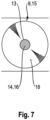
- the elevations 9 of the scraper 5 are - as can be seen in particular from the Figures 3 to 7 results - in the example shown, each formed by a truncated cone 15 .
- truncated cones 15 are each formed by truncated cones which extend from the base of the scraper 5 in the direction of the counter combs 6 .
- the cone stubs 15 are oriented in such a way that they taper starting from the base of the scraper 5 in the direction facing away from the sieve surface 16 .
- an outer lateral surface 18 of a respective truncated cone 15 can be used as a deflection surface, so to speak, by means of which any dirt particles can be repelled in a direction facing away from the sieve surface 16 .
- the elevations 9 in the example shown are completely hollow, the elevations 9 each having a recess 14 which completely penetrates the respective elevation 9 in a direction perpendicular to the sieve surface 16 .
- the surveys 9 therefore comprise an inner lateral surface 17 at their respective recess 14 , which extends at an angle relative to the outer lateral surface 18 of the respective survey 9 .
- the inner lateral surface 17 and the outer lateral surface 18 border one another and there together form a cutting edge 13 within a plane 37 parallel to the sieve surface 16 . Due to the design of the truncated cones 15 in the form of truncated cones, the cutting edges 13 are circular here.
- the elevations 9 are each formed by a punching that is produced by punching.
- the recess 14 which completely penetrates the respective elevation 9 and, on the other hand, the truncated cone shape can be produced particularly easily, and the cutting edge 13 can also be designed to have particularly sharp edges as a transition from the inner lateral surface 17 to the outer lateral surface 18 .
- the formation of such a sharp cutting edge 13 has the advantage that any particles can be cut in the course of the engagement of the scraper 5 with a respective counter comb 6 by means of the cutting edge 13 and comminuted in this way. This comminution is particularly advantageous with regard to suctioning off the particles using a suction device.
- the shape of a respective truncated cone 15 is designed in the example shown such that the outer lateral surface 18 forms an angle 19 of approximately 50 with an orthogonal 44 , which is arranged perpendicular to the base of the scraper 5 on a foot 45 of the respective truncated cone 15 ° includes.
- the cone stubs 15 are therefore comparatively flat, so that they have the desired diverting effect away from the sieve surface 16 achieve particularly well.
- the cone stubs 15 are each arranged at a distance 36 from one another, with one of the gaps 11 extending between adjacent cone stubs 15 .
- the fingers 10 of the counter-combs 6 are equally arranged at a distance 36 from one another, so that the fingers 10 pass through the gaps 11 in the middle in relation to the counter-combs 6 as the wiper 5 passes.
- the cooling device 1 further comprises a suction device 24 , which is arranged in a stationary manner in relation to the cooler basket 4 .
- the suction device 24 cooperates with a suction pipe 31 , which interacts with a housing 25 at an end assigned to the radiator basket 4 .
- the housing 25 is L-shaped, comparable to the wiper 5 , so that it extends both radially in relation to the axis of rotation 3 of the radiator basket 4 along the end face 7 and along the peripheral surface 8 of the radiator basket 4 .
- the suction device 24 has a fan, by means of which a negative pressure can be generated on the housing 25 , so that dirt particles adhering to the sieve surface 16 can be sucked away. This suction is easier the smaller the dirt particles are.
- any dirt particles can be comminuted as a result of the interaction of the scraper 5 with the counter combs 6 .
- the counter-combs 6 are arranged directly on the housing 25 of the suction device 24 , with the counter-combs 6 being assigned to a front side 26 of the housing 25 .
- This front side 26 is characterized in that the wiper 5 moves in the course of a rotation of the radiator basket 4 in the in Figure 2 illustrated direction of rotation 33 , which corresponds to the clockwise direction, initially engages with the counter-combing 6 as the wiper 5 moves past the housing 25 , before the wiper 5 enters the effective range of the suction device 24 .
- the latter extends below the housing 25 .
- the wiper 5 finally emerges, so to speak, from under the housing 25 on a back side 32 of the housing 25 .
- the counter-combs 6 are mounted on the housing 25 by means of elongated holes 23 .
- the elongated holes 23 enable the counter-combs 6 to be adjusted, so that a distance between the scraper 5 and the counter-combs 6 can be adjusted particularly easily.
- This setting then has a direct effect on the shredding effect of the counter-combs 6 , with the tighter guidance of the counter-combs 6 and scrapers 5 resulting in a smaller escape gap between the two components. Consequently, for a closer guidance for a more effective shredding of any dirt particles.
- the cooling device 1 shown is particularly advantageous in that the counter comb 6 assigned to the end face 7 and the assigned effective section of the wiper 5 are aligned with one another at an angle 22 .
- Figure 4 This embodiment is reflected in the fact that a longitudinal axis 21 of the effective section of the wiper 5 assigned to the end face 7 and a longitudinal axis 20 of the assigned counter comb 6 together enclose the angle 22 . Seen geometrically, this angle 22 results between projections of the longitudinal axis 20 of the counter comb 6 and the longitudinal axis 21 of the effective section of the scraper 5 into the sieve surface 16 or the end surface 7 of the radiator basket 4 . In the example shown, the angle 22 is approximately 25°.
- the embodiment shown has the advantage that the fingers 10 of the counter comb 6 do not pass through the spaces 11 between the adjacent elevations 9 simultaneously or "in one fell swoop" when passing the scraper 5 , but rather interact with the scraper 5 one after the other, so to speak. A resistance that arises as a result of the interaction therefore does not occur concentrated all at once, but is distributed over a period of effect, over which the wiper 5 is guided past the counter comb 6 .
- the scraper 5 in the example shown is designed such that its effective section facing the end face 7 is arranged eccentrically with respect to the axis of rotation 3 of the radiator basket 4 .
- Figure 4 There it can be seen that the longitudinal axis 21 of the effective section of the wiper 5 assigned to the end face 7 is at a distance 34 from a point of penetration 42 of the axis of rotation 3 through the end face 7 of the radiator basket 4 .
- This configuration has the result that the effective section of the wiper 5 assigned to the end face 7 does not extend purely radially in relation to the axis of rotation 3 .
- the scraper 5 is deflected at a transition from the end face 7 to the peripheral surface 8 of the radiator basket 4 by means of a bend 35 , so that the scraper 5 has the L shape described.
- Figure 5 The scraper 5 has a plurality of bores 43 which are arranged distributed over its length. These bores 43 serve to transmit force to the wiper 5 on the radiator basket 4 by means of appropriate fastening means mount, whereby the spatial equalization of the bores 43 contributes to the bearing forces of the wiper 5 being distributed as far as possible into the radiator basket 4 . This has the advantage that point mechanical loads on the radiator basket 4 are kept as low as possible.
Landscapes
- Chemical & Material Sciences (AREA)
- Engineering & Computer Science (AREA)
- Chemical Kinetics & Catalysis (AREA)
- Combustion & Propulsion (AREA)
- Mechanical Engineering (AREA)
- General Engineering & Computer Science (AREA)
- Physics & Mathematics (AREA)
- Geometry (AREA)
- Cooling, Air Intake And Gas Exhaust, And Fuel Tank Arrangements In Propulsion Units (AREA)
- Harvesting Machines For Specific Crops (AREA)
Claims (11)
- Équipement de refroidissement (1) pour une machine agricole de récolte (2), incluant- un tamis de radiateur (4) tournant autour d'un axe de rotation (3),- au moins un racleur (5) ainsi que- au moins un contre-peigne (6),le tamis de radiateur (4) étant conçu en forme de pot, de sorte qu'il comporte une face frontale (7) ainsi qu'une surface périphérique tournante (8) s'étendant selon un angle par rapport à la face frontale (7),le tamis de radiateur (4) étant formé, dans la zone de sa face frontale (7) ainsi que de sa surface périphérique (8), respectivement au moins en partie par une surface de tamis (16) à travers laquelle un flux volumique d'air de refroidissement peut pénétrer dans un espace intérieur du tamis de radiateur (4) à partir d'un environnement,le racleur (5) étant solidarisé au tamis de radiateur (4), de façon qu'il puisse tourner avec le tamis de radiateur (4),le racleur (5) comportant une pluralité de reliefs (9) distants les uns des autres,le contre-peigne (6) étant disposé en position fixe considéré relativement au tamis de radiateur (4), de sorte que le tamis de radiateur (4) est rotatif par rapport au contre-peigne (6),le contre-peigne (6) comportant une pluralité de doigts (10) au moyen desquels le contre-peigne (6) et le racleur (5) s'emboîtent l'un dans l'autre au cours de la rotation du tamis de radiateur (4), de sorte que les doigts (10) du contre-peigne (6) traversent des interstices (11) entre des reliefs voisins (9) du racleur (5) tournant avec le tamis de radiateur (4),caractérisé en ce quele racleur (5) est disposé sur la face frontale (7) et sur la surface périphérique (8) du tamis de radiateur (4),au moins un relief (9) du racleur (5) étant formé par un cône tronqué (15).
- Équipement de refroidissement (1) selon la revendication 1, caractérisé en ce que le cône tronqué (15) comporte un évidement (14) et est ainsi conçu de manière au moins partiellement creuse, le cône tronqué (15) comportant, à son extrémité (12) située à l'opposé de la surface de tamis (16), une arête de coupe tournante (13).
- Équipement de refroidissement (1) selon la revendication 2, caractérisé en ce que l'évidement (14) traverse entièrement le racleur (5) dans la zone du relief (9), de sorte que le cône tronqué (15) est conçu de manière entièrement creuse.
- Équipement de refroidissement (1) selon la revendication 2 ou 3, caractérisé en ce qu'une surface latérale intérieure (17) du cône tronqué (15) dans la zone de l'évidement (14) et une surface latérale extérieure (18) du cône tronqué (15) présentent conjointement un angle (19) d'au moins 35°, préférentiellement d'au moins 40°, plus préférentiellement d'au moins 45°.
- Équipement de refroidissement (1) selon une des revendications 1 à 4, caractérisé en ce que le cône tronqué (15) est formé par un poinçonnage qui traverse le racleur (5) en s'éloignant de la surface de tamis (16).
- Équipement de refroidissement (1) selon une des revendications 1 à 5, caractérisé en ce qu'un axe longitudinal (20) du contre-peigne (6) et un axe longitudinal (21) d'une portion active du racleur (5) coopérant avec le contre-peigne (6) sont inclinés l'un par rapport à l'autre, préférentiellement des projections des axes longitudinaux (20, 21) dans la surface de tamis (16) coopérant avec le racleur (5) incluant conjointement un angle (22) d'au moins 10°, préférentiellement d'au moins 15°, plus préférentiellement d'au moins 20°.
- Équipement de refroidissement (1) selon une des revendications 1 à 6, caractérisé en ce qu'au moins une portion active du racleur (5) correspondant avec la face frontale (7) du tamis de radiateur (4) est conçue de manière en soi rectiligne.
- Équipement de refroidissement (1) selon la revendication 7, caractérisé en ce qu'un axe longitudinal (21) de la portion active coopérant avec la face frontale (7) s'étend de manière excentrée par rapport à l'axe de rotation (3) du tamis de radiateur (4).
- Équipement de refroidissement (1) selon une des revendications 1 à 8, caractérisé en ce que le contre-peigne (6) comporte au moins deux trous oblongs (23) au moyen desquels un écartement du contre-peigne (6) par rapport à la surface de tamis respectivement associée (16) est réglable.
- Équipement de refroidissement (1) selon une des revendications 1 à 9, caractérisé par un équipement d'aspiration (24) au moyen duquel des particules adhérant à la surface de tamis (16) sont aspirables.
- Équipement de refroidissement (1) selon la revendication 10, caractérisé en ce que le contre-peigne (6) est associé à un carter (25) de l'équipement d'aspiration (24), préférentiellement le contre-peigne (6) - considéré dans la direction de rotation du tamis de radiateur (4) - étant disposé sur un côté avant (26) du carter (25).
Applications Claiming Priority (1)
| Application Number | Priority Date | Filing Date | Title |
|---|---|---|---|
| DE102019103410.8A DE102019103410A1 (de) | 2019-02-12 | 2019-02-12 | Kühleinrichtung für eine landwirtschaftliche Arbeitsmaschine |
Publications (3)
| Publication Number | Publication Date |
|---|---|
| EP3696385A2 EP3696385A2 (fr) | 2020-08-19 |
| EP3696385A3 EP3696385A3 (fr) | 2020-10-07 |
| EP3696385B1 true EP3696385B1 (fr) | 2024-01-10 |
Family
ID=68609939
Family Applications (1)
| Application Number | Title | Priority Date | Filing Date |
|---|---|---|---|
| EP19209665.9A Active EP3696385B1 (fr) | 2019-02-12 | 2019-11-18 | Dispositif de refroidissement pour une machine de travail agricole |
Country Status (2)
| Country | Link |
|---|---|
| EP (1) | EP3696385B1 (fr) |
| DE (1) | DE102019103410A1 (fr) |
Families Citing this family (2)
| Publication number | Priority date | Publication date | Assignee | Title |
|---|---|---|---|---|
| DE102021111281A1 (de) | 2021-04-30 | 2022-11-03 | Claas Selbstfahrende Erntemaschinen Gmbh | Siebeinrichtung mit zumindest einer Absaugdüse |
| CN113181720B (zh) * | 2021-06-28 | 2021-09-07 | 潍坊利金机械设备有限公司 | 一种可拆卸式拼接型空气过滤器 |
Family Cites Families (4)
| Publication number | Priority date | Publication date | Assignee | Title |
|---|---|---|---|---|
| US3837149A (en) * | 1973-06-27 | 1974-09-24 | Deere & Co | Engine enclosure and cooling system with rotary filter |
| US5183487A (en) | 1992-04-24 | 1993-02-02 | Deere & Company | Trash handling apparatus for a self-cleaning rotary screen |
| GB0812966D0 (en) * | 2008-07-16 | 2008-08-20 | Cnh Belgium Nv | Cleaning of an air filter screen of an agricultural vehicle |
| US8974564B2 (en) * | 2011-07-15 | 2015-03-10 | Deere & Company | Screen cleaning system |
-
2019
- 2019-02-12 DE DE102019103410.8A patent/DE102019103410A1/de not_active Withdrawn
- 2019-11-18 EP EP19209665.9A patent/EP3696385B1/fr active Active
Also Published As
| Publication number | Publication date |
|---|---|
| DE102019103410A1 (de) | 2020-08-13 |
| EP3696385A3 (fr) | 2020-10-07 |
| EP3696385A2 (fr) | 2020-08-19 |
Similar Documents
| Publication | Publication Date | Title |
|---|---|---|
| EP2591664B1 (fr) | Crible pour une installation de nettoyage d'une moissonneuse-batteuse | |
| DE3918393C2 (de) | Getreideerntemaschine | |
| EP0566981B1 (fr) | Agencement de tamis | |
| EP3520596B1 (fr) | Moissonneuse-batteuse | |
| EP2754873B1 (fr) | Système d'aspiration d'air de refroidissement | |
| EP2842412A1 (fr) | Élément de traitement de récoles et/ou de transport pour une ramasseuse-hacheuse | |
| EP2300666B1 (fr) | Dispositif mobile muni d'un systeme d'enlevement | |
| EP3696385B1 (fr) | Dispositif de refroidissement pour une machine de travail agricole | |
| EP0422624A1 (fr) | Méthode et dispositif pour broyer des tiges et des feuilles, notamment du gazon et du feuillage | |
| EP4338578A1 (fr) | Tambour batteur pour un dispositif batteur d'une moissonneuse-batteuse ainsi que moissonneuse-batteuse | |
| EP3794923A1 (fr) | Machine de travail agricole | |
| EP4275477A1 (fr) | Appareil adaptable pour un véhicule de récolte agricole | |
| EP3221055B1 (fr) | Destructeur de documents de valeur | |
| EP1000533B1 (fr) | Dispositif cueilleur pour récolter des céréales | |
| EP3552473A1 (fr) | Moissonneuse-batteuse ainsi que son procédé de commande | |
| DE10350302B4 (de) | Pflückvorsatz für ein Erntegerät | |
| EP4074162B1 (fr) | Presse à balles rondes pourvue de rouleau de démarrage et d'élément de déviation pouvant être dévié élastiquement | |
| EP2781148B1 (fr) | Dispositif de tonte et d'insertion destiné à couper et enlever des produits récoltés en branche | |
| DE202018105091U1 (de) | Ballenpresse | |
| EP4088563A2 (fr) | Tambour à lame, en particulier pour une récolteuse-hacheuse | |
| DE3136172C2 (de) | Ergänzungswerkzeug für Rasenmäher | |
| DE29822621U1 (de) | Spreuverteiler für Mähdrescher | |
| DE10037108A1 (de) | Schneidevorrichtung | |
| DE102020200761A1 (de) | Bearbeitungsanordnung für Hanf | |
| AT523637A4 (de) | Mähvorrichtung |
Legal Events
| Date | Code | Title | Description |
|---|---|---|---|
| PUAI | Public reference made under article 153(3) epc to a published international application that has entered the european phase |
Free format text: ORIGINAL CODE: 0009012 |
|
| STAA | Information on the status of an ep patent application or granted ep patent |
Free format text: STATUS: THE APPLICATION HAS BEEN PUBLISHED |
|
| AK | Designated contracting states |
Kind code of ref document: A2 Designated state(s): AL AT BE BG CH CY CZ DE DK EE ES FI FR GB GR HR HU IE IS IT LI LT LU LV MC MK MT NL NO PL PT RO RS SE SI SK SM TR |
|
| AX | Request for extension of the european patent |
Extension state: BA ME |
|
| PUAL | Search report despatched |
Free format text: ORIGINAL CODE: 0009013 |
|
| AK | Designated contracting states |
Kind code of ref document: A3 Designated state(s): AL AT BE BG CH CY CZ DE DK EE ES FI FR GB GR HR HU IE IS IT LI LT LU LV MC MK MT NL NO PL PT RO RS SE SI SK SM TR |
|
| AX | Request for extension of the european patent |
Extension state: BA ME |
|
| RIC1 | Information provided on ipc code assigned before grant |
Ipc: F01P 11/12 20060101AFI20200828BHEP |
|
| STAA | Information on the status of an ep patent application or granted ep patent |
Free format text: STATUS: REQUEST FOR EXAMINATION WAS MADE |
|
| 17P | Request for examination filed |
Effective date: 20210407 |
|
| RBV | Designated contracting states (corrected) |
Designated state(s): AL AT BE BG CH CY CZ DE DK EE ES FI FR GB GR HR HU IE IS IT LI LT LU LV MC MK MT NL NO PL PT RO RS SE SI SK SM TR |
|
| P01 | Opt-out of the competence of the unified patent court (upc) registered |
Effective date: 20230516 |
|
| GRAP | Despatch of communication of intention to grant a patent |
Free format text: ORIGINAL CODE: EPIDOSNIGR1 |
|
| STAA | Information on the status of an ep patent application or granted ep patent |
Free format text: STATUS: GRANT OF PATENT IS INTENDED |
|
| INTG | Intention to grant announced |
Effective date: 20230828 |
|
| GRAS | Grant fee paid |
Free format text: ORIGINAL CODE: EPIDOSNIGR3 |
|
| GRAA | (expected) grant |
Free format text: ORIGINAL CODE: 0009210 |
|
| STAA | Information on the status of an ep patent application or granted ep patent |
Free format text: STATUS: THE PATENT HAS BEEN GRANTED |
|
| AK | Designated contracting states |
Kind code of ref document: B1 Designated state(s): AL AT BE BG CH CY CZ DE DK EE ES FI FR GB GR HR HU IE IS IT LI LT LU LV MC MK MT NL NO PL PT RO RS SE SI SK SM TR |
|
| REG | Reference to a national code |
Ref country code: GB Ref legal event code: FG4D Free format text: NOT ENGLISH |
|
| REG | Reference to a national code |
Ref country code: CH Ref legal event code: EP |
|
| REG | Reference to a national code |
Ref country code: DE Ref legal event code: R096 Ref document number: 502019010340 Country of ref document: DE |
|
| REG | Reference to a national code |
Ref country code: IE Ref legal event code: FG4D Free format text: LANGUAGE OF EP DOCUMENT: GERMAN |
|
| REG | Reference to a national code |
Ref country code: LT Ref legal event code: MG9D |
|
| REG | Reference to a national code |
Ref country code: NL Ref legal event code: MP Effective date: 20240110 |
|
| PG25 | Lapsed in a contracting state [announced via postgrant information from national office to epo] |
Ref country code: NL Free format text: LAPSE BECAUSE OF FAILURE TO SUBMIT A TRANSLATION OF THE DESCRIPTION OR TO PAY THE FEE WITHIN THE PRESCRIBED TIME-LIMIT Effective date: 20240110 |
|
| PG25 | Lapsed in a contracting state [announced via postgrant information from national office to epo] |
Ref country code: NL Free format text: LAPSE BECAUSE OF FAILURE TO SUBMIT A TRANSLATION OF THE DESCRIPTION OR TO PAY THE FEE WITHIN THE PRESCRIBED TIME-LIMIT Effective date: 20240110 |
|
| PG25 | Lapsed in a contracting state [announced via postgrant information from national office to epo] |
Ref country code: IS Free format text: LAPSE BECAUSE OF FAILURE TO SUBMIT A TRANSLATION OF THE DESCRIPTION OR TO PAY THE FEE WITHIN THE PRESCRIBED TIME-LIMIT Effective date: 20240510 |
|
| PG25 | Lapsed in a contracting state [announced via postgrant information from national office to epo] |
Ref country code: LT Free format text: LAPSE BECAUSE OF FAILURE TO SUBMIT A TRANSLATION OF THE DESCRIPTION OR TO PAY THE FEE WITHIN THE PRESCRIBED TIME-LIMIT Effective date: 20240110 |
|
| PG25 | Lapsed in a contracting state [announced via postgrant information from national office to epo] |
Ref country code: GR Free format text: LAPSE BECAUSE OF FAILURE TO SUBMIT A TRANSLATION OF THE DESCRIPTION OR TO PAY THE FEE WITHIN THE PRESCRIBED TIME-LIMIT Effective date: 20240411 |
|
| PG25 | Lapsed in a contracting state [announced via postgrant information from national office to epo] |
Ref country code: HR Free format text: LAPSE BECAUSE OF FAILURE TO SUBMIT A TRANSLATION OF THE DESCRIPTION OR TO PAY THE FEE WITHIN THE PRESCRIBED TIME-LIMIT Effective date: 20240110 Ref country code: RS Free format text: LAPSE BECAUSE OF FAILURE TO SUBMIT A TRANSLATION OF THE DESCRIPTION OR TO PAY THE FEE WITHIN THE PRESCRIBED TIME-LIMIT Effective date: 20240410 |
|
| PG25 | Lapsed in a contracting state [announced via postgrant information from national office to epo] |
Ref country code: ES Free format text: LAPSE BECAUSE OF FAILURE TO SUBMIT A TRANSLATION OF THE DESCRIPTION OR TO PAY THE FEE WITHIN THE PRESCRIBED TIME-LIMIT Effective date: 20240110 |
|
| PG25 | Lapsed in a contracting state [announced via postgrant information from national office to epo] |
Ref country code: RS Free format text: LAPSE BECAUSE OF FAILURE TO SUBMIT A TRANSLATION OF THE DESCRIPTION OR TO PAY THE FEE WITHIN THE PRESCRIBED TIME-LIMIT Effective date: 20240410 Ref country code: NO Free format text: LAPSE BECAUSE OF FAILURE TO SUBMIT A TRANSLATION OF THE DESCRIPTION OR TO PAY THE FEE WITHIN THE PRESCRIBED TIME-LIMIT Effective date: 20240410 Ref country code: LT Free format text: LAPSE BECAUSE OF FAILURE TO SUBMIT A TRANSLATION OF THE DESCRIPTION OR TO PAY THE FEE WITHIN THE PRESCRIBED TIME-LIMIT Effective date: 20240110 Ref country code: IS Free format text: LAPSE BECAUSE OF FAILURE TO SUBMIT A TRANSLATION OF THE DESCRIPTION OR TO PAY THE FEE WITHIN THE PRESCRIBED TIME-LIMIT Effective date: 20240510 Ref country code: HR Free format text: LAPSE BECAUSE OF FAILURE TO SUBMIT A TRANSLATION OF THE DESCRIPTION OR TO PAY THE FEE WITHIN THE PRESCRIBED TIME-LIMIT Effective date: 20240110 Ref country code: GR Free format text: LAPSE BECAUSE OF FAILURE TO SUBMIT A TRANSLATION OF THE DESCRIPTION OR TO PAY THE FEE WITHIN THE PRESCRIBED TIME-LIMIT Effective date: 20240411 Ref country code: ES Free format text: LAPSE BECAUSE OF FAILURE TO SUBMIT A TRANSLATION OF THE DESCRIPTION OR TO PAY THE FEE WITHIN THE PRESCRIBED TIME-LIMIT Effective date: 20240110 Ref country code: BG Free format text: LAPSE BECAUSE OF FAILURE TO SUBMIT A TRANSLATION OF THE DESCRIPTION OR TO PAY THE FEE WITHIN THE PRESCRIBED TIME-LIMIT Effective date: 20240110 |
|
| PG25 | Lapsed in a contracting state [announced via postgrant information from national office to epo] |
Ref country code: PL Free format text: LAPSE BECAUSE OF FAILURE TO SUBMIT A TRANSLATION OF THE DESCRIPTION OR TO PAY THE FEE WITHIN THE PRESCRIBED TIME-LIMIT Effective date: 20240110 Ref country code: PT Free format text: LAPSE BECAUSE OF FAILURE TO SUBMIT A TRANSLATION OF THE DESCRIPTION OR TO PAY THE FEE WITHIN THE PRESCRIBED TIME-LIMIT Effective date: 20240510 |
|
| PG25 | Lapsed in a contracting state [announced via postgrant information from national office to epo] |
Ref country code: SE Free format text: LAPSE BECAUSE OF FAILURE TO SUBMIT A TRANSLATION OF THE DESCRIPTION OR TO PAY THE FEE WITHIN THE PRESCRIBED TIME-LIMIT Effective date: 20240110 Ref country code: PT Free format text: LAPSE BECAUSE OF FAILURE TO SUBMIT A TRANSLATION OF THE DESCRIPTION OR TO PAY THE FEE WITHIN THE PRESCRIBED TIME-LIMIT Effective date: 20240510 Ref country code: PL Free format text: LAPSE BECAUSE OF FAILURE TO SUBMIT A TRANSLATION OF THE DESCRIPTION OR TO PAY THE FEE WITHIN THE PRESCRIBED TIME-LIMIT Effective date: 20240110 Ref country code: LV Free format text: LAPSE BECAUSE OF FAILURE TO SUBMIT A TRANSLATION OF THE DESCRIPTION OR TO PAY THE FEE WITHIN THE PRESCRIBED TIME-LIMIT Effective date: 20240110 |
|
| PG25 | Lapsed in a contracting state [announced via postgrant information from national office to epo] |
Ref country code: DK Free format text: LAPSE BECAUSE OF FAILURE TO SUBMIT A TRANSLATION OF THE DESCRIPTION OR TO PAY THE FEE WITHIN THE PRESCRIBED TIME-LIMIT Effective date: 20240110 |
|
| REG | Reference to a national code |
Ref country code: DE Ref legal event code: R097 Ref document number: 502019010340 Country of ref document: DE |
|
| PG25 | Lapsed in a contracting state [announced via postgrant information from national office to epo] |
Ref country code: SM Free format text: LAPSE BECAUSE OF FAILURE TO SUBMIT A TRANSLATION OF THE DESCRIPTION OR TO PAY THE FEE WITHIN THE PRESCRIBED TIME-LIMIT Effective date: 20240110 |
|
| PG25 | Lapsed in a contracting state [announced via postgrant information from national office to epo] |
Ref country code: CZ Free format text: LAPSE BECAUSE OF FAILURE TO SUBMIT A TRANSLATION OF THE DESCRIPTION OR TO PAY THE FEE WITHIN THE PRESCRIBED TIME-LIMIT Effective date: 20240110 Ref country code: EE Free format text: LAPSE BECAUSE OF FAILURE TO SUBMIT A TRANSLATION OF THE DESCRIPTION OR TO PAY THE FEE WITHIN THE PRESCRIBED TIME-LIMIT Effective date: 20240110 |
|
| PG25 | Lapsed in a contracting state [announced via postgrant information from national office to epo] |
Ref country code: SK Free format text: LAPSE BECAUSE OF FAILURE TO SUBMIT A TRANSLATION OF THE DESCRIPTION OR TO PAY THE FEE WITHIN THE PRESCRIBED TIME-LIMIT Effective date: 20240110 |
|
| PG25 | Lapsed in a contracting state [announced via postgrant information from national office to epo] |
Ref country code: SM Free format text: LAPSE BECAUSE OF FAILURE TO SUBMIT A TRANSLATION OF THE DESCRIPTION OR TO PAY THE FEE WITHIN THE PRESCRIBED TIME-LIMIT Effective date: 20240110 Ref country code: SK Free format text: LAPSE BECAUSE OF FAILURE TO SUBMIT A TRANSLATION OF THE DESCRIPTION OR TO PAY THE FEE WITHIN THE PRESCRIBED TIME-LIMIT Effective date: 20240110 Ref country code: RO Free format text: LAPSE BECAUSE OF FAILURE TO SUBMIT A TRANSLATION OF THE DESCRIPTION OR TO PAY THE FEE WITHIN THE PRESCRIBED TIME-LIMIT Effective date: 20240110 Ref country code: EE Free format text: LAPSE BECAUSE OF FAILURE TO SUBMIT A TRANSLATION OF THE DESCRIPTION OR TO PAY THE FEE WITHIN THE PRESCRIBED TIME-LIMIT Effective date: 20240110 Ref country code: DK Free format text: LAPSE BECAUSE OF FAILURE TO SUBMIT A TRANSLATION OF THE DESCRIPTION OR TO PAY THE FEE WITHIN THE PRESCRIBED TIME-LIMIT Effective date: 20240110 Ref country code: CZ Free format text: LAPSE BECAUSE OF FAILURE TO SUBMIT A TRANSLATION OF THE DESCRIPTION OR TO PAY THE FEE WITHIN THE PRESCRIBED TIME-LIMIT Effective date: 20240110 |
|
| PLBE | No opposition filed within time limit |
Free format text: ORIGINAL CODE: 0009261 |
|
| STAA | Information on the status of an ep patent application or granted ep patent |
Free format text: STATUS: NO OPPOSITION FILED WITHIN TIME LIMIT |
|
| 26N | No opposition filed |
Effective date: 20241011 |
|
| PG25 | Lapsed in a contracting state [announced via postgrant information from national office to epo] |
Ref country code: SI Free format text: LAPSE BECAUSE OF FAILURE TO SUBMIT A TRANSLATION OF THE DESCRIPTION OR TO PAY THE FEE WITHIN THE PRESCRIBED TIME-LIMIT Effective date: 20240110 |
|
| REG | Reference to a national code |
Ref country code: CH Ref legal event code: PL |
|
| PG25 | Lapsed in a contracting state [announced via postgrant information from national office to epo] |
Ref country code: MC Free format text: LAPSE BECAUSE OF FAILURE TO SUBMIT A TRANSLATION OF THE DESCRIPTION OR TO PAY THE FEE WITHIN THE PRESCRIBED TIME-LIMIT Effective date: 20240110 |
|
| PG25 | Lapsed in a contracting state [announced via postgrant information from national office to epo] |
Ref country code: LU Free format text: LAPSE BECAUSE OF NON-PAYMENT OF DUE FEES Effective date: 20241118 |
|
| REG | Reference to a national code |
Ref country code: CH Ref legal event code: PL |
|
| GBPC | Gb: european patent ceased through non-payment of renewal fee |
Effective date: 20241118 |
|
| PG25 | Lapsed in a contracting state [announced via postgrant information from national office to epo] |
Ref country code: CH Free format text: LAPSE BECAUSE OF NON-PAYMENT OF DUE FEES Effective date: 20241130 |
|
| PG25 | Lapsed in a contracting state [announced via postgrant information from national office to epo] |
Ref country code: FI Free format text: LAPSE BECAUSE OF FAILURE TO SUBMIT A TRANSLATION OF THE DESCRIPTION OR TO PAY THE FEE WITHIN THE PRESCRIBED TIME-LIMIT Effective date: 20240110 |
|
| PG25 | Lapsed in a contracting state [announced via postgrant information from national office to epo] |
Ref country code: GB Free format text: LAPSE BECAUSE OF NON-PAYMENT OF DUE FEES Effective date: 20241118 |
|
| PG25 | Lapsed in a contracting state [announced via postgrant information from national office to epo] |
Ref country code: FR Free format text: LAPSE BECAUSE OF NON-PAYMENT OF DUE FEES Effective date: 20241130 |
|
| PG25 | Lapsed in a contracting state [announced via postgrant information from national office to epo] |
Ref country code: IE Free format text: LAPSE BECAUSE OF NON-PAYMENT OF DUE FEES Effective date: 20241118 |
|
| PGFP | Annual fee paid to national office [announced via postgrant information from national office to epo] |
Ref country code: DE Payment date: 20251119 Year of fee payment: 7 |
|
| PG25 | Lapsed in a contracting state [announced via postgrant information from national office to epo] |
Ref country code: AT Free format text: LAPSE BECAUSE OF NON-PAYMENT OF DUE FEES Effective date: 20241118 |
|
| PGFP | Annual fee paid to national office [announced via postgrant information from national office to epo] |
Ref country code: IT Payment date: 20251125 Year of fee payment: 7 |
|
| REG | Reference to a national code |
Ref country code: AT Ref legal event code: MM01 Ref document number: 1649064 Country of ref document: AT Kind code of ref document: T Effective date: 20241118 |
|
| PGFP | Annual fee paid to national office [announced via postgrant information from national office to epo] |
Ref country code: BE Payment date: 20251119 Year of fee payment: 7 |
|
| PG25 | Lapsed in a contracting state [announced via postgrant information from national office to epo] |
Ref country code: HU Free format text: LAPSE BECAUSE OF FAILURE TO SUBMIT A TRANSLATION OF THE DESCRIPTION OR TO PAY THE FEE WITHIN THE PRESCRIBED TIME-LIMIT; INVALID AB INITIO Effective date: 20191118 |
|
| PG25 | Lapsed in a contracting state [announced via postgrant information from national office to epo] |
Ref country code: CY Free format text: LAPSE BECAUSE OF FAILURE TO SUBMIT A TRANSLATION OF THE DESCRIPTION OR TO PAY THE FEE WITHIN THE PRESCRIBED TIME-LIMIT; INVALID AB INITIO Effective date: 20191118 |