EP3707403B1 - Support d'un flasque de frein - Google Patents
Support d'un flasque de frein Download PDFInfo
- Publication number
- EP3707403B1 EP3707403B1 EP18800583.9A EP18800583A EP3707403B1 EP 3707403 B1 EP3707403 B1 EP 3707403B1 EP 18800583 A EP18800583 A EP 18800583A EP 3707403 B1 EP3707403 B1 EP 3707403B1
- Authority
- EP
- European Patent Office
- Prior art keywords
- mounting
- retaining
- region
- transverse direction
- area
- Prior art date
- Legal status (The legal status is an assumption and is not a legal conclusion. Google has not performed a legal analysis and makes no representation as to the accuracy of the status listed.)
- Active
Links
Images


Classifications
-
- F—MECHANICAL ENGINEERING; LIGHTING; HEATING; WEAPONS; BLASTING
- F16—ENGINEERING ELEMENTS AND UNITS; GENERAL MEASURES FOR PRODUCING AND MAINTAINING EFFECTIVE FUNCTIONING OF MACHINES OR INSTALLATIONS; THERMAL INSULATION IN GENERAL
- F16D—COUPLINGS FOR TRANSMITTING ROTATION; CLUTCHES; BRAKES
- F16D55/00—Brakes with substantially-radial braking surfaces pressed together in axial direction, e.g. disc brakes
- F16D55/02—Brakes with substantially-radial braking surfaces pressed together in axial direction, e.g. disc brakes with axially-movable discs or pads pressed against axially-located rotating members
- F16D55/22—Brakes with substantially-radial braking surfaces pressed together in axial direction, e.g. disc brakes with axially-movable discs or pads pressed against axially-located rotating members by clamping an axially-located rotating disc between movable braking members, e.g. movable brake discs or brake pads
- F16D55/224—Brakes with substantially-radial braking surfaces pressed together in axial direction, e.g. disc brakes with axially-movable discs or pads pressed against axially-located rotating members by clamping an axially-located rotating disc between movable braking members, e.g. movable brake discs or brake pads with a common actuating member for the braking members
- F16D55/225—Brakes with substantially-radial braking surfaces pressed together in axial direction, e.g. disc brakes with axially-movable discs or pads pressed against axially-located rotating members by clamping an axially-located rotating disc between movable braking members, e.g. movable brake discs or brake pads with a common actuating member for the braking members the braking members being brake pads
- F16D55/226—Brakes with substantially-radial braking surfaces pressed together in axial direction, e.g. disc brakes with axially-movable discs or pads pressed against axially-located rotating members by clamping an axially-located rotating disc between movable braking members, e.g. movable brake discs or brake pads with a common actuating member for the braking members the braking members being brake pads in which the common actuating member is moved axially, e.g. floating caliper disc brakes
-
- F—MECHANICAL ENGINEERING; LIGHTING; HEATING; WEAPONS; BLASTING
- F16—ENGINEERING ELEMENTS AND UNITS; GENERAL MEASURES FOR PRODUCING AND MAINTAINING EFFECTIVE FUNCTIONING OF MACHINES OR INSTALLATIONS; THERMAL INSULATION IN GENERAL
- F16D—COUPLINGS FOR TRANSMITTING ROTATION; CLUTCHES; BRAKES
- F16D65/00—Parts or details
- F16D65/02—Braking members; Mounting thereof
-
- F—MECHANICAL ENGINEERING; LIGHTING; HEATING; WEAPONS; BLASTING
- F16—ENGINEERING ELEMENTS AND UNITS; GENERAL MEASURES FOR PRODUCING AND MAINTAINING EFFECTIVE FUNCTIONING OF MACHINES OR INSTALLATIONS; THERMAL INSULATION IN GENERAL
- F16D—COUPLINGS FOR TRANSMITTING ROTATION; CLUTCHES; BRAKES
- F16D65/00—Parts or details
- F16D65/14—Actuating mechanisms for brakes; Means for initiating operation at a predetermined position
- F16D65/16—Actuating mechanisms for brakes; Means for initiating operation at a predetermined position arranged in or on the brake
- F16D65/18—Actuating mechanisms for brakes; Means for initiating operation at a predetermined position arranged in or on the brake adapted for drawing members together, e.g. for disc brakes
- F16D65/183—Actuating mechanisms for brakes; Means for initiating operation at a predetermined position arranged in or on the brake adapted for drawing members together, e.g. for disc brakes with force-transmitting members arranged side by side acting on a spot type force-applying member
-
- F—MECHANICAL ENGINEERING; LIGHTING; HEATING; WEAPONS; BLASTING
- F16—ENGINEERING ELEMENTS AND UNITS; GENERAL MEASURES FOR PRODUCING AND MAINTAINING EFFECTIVE FUNCTIONING OF MACHINES OR INSTALLATIONS; THERMAL INSULATION IN GENERAL
- F16D—COUPLINGS FOR TRANSMITTING ROTATION; CLUTCHES; BRAKES
- F16D55/00—Brakes with substantially-radial braking surfaces pressed together in axial direction, e.g. disc brakes
- F16D2055/0004—Parts or details of disc brakes
- F16D2055/0008—Brake supports
- F16D2055/0012—Brake supports integral with vehicle suspension
Definitions
- the invention relates to a bearing arrangement for a brake carrier, which is used in particular in commercial vehicles.
- Bearing arrangements for brake carriers are known from the prior art. These are used to fix a brake carrier on an axle, shaft or part of the chassis.
- the brake carrier comprises or carries in particular a brake caliper which serves to mount or guide the brake linings of the brake caliper.
- the problem with the bearing arrangements known in the prior art is that they cause a great deal of handling, especially during assembly or maintenance, since they have to be supported or held by external means until the brake carrier is fixed in place - mostly by screws can.
- the WO 2017/040029 A1 shows an arrangement for supporting brake shoes of a drum brake, the arrangement having an outer and an inner section, these sections being adjustable relative to one another.
- a bearing arrangement for a brake carrier in particular for a commercial vehicle, comprises a holding element and a brake means support element, wherein the holding element is fixed or can be fixed positively, materially and / or non-positively on an axle or a chassis part, the axle extending along an axial direction extends, wherein the brake means support element has a first mounting area, wherein the holding element has a first holding area, and wherein the first assembly area is directly or indirectly in engagement or can be brought into engagement with the first holding area, so that a displacement along a first transverse direction between the holding element and the brake means support element is positively prevented.
- the bearing arrangement according to the invention is used in particular in disc brakes, this bearing arrangement serving to mount a brake carrier.
- a brake carrier is the element of a brake, in particular a disc brake, which holds or supports the friction elements, in particular the brake linings.
- the brake carrier can be a brake caliper.
- the brake means support element is that, in particular one-piece, element of the bearing arrangement which serves to hold or mount the friction elements of the brake directly or indirectly.
- the brake means support element can be a separate component which is arranged in the force flow between the holding element and the brake carrier or, alternatively, it can also be a component of the brake carrier.
- the brake means support element preferably does not rotate in an assembled state or is even completely stationary in relation to the vehicle on which the brake means support element is fixed.
- the retaining element of the bearing arrangement is that element which is used to fix it to the axis of a shaft or a chassis part.
- a chassis part is in particular formed by a part of the damping system or the spring system or by an area or part of the chassis.
- the holding element can, for example, also be part of the wheel bearing housing. It is crucial that the retaining element is designed to fix the brake means support element on the axle, shaft or the chassis part.
- the holding element is preferably formed from a metallic material, in particular steel, preferably spring steel. In an exemplary embodiment, the holding element is pressed onto the axle or is designed as a tensioning strap around the axle. Alternatively, the holding element can preferably also be designed as a welded construction.
- the holding element expediently consists of a ductile material such as spring steel, it being preferred if an intermediate element is introduced between the holding element and the axle so that the holding element is braced with the axle via the intermediate element.
- the axis on which the holding element is positively, cohesively and / or non-positively arranged is preferably the supporting or driving element of the axis to be braked, whereby the axis direction can be, among other things, the direction around which the brake is used braking end - wheel rotates.
- the axial direction is therefore preferably in particular that direction in which the width of the vehicle in which the bearing arrangement is arranged or is designed to be arranged is determined.
- the first holding area of the holding element and the first assembly area of the brake means support element serve to transfer forces and / or moments from the holding element to the brake means support element.
- the first assembly area and the first holding area are designed like a keyway connection, it being preferred if the key extends in the direction of the first transverse direction. It is important that the first holding area engages or can be brought into engagement with the first assembly area in such a way that a displacement between the holding element and the braking means support element along the first transverse direction in the positive and / or negative direction is positively prevented.
- This form fit is preferably achieved in that areas of the first holding area make direct contact with the first assembly area. Alternatively, this form fit can also be achieved by using intermediate elements.
- the first transverse direction is the direction which is perpendicular to the axial direction.
- the first transverse direction therefore lies in an axial direction plane which is parallel to a normal has to the axial direction.
- the first transverse direction is in particular that direction in which the brake carrier extends on both sides of the axis of rotation of the axle.
- the first transverse direction is therefore in particular that direction in an axial direction plane in which the brake linings are oriented.
- the first transverse direction is therefore preferably directed parallel to the vector of the acceleration due to gravity.
- the holding element is preferably arranged reversibly or detachably on the brake means support element.
- Arranged reversibly or detachably is understood to mean that the holding element is reversibly connected to the brake means support element, so that these two components can be separated from one another without being destroyed. This can be achieved in particular by a screw connection.
- the reversible arrangement of the holding element relative to the brake means support element simplifies the assembly and maintenance of the brake.
- the first holding area and / or the first mounting area is advantageously mirror-symmetrical with respect to a plane, this plane of symmetry in particular having a normal in the axial direction.
- the mirror-symmetrical design of the first holding area and / or the first assembly area - with respect to the plane of symmetry - means that production is simplified, so that costs can be saved.
- the first holding area expediently has a first holding surface, the first mounting area having a first mounting surface and the first holding surface and the first mounting surface being in direct contact or being able to be brought into direct contact, so that a displacement in the first transverse direction is caused by the direct contact of the first holding surface with the first mounting surface is prevented or can be prevented.
- the first holding surface is therefore designed in such a way that it comes into direct contact or can come into contact with the first mounting surface in the first mounting area.
- This form-fitting contact between the first holding surface of the holding area and the first mounting surface of the mounting area is to be designed in such a way that a displacement of these two surfaces relative to one another in the first transverse direction is prevented or can be prevented by the direct contact.
- the contact is designed in such a way that it prevents a displacement in the positive and / or in the negative first transverse direction.
- the negative first transverse direction is characterized in particular by the fact that it is the first transverse direction which, starting from the first assembly area, points away from the axial direction.
- the direct contact of the first holding surface with the first mounting surface ensures, on the one hand, that the assembly is simplified and, on the other hand, that this direct contact has a damping effect in the event of vibrations - due to the contact damping that occurs - which is particularly advantageous with regard to brake squeal is.
- the first holding surface and the first mounting surface are preferably essentially flat.
- a surface is essentially flat if it does not touch or penetrate two perfectly parallel planes, which are at a maximum of 1 mm, preferably 0.5 mm and particularly preferably 0.2 mm apart from one another in normal directions.
- the first holding surface and / or the first mounting surface preferably have a flat surface of at least 35 mm 2 . In this way, a particularly reliable load or force transmission between the two surfaces can be ensured.
- the flat surface of the first mounting surface and / or the first holding surface is particularly preferably at least 70 mm 2 in size. This achieves a particularly high degree of security against rotation, so that assembly is made easier.
- the first holding surface and / or the first mounting surface expediently have an averaged normal which is oriented essentially parallel to the first transverse direction.
- Essentially parallel means that the two parallel directions may have an angle of ⁇ 20 °, preferably of ⁇ 10 ° and particularly preferably of ⁇ 5 ° and further preferably of ⁇ 2 ° to one another.
- the first holding surface is essentially parallel to the first mounting surface.
- the first holding area expediently has a second holding surface, the mounting area having a second mounting surface, and wherein the second holding surface is directly in engagement or can be brought into engagement with the second mounting surface in such a way that a displacement along a second transverse direction between the holding element and the braking means support element is positively locked is prevented.
- the second transverse direction is perpendicular to the axial direction and to the first transverse direction. The second transverse direction is therefore in particular that direction which points from the axial direction to the brake shoes or the center of gravity of the frictional contact of the brake shoes with the brake rotor.
- the positive support of the first holding area via the second holding surface opposite the second mounting surface of the mounting area in the second transverse direction further simplifies the assembly of the bearing arrangement, since external or manual support of the bearing arrangement, in particular the holding element, is hardly or not required during assembly becomes.
- the second holding surface and / or the second mounting surface have an averaged normal which is oriented essentially parallel to the second transverse direction. This means that the forces induced by the contact of these surfaces essentially point in the second transverse direction, so that essentially no forces are induced transversely to the second transverse direction - through this form-fitting contact - and thus the handling during assembly and maintenance is facilitated.
- the second holding surface is preferably essentially parallel to the second mounting surface.
- the fact that the second holding surface is essentially parallel to the second mounting surface ensures that these contact one another, in particular over a large area, so that high loads can also be transmitted between these two surfaces.
- the first holding area expediently surrounds the first assembly area at least in some areas in the direction of the first transverse direction and / or in the direction of the second transverse direction. Surrounding areas in the direction of the first and / or the second transverse direction is characterized in particular by the fact that the first holding area is positively supported against relative displacement relative to the first assembly area in the positive and in the negative first transverse direction and / or in the positive and in the negative second transverse direction or can be supported.
- the first holding area expediently has a third holding surface and the first mounting area has a third mounting surface, the normals of the third holding surface or the third mounting surface preferably being oriented essentially parallel to the normals of the second holding or mounting surface.
- the first mounting area can also have two, in particular parallel, projections which extend in particular in the direction of the first transverse direction, the first holding area preferably extending at least in some areas between these two projections or being able to be introduced into the space - between the projections is, so that a displacement transverse to the extension of the projections, in particular in the axial direction and / or in the direction of the second transverse direction, is prevented with a positive fit.
- one or both projections has the third holding surface or at least a part thereof.
- the form-fitting support in the positive and negative first transverse direction and / or in the positive and negative second transverse direction makes the support considerably easier, in particular during the assembly process.
- the first assembly area can also preferably surround the first holding area at least in some areas in the direction of the first transverse direction and / or in the direction of the second transverse direction.
- the first holding area expediently surrounds the first assembly area in the axial direction at least in some areas. Surrounding in the axial direction is to be understood here as meaning that the first holding area is secured in a form-fitting manner relative to the first assembly area against displacement in the positive and negative axial direction.
- the positive-locking prevention of a relative movement between the first holding area and the first assembly area in the axial direction makes it difficult or impossible for the brake means support element to slip in the axial direction during assembly, so that assembly is simplified.
- the first mounting area can be surrounded by the first holding area in particular in that the holding area has two projections in the direction of the first transverse direction or in the direction of the second transverse direction, between which at least a part of the first holding area extends or can be introduced.
- the first assembly area preferably surrounds the first holding area in the axial direction at least in some areas.
- the brake means support element preferably has at least one assembly opening and the holding element has at least one assembly hole, one assembly opening being aligned with a mounting hole and being designed to receive a mounting means.
- the mounting opening and the mounting hole can in principle have any cross section. However, this is preferably round in some areas, in particular circular, so that inexpensive production results.
- alignment is understood to mean that the assembly opening is aligned with a mounting hole in such a way that the mounting means can be guided through the mounting hole and the mounting opening at the same time without having to be deformed or destroyed.
- Mounting means are means which serve to arrange or fix the braking means support element on the holding element.
- the assembly means can be detached in a non-destructive manner; the assembly means are preferably screws or bolts.
- the assembly means can also be rivets or other elements; it is essential that the assembly means serve to connect the two main components of the bearing arrangement to one another, preferably to brace them. It is particularly preferred if the assembly opening or the assembly hole have a thread in order to save installation space. The assembly opening expediently has the thread, because this can simplify assembly.
- the at least one mounting opening and the at least one mounting hole preferably extend essentially perpendicular to the axial direction.
- Two directions extend essentially perpendicular to one another if they form an angle of 75 ° to 105 °, preferably 82 ° to 98 ° and particularly preferably 87 to 93 ° with one another.
- a bearing arrangement that is particularly space-saving in the axial direction is achieved.
- at least one assembly opening or one assembly hole extends essentially parallel to the second transverse direction. This essentially parallel alignment of the assembly opening or assembly hole in the direction of the second transverse direction results in a particularly compact bearing arrangement because the available installation space is optimally used.
- the first holding area expediently forms a first distal end of the holding element, the first assembly area forming a first distal end of the braking device support element, the first distal ends of the retaining element and the braking device support element, in particular in the direction of the first transverse direction, limit.
- the holding element comprises a second holding area and the braking means support element a second mounting area, and wherein the second holding area is positively engaged or can be brought into engagement with the second mounting area in such a way that a force is positively locked, in particular parallel to the second transverse direction, between the second holding area and the second Assembly area is transferable.
- the second holding area is preferably at least 10 cm from the first holding area and / or the second mounting area is spaced from the first mounting area in order to achieve a certain degree of security against tipping. This indirect or direct form-fitting support of the second mounting area on the second holding area ensures that a secure form-locking force transmission between the second holding area and the second mounting area is achieved.
- the support also ensures that assembly can be simplified, since the form-fitting contact acts like an assembly stop in the direction of the second transverse direction, so that particularly secure positioning can take place during assembly.
- This form-fitting support in the direction of the second transverse direction is preferably designed in such a way that the form-fitting support takes place in the positive and / or in the negative second transverse direction.
- the negative second transverse direction preferably points - starting from the brake linings - to the axial direction.
- the second holding area and / or the second assembly area is mirror-symmetrical with respect to a plane, this plane of symmetry in particular having a normal in the axial direction.
- the first holding area is also preferably mirror-symmetrical to the second holding area and / or the first assembly area is constructed or designed mirror-symmetrically to the second assembly area. This mirror-symmetrical design of the holding areas or the assembly areas simplifies production, so that costs can be saved.
- the second holding area forms a second distal end of the holding element, the second assembly area forming a second distal end of the brake means support element, the second distal ends delimiting the holding element and the brake means support element, in particular in the direction of the first transverse direction.
- At least one assembly hole is arranged in the first assembly area and / or in the second assembly area and at least one aligned assembly opening in the first holding area and / or in the second holding area.
- a first stop is preferably arranged on the first assembly area and / or on the first holding area.
- the first stop is a projection or a stop surface which extends in particular in the direction of the first and / or the second transverse direction and is designed to act as a delimitation in the axial direction.
- This stop is therefore designed to act as a form-fitting stop in the positive or negative axial direction between the brake means support element and the holding element.
- the first stop is in particular arranged or designed in such a way that the displacement is prevented in a form-fitting manner when the assembly position is reached. This simplifies assembly so that costs can be saved.
- the first stop is preferably shaped in such a way that it represents a separate component which is joined to the first assembly area and / or to the first holding area in a materially, form-fitting and / or force-fitting manner. In this way, a particularly simple production can be achieved, so that a cost-effective bearing arrangement results.
- the stop particularly preferably borders the first assembly area and / or the first holding area in the axial direction. In this way, in particular, the penetration of dirt into the supporting contacts can be prevented.
- Two first stops are particularly preferably arranged on the first assembly area and / or the first holding area, and one first stop prevents displacement in a positive axial direction and the other first stop in a negative axial direction in a form-fitting manner. In this way, particularly exact positioning is achieved during the assembly process, so that it can be accelerated and costs can thus be saved.
- a second stop is expediently arranged on the second assembly area and / or on the second holding area.
- the second stop can have the same features and advantages as the first stop, but the second stop is arranged on the second assembly area and / or on the second holding area.
- Two second stops on the are particularly preferred second mounting area and / or the second holding area and wherein the one second stop prevents a shift in positive and the other second stop in a negative axial direction with a positive fit. In this way, particularly exact positioning is achieved during the assembly process, so that it can be accelerated and costs can thus be saved.
- the first and the second stop are particularly preferably positioned in such a way that they counteract the torque resulting from the weight of the brake caliper around the first assembly area.
- the braking means support element expediently has at least one fixing area.
- the fixing area serves to directly or indirectly accommodate a brake carrier, in particular a brake caliper, or to fix it to the brake means support element.
- the fixing area particularly preferably comprises openings which preferably extend in the direction of the axial direction and are designed to accommodate guide elements or assembly means. This results in a particularly cost-effective brake means support element.
- already existing systems can be replaced by a bearing arrangement according to the invention for a brake carrier and thus the advantages of the invention are also made available in already existing systems.
- the first assembly area and / or the second assembly area have a fixing area.
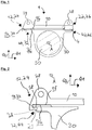
- the bearing arrangement for a brake carrier 1 is shown, the bearing arrangement having a brake means support element 10 and a holding element 30.
- the brake device support element 10 has a first assembly area 12 and a second assembly area 22, the first assembly area 12 forming a first distal end 24 of the brake assembly support element 10 in the negative first transverse direction Q1 and the second assembly area 22 a second distal end 26 of the brake means support element 10 in the positive first transverse direction Q1.
- the first mounting area 12 has a first mounting surface 14 and a second mounting surface 16.
- the first mounting surface 14 is oriented parallel to the first holding surface 34 of the first holding area 32, the first holding area 32 having a first distal end 44 of the holding element 30 and the second holding area 42 form a second distal end 46 of the holding element 30. These distal ends border the holding element 30 in the positive and negative first transverse direction Q1.
- the second holding surface 36 is oriented parallel to the second mounting surface 16. In its middle section - in the direction of the first transverse direction Q1 - the holding element 30 encloses the axis 50 on which the bearing arrangement is fixed.
- the second holding area 42 has a second stop 4.
- the brake means support element 10 has two fixing areas 28, these being formed or arranged in the first assembly area 12 and in the second assembly area 22, respectively.
- the first assembly area 12 is designed such that it surrounds the first holding area 32 by two projections 29 such that it is, inter alia, positively secured against displacement in the positive and negative second transverse direction Q2 and in the positive and negative axial direction A.
- displacement is prevented by the contact of the second mounting surface 16 with the second holding surface 36 and in the negative, second transverse direction by the contact of the third mounting surface 18 with the third holding surface 38.
- FIG. 3 an exploded view of a bearing arrangement for a brake carrier 1 is shown, this exploded view showing the brake means support element 10 shortly before assembly with the holding element 30.
- the brake means support element 10 has two assembly openings 20, each of which is aligned with an assembly hole 40 of the holding element 30.
- the first mounting area 12 is designed as a groove which can be brought into engagement with the first holding area 32 in a manner similar to a feather key, the first mounting surface 14 being oriented in such a way that it can be positively shifted in the direction of the first transverse direction Q1 with the first holding surface 34 prevented.
- FIG. 4 an alternative embodiment of a bearing arrangement for a brake carrier 1 is shown, the brake means support element 10 being clamped together with the holding element 30 via the mounting means 60 in the form of a clamping bracket.
- the first assembly area 12, which is arranged at the first distal end 24 of the brake means support element 10 has a first stop 2, which has an end face in the direction of the axial direction A, which can function as a form-fitting stop face.
- the first mounting surface 14 adjoins the second mounting surface 16 and the third mounting surface 18 at right angles.
- the first holding area 32 has a first holding surface 34 for contact with the first mounting surface 14, a second holding surface 36 for contacting the second mounting surface 16 and a third holding surface 38 for contacting the third mounting surface 18, these surfaces each being parallel to the respective other contact surfaces are oriented.
- the brake means support element 10 has two fixing areas 28, each of which has an opening in the direction of the axial direction A.
- FIG. 5 A bearing arrangement according to the invention for a brake carrier is shown, wherein the first mounting area 12 of the brake means support element 10, in particular by two projections 29, which extend in the direction of the first transverse direction Q1, surrounds the first holding area 32 of the holding element 30 in such a way that at least one relative displacement positively in the positive and negative second transverse direction Q2 and in the positive and negative axial direction A is prevented.
- the mounting means 60 which extends in the direction of the second transverse direction Q2, serves to fasten or brace the second mounting area 22 relative to the second holding area 42.
Landscapes
- Engineering & Computer Science (AREA)
- General Engineering & Computer Science (AREA)
- Mechanical Engineering (AREA)
- Braking Arrangements (AREA)
Claims (13)
- Ensemble formant palier pour un support de frein (1), en particulier pour un véhicule utilitaire, comprenant un élément de retenue (30) et un élément porteur de moyen de freinage (10), l'élément de retenue (30) étant fixé ou pouvant être fixé par coopération de forme, de matière et/ou de force sur un essieu (50) ou sur une partie du train de roulement, l'essieu (50) s'étendant le long d'une direction axiale (A), l'élément porteur de moyen de freinage (10) présentant une première zone de montage (12),
dans lequel
l'élément de retenue (30) présente une première zone de retenue (32), et la première zone de montage (12) est ou peut être amenée en engagement directement ou indirectement avec la première zone de retenue (32) de manière à empêcher par coopération de forme un déplacement le long d'une première direction transversale (Q1) entre l'élément de retenue (30) et l'élément porteur de moyen de freinage (10),
l'élément de retenue (30) présente une deuxième zone de retenue (42), et l'élément porteur de moyen de freinage (10) présente une deuxième zone de montage (22),
la deuxième zone de retenue (42) est ou peut être amenée en engagement par coopération de forme avec la deuxième zone de montage (22) de manière à pouvoir transmettre, entre la deuxième zone de retenue (42) de la deuxième zone de montage (22), une force par coopération de forme en particulier parallèlement à la deuxième direction transversale (Q2),
caractérisé en ce que
la deuxième zone de retenue (42) forme une deuxième extrémité distale (46) de l'élément de retenue (30),
la deuxième zone de montage (22) forme une deuxième zone distale (26) de l'élément porteur de moyen de freinage (10), et
les deuxièmes extrémités distales (26, 46) délimitent l'élément de retenue (30) et l'élément porteur de moyen de freinage (10), en particulier dans le sens de la première direction transversale (Q1). - Ensemble formant palier pour un support de frein (1) selon la revendication 1,
dans lequel la première zone de retenue (32) et/ou la première zone de montage (12) est/sont axialement symétriques par rapport à un plan,
ce plan de symétrie ayant en particulier une normale dans la direction axiale (A). - Ensemble formant palier pour un support de frein (1) selon l'une des revendications précédentes,
dans lequel la première zone de retenue (32) présente une première surface de retenue (34),
la première zone de montage (12) présente une première surface de montage (14), et
la première surface de retenue (34) et la première surface de montage (14) sont en contact direct ou peuvent être mises en contact direct,
de sorte qu'un déplacement dans la première direction transversale (Q1) est empêché ou peut être empêché par le contact direct de la première surface de retenue (34) avec la première surface de montage (14). - Ensemble formant palier pour un support de frein (1) selon l'une des revendications précédentes,
dans lequel la première zone de retenue (32) présente une deuxième surface de retenue (36),
la première zone de montage (12) présente une deuxième surface de montage (16), et
la deuxième surface de retenue (36) est ou peut être amenée en engagement directement avec la deuxième surface de montage (16) de manière à empêcher par coopération de forme un déplacement le long d'une deuxième direction transversale (Q2) entre l'élément de retenue (30) et l'élément porteur de moyen de freinage (10). - Ensemble formant palier pour un support de frein (1) selon l'une des revendications précédentes,
dans lequel la première zone de retenue (32) entoure la première zone de montage (12) au moins localement dans le sens de la première direction transversale (Q1) et/ou dans le sens de la deuxième direction transversale (Q2). - Ensemble formant palier pour un support de frein (1) selon l'une des revendications précédentes,
dans lequel la première zone de retenue (32) entoure au moins localement la première zone de montage (12) dans la direction axiale (A). - Ensemble formant palier pour un support de frein (1) selon l'une des revendications précédentes,
dans lequel l'élément porteur de moyen de freinage (10) présente au moins une ouverture de montage (20), et l'élément de retenue (30) présente au moins un trou de montage (40), et
une ouverture de montage (20) est en alignement avec un trou de montage (40) et est conçue pour recevoir un moyen de montage (60). - Ensemble formant palier pour un support de frein (1) selon la revendication 7,
dans lequel ladite au moins une ouverture de montage (20) et ledit au moins un trou de montage (40) s'étendent sensiblement perpendiculairement à la direction axiale (A). - Ensemble formant palier pour un support de frein (1) selon l'une des revendications précédentes,
dans lequel la première zone de retenue (32) forme une première extrémité distale (44) de l'élément de retenue (30),
la première zone de montage (12) forme une première extrémité distale (24) de l'élément porteur de moyen de freinage (10), et
les premières extrémités distales (24, 44) délimitant l'élément de retenue (30) et l'élément porteur de moyen de freinage (10), en particulier dans le sens de la première direction transversale (Q1). - Ensemble formant palier pour un support de frein (1) selon l'une des revendications précédentes,
dans lequel une première butée (2) est disposée sur la première zone de montage (12) et/ou sur la première zone de retenue (32). - Ensemble formant palier pour un support de frein (1) selon l'une des revendications précédentes,
dans lequel une deuxième butée (4) est disposée sur la deuxième zone de montage (22) et/ou sur la deuxième zone de retenue (42). - Ensemble formant palier pour un support de frein (1) selon l'une des revendications précédentes,
dans lequel l'élément porteur de moyen de freinage (10) présente au moins une zone d'immobilisation (28). - Ensemble formant palier pour un support de frein (1) selon l'une des revendications précédentes,
dans lequel la première zone de montage (12) et/ou la deuxième zone de montage (22) présente(nt) une zone d'immobilisation (28).
Applications Claiming Priority (2)
| Application Number | Priority Date | Filing Date | Title |
|---|---|---|---|
| DE102017126200.8A DE102017126200B4 (de) | 2017-11-09 | 2017-11-09 | Lageranordnung für einen Bremsenträger |
| PCT/EP2018/080475 WO2019092019A1 (fr) | 2017-11-09 | 2018-11-07 | Ensemble formant palier pour un support de frein |
Publications (2)
| Publication Number | Publication Date |
|---|---|
| EP3707403A1 EP3707403A1 (fr) | 2020-09-16 |
| EP3707403B1 true EP3707403B1 (fr) | 2021-03-17 |
Family
ID=64270861
Family Applications (1)
| Application Number | Title | Priority Date | Filing Date |
|---|---|---|---|
| EP18800583.9A Active EP3707403B1 (fr) | 2017-11-09 | 2018-11-07 | Support d'un flasque de frein |
Country Status (4)
| Country | Link |
|---|---|
| US (1) | US11566673B2 (fr) |
| EP (1) | EP3707403B1 (fr) |
| DE (1) | DE102017126200B4 (fr) |
| WO (1) | WO2019092019A1 (fr) |
Family Cites Families (13)
| Publication number | Priority date | Publication date | Assignee | Title |
|---|---|---|---|---|
| GB1287415A (en) * | 1968-10-15 | 1972-08-31 | Dunlop Holdings Ltd | Improvements in and relating to disc brakes |
| US3999635A (en) * | 1975-10-06 | 1976-12-28 | The B. F. Goodrich Company | Disc brake caliper and lining carrier supporting means |
| JPS5261675A (en) * | 1975-11-17 | 1977-05-21 | Toyota Motor Corp | Disc brake |
| DE20021587U1 (de) * | 2000-12-21 | 2001-04-05 | BPW Bergische Achsen KG, 51674 Wiehl | Bremseinrichtung |
| BR0306800A (pt) * | 2002-02-08 | 2004-12-07 | Knorr Bremse Systeme | Freio a disco com dispositivo de reajuste acionado eletricamente |
| DE60304205T2 (de) * | 2003-02-28 | 2006-11-02 | Freni Brembo S.P.A., Curno | Scheibenbremssattel und sattelträgerelement |
| DE102004016826A1 (de) | 2004-04-01 | 2005-10-27 | Daimlerchrysler Ag | Bremsvorrichtung |
| US7673723B2 (en) * | 2005-12-21 | 2010-03-09 | Performance Friction Corporation | Caliper mounting arrangement |
| US20080135352A1 (en) * | 2006-12-12 | 2008-06-12 | Bendix Spicer Foundation Brake Llc | Brake caliper vertical mounting assembly joint arrangement |
| US9506512B2 (en) * | 2013-10-03 | 2016-11-29 | Bendix Spicer Foundation Brake Llc | Brake carrier mounting arrangement |
| DE102014113369A1 (de) * | 2014-09-17 | 2016-03-17 | Knorr-Bremse Systeme für Nutzfahrzeuge GmbH | Anordnung eines Bremsträgers einer Scheibenbremse an einer Fahrzeugachse, Bremsträger und Scheibenbremse |
| WO2017039609A1 (fr) | 2015-08-31 | 2017-03-09 | Compagnie Generale Des Establissements Michelin | Plaque de montage de composant de frein articulée pour correction d'alignement de roue |
| US10385936B2 (en) * | 2017-07-19 | 2019-08-20 | Ford Global Technologies, Llc | Mechanically-keyed non-slip brake joints |
-
2017
- 2017-11-09 DE DE102017126200.8A patent/DE102017126200B4/de active Active
-
2018
- 2018-11-07 US US16/762,377 patent/US11566673B2/en active Active
- 2018-11-07 WO PCT/EP2018/080475 patent/WO2019092019A1/fr not_active Ceased
- 2018-11-07 EP EP18800583.9A patent/EP3707403B1/fr active Active
Non-Patent Citations (1)
| Title |
|---|
| None * |
Also Published As
| Publication number | Publication date |
|---|---|
| WO2019092019A1 (fr) | 2019-05-16 |
| DE102017126200A1 (de) | 2019-05-09 |
| DE102017126200B4 (de) | 2020-12-03 |
| EP3707403A1 (fr) | 2020-09-16 |
| US11566673B2 (en) | 2023-01-31 |
| US20200284309A1 (en) | 2020-09-10 |
Similar Documents
| Publication | Publication Date | Title |
|---|---|---|
| DE3609149C2 (fr) | ||
| EP1730416B1 (fr) | Palier en caoutchouc, notamment pour un organe motopompe de direction assistee | |
| DE69700942T2 (de) | Scheibenbremsvorrichtung | |
| EP3094889A1 (fr) | Axe de satellite à bride vissable | |
| WO2015004080A1 (fr) | Fixation de garniture de frein à disque | |
| EP3606767B1 (fr) | Système d'essieu | |
| EP3172456B1 (fr) | Système de freinage | |
| DE102004045223B3 (de) | Bremsenträger | |
| EP3707403B1 (fr) | Support d'un flasque de frein | |
| EP1735541A1 (fr) | Systeme de freinage | |
| DE102007052280B4 (de) | Richtungsunabhängig ansprechender Geschwindigkeitsbegrenzer | |
| DE102007032318A1 (de) | Elektrischer Aktuator für einen geteilten Kraftfahrzeugstabilisator | |
| WO1994018470A1 (fr) | Dispositif de fixation pour freins a disques | |
| DE102005059247B4 (de) | Bremsvorrichtung | |
| WO2017144448A2 (fr) | Système d'essieu | |
| EP4291794B1 (fr) | Accouplement souple à cardan permettant de transmettre des forces axiales élevées pour des transmissions dans des éoliennes | |
| EP2751439B2 (fr) | Système de freinage d'un frein à tambour | |
| DE102006004487A1 (de) | Scheibenbremse | |
| EP3542082B1 (fr) | Dispositif de rattrapage d'usure pour frein à disque | |
| DE29720240U1 (de) | Drehelastische Kupplung, insbesondere für eine Gelenkwelle | |
| DE102005033078B4 (de) | Festsattelbremse | |
| DE102004014301A1 (de) | Radschraube für ein Kraftfahrzeugrad | |
| EP3199828A1 (fr) | Fixation de garniture de frein à disque de véhicule et serre-flan pour la fixation des garnitures de frein | |
| DE102024204146A1 (de) | Elektromechanische Bremse | |
| EP1561960B1 (fr) | Rotor |
Legal Events
| Date | Code | Title | Description |
|---|---|---|---|
| STAA | Information on the status of an ep patent application or granted ep patent |
Free format text: STATUS: UNKNOWN |
|
| STAA | Information on the status of an ep patent application or granted ep patent |
Free format text: STATUS: THE INTERNATIONAL PUBLICATION HAS BEEN MADE |
|
| PUAI | Public reference made under article 153(3) epc to a published international application that has entered the european phase |
Free format text: ORIGINAL CODE: 0009012 |
|
| STAA | Information on the status of an ep patent application or granted ep patent |
Free format text: STATUS: REQUEST FOR EXAMINATION WAS MADE |
|
| 17P | Request for examination filed |
Effective date: 20200428 |
|
| AK | Designated contracting states |
Kind code of ref document: A1 Designated state(s): AL AT BE BG CH CY CZ DE DK EE ES FI FR GB GR HR HU IE IS IT LI LT LU LV MC MK MT NL NO PL PT RO RS SE SI SK SM TR |
|
| AX | Request for extension of the european patent |
Extension state: BA ME |
|
| RIN1 | Information on inventor provided before grant (corrected) |
Inventor name: HARTMANN, MARK Inventor name: WALLMEIER, STEFAN |
|
| GRAP | Despatch of communication of intention to grant a patent |
Free format text: ORIGINAL CODE: EPIDOSNIGR1 |
|
| STAA | Information on the status of an ep patent application or granted ep patent |
Free format text: STATUS: GRANT OF PATENT IS INTENDED |
|
| DAV | Request for validation of the european patent (deleted) | ||
| DAX | Request for extension of the european patent (deleted) | ||
| INTG | Intention to grant announced |
Effective date: 20201214 |
|
| GRAS | Grant fee paid |
Free format text: ORIGINAL CODE: EPIDOSNIGR3 |
|
| GRAA | (expected) grant |
Free format text: ORIGINAL CODE: 0009210 |
|
| STAA | Information on the status of an ep patent application or granted ep patent |
Free format text: STATUS: THE PATENT HAS BEEN GRANTED |
|
| AK | Designated contracting states |
Kind code of ref document: B1 Designated state(s): AL AT BE BG CH CY CZ DE DK EE ES FI FR GB GR HR HU IE IS IT LI LT LU LV MC MK MT NL NO PL PT RO RS SE SI SK SM TR |
|
| REG | Reference to a national code |
Ref country code: GB Ref legal event code: FG4D Free format text: NOT ENGLISH |
|
| REG | Reference to a national code |
Ref country code: CH Ref legal event code: EP |
|
| REG | Reference to a national code |
Ref country code: DE Ref legal event code: R096 Ref document number: 502018004385 Country of ref document: DE |
|
| REG | Reference to a national code |
Ref country code: IE Ref legal event code: FG4D Free format text: LANGUAGE OF EP DOCUMENT: GERMAN |
|
| REG | Reference to a national code |
Ref country code: AT Ref legal event code: REF Ref document number: 1372515 Country of ref document: AT Kind code of ref document: T Effective date: 20210415 |
|
| REG | Reference to a national code |
Ref country code: LT Ref legal event code: MG9D |
|
| PG25 | Lapsed in a contracting state [announced via postgrant information from national office to epo] |
Ref country code: NO Free format text: LAPSE BECAUSE OF FAILURE TO SUBMIT A TRANSLATION OF THE DESCRIPTION OR TO PAY THE FEE WITHIN THE PRESCRIBED TIME-LIMIT Effective date: 20210617 Ref country code: BG Free format text: LAPSE BECAUSE OF FAILURE TO SUBMIT A TRANSLATION OF THE DESCRIPTION OR TO PAY THE FEE WITHIN THE PRESCRIBED TIME-LIMIT Effective date: 20210617 Ref country code: FI Free format text: LAPSE BECAUSE OF FAILURE TO SUBMIT A TRANSLATION OF THE DESCRIPTION OR TO PAY THE FEE WITHIN THE PRESCRIBED TIME-LIMIT Effective date: 20210317 Ref country code: GR Free format text: LAPSE BECAUSE OF FAILURE TO SUBMIT A TRANSLATION OF THE DESCRIPTION OR TO PAY THE FEE WITHIN THE PRESCRIBED TIME-LIMIT Effective date: 20210618 Ref country code: HR Free format text: LAPSE BECAUSE OF FAILURE TO SUBMIT A TRANSLATION OF THE DESCRIPTION OR TO PAY THE FEE WITHIN THE PRESCRIBED TIME-LIMIT Effective date: 20210317 |
|
| REG | Reference to a national code |
Ref country code: NL Ref legal event code: MP Effective date: 20210317 |
|
| PG25 | Lapsed in a contracting state [announced via postgrant information from national office to epo] |
Ref country code: SE Free format text: LAPSE BECAUSE OF FAILURE TO SUBMIT A TRANSLATION OF THE DESCRIPTION OR TO PAY THE FEE WITHIN THE PRESCRIBED TIME-LIMIT Effective date: 20210317 Ref country code: LV Free format text: LAPSE BECAUSE OF FAILURE TO SUBMIT A TRANSLATION OF THE DESCRIPTION OR TO PAY THE FEE WITHIN THE PRESCRIBED TIME-LIMIT Effective date: 20210317 Ref country code: RS Free format text: LAPSE BECAUSE OF FAILURE TO SUBMIT A TRANSLATION OF THE DESCRIPTION OR TO PAY THE FEE WITHIN THE PRESCRIBED TIME-LIMIT Effective date: 20210317 |
|
| PG25 | Lapsed in a contracting state [announced via postgrant information from national office to epo] |
Ref country code: NL Free format text: LAPSE BECAUSE OF FAILURE TO SUBMIT A TRANSLATION OF THE DESCRIPTION OR TO PAY THE FEE WITHIN THE PRESCRIBED TIME-LIMIT Effective date: 20210317 |
|
| PG25 | Lapsed in a contracting state [announced via postgrant information from national office to epo] |
Ref country code: SM Free format text: LAPSE BECAUSE OF FAILURE TO SUBMIT A TRANSLATION OF THE DESCRIPTION OR TO PAY THE FEE WITHIN THE PRESCRIBED TIME-LIMIT Effective date: 20210317 Ref country code: LT Free format text: LAPSE BECAUSE OF FAILURE TO SUBMIT A TRANSLATION OF THE DESCRIPTION OR TO PAY THE FEE WITHIN THE PRESCRIBED TIME-LIMIT Effective date: 20210317 Ref country code: CZ Free format text: LAPSE BECAUSE OF FAILURE TO SUBMIT A TRANSLATION OF THE DESCRIPTION OR TO PAY THE FEE WITHIN THE PRESCRIBED TIME-LIMIT Effective date: 20210317 Ref country code: EE Free format text: LAPSE BECAUSE OF FAILURE TO SUBMIT A TRANSLATION OF THE DESCRIPTION OR TO PAY THE FEE WITHIN THE PRESCRIBED TIME-LIMIT Effective date: 20210317 |
|
| PG25 | Lapsed in a contracting state [announced via postgrant information from national office to epo] |
Ref country code: IS Free format text: LAPSE BECAUSE OF FAILURE TO SUBMIT A TRANSLATION OF THE DESCRIPTION OR TO PAY THE FEE WITHIN THE PRESCRIBED TIME-LIMIT Effective date: 20210717 Ref country code: PL Free format text: LAPSE BECAUSE OF FAILURE TO SUBMIT A TRANSLATION OF THE DESCRIPTION OR TO PAY THE FEE WITHIN THE PRESCRIBED TIME-LIMIT Effective date: 20210317 Ref country code: PT Free format text: LAPSE BECAUSE OF FAILURE TO SUBMIT A TRANSLATION OF THE DESCRIPTION OR TO PAY THE FEE WITHIN THE PRESCRIBED TIME-LIMIT Effective date: 20210719 Ref country code: RO Free format text: LAPSE BECAUSE OF FAILURE TO SUBMIT A TRANSLATION OF THE DESCRIPTION OR TO PAY THE FEE WITHIN THE PRESCRIBED TIME-LIMIT Effective date: 20210317 Ref country code: SK Free format text: LAPSE BECAUSE OF FAILURE TO SUBMIT A TRANSLATION OF THE DESCRIPTION OR TO PAY THE FEE WITHIN THE PRESCRIBED TIME-LIMIT Effective date: 20210317 |
|
| REG | Reference to a national code |
Ref country code: DE Ref legal event code: R097 Ref document number: 502018004385 Country of ref document: DE |
|
| PLBE | No opposition filed within time limit |
Free format text: ORIGINAL CODE: 0009261 |
|
| STAA | Information on the status of an ep patent application or granted ep patent |
Free format text: STATUS: NO OPPOSITION FILED WITHIN TIME LIMIT |
|
| PG25 | Lapsed in a contracting state [announced via postgrant information from national office to epo] |
Ref country code: ES Free format text: LAPSE BECAUSE OF FAILURE TO SUBMIT A TRANSLATION OF THE DESCRIPTION OR TO PAY THE FEE WITHIN THE PRESCRIBED TIME-LIMIT Effective date: 20210317 Ref country code: DK Free format text: LAPSE BECAUSE OF FAILURE TO SUBMIT A TRANSLATION OF THE DESCRIPTION OR TO PAY THE FEE WITHIN THE PRESCRIBED TIME-LIMIT Effective date: 20210317 Ref country code: AL Free format text: LAPSE BECAUSE OF FAILURE TO SUBMIT A TRANSLATION OF THE DESCRIPTION OR TO PAY THE FEE WITHIN THE PRESCRIBED TIME-LIMIT Effective date: 20210317 |
|
| 26N | No opposition filed |
Effective date: 20211220 |
|
| PG25 | Lapsed in a contracting state [announced via postgrant information from national office to epo] |
Ref country code: IT Free format text: LAPSE BECAUSE OF FAILURE TO SUBMIT A TRANSLATION OF THE DESCRIPTION OR TO PAY THE FEE WITHIN THE PRESCRIBED TIME-LIMIT Effective date: 20210317 |
|
| PG25 | Lapsed in a contracting state [announced via postgrant information from national office to epo] |
Ref country code: IS Free format text: LAPSE BECAUSE OF FAILURE TO SUBMIT A TRANSLATION OF THE DESCRIPTION OR TO PAY THE FEE WITHIN THE PRESCRIBED TIME-LIMIT Effective date: 20210717 |
|
| PG25 | Lapsed in a contracting state [announced via postgrant information from national office to epo] |
Ref country code: MC Free format text: LAPSE BECAUSE OF FAILURE TO SUBMIT A TRANSLATION OF THE DESCRIPTION OR TO PAY THE FEE WITHIN THE PRESCRIBED TIME-LIMIT Effective date: 20210317 |
|
| REG | Reference to a national code |
Ref country code: CH Ref legal event code: PL |
|
| PG25 | Lapsed in a contracting state [announced via postgrant information from national office to epo] |
Ref country code: LU Free format text: LAPSE BECAUSE OF NON-PAYMENT OF DUE FEES Effective date: 20211107 Ref country code: BE Free format text: LAPSE BECAUSE OF NON-PAYMENT OF DUE FEES Effective date: 20211130 |
|
| REG | Reference to a national code |
Ref country code: BE Ref legal event code: MM Effective date: 20211130 |
|
| PG25 | Lapsed in a contracting state [announced via postgrant information from national office to epo] |
Ref country code: LI Free format text: LAPSE BECAUSE OF NON-PAYMENT OF DUE FEES Effective date: 20211130 Ref country code: CH Free format text: LAPSE BECAUSE OF NON-PAYMENT OF DUE FEES Effective date: 20211130 |
|
| PG25 | Lapsed in a contracting state [announced via postgrant information from national office to epo] |
Ref country code: IE Free format text: LAPSE BECAUSE OF NON-PAYMENT OF DUE FEES Effective date: 20211107 |
|
| PGFP | Annual fee paid to national office [announced via postgrant information from national office to epo] |
Ref country code: GB Payment date: 20221123 Year of fee payment: 5 |
|
| P01 | Opt-out of the competence of the unified patent court (upc) registered |
Effective date: 20230505 |
|
| PG25 | Lapsed in a contracting state [announced via postgrant information from national office to epo] |
Ref country code: CY Free format text: LAPSE BECAUSE OF FAILURE TO SUBMIT A TRANSLATION OF THE DESCRIPTION OR TO PAY THE FEE WITHIN THE PRESCRIBED TIME-LIMIT Effective date: 20210317 |
|
| PG25 | Lapsed in a contracting state [announced via postgrant information from national office to epo] |
Ref country code: HU Free format text: LAPSE BECAUSE OF FAILURE TO SUBMIT A TRANSLATION OF THE DESCRIPTION OR TO PAY THE FEE WITHIN THE PRESCRIBED TIME-LIMIT; INVALID AB INITIO Effective date: 20181107 |
|
| PG25 | Lapsed in a contracting state [announced via postgrant information from national office to epo] |
Ref country code: SI Free format text: LAPSE BECAUSE OF FAILURE TO SUBMIT A TRANSLATION OF THE DESCRIPTION OR TO PAY THE FEE WITHIN THE PRESCRIBED TIME-LIMIT Effective date: 20210317 |
|
| PG25 | Lapsed in a contracting state [announced via postgrant information from national office to epo] |
Ref country code: MK Free format text: LAPSE BECAUSE OF FAILURE TO SUBMIT A TRANSLATION OF THE DESCRIPTION OR TO PAY THE FEE WITHIN THE PRESCRIBED TIME-LIMIT Effective date: 20210317 |
|
| PG25 | Lapsed in a contracting state [announced via postgrant information from national office to epo] |
Ref country code: TR Free format text: LAPSE BECAUSE OF FAILURE TO SUBMIT A TRANSLATION OF THE DESCRIPTION OR TO PAY THE FEE WITHIN THE PRESCRIBED TIME-LIMIT Effective date: 20210317 |
|
| GBPC | Gb: european patent ceased through non-payment of renewal fee |
Effective date: 20231107 |
|
| PG25 | Lapsed in a contracting state [announced via postgrant information from national office to epo] |
Ref country code: MT Free format text: LAPSE BECAUSE OF FAILURE TO SUBMIT A TRANSLATION OF THE DESCRIPTION OR TO PAY THE FEE WITHIN THE PRESCRIBED TIME-LIMIT Effective date: 20210317 |
|
| PG25 | Lapsed in a contracting state [announced via postgrant information from national office to epo] |
Ref country code: GB Free format text: LAPSE BECAUSE OF NON-PAYMENT OF DUE FEES Effective date: 20231107 |
|
| PG25 | Lapsed in a contracting state [announced via postgrant information from national office to epo] |
Ref country code: GB Free format text: LAPSE BECAUSE OF NON-PAYMENT OF DUE FEES Effective date: 20231107 |
|
| REG | Reference to a national code |
Ref country code: AT Ref legal event code: MM01 Ref document number: 1372515 Country of ref document: AT Kind code of ref document: T Effective date: 20231107 |
|
| PG25 | Lapsed in a contracting state [announced via postgrant information from national office to epo] |
Ref country code: AT Free format text: LAPSE BECAUSE OF NON-PAYMENT OF DUE FEES Effective date: 20231107 |
|
| PG25 | Lapsed in a contracting state [announced via postgrant information from national office to epo] |
Ref country code: AT Free format text: LAPSE BECAUSE OF NON-PAYMENT OF DUE FEES Effective date: 20231107 |
|
| PGFP | Annual fee paid to national office [announced via postgrant information from national office to epo] |
Ref country code: DE Payment date: 20250819 Year of fee payment: 8 |
|
| PGFP | Annual fee paid to national office [announced via postgrant information from national office to epo] |
Ref country code: FR Payment date: 20251120 Year of fee payment: 8 |
|
| PGFP | Annual fee paid to national office [announced via postgrant information from national office to epo] |
Ref country code: AT Payment date: 20260410 Year of fee payment: 5 |