EP3709106A1 - Mise en sécurité d'une machine - Google Patents
Mise en sécurité d'une machine Download PDFInfo
- Publication number
- EP3709106A1 EP3709106A1 EP19161892.5A EP19161892A EP3709106A1 EP 3709106 A1 EP3709106 A1 EP 3709106A1 EP 19161892 A EP19161892 A EP 19161892A EP 3709106 A1 EP3709106 A1 EP 3709106A1
- Authority
- EP
- European Patent Office
- Prior art keywords
- safe
- secure
- data
- safety
- security system
- Prior art date
- Legal status (The legal status is an assumption and is not a legal conclusion. Google has not performed a legal analysis and makes no representation as to the accuracy of the status listed.)
- Granted
Links
Images
Classifications
-
- F—MECHANICAL ENGINEERING; LIGHTING; HEATING; WEAPONS; BLASTING
- F16—ENGINEERING ELEMENTS AND UNITS; GENERAL MEASURES FOR PRODUCING AND MAINTAINING EFFECTIVE FUNCTIONING OF MACHINES OR INSTALLATIONS; THERMAL INSULATION IN GENERAL
- F16P—SAFETY DEVICES IN GENERAL; SAFETY DEVICES FOR PRESSES
- F16P3/00—Safety devices acting in conjunction with the control or operation of a machine; Control arrangements requiring the simultaneous use of two or more parts of the body
- F16P3/12—Safety devices acting in conjunction with the control or operation of a machine; Control arrangements requiring the simultaneous use of two or more parts of the body with means, e.g. feelers, which in case of the presence of a body part of a person in or near the danger zone influence the control or operation of the machine
- F16P3/14—Safety devices acting in conjunction with the control or operation of a machine; Control arrangements requiring the simultaneous use of two or more parts of the body with means, e.g. feelers, which in case of the presence of a body part of a person in or near the danger zone influence the control or operation of the machine the means being photocells or other devices sensitive without mechanical contact
-
- B—PERFORMING OPERATIONS; TRANSPORTING
- B25—HAND TOOLS; PORTABLE POWER-DRIVEN TOOLS; MANIPULATORS
- B25J—MANIPULATORS; CHAMBERS PROVIDED WITH MANIPULATION DEVICES
- B25J9/00—Program-controlled manipulators
- B25J9/16—Program controls
- B25J9/1674—Program controls characterised by safety, monitoring, diagnostic
- B25J9/1676—Avoiding collision or forbidden zones
-
- G—PHYSICS
- G05—CONTROLLING; REGULATING
- G05B—CONTROL OR REGULATING SYSTEMS IN GENERAL; FUNCTIONAL ELEMENTS OF SUCH SYSTEMS; MONITORING OR TESTING ARRANGEMENTS FOR SUCH SYSTEMS OR ELEMENTS
- G05B9/00—Safety arrangements
- G05B9/02—Safety arrangements electric
- G05B9/03—Safety arrangements electric with multiple-channel loop, i.e. redundant control systems
-
- B—PERFORMING OPERATIONS; TRANSPORTING
- B25—HAND TOOLS; PORTABLE POWER-DRIVEN TOOLS; MANIPULATORS
- B25J—MANIPULATORS; CHAMBERS PROVIDED WITH MANIPULATION DEVICES
- B25J9/00—Program-controlled manipulators
- B25J9/16—Program controls
- B25J9/1674—Program controls characterised by safety, monitoring, diagnostic
-
- F—MECHANICAL ENGINEERING; LIGHTING; HEATING; WEAPONS; BLASTING
- F16—ENGINEERING ELEMENTS AND UNITS; GENERAL MEASURES FOR PRODUCING AND MAINTAINING EFFECTIVE FUNCTIONING OF MACHINES OR INSTALLATIONS; THERMAL INSULATION IN GENERAL
- F16P—SAFETY DEVICES IN GENERAL; SAFETY DEVICES FOR PRESSES
- F16P3/00—Safety devices acting in conjunction with the control or operation of a machine; Control arrangements requiring the simultaneous use of two or more parts of the body
- F16P3/12—Safety devices acting in conjunction with the control or operation of a machine; Control arrangements requiring the simultaneous use of two or more parts of the body with means, e.g. feelers, which in case of the presence of a body part of a person in or near the danger zone influence the control or operation of the machine
- F16P3/14—Safety devices acting in conjunction with the control or operation of a machine; Control arrangements requiring the simultaneous use of two or more parts of the body with means, e.g. feelers, which in case of the presence of a body part of a person in or near the danger zone influence the control or operation of the machine the means being photocells or other devices sensitive without mechanical contact
- F16P3/144—Safety devices acting in conjunction with the control or operation of a machine; Control arrangements requiring the simultaneous use of two or more parts of the body with means, e.g. feelers, which in case of the presence of a body part of a person in or near the danger zone influence the control or operation of the machine the means being photocells or other devices sensitive without mechanical contact using light grids
-
- G—PHYSICS
- G05—CONTROLLING; REGULATING
- G05B—CONTROL OR REGULATING SYSTEMS IN GENERAL; FUNCTIONAL ELEMENTS OF SUCH SYSTEMS; MONITORING OR TESTING ARRANGEMENTS FOR SUCH SYSTEMS OR ELEMENTS
- G05B19/00—Program-control systems
- G05B19/02—Program-control systems electric
- G05B19/04—Program control other than numerical control, i.e. in sequence controllers or logic controllers
- G05B19/042—Program control other than numerical control, i.e. in sequence controllers or logic controllers using digital processors
- G05B19/0428—Safety, monitoring
-
- G—PHYSICS
- G05—CONTROLLING; REGULATING
- G05B—CONTROL OR REGULATING SYSTEMS IN GENERAL; FUNCTIONAL ELEMENTS OF SUCH SYSTEMS; MONITORING OR TESTING ARRANGEMENTS FOR SUCH SYSTEMS OR ELEMENTS
- G05B19/00—Program-control systems
- G05B19/02—Program-control systems electric
- G05B19/18—Numerical control [NC], i.e. automatically operating machines, in particular machine tools, e.g. in a manufacturing environment, so as to execute positioning, movement or co-ordinated operations by means of program data in numerical form
- G05B19/406—Numerical control [NC], i.e. automatically operating machines, in particular machine tools, e.g. in a manufacturing environment, so as to execute positioning, movement or co-ordinated operations by means of program data in numerical form characterised by monitoring or safety
- G05B19/4061—Avoiding collision or forbidden zones
-
- G—PHYSICS
- G05—CONTROLLING; REGULATING
- G05D—SYSTEMS FOR CONTROLLING OR REGULATING NON-ELECTRIC VARIABLES
- G05D1/00—Control of position, course, altitude or attitude of land, water, air or space vehicles, e.g. using automatic pilots
- G05D1/02—Control of position or course in two dimensions
- G05D1/021—Control of position or course in two dimensions specially adapted to land vehicles
- G05D1/0212—Control of position or course in two dimensions specially adapted to land vehicles with means for defining a desired trajectory
- G05D1/0214—Control of position or course in two dimensions specially adapted to land vehicles with means for defining a desired trajectory in accordance with safety or protection criteria, e.g. avoiding hazardous areas
-
- G—PHYSICS
- G05—CONTROLLING; REGULATING
- G05D—SYSTEMS FOR CONTROLLING OR REGULATING NON-ELECTRIC VARIABLES
- G05D1/00—Control of position, course, altitude or attitude of land, water, air or space vehicles, e.g. using automatic pilots
- G05D1/20—Control system inputs
- G05D1/24—Arrangements for determining position or orientation
- G05D1/242—Means based on the reflection of waves generated by the vehicle
-
- G—PHYSICS
- G05—CONTROLLING; REGULATING
- G05D—SYSTEMS FOR CONTROLLING OR REGULATING NON-ELECTRIC VARIABLES
- G05D1/00—Control of position, course, altitude or attitude of land, water, air or space vehicles, e.g. using automatic pilots
- G05D1/60—Intended control result
- G05D1/617—Safety or protection, e.g. defining protection zones around obstacles or avoiding hazards
- G05D1/622—Obstacle avoidance
-
- G—PHYSICS
- G05—CONTROLLING; REGULATING
- G05D—SYSTEMS FOR CONTROLLING OR REGULATING NON-ELECTRIC VARIABLES
- G05D1/00—Control of position, course, altitude or attitude of land, water, air or space vehicles, e.g. using automatic pilots
- G05D1/80—Arrangements for reacting to or preventing system or operator failure
- G05D1/86—Monitoring the performance of the system, e.g. alarm or diagnosis modules
-
- G—PHYSICS
- G05—CONTROLLING; REGULATING
- G05B—CONTROL OR REGULATING SYSTEMS IN GENERAL; FUNCTIONAL ELEMENTS OF SUCH SYSTEMS; MONITORING OR TESTING ARRANGEMENTS FOR SUCH SYSTEMS OR ELEMENTS
- G05B2219/00—Program-control systems
- G05B2219/20—Pc systems
- G05B2219/24—Pc safety
- G05B2219/24008—Safety integrity level, safety integrated systems SIL SIS
-
- G—PHYSICS
- G05—CONTROLLING; REGULATING
- G05B—CONTROL OR REGULATING SYSTEMS IN GENERAL; FUNCTIONAL ELEMENTS OF SUCH SYSTEMS; MONITORING OR TESTING ARRANGEMENTS FOR SUCH SYSTEMS OR ELEMENTS
- G05B2219/00—Program-control systems
- G05B2219/20—Pc systems
- G05B2219/24—Pc safety
- G05B2219/24189—Redundant processors monitor same point, common parameters
-
- G—PHYSICS
- G05—CONTROLLING; REGULATING
- G05B—CONTROL OR REGULATING SYSTEMS IN GENERAL; FUNCTIONAL ELEMENTS OF SUCH SYSTEMS; MONITORING OR TESTING ARRANGEMENTS FOR SUCH SYSTEMS OR ELEMENTS
- G05B2219/00—Program-control systems
- G05B2219/30—Nc systems
- G05B2219/40—Robotics, robotics mapping to robotics vision
- G05B2219/40548—Compare measured distances to obstacle with model of environment
-
- G—PHYSICS
- G05—CONTROLLING; REGULATING
- G05B—CONTROL OR REGULATING SYSTEMS IN GENERAL; FUNCTIONAL ELEMENTS OF SUCH SYSTEMS; MONITORING OR TESTING ARRANGEMENTS FOR SUCH SYSTEMS OR ELEMENTS
- G05B2219/00—Program-control systems
- G05B2219/30—Nc systems
- G05B2219/40—Robotics, robotics mapping to robotics vision
- G05B2219/40613—Camera, laser scanner on end effector, hand eye manipulator, local
-
- G—PHYSICS
- G05—CONTROLLING; REGULATING
- G05D—SYSTEMS FOR CONTROLLING OR REGULATING NON-ELECTRIC VARIABLES
- G05D2105/00—Specific applications of the controlled vehicles
- G05D2105/20—Specific applications of the controlled vehicles for transportation
- G05D2105/28—Specific applications of the controlled vehicles for transportation of freight
-
- G—PHYSICS
- G05—CONTROLLING; REGULATING
- G05D—SYSTEMS FOR CONTROLLING OR REGULATING NON-ELECTRIC VARIABLES
- G05D2107/00—Specific environments of the controlled vehicles
- G05D2107/70—Industrial sites, e.g. warehouses or factories
-
- G—PHYSICS
- G05—CONTROLLING; REGULATING
- G05D—SYSTEMS FOR CONTROLLING OR REGULATING NON-ELECTRIC VARIABLES
- G05D2109/00—Types of controlled vehicles
- G05D2109/10—Land vehicles
-
- G—PHYSICS
- G05—CONTROLLING; REGULATING
- G05D—SYSTEMS FOR CONTROLLING OR REGULATING NON-ELECTRIC VARIABLES
- G05D2111/00—Details of signals used for control of position, course, altitude or attitude of land, water, air or space vehicles
- G05D2111/10—Optical signals
- G05D2111/17—Coherent light, e.g. laser signals
Definitions
- the invention relates to a safety system and a method for protecting a machine according to the preamble of claims 1 and 14, respectively.
- a generic safety system uses one or more sensors to monitor the environment of a machine and to put it in a safe state in good time in the event of impending danger.
- a sensor that is often used for this is a laser scanner.
- a light beam generated by a laser periodically sweeps over a monitored area with the aid of a deflection unit. The light is reflected on objects in the monitored area and evaluated in the laser scanner.
- the angular position of the object is determined from the angular position of the deflection unit and the distance of the object from the laser scanner is also deduced from the time of flight using the speed of light.
- the location of an object in the monitoring area is recorded in two-dimensional polar coordinates.
- the third spatial coordinate can also be detected by a relative movement in the transverse direction, for example by a further degree of freedom of movement of the deflection unit in the laser scanner or by moving the object relative to the laser scanner.
- the laser scanner monitors a protective field that the operating personnel must not enter while the machine is in operation. If the sensor detects an impermissible protective field intervention, for example an operator's leg, it triggers an emergency stop of the machine.
- Sensors used in safety technology must work particularly reliably and therefore meet high safety requirements, for example the EN13849 standard for machine safety and the EN61496 device standard for electro-sensitive protective devices (ESPE).
- ESE electro-sensitive protective devices
- a safety laser scanner according to such standards is, for example, from DE 43 40 756 A1 known.
- the protective field evaluation of a laser scanner is a typical example of a discrepancy in the information content between the recorded sensor information and the safe output variable.
- a wealth of high-quality sensor information is recorded internally, in the example of the laser scanner the contour of all scanned objects, with other sensors it can be two- or three-dimensional image data or other sensor data.
- this sensor information is already filtered in the sensor and heavily compressed in accordance with safety regulations, usually up to a binary switching signal for a machine control, which, if necessary, puts the machine in a safe state.
- the binary switching signal is safe, but contains almost nothing of the initial sensor information. In this way, mainly simple safety functions can be implemented, such as the initial example of monitoring configured protective fields.
- the non-compressed sensor data with a high information content is not passed on or only passed on via non-secure data interfaces in order to implement additional automation functions. This means that no safety applications are possible, since the transfer of the sensor data and the subsequent evaluation do not meet the requirements of the safety standards mentioned.
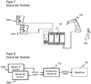
- Safe sensors 100a-b in this example safety laser scanners, are connected to a safety controller 102 connected.
- the safe switching signals of the safety laser scanners 100a-b are linked there. If a person 106 in the vicinity of the monitored machine 104, here an industrial robot, is at risk, a safety signal is output to the machine 104 in order to put the machine 104 in a safe state in good time.
- Safety components are used throughout, that is to say safe sensors 100a-b, a safety controller 102 and safe signal paths. To be on the safe side, separate error control measures are implemented everywhere, so that possible safety-critical errors along the signal chain can be avoided or controlled.
- the EP 2 395 372 B1 discloses an arrangement of several safety laser scanners that are connected together to a safety controller. In addition to the protective fields, automation fields are monitored, with certain interventions in the automation fields triggering a switchover of the protective field configuration.
- the safety-related communication of the safety laser scanners is consequently still limited to binary protective field violations, so this is an example of the to Figure 6 and 7th is the conventional approach discussed.
- WO 2010/094466 A1 From the WO 2010/094466 A1 a method and a device for creating a user program for a safety controller are known. It can be configured which part of the program variable is safety-relevant and which is not, and accordingly there is a first program part for fail-safe processing and a second program part for non-fail-safe processing. But that does not solve the problem of insufficient computing capacity in the safety control.
- the non-failsafe processing of necessity remains simple due to limited resources. In addition, as intended, it no longer plays a role in the security concept and therefore does not contribute to its flexibility and complexity.
- the safety system comprises at least one safe sensor that detects the machine or an area with reference to the machine, such as its surroundings or an access route, and generates safe data or signals from this sensor information.
- the term is to be understood in the sense of the standards mentioned in the introduction or comparable standards, so measures have been taken to control errors up to a specified security level.
- the safe sensor and / or at least one not Safe sensors also generate non-safe data such as raw data, point clouds or the like. Not safe is the opposite term too safe, for non-safe devices, transmission paths, evaluations and the like, the stated requirements for fail-safe security are therefore not met.
- An unsafe evaluation processes the unsafe data.
- This is a function branch also for complex and flexible evaluations.
- the safe data can optionally be included, but in the function branch it is only to be understood as an additional part of the non-safe data.
- a safe evaluation checks the result of the unsafe evaluation with the help of the safe data.
- This safe test or plausibility branch establishes a required level of security for the overall system including the functional branch. According to the safety standards mentioned in the introduction, this corresponds to an accepted single-channel safety architecture with testing.
- the invention is based on the basic idea of using safe data for testing, the information content of which is low compared to the non-safe data and the evaluation result found therefrom in the functional branch of the non-safe evaluation.
- the reliable data are therefore available with less accuracy and / or less often than the evaluation result.
- the secure data form a kind of grid around the evaluation results, with which outbreaks that are too large can be recognized, but which would not be sufficient to verify the evaluation results at any time and with any precision. This is not just about tolerances in a comparison, the safe data is rather missing a dedicated information depth corresponding to the evaluation results from the non-safe data according to the safe evaluation.
- the safe evaluation has evaluated the sensor information with a very specific aim to the safe data and in doing so has thinned or condensed its information content considerably.
- the secure data therefore in no way replace the non-secure evaluation, there is not simply redundancy.
- the invention has the advantage that complex safety functions can also be implemented and flexibly adapted. It is not just a conventional sensor data fusion at the level of simple, safe signals. Rather, there is the possibility first collect sensor information from various safe and / or non-safe sensors and then implement a combined safety function. This is based on available hardware components, so there is no need to wait for the development of more powerful safety interfaces for the transfer of complex, secure data, nor for safety controls with significantly more computing power. With the architecture of a security system according to the invention, the entire spectrum of security levels can be mapped, for example performance levels PL a to PL d.
- the sensors are preferably all or at least partially optoelectronic sensors. This applies to both the safe and the non-safe sensors, because they allow an area around the machine to be monitored particularly well.
- the safe evaluation unit is preferably designed to generate a safety signal to the machine if the evaluation result is not plausible. In this case, the test has failed due to the plausibility check branch, and the non-reliable evaluation has accordingly been recognized as unreliable or an error has been discovered. It is conceivable to still tolerate this under specified criteria, for example to wait for the next test cycle. At this point at the latest, however, the safety system outputs a safety signal to the machine, which then changes to a safe state, for example stops, slows down or evades.
- the non-safe evaluation unit is preferably designed to generate control signals to the machine, in particular to protect the machine.
- the activation of the machine by the non-secure evaluation unit expressly includes safeguarding as a possibility if the result of processing the non-secure data results in this requirement.
- the risk of an undetected error in the non-secure evaluation unit is limited to the scope of the lack of accuracy and / or the duration between two tests. Achieved with it the security system as a whole and including the non-secure evaluation unit viewed in isolation, a specified security level.
- the safety system preferably has a safety control with the safe evaluation unit.
- the safe evaluation unit thus forms its own device.
- the safe sensor transfers the safe data to the safety controller.
- the safety control is safe, but has only a limited range of functions or limited storage and computing capacity and bandwidth of the data interfaces.
- implementation as a function block in the safe sensor is conceivable.
- the security system preferably has a computer unit with the non-secure evaluation unit.
- the computer unit is also a separate device, but not a safety controller, so it is not designed to be safe. Examples are a non-safe controller or standard controller, but also an industrial computer with CPU and / or GPU and a computer network including a cloud.
- the non-secure data are transferred to the computer unit, be it from the secure sensor or the non-secure sensor.
- the computer unit is preferably designed for complex evaluations, has a high range of functions and large storage and computing capacities as well as bandwidth of the data interfaces. As an alternative to a separate computer unit, implementation as a function block in the unsafe or also the safe sensor is conceivable.
- the secure evaluation unit and the non-secure evaluation unit are implemented in a common device.
- this is not the preferred solution, as individual hardware modules can be designed more specifically for their respective tasks.
- the secure data preferably have at least one binary object detection signal. Even more preferably, the secure data consist exclusively of at least one binary object detection signal.
- This is a common output variable of a safe sensor, which in conventional applications is output directly or indirectly after being linked in an interposed safety controller as a safety signal to the machine.
- the binary object detection signal is used by the safe evaluation unit for testing and thus acts at most indirectly as a security signal.
- the secure data preferably have information as to whether a protective field has been violated and what it is. This is usually done in the form of binary object detection signals, but is in principle also possible in a different data format. If only one protective field is monitored, its identity is automatically known without the safe data having to contain any information. If there are several protective fields, several outputs are used as a transmission path or a protocol that allows the identity of the protective fields to be recognized through specific time slots or other coding.
- the safe sensor is preferably designed as a safety laser scanner. If there are several safe sensors, at least one of them is a safety laser scanner, and in some embodiments all of the safe sensors are even safety laser scanners. These are very well-proven sensors in security technology with a large detection area, which can also serve as a source for high-quality, unsafe data in the form of scan data or object contours or point clouds. Safety laser scanners are particularly able to detect violations of one or more configured protective fields and to output corresponding safe data, for example in the form of binary switching signals. Protective field monitoring is also conceivable with other safe optoelectronic sensors, for example with light grids and two- or three-dimensional cameras, as well as with other sensors such as capacitive sensors or step mats.
- the non-secure evaluation unit is preferably designed to determine the distance between an object and the machine. With this distance, in particular a distance-based protection of the machine can take place, which is then protected when an object comes too close to the machine.
- the speed is preferably also determined (speed-and-separation monitoring).
- the distance between any objects is not monitored, but people or even body parts are recognized and at least some other known objects are also permitted close to the machine. It should be pointed out again that this security-relevant evaluation takes place in the non-secure evaluation unit. The security arises through the verification by means of the secure evaluation unit.
- the safe sensor is preferably designed to monitor a grid made up of a plurality of protective fields, the safe data relating to the identity of an injured person Protective field have a safe position information.
- safe comparison data suitable for distance monitoring are recorded. Thanks to the grid of safely monitored protective fields, the position of an object in the vicinity of the machine is reliably recorded with the accuracy of the grid.
- This position information is coarser than that of the distance monitoring in the non-safe evaluation unit and is output by means of a small amount of safe data, in particular binary object detection signals. However, this is sufficient to detect errors in the unsafe distance monitoring.
- the secure evaluation unit is preferably designed to check the evaluation result of the non-secure evaluation unit at a point in time at which the identity of an infringed protective field changes.
- the test therefore takes place at very specific points in time, with these tests specifically triggered by changes in the detected protective field violations supplementing or replacing cyclical tests depending on the embodiment.
- the intervening object must be on its edge. Particularly if at the same time an earlier protective field violation of an adjacent protective field is no longer present, at this point in time the object position is even better known with high accuracy than the grid of the protective fields.
- the non-safe evaluation unit is preferably designed to navigate a vehicle, preferably an autonomous vehicle (AGV, Automated Guided Vehicle). Depending on the embodiment, this includes self-localization, path finding, environment detection and protection of the vehicle.
- AGV Automated Guided Vehicle
- the security system preferably travels along with at least some of the sensors, additional stationary sensors and, for example, non-secure evaluation in a cloud outside the vehicle being conceivable.
- SLAM algorithms Simultaneous Localization and Mapping
- the safe data preferably have position information at at least one reference position, in particular in that the safe sensor monitors reference protective fields.
- these are suitable safe data for testing the non-safe evaluation unit.
- the navigation that is not reliably calculated must at least reproduce the reference positions, the security level being predefined, among other things, by the frequency of reference positions.
- Reference positions are preferably obtained in that reference protective fields at known positions are checked for damage by the safe sensor.
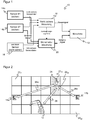
- FIG. 1 shows a schematic block diagram of a safety system 10 for protecting a machine 12, such as a robot, a vehicle or some other mostly complex machine.
- At least one safe sensor in the example there are two safe sensors 14a-b, monitors an area assigned to the machine 12, such as its surroundings or an access route.
- a non-safe sensor 16 can optionally be provided.
- the terms safe and not safe continue to be so understand that the corresponding components, transmission paths and evaluations meet or do not meet the standardized criteria for security mentioned in the introduction.
- the sensors are preferably optoelectronic sensors, such as laser scanners or cameras, but can also be based at least partially on a different sensor principle.
- the safety system has a non-safe control 18 and a safety control 20. These are preferably separate hardware modules, as shown. Alternatively, there could be at least some of the function blocks in the sensors 14, 16 or a common controller 18, 20. The division into secure and non-secure paths would remain in place.
- the non-safe controller 18 preferably has a high computing power and flexibility and is able to communicate and process large amounts of data. For example, it is a non-safe standard controller or a CPU or GPU in an industrial computer. An edge computing infrastructure or a cloud solution are also conceivable. Since processing does not have to be secure, machine learning approaches are also possible, such as deep learning and all variants of neural networks.
- the non-safe control 18 receives and processes non-safe sensor data from the non-safe sensor 16, if present, alternatively or additionally also non-safe data from a safe sensor 14a-b.
- the non-secure sensor data are typically complex and extensive, such as images, point clouds or scan data.
- the non-safe control 18 forms a functional branch in which complex evaluations of large amounts of sensor data take place. Standard hardware can be used for this because no or at most low security requirements have to be met.
- the safety controller 20 is designed to be safe through two-channel connections, processing paths and corresponding evaluations. In return, it offers comparatively simple evaluation options, interfaces with a small bandwidth mostly only for binary signals and limited storage and computing capacities.
- the safety controller 20 receives safe data from the safe sensors 14a-b.
- the safe sensors 14a-b have already considerably reduced or compressed the original sensor data through internal safe evaluation. Only a binary safe signal is regularly output (OSSD, Output Signal Switching Device), in some cases several of them, in order to provide information about which of several protective fields monitored in parallel has been violated.
- the safety controller 20 also receives non-safe data from the non-safe sensor 16, with the additional redundancy being able to increase the level of safety.
- the safety controller 20 forms a test or plausibility branch for the non-safe controller 18.
- the non-safe controller 18 transfers an evaluation result to the safety controller.
- the evaluation result can, but does not have to be the desired output variable of the non-safe evaluation, but is possibly only part of it or even a specific test value that is generated for the safety controller 20 during the actual evaluation.
- the safety controller 20 now uses the safe data to check whether the evaluation result corresponds to your expectations, and thus reveals possible errors in the non-safe controller 18. Examples of the evaluation result transferred for test purposes and the secure data on the basis of which the evaluation result is tested are given below.
- the expectation is in Figure 1 derived from the safe signals of the safe sensors 14a-b.
- safe system data for example safe position information of the machine 12 or process information such as certain dimensions and the like, can also be used.
- the respective source of such secure data, in particular the machine 12, is interpreted as a secure sensor with regard to this role in such cases.
- the non-safe controller 18 generates control signals for the machine 12 from its evaluation. This expressly includes safeguarding it, that is to say bringing it into a safe state, because the (initially) non-safe evaluation has recognized a dangerous situation. As a rule, the machine 12 also has its own controller, with which the non-safe controller 18 communicates. The safety controller 20, in turn, safeguards the machine 12 with a safe protection signal if the test of the non-safe controller 18 has revealed an error. Upstream, it is still conceivable to tolerate errors up to a certain level, for example not triggering a safety reaction if the error does not occur in the following test cycle occurs more. Without the corresponding arrows being shown, it is conceivable that the machine 12 returns information to the non-safe controller 18 and / or the safety controller 20.
- the safety controller 20 thus controls the non-safe controller 18 on the basis of the evaluation result.
- the machine 12 is primarily controlled by the non-safe controller 18.
- the safety controller 20 regularly checks whether the control signals from the non-safe controller 18 are consistent with the safe data and the expectations derived therefrom. In the event of a discrepancy or the occurrence of an implausible evaluation result from the non-safe controller 18, the safety controller 20 can intervene and take over the control of the machine 12.
- the safeguarding of the machine 12 can mean stopping it or an emergency stop. Other safety-related maneuvers are slowing down, stopping and restarting according to the path, as well as safety-related evasive maneuvers, which are particularly suitable in the case of robots or AGVs.
- the procedure for establishing safety through tests is basically described in the safety standard ISO / EN 13849-1.
- a safe sensor 14a-b or a non-safe sensor 16 With each input, i. H. a safe sensor 14a-b or a non-safe sensor 16, a single-channel architecture with category 2 testing is achieved. With several sensors 14a-b, 16, the highest safety categories such as category 4 or performance level PL d can also be achieved.
- the aim of the invention is not necessarily to meet the highest security requirements, even if that is possible, but rather flexibility, including a wide variety of security levels.
- the specific security level achieved is not only dependent on the basic architecture of the security system 10, but also on the security level of the sensors 14a-b used and the evaluations and plausibility checks.
- a high-performance, non-safe controller 18 without a special safety architecture as a functional branch for processing complex sensor data is combined with a simple safety controller 20 as a test branch.
- the safety-related testing of the non-safe control 18 is relocated to a separate safety control 20.
- Results of the complex sensor data processing in the unsafe control 18 are checked against expectations.
- the safety-related preparation already carried out in the safe sensor makes it easy Safe data, such as safe switching signals, the safe data can be used as expectations for validating the evaluation of the non-safe control 18.
- the fact that many safe sensors 14a-b supply both safe switching signals and complex sensor data is preferably used.
- an additional, non-safe sensor 16 is used as the source of the complex sensor data.
- previously inaccessible safety functions can be flexibly implemented on an available non-safe controller 18 and safety controller 20 and the high-quality sensor information can be better used.
- This concept can be implemented wherever safe or non-safe sensors 14a-b, 16 offer both sensor data and additional safe data or switching signals as the basis of the plausibility check.
- Figure 2 shows, by way of example, the monitoring of a robot 12 with the aid of two safety laser scanners 14a-b for implementing distance monitoring (in particular speed-and-separation monitoring).
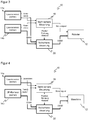
- Figure 3 shows the corresponding security system 10 in a block diagram.
- the safety laser scanners 14a-b monitor an array of detection zones 22 ..22 11 nm.
- the shown regular rectangular grid of mutually identical protective fields 22 11 ..22 nm is particularly clear, but irregular, differently sized and intermittently arranged protective fields are also possible.
- An object 24, here a person, is now detected on the one hand by the safety laser scanners 14a-b in certain protective fields 22 15 , 22 25 and corresponding binary switching signals (OSSD) are transferred to the safety controller 20.
- the scan data are evaluated as non-safe sensor data in the non-safe control 18.
- Distances to the respective scanner center are calculated by means of object localization, as indicated by arrows 26a-b. The distance between the person or the object 24 and the robot 12 can then also be derived from this in accordance with the arrow 28.
- the non-safe control 18 decides on the basis of the distance of the object 24, which can be recognized as a person or only detected as any object, and possibly other variables such as direction and speed of the movement, which control commands should be given to the robot 12 and whether protection is necessary is. This evaluation and control is not yet secure up to this point. They don't Safe controller 18 therefore transfers evaluation results such as position, distance or direction of movement to safety controller 20.
- the safety controller 20 has expectations at least about the position of the object 24 due to the violated protective fields 22 15 , 22 25. This allows an interval to be specified in which the position determined by the non-safe controller 18 or the distance of the object 24 must lie to be plausible. If the evaluation result obtained from the non-safe controller 18 lies within this interval, the calculated distance value is considered plausible. Otherwise, the safety controller 20 itself triggers a safety-related reaction of the robot 12 as soon as it can no longer consider the distance monitoring of the non-safe controller 18 to be reliable.
- Status change means that an object 24 is detected in a previously uninfluenced protective field 22 11 ..22 nm or, conversely, a protective field 22 11 ..22 nm is no longer violated.
- the position of the safety-relevant object 24 is also known particularly precisely in the case of such a status change, since the object 24 then has to be at the protective field boundary. This point in time is therefore particularly favorable for a plausibility check.
- FIG 4 shows a modified further embodiment of the security system 10, in which a secure 3D camera 14b replaces the one security laser scanner 14b.
- the safety laser scanner 14a has a high security level SIL 2 or PL d and the 3D camera 14b has a medium security level PL c.
- the 3D camera might not be safe either.
- the non-safe control 18 has the task of determining the distance between the machine 12 and the object 24 from the non-safe data of the 3D camera 14b, in particular a depth map, and possibly additionally the scan data of the safety laser scanner 14a and possibly process data of the machine 12. The distance is compared in the safety controller 20 with an expected value that is less precisely but very reliably known and is thus upgraded in terms of safety. Further evaluation results, such as the direction of movement or speed, can be determined in the non-safe controller 18 and checked for plausibility in the safety controller 20.
- a grid of protective fields can again be monitored in order to derive the expected value, and in particular the comparison for plausibility checks can be initiated precisely at the time of a signaled protective field status change.
- the high-quality security function of three-dimensional speed-and-separation monitoring can be implemented with a high level of security.
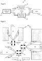
- FIG. 5 shows a schematic block diagram of a further embodiment of the safety system 10 for the safe navigation of a vehicle, specifically an at least partially autonomous vehicle (AGV, Automated Guided Vehicle).
- AGV Automated Guided Vehicle
- An embodiment is shown with only one safety laser scanner 14, it being possible as an alternative to use several safety laser scanners and also other sensors such as cameras and the like.
- the navigation task requires the use of very complex methods such as SLAM (Simultaneous Localization and Mapping), which a safety controller 20 with its limited resources could in no way achieve. Since the non-safe controller 18 in principle uses any hardware, such algorithms can be implemented there.
- SLAM Simultaneous Localization and Mapping
- the safety controller 20 in turn has the task of validating the evaluation results, in particular of confirming positions based on the protective field states of the safety laser scanner 14. To do this, it may send without representation in Figure 5 the non-safe control 18 nor trigger or switching signal for changing protective field configurations to the safety laser scanner 14.
- Test positions can be configured in the working area of the vehicle 12, at which unique environmental features are checked for presence and at least a rough position using special reference protective fields.
- Figure 6 shows, as an application example, the navigation of a vehicle 12a-c in three different positions in a hall with surrounding objects 30, such as shelves, walls and the like.
- a safety laser scanner not shown, at the front of the vehicle 12a-b monitors six simultaneous protective fields S1-S6, which are programmed in such a way that in a reference position, for example at a transfer point, here vehicle 12a, a very specific and as clear as possible combination of the injured and non-injured protective fields S1-S6 or a corresponding OSSD combination of the safety laser scanner is available.
- safe data is transferred from the safety laser scanner to the safety controller 20, which form a six-digit bit pattern corresponding to the six protective fields S1-S6 here as an example and in which an associated bit is set to zero if the protective field is free and to one if it is violated is.
- the safely determined reference position in the safety controller 20 can verify the position of the non-safe controller 18 determined, for example, via SLAM.
- This position confirmation can be completely mapped in the safe test branch of the safety controller 20.
- the safety laser scanner monitors the configured reference protective fields S1-S6 and supplies safe switching signals to the safety controller 20. For trigger points derived from the status of the reference protective fields, the position of which is precisely known, the evaluation result delivered by the non-safe control 18 is matched with the result of the configuration of the reference protective fields known position compared and confirmed.
- the safe data is only a bit pattern of a short length from object detection signals or protective field violations.
- the length here corresponds to the number of simultaneously monitored protective fields and is therefore typically at most ten, at most twenty, at most fifty or at most one hundred.
- the system can offer an automatic mechanism to define or at least suggest protective fields. For example, the vehicle 12a could be brought into the reference position, and the respective protrusion of the protective fields S1, S3, S5 with respect to the protective fields S2, S4, S6 at the border to the surrounding objects 30 is automatically determined.
- the position is preferably validated at positions that are particularly critical in terms of safety, for example where a handover takes place, as in Figure 6 , or where certain safety functions are shut down (muting) or protective fields are switched.
- the trigger can also be generated by the non-safe controller 18 from the determined position data, but then watchdog monitoring is required.
- the status change of one or more reference protective fields can be used as a trigger for a validation. Again, the advantage is that at the moment of the change of state the position of the vehicle 12 is determined particularly precisely even without SLAM.
- a safety laser scanner 14 as in FIG Figures 5 and 6
- Localization and navigation could also be done with other sensors, for example radio-based using UWB (Ultra Wideband).
- UWB Ultra Wideband
- Such a sensor could of course be designed to be safe itself with great effort, but preferably supplements the safety system 10 as an optional non-safe sensor 16 as in FIG Figure 1 .
- the position information is not only generated in a non-secure manner and evaluated in the non-secure control 18, but also transmitted back to the vehicle 12 via a non-secure radio interface.
- the safety controller 20 of the vehicle 12 can then check whether the position that was not reliably determined is correct at the critical point at which the protective fields have to be switched over, for example when entering a truck.
Landscapes
- Engineering & Computer Science (AREA)
- Automation & Control Theory (AREA)
- Physics & Mathematics (AREA)
- General Physics & Mathematics (AREA)
- General Engineering & Computer Science (AREA)
- Mechanical Engineering (AREA)
- Remote Sensing (AREA)
- Radar, Positioning & Navigation (AREA)
- Aviation & Aerospace Engineering (AREA)
- Robotics (AREA)
- Human Computer Interaction (AREA)
- Manufacturing & Machinery (AREA)
- Control Of Position, Course, Altitude, Or Attitude Of Moving Bodies (AREA)
- Traffic Control Systems (AREA)
- Safety Devices In Control Systems (AREA)
Priority Applications (3)
| Application Number | Priority Date | Filing Date | Title |
|---|---|---|---|
| EP19161892.5A EP3709106B1 (fr) | 2019-03-11 | 2019-03-11 | Mise en sécurité d'une machine |
| CN202010102041.7A CN111678026B (zh) | 2019-03-11 | 2020-02-19 | 机器的防护 |
| US16/814,258 US20200290205A1 (en) | 2019-03-11 | 2020-03-10 | Safeguarding a machine |
Applications Claiming Priority (1)
| Application Number | Priority Date | Filing Date | Title |
|---|---|---|---|
| EP19161892.5A EP3709106B1 (fr) | 2019-03-11 | 2019-03-11 | Mise en sécurité d'une machine |
Publications (2)
| Publication Number | Publication Date |
|---|---|
| EP3709106A1 true EP3709106A1 (fr) | 2020-09-16 |
| EP3709106B1 EP3709106B1 (fr) | 2021-01-06 |
Family
ID=65763349
Family Applications (1)
| Application Number | Title | Priority Date | Filing Date |
|---|---|---|---|
| EP19161892.5A Active EP3709106B1 (fr) | 2019-03-11 | 2019-03-11 | Mise en sécurité d'une machine |
Country Status (3)
| Country | Link |
|---|---|
| US (1) | US20200290205A1 (fr) |
| EP (1) | EP3709106B1 (fr) |
| CN (1) | CN111678026B (fr) |
Cited By (14)
| Publication number | Priority date | Publication date | Assignee | Title |
|---|---|---|---|---|
| DE102022100797A1 (de) | 2021-02-04 | 2022-08-04 | Sick Ag | Sicherheitsvorrichtung und Sicherheitsverfahren zur Überwachung einer Maschine |
| EP4070920A1 (fr) * | 2021-04-08 | 2022-10-12 | Siemens Aktiengesellschaft | Système de robot mobile autonome et procédé de fonctionnement |
| EP4130898A1 (fr) * | 2021-08-04 | 2023-02-08 | Sick Ag | Système de sécurité et procédé doté d'un système de sécurité |
| WO2023077459A1 (fr) * | 2021-11-05 | 2023-05-11 | 美的集团股份有限公司 | Système de commande de sécurité et dispositif de commande de sécurité pour robot industriel |
| EP4307249A1 (fr) * | 2022-07-13 | 2024-01-17 | Siemens Aktiengesellschaft | Système de surveillance doté d'un détecteur de personnes |
| DE102022120850A1 (de) * | 2022-08-18 | 2024-02-29 | Sick Ag | Sicherheitssystem und Verfahren mit einem Sicherheitssystem |
| EP4390577A1 (fr) | 2022-12-22 | 2024-06-26 | Sick Ag | Surveillance d'au moins une machine |
| EP4431985A1 (fr) | 2023-03-15 | 2024-09-18 | Sick Ag | Suivi d'objet sécurisé d'un objet |
| EP4451070A1 (fr) * | 2023-04-20 | 2024-10-23 | Siemens Aktiengesellschaft | Système de surveillance et procédé de son fonctionnement |
| EP4478138A1 (fr) * | 2023-06-15 | 2024-12-18 | Sick Ag | Système de sécurité pour une machine |
| EP4516463A1 (fr) | 2023-08-29 | 2025-03-05 | Sick Ag | Protection sans contact sur une zone de coopération d'une machine |
| EP4650886A1 (fr) | 2024-05-17 | 2025-11-19 | Sick Ag | Dispositifs et procédés de sécurité |
| EP4650644A1 (fr) | 2024-05-17 | 2025-11-19 | Sick Ag | Dispositifs et procédés de sécurité |
| EP4660513A1 (fr) | 2024-06-05 | 2025-12-10 | Sick Ag | Système de sécurité et procédé de sécurisation d'une machine |
Families Citing this family (12)
| Publication number | Priority date | Publication date | Assignee | Title |
|---|---|---|---|---|
| US20220234209A1 (en) * | 2019-08-23 | 2022-07-28 | Ilya A. Kriveshko | Safe operation of machinery using potential occupancy envelopes |
| US11921484B1 (en) * | 2020-07-21 | 2024-03-05 | Amazon Technologies, Inc. | Safety rated robotic motor control |
| DE102020120301A1 (de) * | 2020-07-31 | 2022-02-03 | Bayerische Motoren Werke Aktiengesellschaft | Fahrassistenzsystem und Fahrassistenzverfahren für ein Fahrzeug |
| DE102021101180A1 (de) * | 2021-01-21 | 2022-07-21 | Sick Ag | Sicherheitssystem |
| US12157234B2 (en) * | 2021-06-21 | 2024-12-03 | Intrinsic Innovation Llc | Safety trajectories for robotic control systems |
| US12154185B2 (en) | 2021-12-22 | 2024-11-26 | Datalogic Ip Tech S.R.L. | System and method for verifying positional and spatial information using depth sensors |
| DE102022100840A1 (de) * | 2022-01-14 | 2023-07-20 | Sick Ag | Augmented-reality-system zum unterrichten eines anwenders einer applikation |
| EP4286973A1 (fr) * | 2022-06-02 | 2023-12-06 | Siemens Aktiengesellschaft | Procédé, produit programme logiciel et dispositif de surveillance axée sur la sécurité de la vitesse d'une unité de mouvement autonome |
| DE102022130166B4 (de) * | 2022-11-15 | 2025-03-27 | Sick Ag | Sicherheitssystem und Verfahren mit einem Sicherheitssystem |
| CN116834962B (zh) * | 2023-01-09 | 2024-10-01 | 申炳龙 | 一种无人无牵引杆的飞机牵引控制系统及智能牵引车 |
| EP4481260A1 (fr) * | 2023-06-22 | 2024-12-25 | Leuze electronic GmbH + Co. KG | Dispositif de surveillance et procédé de fonctionnement d'un dispositif de surveillance |
| DE202024106666U1 (de) * | 2024-11-19 | 2026-04-02 | Leuze Electronic Gmbh + Co. Kg | Überwachungseinrichtung |
Citations (6)
| Publication number | Priority date | Publication date | Assignee | Title |
|---|---|---|---|---|
| DE4340756A1 (de) | 1992-12-08 | 1994-06-09 | Sick Optik Elektronik Erwin | Laserabstandsermittlungsvorrichtung |
| DE102006048146A1 (de) * | 2006-10-10 | 2008-04-17 | Sick Ag | Sensoranordnung zur Sicherheitsüberwachung einer Maschine |
| WO2010094466A1 (fr) | 2009-02-23 | 2010-08-26 | Pilz Gmbh & Co. Kg | Procédé et dispositif pour réaliser un programme d'application pour une commande de sécurité |
| DE102010007520B3 (de) * | 2010-02-11 | 2011-05-05 | Sick Ag | Sicherheitssteuerung mit einer Vielzahl von Anschlüssen für Sensoren |
| EP2395372A1 (fr) | 2010-06-09 | 2011-12-14 | Sick AG | Scanner de sécurité |
| EP2825812A1 (fr) | 2012-03-16 | 2015-01-21 | Pilz GmbH & Co. KG | Procédé et dispositif destinés sécuriser une zone de travail dangereuse d'une machine à fonctionnement automatique. |
Family Cites Families (14)
| Publication number | Priority date | Publication date | Assignee | Title |
|---|---|---|---|---|
| DE102004031678A1 (de) * | 2004-06-30 | 2006-01-26 | Sick Ag | Sicherungsverfahren und Sicherungsvorrichtung |
| EP1901150B1 (fr) * | 2006-09-14 | 2008-10-29 | Abb Research Ltd. | Procédé et dispositif permettant d'éviter les collisions entre un robot industriel et un objet |
| EP2053538B1 (fr) * | 2007-10-25 | 2014-02-26 | Sick Ag | Protection d'une zone de surveillance et support visuel d'un usinage automatisé |
| EP2083209B1 (fr) * | 2008-01-28 | 2012-10-17 | Sick Ag | Système de sécurité destiné à la mesure sans contact de voies et/ou de vitesses |
| KR101651440B1 (ko) * | 2008-05-16 | 2016-08-26 | 코닌클리케 필립스 엔.브이. | 셀프-믹싱 레이저 센서를 포함하는 방어 시스템 및 그러한 방어 시스템을 구동하는 방법 |
| US9079305B2 (en) * | 2012-08-28 | 2015-07-14 | Rethink Robotics, Inc. | Monitoring robot sensor consistency |
| DE102013104265A1 (de) * | 2013-04-26 | 2014-10-30 | Pilz Gmbh & Co. Kg | Vorrichtung und Verfahren zum Absichern einer automatisiert arbeitenden Maschine |
| DE102013106514B3 (de) * | 2013-06-21 | 2014-10-30 | Pilz Gmbh & Co. Kg | Vorrichtung und Verfahren zum Absichern einer automatisiert arbeitenden Maschine |
| US9256944B2 (en) * | 2014-05-19 | 2016-02-09 | Rockwell Automation Technologies, Inc. | Integration of optical area monitoring with industrial machine control |
| US9927797B2 (en) * | 2014-08-29 | 2018-03-27 | Amazon Technologies, Inc. | Safety compliance for mobile drive units |
| DE102017202004A1 (de) * | 2017-02-08 | 2018-08-09 | Thyssenkrupp Ag | Vorrichtung zur Absicherung eines maschinell gesteuerten Handhabungsgeräts und Verfahren |
| DE102017105174B4 (de) * | 2017-03-10 | 2020-04-23 | Sick Ag | Verfahren zum Erzeugen von Trainingsdaten für die Überwachung einer Gefahrenquelle |
| DE102017112419B3 (de) * | 2017-06-06 | 2018-09-06 | Sick Ag | Zugangsabsicherungssystem |
| EP3421189B1 (fr) * | 2017-06-28 | 2019-05-22 | Sick AG | Procédé de surveillance d'une machine |
-
2019
- 2019-03-11 EP EP19161892.5A patent/EP3709106B1/fr active Active
-
2020
- 2020-02-19 CN CN202010102041.7A patent/CN111678026B/zh active Active
- 2020-03-10 US US16/814,258 patent/US20200290205A1/en not_active Abandoned
Patent Citations (6)
| Publication number | Priority date | Publication date | Assignee | Title |
|---|---|---|---|---|
| DE4340756A1 (de) | 1992-12-08 | 1994-06-09 | Sick Optik Elektronik Erwin | Laserabstandsermittlungsvorrichtung |
| DE102006048146A1 (de) * | 2006-10-10 | 2008-04-17 | Sick Ag | Sensoranordnung zur Sicherheitsüberwachung einer Maschine |
| WO2010094466A1 (fr) | 2009-02-23 | 2010-08-26 | Pilz Gmbh & Co. Kg | Procédé et dispositif pour réaliser un programme d'application pour une commande de sécurité |
| DE102010007520B3 (de) * | 2010-02-11 | 2011-05-05 | Sick Ag | Sicherheitssteuerung mit einer Vielzahl von Anschlüssen für Sensoren |
| EP2395372A1 (fr) | 2010-06-09 | 2011-12-14 | Sick AG | Scanner de sécurité |
| EP2825812A1 (fr) | 2012-03-16 | 2015-01-21 | Pilz GmbH & Co. KG | Procédé et dispositif destinés sécuriser une zone de travail dangereuse d'une machine à fonctionnement automatique. |
Non-Patent Citations (1)
| Title |
|---|
| N N: "User's Manual Safety Laser Scanner OS32C Series", 1 January 2015 (2015-01-01), pages i-xx,1 - 157, XP055616257, Retrieved from the Internet <URL:https://assets.omron.eu/downloads/manual/en/v1/z296_os32c_users_manual_en.pdf> [retrieved on 20190828] * |
Cited By (20)
| Publication number | Priority date | Publication date | Assignee | Title |
|---|---|---|---|---|
| US12260252B2 (en) | 2021-02-04 | 2025-03-25 | Sick Ag | Safety device and safety method for monitoring a machine |
| EP4040034A1 (fr) | 2021-02-04 | 2022-08-10 | Sick Ag | Dispositif de sécurité et procédés de sécurité destiné à la surveillance d'une machine |
| DE102022100797A1 (de) | 2021-02-04 | 2022-08-04 | Sick Ag | Sicherheitsvorrichtung und Sicherheitsverfahren zur Überwachung einer Maschine |
| EP4070920A1 (fr) * | 2021-04-08 | 2022-10-12 | Siemens Aktiengesellschaft | Système de robot mobile autonome et procédé de fonctionnement |
| EP4130898A1 (fr) * | 2021-08-04 | 2023-02-08 | Sick Ag | Système de sécurité et procédé doté d'un système de sécurité |
| WO2023077459A1 (fr) * | 2021-11-05 | 2023-05-11 | 美的集团股份有限公司 | Système de commande de sécurité et dispositif de commande de sécurité pour robot industriel |
| EP4307249A1 (fr) * | 2022-07-13 | 2024-01-17 | Siemens Aktiengesellschaft | Système de surveillance doté d'un détecteur de personnes |
| WO2024012746A1 (fr) | 2022-07-13 | 2024-01-18 | Siemens Aktiengesellschaft | Système de surveillance comprenant un détecteur de personne |
| DE102022120850A1 (de) * | 2022-08-18 | 2024-02-29 | Sick Ag | Sicherheitssystem und Verfahren mit einem Sicherheitssystem |
| EP4390577A1 (fr) | 2022-12-22 | 2024-06-26 | Sick Ag | Surveillance d'au moins une machine |
| EP4431985A1 (fr) | 2023-03-15 | 2024-09-18 | Sick Ag | Suivi d'objet sécurisé d'un objet |
| EP4451070A1 (fr) * | 2023-04-20 | 2024-10-23 | Siemens Aktiengesellschaft | Système de surveillance et procédé de son fonctionnement |
| US12589497B2 (en) | 2023-04-20 | 2026-03-31 | Siemens Aktiengesellschaft | Monitoring system and method for operating the system |
| EP4478138A1 (fr) * | 2023-06-15 | 2024-12-18 | Sick Ag | Système de sécurité pour une machine |
| EP4516463A1 (fr) | 2023-08-29 | 2025-03-05 | Sick Ag | Protection sans contact sur une zone de coopération d'une machine |
| JP2025036161A (ja) * | 2023-08-29 | 2025-03-14 | ジック アーゲー | 機械の共同作業領域における非接触防護 |
| JP7767523B2 (ja) | 2023-08-29 | 2025-11-11 | ジック アーゲー | 機械の共同作業領域における非接触防護 |
| EP4650886A1 (fr) | 2024-05-17 | 2025-11-19 | Sick Ag | Dispositifs et procédés de sécurité |
| EP4650644A1 (fr) | 2024-05-17 | 2025-11-19 | Sick Ag | Dispositifs et procédés de sécurité |
| EP4660513A1 (fr) | 2024-06-05 | 2025-12-10 | Sick Ag | Système de sécurité et procédé de sécurisation d'une machine |
Also Published As
| Publication number | Publication date |
|---|---|
| CN111678026B (zh) | 2023-05-16 |
| US20200290205A1 (en) | 2020-09-17 |
| CN111678026A (zh) | 2020-09-18 |
| EP3709106B1 (fr) | 2021-01-06 |
Similar Documents
| Publication | Publication Date | Title |
|---|---|---|
| EP3709106B1 (fr) | Mise en sécurité d'une machine | |
| EP3578319B1 (fr) | Procédé de sécurisation d'un endroit dangereux | |
| EP3611422B1 (fr) | Dispositif capteur et procédé de sécurisation d'une zone de surveillance | |
| EP4040034B1 (fr) | Dispositif de sécurité et procédés de sécurité destiné à la surveillance d'une machine | |
| EP3455153B1 (fr) | Procédé et système pour éviter des collisions par des grues | |
| DE102019110882B4 (de) | Absichern eines beweglichen Maschinenteils | |
| EP3650740B1 (fr) | Système de sécurité et procédé de surveillance d'une machine | |
| EP3744482A1 (fr) | Fixation d'une pièce de machine mobile | |
| DE102010007520B3 (de) | Sicherheitssteuerung mit einer Vielzahl von Anschlüssen für Sensoren | |
| EP4124789B1 (fr) | Fixation d'une pièce de machine mobile | |
| EP3988256B1 (fr) | Fixation d'une pièce de machine mobile | |
| DE102019211770B3 (de) | Verfahren zur rechnergestützten Erfassung und Auswertung eines Arbeitsablaufs, bei dem ein menschlicher Werker und ein robotisches System wechselwirken | |
| DE102017111885B4 (de) | Verfahren und System zum Überwachen einer Maschine | |
| EP4414143A1 (fr) | Procédé et capteur de distance sans contact pour sécuriser une machine | |
| EP3916286A1 (fr) | Capteur optoélectronique de sécurité et procédé de sécurisation d'une machine | |
| EP4385676B1 (fr) | Validation de la pose d'un robot et des données d'un capteur se déplaçant avec le robot | |
| DE102020129823B4 (de) | Visualisieren eines Schutzfeldes | |
| DE202020106491U1 (de) | Visualisieren eines Schutzfeldes | |
| EP4008497A1 (fr) | Validation d'une pose d'un robot | |
| EP4303684A1 (fr) | Système de sécurité redondant et procédé avec un système de sécurité redondant | |
| EP3825731B1 (fr) | Capteur optoélectronique de sécurité et procédé de détermination sécurisée de position propre | |
| EP4390577B1 (fr) | Surveillance d'au moins une machine | |
| EP4478138B1 (fr) | Système de sécurité pour une machine et procédé correspondant | |
| EP4660513B1 (fr) | Système de sécurité et procédé de sécurisation d'une machine | |
| EP4431985B1 (fr) | Suivi d'objet sécurisé d'un objet |
Legal Events
| Date | Code | Title | Description |
|---|---|---|---|
| STAA | Information on the status of an ep patent application or granted ep patent |
Free format text: STATUS: EXAMINATION IS IN PROGRESS |
|
| PUAI | Public reference made under article 153(3) epc to a published international application that has entered the european phase |
Free format text: ORIGINAL CODE: 0009012 |
|
| 17P | Request for examination filed |
Effective date: 20191206 |
|
| AK | Designated contracting states |
Kind code of ref document: A1 Designated state(s): AL AT BE BG CH CY CZ DE DK EE ES FI FR GB GR HR HU IE IS IT LI LT LU LV MC MK MT NL NO PL PT RO RS SE SI SK SM TR |
|
| AX | Request for extension of the european patent |
Extension state: BA ME |
|
| GRAP | Despatch of communication of intention to grant a patent |
Free format text: ORIGINAL CODE: EPIDOSNIGR1 |
|
| STAA | Information on the status of an ep patent application or granted ep patent |
Free format text: STATUS: GRANT OF PATENT IS INTENDED |
|
| INTG | Intention to grant announced |
Effective date: 20201021 |
|
| GRAS | Grant fee paid |
Free format text: ORIGINAL CODE: EPIDOSNIGR3 |
|
| GRAA | (expected) grant |
Free format text: ORIGINAL CODE: 0009210 |
|
| STAA | Information on the status of an ep patent application or granted ep patent |
Free format text: STATUS: THE PATENT HAS BEEN GRANTED |
|
| AK | Designated contracting states |
Kind code of ref document: B1 Designated state(s): AL AT BE BG CH CY CZ DE DK EE ES FI FR GB GR HR HU IE IS IT LI LT LU LV MC MK MT NL NO PL PT RO RS SE SI SK SM TR |
|
| REG | Reference to a national code |
Ref country code: GB Ref legal event code: FG4D Free format text: NOT ENGLISH |
|
| REG | Reference to a national code |
Ref country code: AT Ref legal event code: REF Ref document number: 1353035 Country of ref document: AT Kind code of ref document: T Effective date: 20210115 Ref country code: CH Ref legal event code: EP |
|
| REG | Reference to a national code |
Ref country code: DE Ref legal event code: R096 Ref document number: 502019000629 Country of ref document: DE |
|
| REG | Reference to a national code |
Ref country code: IE Ref legal event code: FG4D Free format text: LANGUAGE OF EP DOCUMENT: GERMAN |
|
| REG | Reference to a national code |
Ref country code: NL Ref legal event code: MP Effective date: 20210106 |
|
| REG | Reference to a national code |
Ref country code: LT Ref legal event code: MG9D |
|
| PG25 | Lapsed in a contracting state [announced via postgrant information from national office to epo] |
Ref country code: LT Free format text: LAPSE BECAUSE OF FAILURE TO SUBMIT A TRANSLATION OF THE DESCRIPTION OR TO PAY THE FEE WITHIN THE PRESCRIBED TIME-LIMIT Effective date: 20210106 Ref country code: NO Free format text: LAPSE BECAUSE OF FAILURE TO SUBMIT A TRANSLATION OF THE DESCRIPTION OR TO PAY THE FEE WITHIN THE PRESCRIBED TIME-LIMIT Effective date: 20210406 Ref country code: PT Free format text: LAPSE BECAUSE OF FAILURE TO SUBMIT A TRANSLATION OF THE DESCRIPTION OR TO PAY THE FEE WITHIN THE PRESCRIBED TIME-LIMIT Effective date: 20210506 Ref country code: HR Free format text: LAPSE BECAUSE OF FAILURE TO SUBMIT A TRANSLATION OF THE DESCRIPTION OR TO PAY THE FEE WITHIN THE PRESCRIBED TIME-LIMIT Effective date: 20210106 Ref country code: GR Free format text: LAPSE BECAUSE OF FAILURE TO SUBMIT A TRANSLATION OF THE DESCRIPTION OR TO PAY THE FEE WITHIN THE PRESCRIBED TIME-LIMIT Effective date: 20210407 Ref country code: FI Free format text: LAPSE BECAUSE OF FAILURE TO SUBMIT A TRANSLATION OF THE DESCRIPTION OR TO PAY THE FEE WITHIN THE PRESCRIBED TIME-LIMIT Effective date: 20210106 Ref country code: BG Free format text: LAPSE BECAUSE OF FAILURE TO SUBMIT A TRANSLATION OF THE DESCRIPTION OR TO PAY THE FEE WITHIN THE PRESCRIBED TIME-LIMIT Effective date: 20210406 |
|
| PG25 | Lapsed in a contracting state [announced via postgrant information from national office to epo] |
Ref country code: SE Free format text: LAPSE BECAUSE OF FAILURE TO SUBMIT A TRANSLATION OF THE DESCRIPTION OR TO PAY THE FEE WITHIN THE PRESCRIBED TIME-LIMIT Effective date: 20210106 Ref country code: PL Free format text: LAPSE BECAUSE OF FAILURE TO SUBMIT A TRANSLATION OF THE DESCRIPTION OR TO PAY THE FEE WITHIN THE PRESCRIBED TIME-LIMIT Effective date: 20210106 Ref country code: RS Free format text: LAPSE BECAUSE OF FAILURE TO SUBMIT A TRANSLATION OF THE DESCRIPTION OR TO PAY THE FEE WITHIN THE PRESCRIBED TIME-LIMIT Effective date: 20210106 Ref country code: LV Free format text: LAPSE BECAUSE OF FAILURE TO SUBMIT A TRANSLATION OF THE DESCRIPTION OR TO PAY THE FEE WITHIN THE PRESCRIBED TIME-LIMIT Effective date: 20210106 |
|
| PG25 | Lapsed in a contracting state [announced via postgrant information from national office to epo] |
Ref country code: IS Free format text: LAPSE BECAUSE OF FAILURE TO SUBMIT A TRANSLATION OF THE DESCRIPTION OR TO PAY THE FEE WITHIN THE PRESCRIBED TIME-LIMIT Effective date: 20210506 |
|
| REG | Reference to a national code |
Ref country code: DE Ref legal event code: R097 Ref document number: 502019000629 Country of ref document: DE |
|
| PG25 | Lapsed in a contracting state [announced via postgrant information from national office to epo] |
Ref country code: MC Free format text: LAPSE BECAUSE OF FAILURE TO SUBMIT A TRANSLATION OF THE DESCRIPTION OR TO PAY THE FEE WITHIN THE PRESCRIBED TIME-LIMIT Effective date: 20210106 Ref country code: EE Free format text: LAPSE BECAUSE OF FAILURE TO SUBMIT A TRANSLATION OF THE DESCRIPTION OR TO PAY THE FEE WITHIN THE PRESCRIBED TIME-LIMIT Effective date: 20210106 Ref country code: CZ Free format text: LAPSE BECAUSE OF FAILURE TO SUBMIT A TRANSLATION OF THE DESCRIPTION OR TO PAY THE FEE WITHIN THE PRESCRIBED TIME-LIMIT Effective date: 20210106 Ref country code: SM Free format text: LAPSE BECAUSE OF FAILURE TO SUBMIT A TRANSLATION OF THE DESCRIPTION OR TO PAY THE FEE WITHIN THE PRESCRIBED TIME-LIMIT Effective date: 20210106 |
|
| PLBE | No opposition filed within time limit |
Free format text: ORIGINAL CODE: 0009261 |
|
| STAA | Information on the status of an ep patent application or granted ep patent |
Free format text: STATUS: NO OPPOSITION FILED WITHIN TIME LIMIT |
|
| PG25 | Lapsed in a contracting state [announced via postgrant information from national office to epo] |
Ref country code: DK Free format text: LAPSE BECAUSE OF FAILURE TO SUBMIT A TRANSLATION OF THE DESCRIPTION OR TO PAY THE FEE WITHIN THE PRESCRIBED TIME-LIMIT Effective date: 20210106 Ref country code: SK Free format text: LAPSE BECAUSE OF FAILURE TO SUBMIT A TRANSLATION OF THE DESCRIPTION OR TO PAY THE FEE WITHIN THE PRESCRIBED TIME-LIMIT Effective date: 20210106 Ref country code: RO Free format text: LAPSE BECAUSE OF FAILURE TO SUBMIT A TRANSLATION OF THE DESCRIPTION OR TO PAY THE FEE WITHIN THE PRESCRIBED TIME-LIMIT Effective date: 20210106 |
|
| 26N | No opposition filed |
Effective date: 20211007 |
|
| REG | Reference to a national code |
Ref country code: BE Ref legal event code: MM Effective date: 20210331 |
|
| PG25 | Lapsed in a contracting state [announced via postgrant information from national office to epo] |
Ref country code: IE Free format text: LAPSE BECAUSE OF NON-PAYMENT OF DUE FEES Effective date: 20210311 Ref country code: LU Free format text: LAPSE BECAUSE OF NON-PAYMENT OF DUE FEES Effective date: 20210311 Ref country code: AL Free format text: LAPSE BECAUSE OF FAILURE TO SUBMIT A TRANSLATION OF THE DESCRIPTION OR TO PAY THE FEE WITHIN THE PRESCRIBED TIME-LIMIT Effective date: 20210106 Ref country code: ES Free format text: LAPSE BECAUSE OF FAILURE TO SUBMIT A TRANSLATION OF THE DESCRIPTION OR TO PAY THE FEE WITHIN THE PRESCRIBED TIME-LIMIT Effective date: 20210106 |
|
| PG25 | Lapsed in a contracting state [announced via postgrant information from national office to epo] |
Ref country code: IT Free format text: LAPSE BECAUSE OF FAILURE TO SUBMIT A TRANSLATION OF THE DESCRIPTION OR TO PAY THE FEE WITHIN THE PRESCRIBED TIME-LIMIT Effective date: 20210106 |
|
| PG25 | Lapsed in a contracting state [announced via postgrant information from national office to epo] |
Ref country code: IS Free format text: LAPSE BECAUSE OF FAILURE TO SUBMIT A TRANSLATION OF THE DESCRIPTION OR TO PAY THE FEE WITHIN THE PRESCRIBED TIME-LIMIT Effective date: 20210506 |
|
| PG25 | Lapsed in a contracting state [announced via postgrant information from national office to epo] |
Ref country code: BE Free format text: LAPSE BECAUSE OF NON-PAYMENT OF DUE FEES Effective date: 20210331 |
|
| PG25 | Lapsed in a contracting state [announced via postgrant information from national office to epo] |
Ref country code: NL Free format text: LAPSE BECAUSE OF NON-PAYMENT OF DUE FEES Effective date: 20210206 Ref country code: CY Free format text: LAPSE BECAUSE OF FAILURE TO SUBMIT A TRANSLATION OF THE DESCRIPTION OR TO PAY THE FEE WITHIN THE PRESCRIBED TIME-LIMIT Effective date: 20210106 |
|
| PG25 | Lapsed in a contracting state [announced via postgrant information from national office to epo] |
Ref country code: SI Free format text: LAPSE BECAUSE OF FAILURE TO SUBMIT A TRANSLATION OF THE DESCRIPTION OR TO PAY THE FEE WITHIN THE PRESCRIBED TIME-LIMIT Effective date: 20210106 Ref country code: HU Free format text: LAPSE BECAUSE OF FAILURE TO SUBMIT A TRANSLATION OF THE DESCRIPTION OR TO PAY THE FEE WITHIN THE PRESCRIBED TIME-LIMIT; INVALID AB INITIO Effective date: 20190311 |
|
| PG25 | Lapsed in a contracting state [announced via postgrant information from national office to epo] |
Ref country code: MK Free format text: LAPSE BECAUSE OF FAILURE TO SUBMIT A TRANSLATION OF THE DESCRIPTION OR TO PAY THE FEE WITHIN THE PRESCRIBED TIME-LIMIT Effective date: 20210106 |
|
| PG25 | Lapsed in a contracting state [announced via postgrant information from national office to epo] |
Ref country code: MT Free format text: LAPSE BECAUSE OF FAILURE TO SUBMIT A TRANSLATION OF THE DESCRIPTION OR TO PAY THE FEE WITHIN THE PRESCRIBED TIME-LIMIT Effective date: 20210106 |
|
| REG | Reference to a national code |
Ref country code: AT Ref legal event code: MM01 Ref document number: 1353035 Country of ref document: AT Kind code of ref document: T Effective date: 20240311 |
|
| PGFP | Annual fee paid to national office [announced via postgrant information from national office to epo] |
Ref country code: CH Payment date: 20250401 Year of fee payment: 7 |
|
| PG25 | Lapsed in a contracting state [announced via postgrant information from national office to epo] |
Ref country code: AT Free format text: LAPSE BECAUSE OF NON-PAYMENT OF DUE FEES Effective date: 20240311 |
|
| PG25 | Lapsed in a contracting state [announced via postgrant information from national office to epo] |
Ref country code: TR Free format text: LAPSE BECAUSE OF FAILURE TO SUBMIT A TRANSLATION OF THE DESCRIPTION OR TO PAY THE FEE WITHIN THE PRESCRIBED TIME-LIMIT Effective date: 20210106 |
|
| REG | Reference to a national code |
Ref country code: CH Ref legal event code: U11 Free format text: ST27 STATUS EVENT CODE: U-0-0-U10-U11 (AS PROVIDED BY THE NATIONAL OFFICE) Effective date: 20260401 |
|
| PGFP | Annual fee paid to national office [announced via postgrant information from national office to epo] |
Ref country code: GB Payment date: 20260324 Year of fee payment: 8 |
|
| PGFP | Annual fee paid to national office [announced via postgrant information from national office to epo] |
Ref country code: DE Payment date: 20260320 Year of fee payment: 8 |
|
| PGFP | Annual fee paid to national office [announced via postgrant information from national office to epo] |
Ref country code: AT Payment date: 20260410 Year of fee payment: 5 |
|
| PGFP | Annual fee paid to national office [announced via postgrant information from national office to epo] |
Ref country code: FR Payment date: 20260325 Year of fee payment: 8 |