EP3712334A1 - Engin de chantier - Google Patents
Engin de chantier Download PDFInfo
- Publication number
- EP3712334A1 EP3712334A1 EP19826987.0A EP19826987A EP3712334A1 EP 3712334 A1 EP3712334 A1 EP 3712334A1 EP 19826987 A EP19826987 A EP 19826987A EP 3712334 A1 EP3712334 A1 EP 3712334A1
- Authority
- EP
- European Patent Office
- Prior art keywords
- bucket
- boom
- arm
- work machine
- vehicle body
- Prior art date
- Legal status (The legal status is an assumption and is not a legal conclusion. Google has not performed a legal analysis and makes no representation as to the accuracy of the status listed.)
- Withdrawn
Links
Images




Classifications
-
- E—FIXED CONSTRUCTIONS
- E02—HYDRAULIC ENGINEERING; FOUNDATIONS; SOIL SHIFTING
- E02F—DREDGING; SOIL-SHIFTING
- E02F3/00—Dredgers; Soil-shifting machines
- E02F3/04—Dredgers; Soil-shifting machines mechanically-driven
- E02F3/28—Dredgers; Soil-shifting machines mechanically-driven with digging tools mounted on a dipper- or bucket-arm, i.e. there is either one arm or a pair of arms, e.g. dippers, buckets
- E02F3/34—Dredgers; Soil-shifting machines mechanically-driven with digging tools mounted on a dipper- or bucket-arm, i.e. there is either one arm or a pair of arms, e.g. dippers, buckets with bucket-arms, i.e. a pair of arms, e.g. manufacturing processes, form, geometry, material of bucket-arms directly pivoted on the frames of tractors or self-propelled machines
- E02F3/3405—Dredgers; Soil-shifting machines mechanically-driven with digging tools mounted on a dipper- or bucket-arm, i.e. there is either one arm or a pair of arms, e.g. dippers, buckets with bucket-arms, i.e. a pair of arms, e.g. manufacturing processes, form, geometry, material of bucket-arms directly pivoted on the frames of tractors or self-propelled machines and comprising an additional linkage mechanism
- E02F3/3408—Dredgers; Soil-shifting machines mechanically-driven with digging tools mounted on a dipper- or bucket-arm, i.e. there is either one arm or a pair of arms, e.g. dippers, buckets with bucket-arms, i.e. a pair of arms, e.g. manufacturing processes, form, geometry, material of bucket-arms directly pivoted on the frames of tractors or self-propelled machines and comprising an additional linkage mechanism of the parallelogram-type
-
- E—FIXED CONSTRUCTIONS
- E02—HYDRAULIC ENGINEERING; FOUNDATIONS; SOIL SHIFTING
- E02F—DREDGING; SOIL-SHIFTING
- E02F3/00—Dredgers; Soil-shifting machines
- E02F3/04—Dredgers; Soil-shifting machines mechanically-driven
- E02F3/28—Dredgers; Soil-shifting machines mechanically-driven with digging tools mounted on a dipper- or bucket-arm, i.e. there is either one arm or a pair of arms, e.g. dippers, buckets
- E02F3/30—Dredgers; Soil-shifting machines mechanically-driven with digging tools mounted on a dipper- or bucket-arm, i.e. there is either one arm or a pair of arms, e.g. dippers, buckets with a dipper-arm pivoted on a cantilever beam, i.e. boom
- E02F3/308—Dredgers; Soil-shifting machines mechanically-driven with digging tools mounted on a dipper- or bucket-arm, i.e. there is either one arm or a pair of arms, e.g. dippers, buckets with a dipper-arm pivoted on a cantilever beam, i.e. boom working outwardly
-
- E—FIXED CONSTRUCTIONS
- E02—HYDRAULIC ENGINEERING; FOUNDATIONS; SOIL SHIFTING
- E02F—DREDGING; SOIL-SHIFTING
- E02F9/00—Component parts of dredgers or soil-shifting machines, not restricted to one of the kinds covered by groups E02F3/00 - E02F7/00
- E02F9/08—Superstructures; Supports for superstructures
- E02F9/0841—Articulated frame, i.e. having at least one pivot point between two travelling gear units
Definitions
- the present invention relates to a work machine.
- a wheel loader is known as one of work machines.
- the wheel loader includes a boom and a bucket.
- the wheel loader excavates an excavation target with a bucket, and loads an excavated object on the bed of a transport vehicle.
- Patent Literature 1 JP 2007-186929 A
- a wheel loader When excavating an excavation target with a bucket, a wheel loader moves forward toward the excavation target with the bucket close to the ground, and inserts the bucket near a boundary between the ground and the excavation target.
- the wheel loader When loading an excavated object scooped by the bucket onto the bed of a transport vehicle, the wheel loader moves backward to be separated from the excavation target and, then, raises the boom while moving forward toward the transport vehicle. After positioning the bucket at a position higher than the bed by raising the boom, the wheel loader causes the bucket to perform a dumping operation to discharge the excavated object from the bucket to the bed.
- the bucket is positioned at a low position near the ground in excavation work for excavating an excavation target, and the bucket is positioned at a position higher than the bed in loading work for loading an excavated object on the bed.
- the wheel loader needs to greatly move the bucket in the vertical direction between the excavation work and the loading work. If the bucket needs to be greatly moved in the vertical direction, this requires a large power, and the fuel consumption of the wheel loader can increase. In addition, if the bucket needs to be greatly moved in the vertical direction while the wheel loader is moving forward or backward, the moving distance and the moving time of the bucket become longer, and the working time of the wheel loader becomes longer.
- An aspect of the present invention is to reduce fuel consumption and to shorten working time.
- a work machine comprises: a vehicle body supported by wheels; a boom drivable with respect to the vehicle body; an arm drivable with respect to the boom; a bucket including an opening and drivable with respect to the arm in a manner such that the opening faces forward; a boom actuator configured to drive the boom; an arm actuator configured to drive the arm; and a bucket actuator configured to drive the bucket.
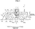
- FIG. 1 is a side view schematically illustrating a work machine 1 according to an embodiment.
- FIG. 2 is a plan view schematically illustrating the work machine 1 according to the embodiment.
- the work machine 1 is a wheel loader. The work machine 1 loads an excavated object scooped by a bucket 13 on the bed of a transport vehicle.
- the work machine 1 includes a vehicle body 2 supported by wheels 4, a traveling device 3 that supports the vehicle body 2 and travels, and a working equipment 10 supported by the vehicle body 2.
- the vehicle body 2 includes a front vehicle body 2F, a rear vehicle body 2R, and a joint mechanism 9 that couples the front vehicle body 2F and the rear vehicle body 2R so as to be bendable.
- the rear vehicle body 2R is provided with a cab 6.
- the cab 6 is provided with an operation seat 7 and an operation device 8.
- the operator of the work machine 1 operates the operation device 8 while sitting on the operation seat 7. Note that, one or both of the operation seat 7 and the operation device 8 may not be provided in the cab 6.
- the traveling device 3 supports the vehicle body 2.
- the traveling device 3 includes the joint mechanism 9 and the wheels 4.
- the joint mechanism 9 includes a steering cylinder. One end of the joint mechanism 9 is coupled to the front vehicle body 2F, and the other end of the joint mechanism 9 is coupled to the rear vehicle body 2R.
- the steering cylinder extends and retracts, and the vehicle body 2 thereby bends.
- the vehicle body 2 bends, and the work machine 1 thereby swings.
- the wheels 4 are rotated by power generated by an engine (not illustrated) mounted on the vehicle body 2.
- the wheels 4 include two front wheels 4F supporting the front vehicle body 2F and two rear wheels 4R supporting the rear vehicle body 2R.
- the wheels 4 are mounted with tires 5.
- the tires 5 include front tires 5F mounted on the front wheels 4F and rear tires 5R mounted on the rear wheels 4R.
- the wheels 4 rotate, and the work machine 1 thereby travels on a ground RS.
- the vertical direction means a direction orthogonal to the ground contact surface of the tires 5 in contact with the ground RS.
- the front-rear direction means a direction orthogonal to the rotation axis of the wheels 4 and the vertical direction.
- the vehicle width direction means a direction parallel to the rotation axis of the wheels 4.
- the vehicle width direction indicates the width direction of the vehicle body 2, and has the same meaning as the left-right direction.
- upward means a direction to be separated from the ground contact surface of the tires 5 in the vertical direction
- downward means a direction opposite to the term “upward” in the vertical direction
- forward means a direction from the wheels 4 toward the working equipment 10
- backward means a direction opposite to the term “forward” in the front-rear direction
- leftward means a direction toward the left side of the operator sitting on the operation seat 7 facing forward
- rightward means a direction opposite to the term “leftward” in the left-right direction.
- the operation device 8 includes an accelerator pedal, a brake pedal, a steering lever or a steering wheel, a forward/backward changeover switch, and a working-equipment operation lever, which are not illustrated.
- the operator can operate the accelerator pedal, the brake pedal, the steering lever, and the forward/reverse changeover switch of the operation device 8 to switch driving, braking, swinging, and moving forward/backward of the traveling device 3.
- the accelerator pedal and the brake pedal of the operation device 8 are operated, and the traveling device 3 thereby performs driving, braking, and adjusting the traveling speed.
- the steering lever or the steering wheel of the operation device 8 is operated, and the work machine 1 thereby swings.
- the forward/backward switchover lever is operated, and the work machine 1 thereby switches moving forward and backward.
- the working equipment 10 is supported by the vehicle body 2.
- the working equipment 10 includes a boom 11 coupled to the vehicle body 2, an arm 12 coupled to the boom 11, and a bucket 13 including an opening 13M and coupled to the arm 12 so that the opening 13M faces forward.
- the boom 11 is rotatably coupled to the front vehicle body 2F and is drivable with respect to the front vehicle body 2F.
- the boom 11 is rotatable about a boom rotation axis AXa.
- the boom rotation axis AXa extends in the vehicle width direction.
- the boom 11 includes a base end and a distal end. The base end of the boom 11 is coupled to the front vehicle body 2F.
- the arm 12 is coupled to the distal end of the boom 11.
- the arm 12 is rotatably coupled to the boom 11 and is drivable with respect to the boom 11.
- the arm 12 is rotatable about an arm rotation axis AXb.
- the arm rotation axis AXb is parallel to the boom rotation axis AXa.
- the arm 12 includes a base end and a distal end. The base end of the arm 12 is coupled to the distal end of the boom 11.
- the bucket 13 is coupled to the distal end of the arm 12.
- the bucket 13 is rotatably coupled to the arm 12 and is drivable with respect to the arm 12.
- the bucket 13 is rotatable about a bucket rotation axis AXc.
- the bucket rotation axis AXc is parallel to the boom rotation axis AXa and the arm rotation axis AXb.
- the bucket 13 includes the opening 13M and a distal end 13B including a cutting edge.
- the bucket 13 scoops an excavated object.
- the work machine 1 discharges the excavated object scooped by the bucket 13 to the bed of a transport vehicle.
- the excavated object discharged from the bucket 13 is loaded on the bed.
- the bucket 13 is coupled to the arm 12 so that the opening 13M faces forward. While the boom 11 and the arm 12 are lowered and the bucket 13 is in contact with the ground RS, the opening 13M of the bucket 13 faces forward. The excavated object comes inside the bucket 13 through the opening 13M and is held in the bucket 13. The excavated object held in the bucket 13 is discharged from the bucket 13 through the opening 13M.
- the working equipment 10 is a front-loading working equipment.
- the boom 11 includes a first boom 11A disposed on the left side with respect to the center of the vehicle body 2 in the vehicle width direction, and a second boom 11B disposed on the right side.
- the arm 12 includes a first arm 12A disposed on the left side with respect to the center of the vehicle body 2 in the vehicle width direction, and a second arm 12B disposed on the right side.
- the first arm 12A is coupled to the first boom 11A.
- Second arm 12B is coupled to second boom 11B.
- the first boom 11A and the second boom 11B are coupled via a boom coupling member 14.
- the boom coupling member 14 couples the center portion of the first boom 11A in the longitudinal direction and the center portion of the second boom 11B in the longitudinal direction.
- the first arm 12A and the second arm 12B are coupled via an arm coupling member 15.
- the arm coupling member 15 couples the center portion of the first arm 12A in the longitudinal direction and the center portion of the second arm 12B in the longitudinal direction.
- Each of the first boom 11A and the second boom 11B is rotatable about the boom rotation axis AXa.
- Each of the first arm 12A and the second arm 12B is rotatable about the arm rotation axis AXb.
- the size of the bucket 13 is larger than the size of the vehicle body 2.
- the center of the vehicle body 2 and the center of the bucket 13 are aligned.
- the operation seat 7 disposed in the cab 6 is disposed between the first boom 11A and the second boom 11B and between the first arm 12A and the second arm 12B.
- FIG. 3 is a diagram schematically illustrating the work machine 1 according to the present embodiment.
- the work machine 1 includes a boom cylinder 21, an arm cylinder 22, and a bucket cylinder 23.
- the boom cylinder 21 is a boom actuator that drives the boom 11.
- the arm cylinder 22 is an arm actuator that drives the arm 12.
- the bucket cylinder 23 is a bucket actuator that drives the bucket 13
- Each of the boom cylinder 21, the arm cylinder 22, and the bucket cylinder 23 is a hydraulic cylinder that generates power from hydraulic oil supplied from a hydraulic pump mounted on the vehicle body 2.
- the hydraulic pump is driven by power generated by the engine mounted on the vehicle body 2.
- the engine is a diesel engine and is driven by being supplied with fuel.
- the drive source of the hydraulic pump may not be the engine, and may be an electric drive source including a power storage unit and a motor. As the drive source of the hydraulic pump, both an engine and an electric drive source may be used.
- the boom cylinder 21 generates power for driving the boom 11.
- One end of the boom cylinder 21 is coupled to the front vehicle body 2F.
- the other end of the boom cylinder 21 is coupled to the boom 11.
- the boom cylinder 21 extends and retracts, and the boom 11 thereby rotates about the boom rotation axis AXa.
- the boom 11 is raised, and when the boom cylinder 21 retracts, the boom 11 is lowered.
- the arm cylinder 22 generates power for driving the arm 12.
- One end of the arm cylinder 22 is coupled to the boom 11.
- the other end of the arm cylinder 22 is coupled to the arm 12.
- the arm cylinder 22 extends and retracts, and the arm 12 thereby rotates about the arm rotation axis AXb.
- the arm cylinder 22 extends, the arm 12 is raised, and when the arm cylinder 22 retracts, the arm 12 is lowered.
- the bucket cylinder 23 generates power for driving the bucket 13.
- One end of the bucket cylinder 23 is coupled to the arm 12.
- the other end of the bucket cylinder 23 is coupled to the bucket 13.
- the bucket cylinder 23 extends and retracts, and the bucket 13 thereby rotates about the bucket rotation axis AXc.
- the bucket cylinder 23 extends, the bucket 13 performs a dumping operation, and when the bucket cylinder 23 retracts, the bucket 13 performs a tilt operation.
- the dumping operation of the bucket 13 means that the bucket 13 rotates so that the opening 13M of the bucket 13 faces downward and the distal end 13B approaches the ground.
- the tilt operation of the bucket 13 means that the bucket 13 rotates so that the opening 13M faces upward and the distal end 13B moves to be separated from the ground.
- the bucket 13 performs the dumping operation, and the excavated object held in the bucket 13 is thereby discharged from the bucket 13.
- the bucket 13 performs the tilt operation, and the bucket 13 thereby scoops the excavated object.
- one or both of the arm cylinder 22 and the bucket cylinder 23 may be drivable with respect to the vehicle body 2.
- the operator can operate the working-equipment operation lever of the operation device 8 to operate the boom cylinder 21, the arm cylinder 22, and the bucket cylinder 23.
- FIG. 4 is a diagram schematically illustrating a part of the working equipment 10 according to the present embodiment.
- FIG. 4 illustrates a coupling mechanism 30 that couples the arm 12, the bucket 13, and the bucket cylinder 23
- the coupling mechanism 30 includes a four-joint link mechanism in which four rotation axes (joints) are formed in an annular shape.
- the coupling mechanism 30 includes a bucket pin 33A including a first rotation axis, a first link pin 33B including a second rotation axis, a second link pin 33C including a third rotation axis, and a bucket-cylinder top pin 33D including a fourth rotation axis.
- the first to fourth rotation axes correspond to the four rotation axes.
- Each of the four rotation axes of the coupling mechanism 30 extends in the vehicle width direction.
- the arm 12, the bucket 13, and the bucket cylinder 23 are coupled via the four-joint link mechanism.
- a bracket 34 is fixed to the rear of the bucket 13.
- the distal end of the arm 12 and the bracket 34 are coupled by the bucket pin 33A.
- the bucket pin 33A includes the bucket rotation axis AXc.
- the coupling mechanism 30 includes a link member 31 rotatably coupled to the arm 12 via the first link pin 33B.
- the base end of the link member 31 is coupled to the arm 12 via the first link pin 33B.
- the distal end of the link member 31 is coupled to the bucket cylinder 23 via the second link pin 33C.
- the distal end of the bucket cylinder 23 is coupled to the bracket 34 via the bucket-cylinder top pin 33D.
- the bucket cylinder 23 extends and retracts, and the bracket 34 and the bucket 13 thereby rotate about the bucket rotation axis AXc.
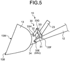
- FIG. 5 is a diagram schematically illustrating a part of the working equipment 10 according to the present embodiment, and illustrates a coupling mechanism 30 according to another embodiment.
- the coupling mechanism 30 includes a bucket pin 33E including a first rotation axis, a first link pin 33F including a second rotation axis, a second link pin 33G including a third rotation axis, and a third link pin 33H including a fourth rotation axis.
- the coupling mechanism 30 further includes a link member 31 rotatably coupled to the arm 12 via the first link pin 33F, and a link member 32 coupled to the distal end of the link member 31 via the second link pin 33G and coupled to the bracket 34 via the third link pin 33H.
- the distal end of the bucket cylinder 23 is coupled to the bucket pin 33E or the bucket 13 near the bucket pin 33E.
- a middle portion of the link member 31 is coupled to the bucket cylinder 23 via the link pin 33I.
- the bracket 34 and the bucket 13 rotate about the bucket rotation axis AXc, similarly.
- the work machine 1 performs excavation work for excavating an excavation target DS with the bucket 13 and loading work for loading the excavated object scooped by the bucket 13 in the excavation work onto the bed BE of a transport vehicle LS.
- the excavation target DS is, for example, natural ground.
- the excavated object is, for example, earth and sand.
- the transport vehicle LS is, for example, a dump truck.
- the operation modes of the work machine 1 include "V shape”, “excavation without movement”, and "scooping excavation”.
- the "V shape” means that the bucket 13 is moved in the vertical direction while the work machine 1 is moved forward or backward to perform the excavation work and the loading work. That is, the "V shape” means to perform the excavation work and the loading work with the wheels 4 rotated.
- the “Excavation without movement” means that the bucket 13 is moved in the vertical direction without moving the traveling device 3 of the work machine 1 to perform the excavation work and the loading work. That is, the “excavation without movement” means to perform the excavation work and the loading work without rotating the wheels 4.
- the "scooping excavation” means that the bucket 13 is inserted into the excavation target DS with the distal end 13B of the bucket 13 close to the ground RS, and, then, the boom 11 and the arm 12 are raised to scoop the excavation target DS with the bucket 13.
- FIG. 6 is a diagram schematically illustrating an operation of the work machine 1 according to the present embodiment, and illustrating the "V shape".
- the work machine 1 moves forward toward the excavation target DS as indicated by an arrow M1 in FIG. 6 .
- the work machine 1 excavates the excavation target DS with the bucket 13.
- the work machine 1 moves backward to be separated from the excavation target DS as indicated by an arrow M2 in FIG. 6 .
- the work machine 1 When loading the excavated object scooped by the bucket 13 onto the transport vehicle, the work machine 1 moves forward toward the transport vehicle LS while swinging as illustrated by an arrow M3 in FIG. 6 .
- the work machine 1 raises the bucket 13 while moving forward toward the transport vehicle LS.
- the work machine 1 raises at least one of the boom 11 and the arm 12 while moving forward toward the transport vehicle LS.
- the bucket 13 is positioned at a position higher than the bed BE of the transport vehicle LS.
- the work machine 1 After positioning the bucket 13 at the position higher than the bed BE of the transport vehicle LS by raising at least one of the boom 11 and the arm 12, the work machine 1 causes the bucket 13 to perform the dumping operation to discharge the excavated object from the bucket 13 to the bed BE. The excavated object is thereby loaded on the bed BE.
- the work machine 1 After discharging the excavated object from the bucket 13, the work machine 1 moves backward to be separated from the transport vehicle LS as indicated by an arrow M4 in FIG. 6 . After moving backward, the work machine 1 moves forward toward the excavation target DS as indicated by the arrow M1 in FIG. 6 . The work machine 1 repeats the above operations until the bed BE is filled with excavated objects. The above series of operations is called the "V shape".
- FIG. 7 is a diagram schematically illustrating the excavation work of the work machine 1 according to the present embodiment, and illustrating the excavation work in the "V shape".
- the work machine 1 moves forward toward the excavation target DS while appropriately including a bending operation of the vehicle body 2 according to the operation of the steering cylinder.
- the work machine 1 can move forward toward the excavation target DS with the bucket 13 separated from the ground RS.
- the work machine 1 moves forward toward the excavation target DS with the bucket 13 positioned at a position separated upward from the ground RS by a distance Ha.
- the work machine 1 raises at least one of the boom 11 and the arm 12 while moving forward toward the excavation target CS, and causes the bucket 13 to perform the tilt operation in parallel to the raising operation of at least one of the boom 11 and the arm 12.
- the work machine 1 can insert the bucket 13 into a part PH on the slope of the excavation target DS that is separated upward from the ground RS by the distance Ha.
- the distance Ha may be, for example, longer than the distance between the ground contact surface of the tires 5 and the rotation axis of the wheels 4.
- the distance Ha may be, for example, longer than the diameter of the tires 5.
- FIG. 8 is a diagram schematically illustrating the loading work of the work machine 1 according to the present embodiment, and illustrating the loading work in the "V shape".
- the work machine 1 When loading the excavated object scooped by the bucket 13 onto the bed BE of the transport vehicle LS in the "V shape" operation mode, the work machine 1 raises at least one of the boom 11 and the arm 12 while moving forward toward the transport vehicle LS. After positioning the bucket 13 at a position higher than the bed BE by raising at least one of the boom 11 and the arm 12, the work machine 1 causes the bucket 13 to perform the dumping operation to discharge the excavated object from the bucket 13 to the bed BE. In the example illustrated in FIG. 8 , the work machine 1 can raise the bucket 13 to a position separated upward from the ground RS by the sum of the distance Ha and a distance Hb to raise the bucket 13 above a vessel BE.
- the bucket 13 is positioned at a position separated from the ground RS by the distance Ha in the excavation work for excavating the excavation target DS, and the bucket 13 is positioned at a position higher than the bed BE in the loading work for loading the excavated object onto the bed BE.
- the work machine 1 is only required to move the bucket 13 in the vertical direction by the distance Hb between the excavation work and the loading work. Since the bucket 13 does not need to be greatly moved in the vertical direction, the engine and the hydraulic pump mounted on the work machine 1 do not need to output excessive power. Thus, the fuel consumption of the engine of the work machine 1 is reduced.
- the moving distance and the moving time of the bucket 13 in the vertical direction are shortened.
- the working time of the work machine 1 is prevented from becoming longer.
- the moving distance when the work machine 1 moves on the ground RS in the excavation work and the loading work is shortened.
- the work machine 1 can perform the excavation work and the loading work while repeating moving forward and backward in a small area of the ground RS.
- the work machine 1 lowers the boom 11 and the arm 12 and inserts the bucket 13 into the excavation target DS with the distal end 13B of the bucket 13 close to the ground RS, and, then, raises the boom 11 and the arm 12 to raise the bucket 13 above the work machine 1. With this operation, the excavation target DS is scooped by the bucket 13.
- the work machine 1 can excavate the excavation target DS while the bucket 13 is separated from the ground RS in the excavation work.
- the work machine 1 is only required to raise the bucket 13 by the distance Hb in the loading work. Since the work machine 1 does not need to greatly move the bucket 13 in the vertical direction between the excavation work and the loading work, the fuel consumption of the work machine 1 is reduced, and the working time of the work machine 1 is shortened.
- an existing wheel loader does not have an arm
- the wheel loader when excavating an excavation target with the bucket, the wheel loader is required to move forward toward the excavation target DS with the bucket close to the ground RS, and insert the bucket 13 near a boundary PL (see FIG. 7 ) between the ground RS and the excavation target DS.
- the wheel loader when loading the excavated object scooped by the bucket onto the bed BE of the transport vehicle LS, the wheel loader is required to raise the boom by the sum of the distance Ha and the distance Hb. That is, the existing wheel loader is required to greatly move the bucket in the vertical direction between the excavation work and the loading work. If the bucket needs to be greatly moved in the vertical direction, this requires a large power, and the fuel consumption of the wheel loader can increase. In addition, if the bucket needs to be greatly moved in the vertical direction, the moving time of the bucket becomes longer, and the working time of the wheel loader can become longer.
- the work machine 1 since the work machine 1 includes the arm 12, the work machine 1 can position the bucket 13 at a position separated upward from the ground RS by the distance Ha in the excavation work.
- the work machine 1 is only required to raise the bucket 13 by the distance Hb in the loading work, and does not need to greatly move the bucket 13 in the vertical direction. Accordingly, the fuel consumption of the work machine 1 can be reduced, and the working time can be shortened.
- the work machine 1 is an articulated work machine in which the front vehicle body 2F and the rear vehicle body 2R are coupled via the joint mechanism 9. For this reason, the work machine 1 can perform the excavation work and the loading work while repeating moving forward and backward in a small area of the ground RS, as illustrated in FIG. 6 .
- the boom 11 includes the first boom 11A and the second boom 11B
- the arm 12 includes the first arm 12A and the second arm 12B.
- a space is formed between the first boom 11A and the second boom 11B and between the first arm 12A and the second arm 12B.
- the size of the bucket 13 is larger than the size of the vehicle body 2 in the vehicle width direction. Accordingly, the bucket 13 can scoop a large amount of excavated object in one excavation work. Thus, the work efficiency of the work machine 1 is improved.
- the work machine 1 has been operated by the operator operating the operation device 8. The operator may not get on the work machine 1.
- the work machine 1 may be remotely operated, or may autonomously operate by a control device.
- the boom actuator, the arm actuator, and the bucket actuator have been the boom cylinder 21, the arm cylinder 22, and the bucket cylinder 23 that are hydraulic cylinders, respectively.
- At least one of the boom actuator, the arm actuator, and the bucket actuator may not be a hydraulic cylinder, and may include a motor and a gear.
Landscapes
- Engineering & Computer Science (AREA)
- Mining & Mineral Resources (AREA)
- Civil Engineering (AREA)
- General Engineering & Computer Science (AREA)
- Structural Engineering (AREA)
- Mechanical Engineering (AREA)
- Shovels (AREA)
- Operation Control Of Excavators (AREA)
Applications Claiming Priority (2)
| Application Number | Priority Date | Filing Date | Title |
|---|---|---|---|
| JP2018122416A JP7110008B2 (ja) | 2018-06-27 | 2018-06-27 | 作業機械 |
| PCT/JP2019/003474 WO2020003577A1 (fr) | 2018-06-27 | 2019-01-31 | Engin de chantier |
Publications (2)
| Publication Number | Publication Date |
|---|---|
| EP3712334A1 true EP3712334A1 (fr) | 2020-09-23 |
| EP3712334A4 EP3712334A4 (fr) | 2021-08-25 |
Family
ID=68984813
Family Applications (1)
| Application Number | Title | Priority Date | Filing Date |
|---|---|---|---|
| EP19826987.0A Withdrawn EP3712334A4 (fr) | 2018-06-27 | 2019-01-31 | Engin de chantier |
Country Status (3)
| Country | Link |
|---|---|
| EP (1) | EP3712334A4 (fr) |
| JP (1) | JP7110008B2 (fr) |
| WO (1) | WO2020003577A1 (fr) |
Family Cites Families (10)
| Publication number | Priority date | Publication date | Assignee | Title |
|---|---|---|---|---|
| JPS50848B1 (fr) * | 1970-07-15 | 1975-01-13 | ||
| FR2532671A1 (fr) * | 1982-09-08 | 1984-03-09 | Pingon Pierre De | Chargeur-excavateur a un seul equipement de travail |
| JPH0512364Y2 (fr) * | 1986-08-29 | 1993-03-30 | ||
| JPH09316911A (ja) * | 1996-05-30 | 1997-12-09 | Komatsu Ltd | 油圧式掘削機械の作業機装置 |
| JPH10121505A (ja) * | 1996-10-15 | 1998-05-12 | Komatsu Ltd | 油圧ショベルの作業機 |
| JP3687950B2 (ja) | 1999-07-12 | 2005-08-24 | Tcm株式会社 | ブーム装置 |
| JP4956008B2 (ja) | 2006-01-13 | 2012-06-20 | 株式会社小松製作所 | 作業機械 |
| JP4606365B2 (ja) | 2006-03-29 | 2011-01-05 | 株式会社クボタ | ローダ |
| JP2008231671A (ja) * | 2007-03-16 | 2008-10-02 | Caterpillar Japan Ltd | 作業機械 |
| US20140317967A1 (en) | 2013-04-24 | 2014-10-30 | Caterpillar Inc. | Excavator with Expanded Work Implement Compatibility |
-
2018
- 2018-06-27 JP JP2018122416A patent/JP7110008B2/ja active Active
-
2019
- 2019-01-31 EP EP19826987.0A patent/EP3712334A4/fr not_active Withdrawn
- 2019-01-31 WO PCT/JP2019/003474 patent/WO2020003577A1/fr not_active Ceased
Also Published As
| Publication number | Publication date |
|---|---|
| WO2020003577A1 (fr) | 2020-01-02 |
| JP2020002606A (ja) | 2020-01-09 |
| JP7110008B2 (ja) | 2022-08-01 |
| EP3712334A4 (fr) | 2021-08-25 |
Similar Documents
| Publication | Publication Date | Title |
|---|---|---|
| CN113348283B (zh) | 用于动力机械特别是迷你装载机的机械自调平提升臂结构 | |
| CN101311430A (zh) | 工作机 | |
| JP6625575B2 (ja) | 建設機械 | |
| US12071743B2 (en) | Coordinated actuator control by an operator control | |
| WO2013070323A1 (fr) | Engin de manutention | |
| AU2012230940B2 (en) | Surface excavation machine | |
| JP7110008B2 (ja) | 作業機械 | |
| CN113374000A (zh) | 一种推装机 | |
| WO2024176867A1 (fr) | Système comprenant une machine de travail, dispositif de commande de machine de travail et procédé de génération de trajet de machine de travail | |
| JP2024119548A (ja) | 作業機械を含むシステム、作業機械用コントローラ、および作業機械の経路生成方法 | |
| US11946222B2 (en) | Working machine | |
| JPH08128072A (ja) | ずり積込機のずり積込速度制御方法およびその装置 | |
| JPH10317421A (ja) | 油圧ショベルの上部旋回体を備えた履帯式ローダ | |
| WO2025142344A1 (fr) | Système de commande et machine de travail | |
| WO2025204619A1 (fr) | Engin de chantier, système comprenant un engin de chantier et procédé de commande d'un engin de chantier | |
| JP5752422B2 (ja) | 作業機械 | |
| CN121548670A (zh) | 具有多半径包裹件的铲斗 | |
| JP2003239325A (ja) | 旋回作業機 | |
| JPH1046632A (ja) | ショベルローダ | |
| JPH09316924A (ja) | 土木建設機械 | |
| JPH04265320A (ja) | コンベア付掘削機 | |
| JP2003239323A (ja) | 旋回作業機 | |
| JP2008002113A (ja) | 建設機械 | |
| JP2003239326A (ja) | 旋回作業機 | |
| JPH08269997A (ja) | 横方向掘削機 |
Legal Events
| Date | Code | Title | Description |
|---|---|---|---|
| STAA | Information on the status of an ep patent application or granted ep patent |
Free format text: STATUS: THE INTERNATIONAL PUBLICATION HAS BEEN MADE |
|
| PUAI | Public reference made under article 153(3) epc to a published international application that has entered the european phase |
Free format text: ORIGINAL CODE: 0009012 |
|
| STAA | Information on the status of an ep patent application or granted ep patent |
Free format text: STATUS: REQUEST FOR EXAMINATION WAS MADE |
|
| 17P | Request for examination filed |
Effective date: 20200618 |
|
| AK | Designated contracting states |
Kind code of ref document: A1 Designated state(s): AL AT BE BG CH CY CZ DE DK EE ES FI FR GB GR HR HU IE IS IT LI LT LU LV MC MK MT NL NO PL PT RO RS SE SI SK SM TR |
|
| AX | Request for extension of the european patent |
Extension state: BA ME |
|
| A4 | Supplementary search report drawn up and despatched |
Effective date: 20210722 |
|
| RIC1 | Information provided on ipc code assigned before grant |
Ipc: E02F 3/34 20060101AFI20210716BHEP Ipc: E02F 3/30 20060101ALI20210716BHEP Ipc: B60P 1/04 20060101ALI20210716BHEP Ipc: E02F 9/08 20060101ALI20210716BHEP |
|
| DAV | Request for validation of the european patent (deleted) | ||
| DAX | Request for extension of the european patent (deleted) | ||
| STAA | Information on the status of an ep patent application or granted ep patent |
Free format text: STATUS: EXAMINATION IS IN PROGRESS |
|
| 17Q | First examination report despatched |
Effective date: 20230213 |
|
| STAA | Information on the status of an ep patent application or granted ep patent |
Free format text: STATUS: THE APPLICATION HAS BEEN WITHDRAWN |
|
| 18W | Application withdrawn |
Effective date: 20230613 |