EP3713702B1 - Rohrschneidemaschine mit einem gesteuerten, fliegenden schneiddorn sowie schneideverfahren - Google Patents
Rohrschneidemaschine mit einem gesteuerten, fliegenden schneiddorn sowie schneideverfahren Download PDFInfo
- Publication number
- EP3713702B1 EP3713702B1 EP18807250.8A EP18807250A EP3713702B1 EP 3713702 B1 EP3713702 B1 EP 3713702B1 EP 18807250 A EP18807250 A EP 18807250A EP 3713702 B1 EP3713702 B1 EP 3713702B1
- Authority
- EP
- European Patent Office
- Prior art keywords
- cutting
- mandrel
- sensor
- pipe
- die
- Prior art date
- Legal status (The legal status is an assumption and is not a legal conclusion. Google has not performed a legal analysis and makes no representation as to the accuracy of the status listed.)
- Active
Links
Images





Classifications
-
- B—PERFORMING OPERATIONS; TRANSPORTING
- B26—HAND CUTTING TOOLS; CUTTING; SEVERING
- B26D—CUTTING; DETAILS COMMON TO MACHINES FOR PERFORATING, PUNCHING, CUTTING-OUT, STAMPING-OUT OR SEVERING
- B26D3/00—Cutting work characterised by the nature of the cut made; Apparatus therefor
- B26D3/16—Cutting rods or tubes transversely
- B26D3/164—Cutting rods or tubes transversely characterised by means for supporting the tube from the inside
-
- B—PERFORMING OPERATIONS; TRANSPORTING
- B23—MACHINE TOOLS; METAL-WORKING NOT OTHERWISE PROVIDED FOR
- B23D—PLANING; SLOTTING; SHEARING; BROACHING; SAWING; FILING; SCRAPING; LIKE OPERATIONS FOR WORKING METAL BY REMOVING MATERIAL, NOT OTHERWISE PROVIDED FOR
- B23D21/00—Machines or devices for shearing or cutting tubes
- B23D21/14—Machines or devices for shearing or cutting tubes cutting inside the tube
-
- B—PERFORMING OPERATIONS; TRANSPORTING
- B23—MACHINE TOOLS; METAL-WORKING NOT OTHERWISE PROVIDED FOR
- B23D—PLANING; SLOTTING; SHEARING; BROACHING; SAWING; FILING; SCRAPING; LIKE OPERATIONS FOR WORKING METAL BY REMOVING MATERIAL, NOT OTHERWISE PROVIDED FOR
- B23D33/00—Accessories for shearing machines or shearing devices
- B23D33/02—Arrangements for holding, guiding, and/or feeding work during the operation
-
- B—PERFORMING OPERATIONS; TRANSPORTING
- B23—MACHINE TOOLS; METAL-WORKING NOT OTHERWISE PROVIDED FOR
- B23D—PLANING; SLOTTING; SHEARING; BROACHING; SAWING; FILING; SCRAPING; LIKE OPERATIONS FOR WORKING METAL BY REMOVING MATERIAL, NOT OTHERWISE PROVIDED FOR
- B23D35/00—Tools for shearing machines or shearing devices; Holders or chucks for shearing tools
- B23D35/001—Tools for shearing machines or shearing devices; Holders or chucks for shearing tools cutting members
-
- B—PERFORMING OPERATIONS; TRANSPORTING
- B26—HAND CUTTING TOOLS; CUTTING; SEVERING
- B26D—CUTTING; DETAILS COMMON TO MACHINES FOR PERFORATING, PUNCHING, CUTTING-OUT, STAMPING-OUT OR SEVERING
- B26D7/00—Details of apparatus for cutting, cutting-out, stamping-out, punching, perforating, or severing by means other than cutting
- B26D7/01—Means for holding or positioning work
- B26D2007/013—Means for holding or positioning work the work being tubes, rods or logs
Definitions
- the invention relates to a pipe cutting machine according to the preamble of claim 1.
- the invention also relates to a method according to the preamble of claim 5.
- Cutting machines with mandrel mounts for a cutting eccentric drive with a variable stroke are known in the prior art.
- the disadvantage is that in the first case the mandrel has to be pushed through the entire initial length of pipe before the cutting process can begin, or that the mandrel, if it is fastened from the section side in the second case, is used to remove one or more pipe sections that have been cut to length driven away must be opened.
- the known pipe shearing methods therefore require a large proportion of the time for mandrel positioning.
- the positioning through the outlet tube is also very prone to failure, since the support rod can be very long, e.g. B. six to twelve meters.
- the resulting large, temperature-dependent longitudinal expansion and the sag are a hindrance to the exact positioning of the mandrel gap. In any case, it is imperative for the shearing process to position the mandrel gap with absolute precision.
- DE 24 30 608 discloses a cutting device with which a tube section is cut to length from a tube.
- a mandrel is pulled onto a mandrel element via a coil.
- the mandrel element rests against an adjustment ring.
- the mandrel does not need to be repositioned for a new cutting operation.
- a support element or mandrel is made available from two elements that can be separated or divided from one another, one element being made of a hardened magnetic material and the other element being made of a hardened material.
- a magnetic coil is arranged adjacent to the one element.
- the object of the invention is therefore to provide a pipe cutting machine and a method for cutting pipe sections to length, which reduce the disadvantages mentioned above.
- the object is achieved in a first aspect by a pipe cutting machine with the features of claim 1 mentioned at the outset.
- a pipe cutting machine is also to be understood as a pipe shearing machine.
- a tube is preferably to be understood as meaning a longitudinal profile which has a circular outer circumference in cross section and a circular inner circumference in cross section and which is preferably paramagnetic or diamagnetic here.
- the pipe cutting machine here comprises the already threaded pipe from which a pipe section is to be cut to length, and a die cutter with a fixed cutting die and a cutting die that can be moved relative to the fixed cutting die, as well as a cutting mandrel that is introduced into the pipe, which has a stationary mandrel and a dem having stationary mandrel versus movable mandrel.
- the cutting mandrel is positioned inside the pipe during the cutting process.
- a mandrel gap i.e. a distance between a flat end of the stationary mandrel and a flat end of the movable mandrel, is smaller than the radially extended die gap and along the entire circumference of the tube within the radially extended die gap, i.e. the distance between the fixed and the movable cutting die arranged.
- the cutting die is preferably driven with an eccentric drive in an eccentric movement in relation to the stationary cutting die, this is a spirally increasing movement, ie a movement with a variable stroke. This eccentric movement allows the pipe section to be separated from the pipe.
- the movable cutting die is preferably connected to the eccentric drive;
- a feed device for example in the form of a movable gripper, is provided, which feeds the pipe in the pipe cutting machine exactly by the desired length.
- the tube is incrementally advanced during indexed cutting operations.
- a controlled, flying cutting mandrel is arranged in the pipe, and a magnetic coupling is provided with one arranged outside the pipe Clutch stator and arranged on the stationary mandrel clutch rotor which cooperates with the clutch stator.
- the magnetic coupling forms a magnetic field between the clutch rotor and the clutch stator.
- a displacement of the magnetic field in the longitudinal direction can be controlled by control values.
- the shifting of the magnetic field can be effected in various ways.
- a position sensor is provided with a sensor stator connected in a fixed position to the frame of the pipe cutting machine and a sensor rotor fixed in a position to the stationary mandrel, with which axial deviations of the cutting mandrel from the cutting position can be measured, and a control unit is provided, the measured deviation values that the position sensor determined, converted into the control values.
- the control values are supplied to the control unit, by means of which the cutting mandrel can be moved back into the cutting position.
- the invention makes use of the idea of no longer positioning the cutting mandrel with a rod that is guided through one or the other pipe end, but completely dispensing with this mechanical connection and instead providing the magnetic coupling that holds the flying cutting mandrel in position , and to provide a position sensor that measures this as a change when the magnetic clutch is adjusted and corrects it via the control unit.
- the magnetic coupling preferably has a row of ring-shaped permanent magnets in the clutch stator arranged outside around the pipe, while the clutch rotor, which is part of the flying cutting mandrel, also has a row of preferably ring-shaped permanent magnets, which are designed with opposite poles to the associated magnets of the clutch stator and thus pull the mandrel to a cutting position by a magnetic force developing through the pipe wall.
- the magnets, preferably ring magnets, of the magnetic coupling and of the position sensor can also be designed as electric magnets. Appropriate electrical connections for the coils must then be provided.
- the magnets of the flying cutting mandrel can also be in the form of permanent magnets and the outer magnets of the sensor stator and clutch stator can be in the form of electrical magnets, from and to which electrical lines can easily be laid.
- the magnetic coupling is adjustable in the axial direction, for example in that the entire housing of the clutch stator in the axial direction in the formation of permanent magnets direction can be moved. If the magnets are formed by electric magnets, coils can be switched in such a way that the magnetic field shifts back and forth in the axial direction. In both cases, the magnetic field of the magnetic coupling can be shifted in the axial direction in order to realign the position of the cutting mandrel relative to the die cutting edge or to align it correctly initially.
- the displacement of the magnetic field of the magnetic coupling is determined by control values that are determined by readings from the position sensor.
- the position sensor preferably has a sensor rotor which has at least two magnets spaced apart from one another in the longitudinal direction.
- the sensor stator has at least two sensor rings, each with at least two Hall sensors. Due to the axial displacement of the magnets in the axial longitudinal direction, changing magnetic field strengths are measured by the Hall sensors. The measured values are determined and preferably processed and fed to the magnetic clutch as control values.
- the Hall sensors are favorably connected to the control unit, which assigns measured values of the Hall sensors of a sensor ring to a sensor ring measured value and from changes in sensor ring measured value differences calculates a deviation of the cutting mandrel from the cutting position and generates the measured deviation values.
- average values preferably weighted average values, can be formed from the measured values of the Hall sensors of a sensor ring and these can be fed to the control unit as sensor measured value.
- each sensor ring thus led to a sensor ring measured value, and when the cutting mandrel is displaced, each sensor ring generates different sensor ring measured values by displacing the magnets of the cutting mandrel relative to the sensor stator, and the displacement of the cutting mandrel from the cutting position can be calculated from the sensor ring measured value differences.
- Corresponding control values are determined and the displacement of the cutting mandrel is reversed by corresponding displacement of the magnetic field of the magnetic coupling.
- the object is also achieved by a method for cutting pipe sections to length of the type mentioned at the beginning with the features of claim 5 .
- a flying cutting mandrel is inserted into the tube, the tube is inserted into a die cutting edge until a cut surface between the tube section and tube is arranged in the extension of the die gap and the flying cutting mandrel is aligned in its axial position and shifted into a cutting position in which a cutting mandrel gap placed within the extension of the die gap.
- the method is particularly suitable for implementation with one of the pipe cutting machines mentioned at the outset.
- the pipe cutting machines mentioned at the beginning are all suitable for carrying out the method mentioned or the following ones.
- a position sensor measures displacements of the cutting mandrel from a cutting position, which feeds measured values to the control unit, which determines the displacement measurement values and converts them into control values and feeds them to a magnetic clutch, which moves the cutting mandrel back into its cutting position.
- measured values from Hall sensors arranged along a measuring ring are measured and calculated into a sensor ring measured value, and the sensor ring measured values of at least two measuring rings are determined and compared with sensor ring measured values of a cutting position, and the displacement measured values are calculated from the comparison.
- the displacement measurements can then be converted into said control measurements by the control unit.
- the measured values of the Hall sensors of a measuring ring are advantageously calculated by averaging the individual measured values of the Hall sensors.
- the averaging can also be weighted.
- differences between the averaged measured values can be calculated and compared with the differences in the averaged measured values of the cutting position, and the displacement measured values can be calculated from these differences.
- the die 1 shows part of a pipe cutting machine.
- the actual cutting process is carried out in the pipe cutting machine by a die cutter with two cooperating cutting dies 1, 2. Cutting is also understood here as shearing.
- the die cutting edge has the stationary cutting die 1 and the movable cutting die 2 .
- the stationary cutting die 1 is arranged in a fixed position relative to a frame or housing of the cutting machine, not shown, even during the cutting process or shearing process.
- the movable cutting die 2 is movable relative to the fixed cutting die 1 parallel to a cutting plane.
- the movable cutting die 2 is driven by an eccentric drive, which is also not shown, and therefore performs an eccentric movement about a longitudinal axis L of a tube 3 inserted into the stationary cutting die 1 .
- the eccentric movement leads to an increasing spiral cutting movement, with which a pipe section 3a is sheared off the pipe 3.
- a magnetic coupling 6 is provided with an in 1 visible clutch stator 7 placed around the outside of the tube, which is equipped with an in 1 not yet shown, arranged inside the clutch rotor, which is part of a flying cutting mandrel, interacts.
- a position sensor 8 is arranged on the side of the magnetic coupling 6 opposite the die cutting edge, through which the tube 3 is also threaded. Before the cutting process, the tube 3 is first passed through the position sensor 8, then through the magnetic coupling 6 and then through the two cutting dies 1, 2 through through holes 1a, 2a provided for this purpose. In 1 the already threaded state is shown.
- three sensor rings 9, 10, 11 are arranged. Each of the sensor rings 9, 10, 11 has six Hall sensors 91, 92, 93, 94, 95, 96, 101, 102, 103, 104, 105, 106, 111, 112, 113, 114, 115, 116.
- the position sensor 8 includes an in 1 illustrated sensor stator 12, which is arranged on the outside around the pipe 3, and a sensor rotor 19 designed as part of a flying cutting mandrel 13.
- the clutch stator 7 can be arranged in a fixed position relative to the frame of the pipe cutting machine. However, it can also be designed to be movable back and forth by means of a linear motor.
- a controller is provided which makes it possible to shift magnetic fields formed by the clutch stator 7 back and forth in the longitudinal direction L of the tube 3, which corresponds to an axial direction.
- this displacement of the magnetic field is taken over by the linear motor, which displaces the magnetic fields in the clutch stator 7 .
- the shift is represented by the double arrow.
- Both cutting dies 1, 2 each have the same-sized, cylindrical hole 1a, 2a with an inner diameter that corresponds to an outer diameter of the tube 3, the two holes 1a, 2a in 2 are arranged congruently, so that one end of the tube 3 is threaded through both holes 1a, 2a at the same time.
- the flying mandrel 13 is already arranged in a cutting position. The flying cutting mandrel 13 is not led out to the outside at either end of the pipe 3 in order to connect it to the frame, a guide rod or other devices of the pipe cutting machine. In principle, the cutting mandrel 13 can be freely moved back and forth in the longitudinal direction L of the pipe 3 .
- the cutting mandrel 13 has a stationary mandrel 14 and a movable mandrel 16 .
- the movable mandrel 16 is designed to be movable in all directions perpendicular to the longitudinal direction L relative to the stationary mandrel 14 .
- the movable mandrel 14 absorbs the forces of the movable cutting die 2 at a On the inside of the wall and guides it through the inside of the pipe section 3a to be cut to length onto an opposite wall inside of the pipe section 3a to be cut to length, so that when the movable cutting die 2 moves from top to bottom, as shown in FIG Figure 3a as shown, the top and bottom of the pipe section 3a are sheared off the pipe.
- the lateral areas are initially deformed somewhat.
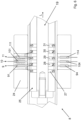
- Fig.2 shows the pipe 3 in the cutting position in which the die gap 17 and the cutting mandrel gap 18 lie directly one above the other. Center planes of the two columns 17, 18 coincide.
- Figure 3a shows the flying mandrel 13 in a deflected state during the shearing process.
- the movable mandrel 14 is deflected downwards.
- the detail view in Figure 3b shows that in order to carry out the cutting movement, it is important that a die gap 17 between the fixed cutting die 1 and the movable cutting die 2, which is approximately 0.2 mm +/- 0.05 mm, defines an area surrounding the tube 3 , within which a cutting mandrel gap 18 between the movable mandrel 16 and the mandrel 14 lies.
- the cutting mandrel gap here is about 0.01 mm +/-0.005 mm. Otherwise the cutting dies 1, 2 would be damaged when sheared off.
- the exact positioning of the flying cutting mandrel 13 in the tube 3 is achieved according to the invention by the position sensor 8 in connection with the magnetic coupling 6 .
- the position sensor 8 has the sensor stator 12 laid around the outside of the pipe and the sensor runner 19 which is designed as a section of the cutting mandrel 13 and which is arranged on the end of the cutting mandrel 13 opposite the movable mandrel 16 .
- the position sensor 8 and magnetic coupling 6 can also be interchanged on the cutting mandrel 13 .
- the magnetic coupling 6 consists of the coupling stator 7, which can be arranged so that it can be moved relative to the frame of the pipe cutting machine, or the magnetic fields can be moved back and forth by means of a linear motor.
- the clutch stator 7 interacts with a clutch rotor 21 which also forms a section of the cutting mandrel 13 .
- the magnetic coupling is formed by two rows of magnets.
- the clutch stator 7 has a first row of ring magnets 71, 72 arranged one behind the other, which alternately form north and south poles pointing inwards.
- the clutch rotor 21 has a second row of magnets 211, 212 on, but which are arranged in reverse, so that a coupling behavior is established and the cutting mandrel 13 is automatically pulled by the two rows of magnets into the cutting position in which the magnets of the two rows of magnets assume the smallest distance from one another.
- the magnetic coupling 6 is therefore primarily suitable for cutting non-ferromagnetic pipes made entirely of stainless steel, brass, copper and titanium or mixtures thereof; in principle, ferromagnetic tubes 3 could also be cut if the magnets are strong enough.
- the position of the magnetic coupling 6, ie the coupling stator 7, at a distance from the die cutting edge 1 is set with regard to the dimensions of the cutting mandrel 13.
- temperature influences that affect the machine and the changes in length in the area of the in Figure 3b shown dimensions of tenths of a millimeter can cause slight shifts, but hinder or even prevent the shearing process.
- the position of the flying mandrel 13 relative to the stationary cutting die 1, in particular of the cutting mandrel gap 18 relative to the die gap 17, is constantly or regularly checked with the aid of the position sensor 8.
- the position sensor 8 in Figure 3a has the three sensor rings 9, 10, 11, each with the six Hall sensors 91, 92, 93, 94, 95, 96, 101, 102, 103, 104, 105, 106, 111, 112, 113, 114, 115, 116 , as shown in the sectional view in 4 , shown on the first sensor ring 9 are shown.
- the other sensor rings 10, 11 are identical in construction to the first sensor ring 9. It is also conceivable that each of the sensor rings 9, 10, 11 has two or four or a higher number of Hall sensors 91, 92, 93, 94, 95, 96 , 101, 102, 103, 104, 105, 106, 111, 112, 113, 114, 115, 116.
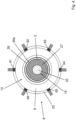
- the six Hall sensors 91, 92, 93, 94, 95, 96 which are offset by 60°, are shown.
- the six Hall sensors 91, 92, 93, 94, 95, 96 of the first sensor ring 9 are embedded in a circumferential iron ring 23, the sensor rings 9, 10, 11 are in a guide sleeve 24 according to figure 5 guided.
- the guide sleeve 24 has a cylindrical opening 25 which corresponds to the outer diameter of the pipe and through which the pipe 3 is threaded.
- a small clearance 26 of the size of a fraction of a millimeter is provided between the outer wall of the tube and the guide sleeve 24 of the sensor stator 12 so that the tube 3 can also be threaded through the cylindrical opening 25 of the sensor stator 12 .
- the sensor rotor 19 is provided inside the tube 3 .
- a permanent magnet ring 27 is shown in section, which represents a north pole on the outside.
- the permanent magnet ring 27 is threaded onto a non-magnetic, ie paramagnetic or diamagnetic holding rod 22 .
- An outer diameter of the permanent magnet ring 27 corresponds to the inner diameter of the tube 3, also minus a small play of a fraction of a millimeter.
- figure 5 shows five permanent magnet rings 27, 28, 29, 30, 31 according to 4 .
- the interaction of the permanent magnet rings 27, 28, 29, 30, 31 of the sensor rotor 19 and the Hall sensors 91, 92, 93, 94, 95, 96, 101, 102, 103, 104, 105, 106, 111, 112, 113 114 115, 116 of the sensor stator 12 is in the figure 5 , 6 and 7 shown with associated magnetic field lines.
- Each of the Hall sensors 91, 92, 93, 94, 95, 96, 101, 102, 103, 104, 105, 106, 111, 112, 113, 114, 115, 116 measures the magnetic field strength at the radially outer end of the sensor ring 9 assigned to them , 10, 11, i.e. where the Hall sensors 91, 92, 94, 95, 96, 101, 102, 103, 104, 105, 106, 111, 112, 113 114 115, 116 4 are arranged.
- figure 5 shows the formation of the magnetic field lines in the cutting position, this is the position when according to 2 and Figure 3b the cutting mandrel gap 18 is located entirely within the die cutting gap 17 . It can be seen that sensor 101 receives no signal while sensors 91 and 111 receive a relatively strong signal.
- the associated measured values are in the 8 shown on the zero line. In fact, it is not the measured values of a single Hall sensor in 8 are applied and fed to a control unit. Since the permanent magnet rings 27, 28, 29, 30, 31 of the sensor rotor 19 can also be moved perpendicularly to the longitudinal direction L due to the play and the Hall sensors 91, 92, 93, 94, 95, 96, 101, 102, 103, 104, 105, 106, 111, 112, 113, 114, 115, 116 are extremely sensitive to changes in magnetic field strength, a weighted or simple, unweighted mean value of the Hall sensors 91, 92, 93, 94, 95, 96, 101, 102, 103 is conveniently used , 104, 105, 106, 111, 112, 113, 114, 115, 116 of a sensor ring 9, 10, 11 are formed.
- FIG. 6 shows the magnetic field lines when the flying cutting mandrel 13 is displaced in the direction of the cutting die 1.
- the displacement of the permanent magnet rings 27, 28, 29, 30, 31 creates a strong magnetic field on the sensor ring 10, while the magnetic fields on the Hall sensors 91, 92, 93, 94, 95, 96, 111, 112, 113 114 115, 116 of the sensor rings 9 and 11. This is in the 8 in the position " 6 " shown, corresponding to the position of the 6 is equivalent to.
- the cutting mandrel 13 is moved away from the cutting die 1.
- the sensor ring 10 receives a maximum measurement signal, but in exactly the opposite direction, since the field lines are opposite to that 6 have reversed their direction, while the sensor rings 9 and 11 again experience a weak signal, also in the opposite direction.
- the measured values are also shown.
- the three sensor rings 9, 10, 11 would result in a sinusoidal course of measured values, as is shown in FIG 8 is shown.
Landscapes
- Engineering & Computer Science (AREA)
- Mechanical Engineering (AREA)
- Life Sciences & Earth Sciences (AREA)
- Forests & Forestry (AREA)
- Manufacture Of Motors, Generators (AREA)
- Turning (AREA)
- Machine Tool Sensing Apparatuses (AREA)
- Accessories And Tools For Shearing Machines (AREA)
- Linear Motors (AREA)
- Sawing (AREA)
Description
- Die Erfindung betrifft eine Rohrschneidemaschine nach dem Oberbegriff des Anspruchs 1.
- Eine solche Rohrschneidemaschine ist aus
DE 24 30 608 A bekannt. - Die Erfindung betrifft ebenfalls ein Verfahren nach dem Obergriff des Anspruchs 5.
- Ein solches Verfahren ist aus
DE 10 2010 061191 A bekannt. - Nach dem Stand der Technik sind Schneidemaschinen mit Dornhalterungen für einen Schneidexzenterantrieb mit variablem Hub bekannt.
- Für Rohrscherverfahren ist es erforderlich, einen Schneiddorn im abzulängenden Rohr derart zu positionieren, dass ein Schneiddornspalt exakt in Achsrichtung des Rohres innerhalb des Schneidspaltes zweier Schneidmatrizen liegt. Im Stand der Technik ist es bekannt, den Schneiddorn durch das Rohr hindurch mit einer Stange mit einer Einstellvorrichtung zu verbinden und auf Position zu halten und für den nachfolgenen Schneidtakt vorzuschieben. Die Stange zur axialen Befestigung und die Positionierung des Schneiddorns können wahlweise von der Rohrzuführungsseite oder von der Rohrschnittseite erfolgen. Nachteilig ist jedoch, dass der Dorn im ersten Fall durch die gesamte Rohrausgangslänge durchgeschoben werden muss, bevor der Schneidvorgang beginnen kann, oder dass der Dorn, wenn er im zweiten Fall von der Abschnittsseite her befestigt ist, zur Entnahme von einem oder von mehreren abgelängten Rohrabschnitten weggefahren geöffnet werden muss. Die bekannten Rohrscherverfahren benötigen deshalb einen großen Zeitanteil für die Dornpositionierung. Die Positionierung durch das Ausgangsrohr ist zusätzlich sehr störanfällig, da die Haltestange sehr lang sein kann, z. B. sechs bis zwölf Meter. Die dadurch entstehende große temperaturabhängige Längsausdehnung und der Durchhang sind für die exakte Positionierung des Dornspaltes hinderlich. In jedem Fall ist es für das Scherverfahren zwingend erforderlich, den Dornspalt absolut exakt zu positionieren.
- In der
DE 10 2010 061 191 A1 ist eine Schneidemaschine mit einer feststehenden Schneidmatrize offenbart, die mit einem Dornteil über einem Bolzen positionsfest verbunden ist. - In der
DE 24 30 608 ist eine Schneidvorrichtung offenbart, mit der ein Rohrabschnitt von einem Rohr abgelängt wird. Hier wird ein Dorn über eine Spule an ein Dornelement herangezogen. Das Dornelement liegt an einem Einstellring an. Der Dorn braucht nicht für einen neuen Schneidvorgang neu positioniert zu werden. - Aus der
DE 2 430 608 A1 ist ein Verfahren zum Abschneiden von Werkstücken bekannt. Dabei wird ein Stützelement oder Dorn aus zwei voneinander trenn- oder teilbaren Elementen zur Verfügung gestellt, wobei das eine Element aus einem gehärteten magnetischen Material hergestellt ist, das andere Element aus einem gehärteten Material besteht. Angrenzend an das eine Element ist eine Magnetspule angeordnet. - Aus der
US 4,889,023 ist eine Rohrschneidemaschine mit fliegend gelagertem Dorn bekannt, bei dem der Dorn über ein Magnetfeld positioniert wird. - Aufgabe der Erfindung ist es daher, eine Rohrschneidemaschine und ein Verfahren zum Ablängen von Rohrabschnitten zur Verfügung zu stellen, die bzw. das die oben genannten Nachteile verringern.
- Die Aufgabe wird in einem ersten Aspekt durch eine eingangs genannte Rohrschneidemaschine mit den Merkmalen des Anspruchs 1 gelöst.
- Zunächst ist hier unter einer Rohrschneidemaschine auch eine Rohrschermaschine zu verstehen. Unter einem Rohr ist vorzugsweise ein im Querschnitt einen kreisförmigen Außenumfang und im Querschnitt einen kreisförmigen Innenumfang aufweisendes Längsprofil zu verstehen, das hier vorzugsweise para- oder diamagnetisch ist.
- Die Rohrschneidemaschine umfasst hier das bereits eingefädelte Rohr, von dem ein Rohrabschnitt abgelängt werden soll, und eine Matrizenschneide mit einer feststehenden Schneidmatrize und einer gegenüber der feststehenden Schneidmatrize beweglichen Schneidmatrize sowie einen Schneiddorn, der in das Rohr eingebracht ist, der einen stationären Dorn und einen dem stationären Dorn gegenüber beweglichen Dorn aufweist.
- Der Schneiddorn ist während des Schneidvorganges im Inneren des Rohres angeordnet. Dabei ist ein Dornspalt, also ein Abstand zwischen einem flächigen Ende des stationären Dornes und einem flächigen Ende des beweglichen Dornes, kleiner als der radial verlängerte Matrizenspalt und entlang des gesamten Umfanges der Rohres innerhalb des radial verlängerten Matrizenspaltes, also des Abstandes zwischen der positionsfesten und der beweglichen Schneidmatrize, angeordnet. Die Schneidmatrize wird vorzugsweise mit einem Exzenterantrieb in einer exzentrischen Bewegung gegenüber der feststehenden Schneidmatrize angetrieben, das ist eine spiralförmig größer werdende Bewegung, also eine Bewegung mit variablem Hub. Durch diese exzentrische Bewegung kann der Rohrabschnitt vom Rohr abgetrennt werden.
- Vorzugsweise ist die bewegliche Schneidmatrize mit dem Exzenterantrieb verbunden; darüber hinaus ist eine Vorschubvorrichtung, beispielsweise in Form eines beweglichen Greifers, vorgesehen, der das Rohr in der Rohrschneidemaschine um die gewünschte Ablänglänge exakt vorschiebt. Das Rohr wird während der getakteten Schneidvoränge schrittweise vorgeschoben.
- Erfindungsgemäß ist ein gesteuerter, fliegender Schneiddorn im Rohr angeordnet, und es ist eine Magnetkupplung vorgesehen mit einem außerhalb des Rohres angeordneten Kupplungsstator und einem am stationären Dorn angeordneten Kupplungsläufer, der mit dem Kupplungsstator zusammenwirkt. Die Magnetkupplung bildet ein Magnetfeld zwischen Kupplungsläufer und Kupplungsstator aus. Eine Verschiebung des Magnetfeldes in Längsrichtung ist durch Steuerwerte steuerbar ist. Die Verschiebung des Magnetfeldes kann auf verschiedene Arten bewirkt werden.
- Des Weiteren ist ein Lagesensor mit einem am Gestell der Rohrschneidemaschine positionsfest verbundenen Sensorstator und einem mit dem stationären Dorn positionsfest verbundenen Sensorläufer vorgesehen, mit der axiale Abweichungen des Schneiddornes aus der Schneidstellung messbar sind, und es ist eine Steuereinheit vorgesehen, die Abweichungsmesswerte, die der Lagesensor ermittelt, in die Steuerwerte umwandelt. Die Steuerwerte werden der Steuereinheit zugeführt, durch die der Schneiddorn in die Schneidstellung zurückbewegbar ist.
- Die Erfindung macht von der Idee Gebrauch, den Schneiddorn nicht mehr durch eine Stange die durch das eine oder das andere Rohrende geführt ist zu positionieren, sondern auf diese mechanische Verbindung vollständig zu verzichten und statt dessen die Magnetkupplung vorzusehen, die den fliegenden Schneiddorn auf Position hält, und dazu einen Lagesensor vorzusehen, der bei Verstellung der Magnetkupplung dies als Änderung misst und über die Steuereinheit korrigiert.
- Die Magnetkupplung weist im außen um das Rohr angeordneten Kupplungsstator vorzugsweise eine Reihe von ringförmigen Permanentmagneten auf, während der Kupplungsläufer, der Teil des fliegenden Schneiddornes ist, ebenfalls eine Reihe von vorzugsweise ringförmigen Permanentmagneten aufweist, die mit entgegengesetzten Polen zu den zugeordneten Magneten des Kupplungsstators ausgebildet sind und so den Schneiddorn durch eine sich durch die Rohrwandung hindurch ausbildende magnetische Kraft auf eine Schneidposition ziehen. Die Magneten vorzugsweise Ringmagneten der Magnetkupplung als auch des Lagesensors können auch als elektrische Magneten ausgebildet sein. Es sind dann entsprechende elektrische Anschlüsse für die Spulen vorzusehen. Es können auch die Magneten des fliegenden Schneiddornes als Permanentmagneten und die äußere Magneten der Sensorstators und Kupplungsstators als elektrische Magneten ausgebildet sein, von und zu denen leicht elektrische Leitungen verlegt werden können.
- Die Magnetkupplung ist in axialer Richtung verstellbar, beispielweise dadurch, dass bei der Ausbildung durch Permanentmagnete das gesamte Gehäuse des Kupplungsstators in axialer Richtung verschiebbar ist. Bei Ausbildung der Magneten durch elektrische Magneten können Spulen so geschaltet werden, dass sich das Magnetfeld in axialer Richtung hin und her verschiebt. In beiden Fällen ist das Magnetfeld der Magnetkupplung in axialer Richtung verschiebbar, um damit den Schneiddorn in seiner Position relativ zur Matrizenschneide neu oder anfänglich einmal richtig auszurichten.
- Die Verschiebung des Magnetfeldes der Magnetkupplung wird durch Steuerwerte bestimmt, die durch Messwerte des Lagesensors bestimmt werden. Der Lagesensor weist vorzugsweise einen Sensorläufer auf, der wenigstens zwei in Längsrichtung voneinander beabstandete Magnete aufweist. Der Sensorstator weist wenigstens zwei Sensorringe mit jeweils wenigstens zwei Hall-Sensoren auf. Durch die axiale Verschiebung der Magnete in axialer Längsrichtung werden sich verändernde Magnetfeldstärken durch die Hall-Sensoren gemessen. Die Messwerte werden ermittelt und vorzugsweise verarbeitet und als Steuerwerte der Magnetkupplung zugeführt.
- Günstigerweise sind die Hall-Sensoren mit der Steuereinheit verbunden, die Messwerten der Hall-Sensoren eines Sensorringes jeweils einen Sensorringmesswert zuordnet und aus Veränderungen von Sensorringmesswertdifferenzen eine Abweichung des Schneiddorns aus der Schneidlage berechnet und die Abweichungsmesswerte erzeugt. Vorzugsweise können aus den Messwerten der Hall-Sensoren eines Sensorringes Durchschnittswerte, vorzugsweise gewichtete Durchschnittswerte gebildet werden und diese als Sensormesswert der Steuereinheit zugeführt werden. Jeder Sensorring führte somit zu einem Sensorringmesswert, und bei Verschiebung des Schneiddornes erzeugt jeder Sensorring durch Verschiebung der Magnete des Schneiddornes gegenüber dem Sensorstator andere Sensorringmesswerte, und aus den Sensorringmesswertdifferenzen kann die Verschiebung des Schneiddornes aus der Schneidlage berechnet werden. Entsprechende Steuerwerte werden ermittelt, und die Verschiebung des Schneiddornes wird durch entsprechendes Verschieben des Magnetfeldes der Magnetkupplung rückgängig gemacht.
- Die Aufgabe wird auch durch ein Verfahren zum Ablängen von Rohrabschnitten der eingangs genannten Art mit den Merkmalen des Anspruchs 5 erfüllt.
- Erfindungsgemäß wird ein fliegender Schneiddorn in das Rohr eingeführt, das Rohr in eine Matrizenschneide eingeführt, bis eine Schnittfläche zwischen Rohrabschnitt und Rohr in Verlängerung des Matrizenspaltes angeordnet wird und der fliegende Schneiddorn in seiner axialen Position ausgerichtet und in eine Schneidposition verschoben wird, in der ein Schneiddornspalt innerhalb der Verlängerung des Matrizenspaltes angeordnet wird.
- Das Verfahren eignet sich insbesondere zur Durchführung mit einer der eingangs genannten Rohrschneidemaschinen. Umgekehrt eignen sich die eingangs genannten Rohrschneidemaschinen alle zur Durchführung des genannten oder der nachfolgenden Verfahren.
- Ein Lagesensor misst Verschiebungen des Schneiddornes aus einer Schneidposition, der der Steuereinheit Messwerte zuführt, die die Verschiebungsmesswerte ermittelt und diese in Steuerwerte umwandelt und einer Magnetkupplung zuführt, die den Schneiddorn in seine Schneidposition zurückverschiebt.
- Vorzugsweise werden Messwerte von entlang eines Messringes angeordneten Hall-Sensoren gemessen und zu einem Sensorringmesswert verrechnet, und die Sensorringmesswerte wenigstens zweier Messringe werden ermittelt und mit Sensorringmesswerten einer Schneidstellung verglichen, und aus dem Vergleich werden die Verschiebungsmesswerte berechnet. Die Verschiebungsmesswerte können dann durch die Steuereinheit in die genannten Steuermesswerte umgewandelt werden.
- Günstigerweise werden die Messwerte der Hall-Sensoren eines Messringes durch Mittelung der einzelnen Messwerte der Hall-Sensoren berechnet. Dabei kann die Mittelung auch gewichtet erfolgen.
- Zur Auswertung der gemittelten Messwerte können Differenzen zwischen den gemittelten Messwerten berechnet werden und mit den Differenzen der gemittelten Messwerte der Schneidposition verglichen werden und aus diesen Differenzen die Verschiebungsmesswerte berechnet werden.
- Die Erfindung wird anhand eines Ausführungsbeispiels in neun Figuren beschrieben. Dabei zeigen:
-
Fig. 1 eine perspektivische Ansicht einer Matrizenschneide, einer Magnetkupplung und eines Lagesensors mit einem eingefädelten Rohr, in dem ein fliegender Schneiddorn angeordnet ist, -
Fig. 2 eine Schnittansicht der Anordnung inFig. 1 entlang der Linie II - II inFig. 1 mit einem Schnitt des in das Rohr eingebrachten Schneiddornes, -
Fig. 3a eine Schnittansicht inFig. 2 mit ausgelenkter, beweglicher Schneidmatrize und dem einen vom Rohr abgelängten Rohrabschnitt, -
Fig. 3b eine Detailansicht inFig. 3a mit der Darstellung der relativen Größe von einem Schneiddornspalt und einem Matrizenschneidspalt, -
Fig. 4 eine Schnittansicht entlang der Linie IV - IV inFig. 1 mit der Anordnung von sechs Hall-Sensoren am Sensorstator, -
Fig. 5 eine Funktionsdarstellung des Lagesensors mit Sensorstator und Sensorläufer in der Schneidstellung mit eingezeichneten Magnetfeldlinien, -
Fig. 6 eine Darstellung gemäßFig. 5 mit nach links aus der Schneidstellung herausbewegtem Schneiddorn und zugehörigen Magnetfeldlinien, -
Fig. 7 eine Darstellung gemäßFig. 5 mit nach rechts aus der Schneidstellung herausbewegtem Schneiddorn mit zugehörigen Magnetfeldlinien, -
Fig. 8 eine Graphik von Messwerten der drei in denFiguren 5 ,6 und7 dargestellten Sensorringen mit Hall-Sensoren bei Verschiebung nach links und rechts aus der Schneidposition des Schneiddorns. -
Fig. 1 zeigt einen Teil einer Rohrschneidemaschine. Der eigentliche Schneidvorgang wird bei der Rohrschneidemaschine durch eine Matrizenschneide mit zwei zusammenwirkenden Schneidmatrizen 1, 2 durchgeführt. Unter Schneiden wird hier auch ein Scheren verstanden. Die Matrizenschneide weist die feststehende Schneidmatrize 1 und die bewegliche Schneidmatrize 2 auf. Die feststehende Schneidmatrize 1 ist gegenüber einem nicht dargestellten Gestell oder Gehäuse der Schneidmaschine auch während des Schneidvorganges oder Schervorganges positionsfest angeordnet. Die bewegliche Schneidmatrize 2 ist gegenüber der feststehenden Schneidmatrize 1 parallel zu einer Schneidebene beweglich. Die bewegliche Schneidmatrize 2 wird von einem Exzenterantrieb, der ebenfalls nicht dargestellt ist, angetrieben und führt daher eine exzentrische Bewegung um eine Längsachse L eines in die feststehende Schneidmatrize 1 eingeführten Rohres 3 durch. Die exzentrische Bewegung führt zu einer größer werdenden spiralförmigen Schneidbewegung, mit der ein Rohrabschnitt 3a vom Rohr 3 abgeschert wird. - Darüber hinaus ist erfindungsgemäß eine Magnetkupplung 6 vorgesehen mit einem in
Fig. 1 sichtbaren, außen um das Rohr gelegten Kupplungsstator 7, der mit einem inFig. 1 noch nicht dargestellten, im Inneren angeordneten Kupplungsläufer, der Teil eines fliegenden Schneiddornes ist, zusammenwirkt. - In
Fig. 1 ist auf der der Matrizenschneide gegenüberliegenden Seite von der Magnetkupplung 6 ein Lagesensor 8 angeordnet, durch den das Rohr 3 ebenfalls hindurchgefädelt ist. Das Rohr 3 wird vor dem Schneidvorgang zunächst durch den Lagesensor 8, dann durch die Magnetkupplung 6 und dann durch die beiden Schneidmatrizen 1, 2 durch dafür vorgesehene durchgehende Löcher 1a, 2a hindurchgeführt. InFig. 1 ist der bereits eingefädelte Zustand dargestellt. An dem Lagesensor 8 sind drei Sensorringe 9, 10, 11 angeordnet. Jeder der Sensorringe 9, 10, 11 weist sechs Hall-Sensoren 91, 92, 93, 94, 95, 96, 101, 102, 103, 104, 105, 106, 111, 112, 113 114 115, 116 auf. Der Lagesensor 8 umfasst einen inFig. 1 dargestellten, außen um das Rohr 3 angeordneten Sensorstator 12 sowie einen als Teil eines fliegenden Schneiddorns 13 ausgebildeten Sensorläufer 19. - Der Kupplungsstator 7 kann relativ zum Gestell der Rohrschneidemaschine positionsfest angeordnet sein. Er kann jedoch auch mittels eines Linearmotors hin und her verfahrbar ausgebildet sein. Im ersten Fall ist eine Steuerung vorgesehen, die es ermöglicht, vom Kupplungsstator 7 ausgebildete Magnetfelder in Längssrichtung L des Rohres 3, die einer axialen Richtung entspricht, hin und her zu verschieben. Im zweiten Fall übernimmt diese Verschiebung des Magnetfeldes der Linearmotor, der die Magnetfelder im Kupplungsstator 7 verschiebt. Die Verschiebung ist durch den Doppelpfeil dargestellt.
-
Fig. 2 zeigt die Schnittansicht derFig. 1 entlang der Linie II-II. Beide Schneidmatrizen 1, 2 weisen jeweils das gleichgroße, zylindrische Loch 1a, 2a auf mit einem Innendurchmesser der einem Außendurchmesser des Rohres 3 entspricht, wobei die beiden Löcher 1a, 2a inFig. 2 deckungsgleich angeordnet sind, so dass ein Ende des Rohres 3 durch beide Löcher 1a, 2a gleichzeitig durchgefädelt ist. In dem Rohr 3 ist der fliegende Schneiddorn 13 bereits in einer Schneidstellung angeordnet. Der fliegende Schneiddorn 13 ist weder an dem einen noch an dem anderen Ende des Rohres 3 nach außen herausgeführt, um ihn mit dem Gestell, einer Führungsstange oder anderweitigen Vorrichtungen der Rohrschneidemaschine zu verbinden. Der Schneiddorn 13 ist im Prinzip in Längsrichtung L des Rohres 3 frei hin und her beweglich. Der Schneiddorn 13 weist einen stationären Dorn 14 sowie einen beweglichen Dorn 16 auf. Der bewegliche Dorn 16 ist senkrecht zur Längsrichtung L gegenüber dem stationären Dorn 14 in alle Richtungen beweglich ausgebildet. Während des Schneidvorganges nimmt der beweglich Dorn 14 die Kräfte der beweglichen Schneidmatrize 2 an einer Wandungsinnenseite auf und führt sie durch das Innere des abzulängenden Rohrabschnitts 3a hindurch auf eine gegenüberliegende Wandungsinnenseite des abzulängenden Rohrabschnittes 3a, so dass bei einer Bewegung von oben nach unten der beweglichen Schneidmatrize 2, wie sie in derFig. 3a dargestellt ist, der obere Bereich und der untere Bereich des Rohrabschnittes 3a von dem Rohr abgeschert werden. Die seitlichen Bereiche werden dabei zunächst etwas verformt. Durch eine exzentrische Bewegung der auslenkbaren Schneidmatrize 2 wird der gesamte Rohrabschnitt 3a vom Rohr 3 abgeschert.Fig.2 zeigt das Rohr 3 in der Schneidstellung in der der Matrizenspalt 17 und der Schneiddornspalt 18 direkt übereinander liegen. Mittelebenen der beiden Spalte 17, 18 fallen zusammen. -
Fig. 3a zeigt den fliegenden Schneiddorn 13 in einem ausgelenkten Zustand während des Schervorganges. Der bewegliche Dorn 14 ist dabei nach unten ausgelenkt. Die Detailansicht inFig. 3b zeigt, dass es zur Durchführung der Schneidbewegung bedeutend darauf ankommt, dass ein Matrizenspalt 17 zwischen der feststehenden Schneidmatrize 1 und der beweglichen Schneidmatrize 2, der etwa bei 0,2 mm +/- 0,05 mm liegt, das Rohr 3 umlaufend einen Bereich definiert, innerhalb dessen ein Schneiddornspalt 18 zwischen dem beweglichen Dorn 16 und dem Dorn 14 liegt. Der Schneiddornspalt beträgt hier etwa 0,01 mm +/-0,005 mm. Anderenfalls würden die Schneidmatrizen 1, 2 beim Abscheren beschädigt werden. - Die exakte Positionierung des fliegenden Schneiddornes 13 in dem Rohr 3 wird erfindungsgemäß durch den Lagesensor 8 in Verbindung mit der Magnetkupplung 6 erreicht.
- Der Lagesensor 8 weist den außen um das Rohr gelegten Sensorstator 12 und den Sensorläufer 19 auf, der als ein Abschnitt des Schneiddornes 13 ausgebildet ist und der an dem dem beweglichen Dorn 16 gegenüberliegenden Ende des Schneiddornes 13 angeordnet ist. Grundsätzlich können jedoch Lagesensor 8 und Magnetkupplung 6 auch vertauscht am Schneiddorn 13 angeordnet sein.
- Ebenso besteht die Magnetkupplung 6 aus dem Kupplungsstator 7, der verfahrbar gegenüber dem Gestell der Rohrschneidemaschine angeordnet sein kann, oder die Magnetfelder können mittels eines Linearmotors hin und her verfahrbar sein. Der Kuopplungsstator 7 wirkt mit einem Kupplungsläufer 21 zusammen, der ebenfalls einen Abschnitt des Schneiddornes 13 ausbildet.
- In der Ausführungsform gemäß
Fig. 3a ist die magnetische Kupplung durch zwei Reihen von Magneten ausgebildet. Der Kupplungsstator 7 weist eine erste Reihe hintereinander angeordnete Ringmagneten 71, 72 auf, die abwechselnd nach innen weisende Nord- und Südpole ausbilden. Der Kupplungsläufer 21 weist eine zweite Reihe von Magneten 211, 212 auf, die jedoch umgekehrt angeordnet sind, so dass sich ein Kupplungsverhalten einstellt und der Schneiddorn 13 durch die beiden Magnetreihen automatisch in die Schneidposition gezogen wird, in der die Magneten der beiden Magnetreihen den geringsten Abstand zueinander annehmen. Die Magnetkupplung 6 eignet sich somit in erster Linie zum Schneiden nichtferromagnetischer Rohre, die vollständig aus Edelstahl, Messing, Kupfer und Titan oder Mischungen daraus bestehen; grundsätzlich könnten auch ferromagnetische Rohre 3 geschnitten werden, wenn die Magneten hinreichend stark genug sind. - Die Position der Magnetkupplung 6, also des Kupplungsstators 7, im Abstand zur Matrizenschneide 1 wird im Hinblick auf die Abmessungen des Schneiddornes 13 eingestellt. Im Laufe mehrerer aufeinanderfolgender Schneidvorgänge kann es bereits durch Temperatureinflüsse, die auf die Maschine wirken und die Längenänderungen im Bereich der in
Fig. 3b dargestellten Abmessungen von Zehntelmillimetern bewirken können, zu geringfügigen Verschiebungen kommen, die aber den Schervorgang behindern oder sogar verhindern. Um z. B. Längenveränderungen nachzujustieren, wird die Position des fliegenden Dornes 13 gegenüber der feststehenden Schneidmatrize 1, insbesondere des Schneiddornspaltes 18 gegenüber dem Matrizenspalt 17 ständig oder regelmäßig mit Hilfe des Lagesensors 8 kontrolliert. - Der Lagesensor 8 in
Fig. 3a weist die drei Sensorringe 9, 10, 11 mit den jeweils sechs Hall-Sensoren 91, 92, 93, 94, 95, 96, 101, 102, 103, 104, 105, 106, 111, 112, 113 114 115, 116 auf, wie sie in der Schnittdarstellung inFig. 4 , dargestellt am ersten Sensorring 9, dargestellt sind. Die anderen Sensorringe 10, 11 sind baugleich zum ersten Sensorring 9. Es ist auch denkbar, dass jeder der Sensorringe 9, 10, 11 zwei oder vier oder auch eine höhere Anzahl an Hall-Sensoren 91, 92, 93, 94, 95, 96, 101, 102, 103, 104, 105, 106, 111, 112, 113 114 115, 116 aufweist. Es sind jedoch mindestens zwei erforderlich, die dann jeweils um 180° versetzt angeordnet werden. Im Ausführungsbeispiel sind die sechs Hall-Sensoren 91, 92, 93, 94, 95, 96, die um jeweils 60° versetzt angeordnet sind, dargestellt. Die sechs Hall-Sensoren 91, 92, 93, 94, 95, 96 des ersten Sensorringes 9 sind in einen umlaufenden Eisenring 23 eingelassen, die Sensorringe 9, 10, 11 sind in einer Führungshülse 24 gemäßFig. 5 geführt. Die Führungshülse 24 weist eine zylindrische Öffnung 25 auf, die dem Rohraußendurchmesser entspricht und durch die das Rohr 3 hindurchgefädelt ist. - Zwischen der Rohraußenwandung und der Führungshülse 24 des Sensorstators 12 ist ein kleines Spiel 26 von der Größe eines Bruchteils eines Millimeters vorgesehen, damit das Rohr 3 auch durch die zylindrische Öffnung 25 des Sensorstators 12 gefädelt werden kann. Des Weiteren ist ein ebenso kleines Spiel 26a zwischen Rohr 3 und Permanentmagnetring 27 vorgesehen. Im Inneren des Rohres 3 ist der Sensorläufer 19 vorgesehen. In
Fig. 4 ist im Schnitt ein Permanentmagnetring 27 gezeigt, der außen einen Nordpol darstellt. Der Permanentmagnetring 27 ist auf eine nichtmagnetische, d. h. paramagnetische oder diamagnetische Haltestange 22 gefädelt. Ein Außendurchmesser des Permanentmagnetringes 27 entspricht dem Innendurchmesser des Rohres 3 abzüglich ebenfalls eines kleinen Spiels von einem Bruchteil eines Millimeters. -
Fig. 5 zeigt fünf Permanentmagnetringe 27, 28, 29, 30, 31 gemäßFig. 4 . Das Zusammenwirken der Permanentmagnetringe 27, 28, 29, 30, 31 des Sensorläufers 19 und der Hall-Sensoren 91, 92, 93, 94, 95, 96, 101, 102, 103, 104, 105, 106, 111, 112, 113 114 115, 116 des Sensorstators 12 ist in denFig. 5 ,6 und7 mit zugehörigen Magnetfeldlinien dargestellt. Jeder der Hall-Sensoren 91, 92, 93, 94, 95, 96, 101, 102, 103, 104, 105, 106, 111, 112, 113 114 115, 116 misst die Magnetfeldstärke am radial äußeren Ende des ihnen zugeordneten Sensorringes 9, 10, 11, also an der Stelle, an der die Hall-Sensoren 91, 92, 93, 94, 95, 96, 101, 102, 103, 104, 105, 106, 111, 112, 113 114 115, 116 gemäßFig. 4 angeordnet sind. -
Fig. 5 zeigt die Ausbildung der Magnetfeldlinien in der Schneidstellung, das ist die Stellung, wenn gemäßFig. 2 undFig. 3b der Schneiddornspalt 18 vollständig innerhalb des Matrizenschneidspaltes 17 angeordnet ist. Es ist zu erkennen, dass der Sensor 101 kein Signal empfängt, während die Sensoren 91 und 111 ein relativ starkes Signal empfangen. - Die zugehörigen Messwerte sind in der
Fig. 8 auf der Nulllinie dargestellt. Tatsächlich ist es so, dass nicht die Messwerte eines einzelnen Hall-Sensors inFig. 8 aufgetragen sind und einer Steuereinheit zugeführt werden. Da die Permanentmagnetringe 27, 28, 29, 30, 31 des Sensorläufers 19 durch das Spiel auch senkrecht zur Längsrichtung L beweglich sind und die Hall-Sensoren 91, 92, 93, 94, 95, 96, 101, 102, 103, 104, 105, 106, 111, 112, 113 114 115, 116 extrem empfindlich auf Magentfeldstärkenänderungen reagieren, wird günstigerweise ein gewichteter oder einfacher, nicht gewichteter Mittelwert der Hall-Sensoren 91, 92, 93, 94, 95, 96, 101, 102, 103, 104, 105, 106, 111, 112, 113 114 115, 116 eines Sensorringes 9, 10, 11 gebildet. Es können grundsätzlich auch andere Verrechnungen der Messwerte der einzelnen Hall-Sensoren 91, 92, 93, 94, 95, 96, 101, 102, 103, 104, 105, 106, 111, 112, 113 114 115, 116 eines Sensorringes 9, 10, 11 vorgenommen werden. Es scheinen sich jedoch Mittelwerte bzw. gewichtete Mittelwerte als besonders günstig zu eignen. Diese gewichteten Mittelwerte werden dann als Messwert gemäß derFig. 8 der Steuereinheit zugeführt. -
Fig. 6 zeigt die Magnetfeldlinien bei einer Verschiebung des fliegenden Schneiddornes 13 in Richtung der Schneidmatrize 1. Durch die Verschiebung der Permanentmagnetringe 27, 28, 29, 30, 31 entsteht ein starkes Magnetfeld am Sensorring 10, während die Magnetfelder an den Hall-Sensoren 91, 92, 93, 94, 95, 96, 111, 112, 113 114 115, 116 der Sensorringe 9 und 11 abnehmen. Dieses ist in derFig. 8 in der Position "Fig. 6 " dargestellt, die der Position derFig. 6 entspricht. - Dementsprechend ist in der
Fig. 7 , die der Position "Fig. 7 " in derFig. 8 entspricht, der Schneiddorn13 von der Schneidmatrize 1 wegverschoben. Auch hier erhält der Sensorring 10 ein maximales Messsignal, jedoch in genau der entgegengesetzten Richtung, da die Feldlinien gegenüber derFig. 6 ihre Richtung umgekehrt haben, während die Sensorringe 9 und 11 wiederum ein schwaches Signal, ebenfalls in entgegengesetzter Richtung, erfahren. Die Messwerte sind ebenfalls dargestellt. Bei einer kontinuierlichen Bewegung würden die drei Sensorringe 9, 10, 11 einen Messwerteverlauf in sinusförmiger Form ergeben, wie er in derFig. 8 dargestellt ist. - Aus dem Abstand der Messwerte gemäß
Fig. 8 zueinander bei den Positionen "Fig. 6 " und "Fig. 7 " im Vergleich zur Stellung der Messwerte in der Schneidstellung, also der Nullstellung inFig. 8 , kann errechnet werden, um welche Distanz sich der Schneiddorn 13 gegenüber dem Sensorstator 12 bewegt hat und damit aus der Schneidstellung herausbewegt wurde. Um diese Distanz zu korrigieren, werden die entsprechenden Messwerte in Steuerwerte durch die nicht dargestellte Steuereinheit umgewandelt und der Magnetkupplung 6 zugeführt. Die Magnetkupplung 6 verfährt dann den Kupplungsstator 7 entsprechend zur Schneidmatrize 1 hin oder zurück, um genau diese gemessene Distanz zu kompensieren. Alternativ wird ein im Kupplungsstator 7 erzeugtes Magnetfeld axial hin oder her verschoben. -
- 1
- feststehende Schneidmatrize
- 1a
- Loch
- 2
- bewegliche Schneidmatrize
- 2a
- Loch
- 3
- Rohr
- 3a
- Rohrabschnitt
- 6
- Magnetkupplung
- 7
- Kupplungsstator
- 8
- Lagesensor
- 9
- Sensorring
- 10
- Sensorring
- 11
- Sensorring
- 12
- Sensorstator
- 13
- fliegender Schneiddorn
- 14
- stationärer Dorn
- 16
- beweglicher Dorn
- 17
- Matrizenspalt
- 18
- Schneiddornspalt
- 19
- Sensorläufer
- 21
- Kupplungsläufer
- 22
- Haltestange
- 23
- Eisenring
- 24
- Führungshülse
- 25
- zylindrische Öffnung
- 26
- Spiel
- 26a
- Spiel
- 27
- Permanentmagnetring
- 28
- Permanentmagnetring
- 29
- Permanentmagnetring
- 30
- Permanentmagnetring
- 31
- Permanentmagnetring
- 71
- Ringmagnet
- 72
- Ringmagnet
- 91
- Hall-Sensor
- 92
- Hall-Sensor
- 93
- Hall-Sensor
- 94
- Hall-Sensor
- 95
- Hall-Sensor
- 96
- Hall-Sensor
- 101
- Hall-Sensor
- 102
- Hall-Sensor
- 103
- Hall-Sensor
- 104
- Hall-Sensor
- 105
- Hall-Sensor
- 106
- Hall-Sensor
- 111
- Hall-Sensor
- 112
- Hall-Sensor
- 113
- Hall-Sensor
- 114
- Hall-Sensor
- 115
- Hall-Sensor
- 116
- Hall-Sensor
- 211
- Ringmagnet
- 212
- Ringmagnet
- L
- Längsrichtung
Claims (8)
- Rohrschneidemaschine mit einem Rohr (3) mit einer Längsrichtung (L), von dem einRohrabschnitt (3a) abgelängt werden soll, und mit einer feststehenden Schneidmatrize (1) und einer der feststehenden Schneidmatrize (1) gegenüber beweglichen Schneidmatrize (2) und einem Schneiddorn (13), der in das Rohr (3) eingebracht ist, mit einem stationären Dorn (14) und einem dem stationären Dorn (14) gegenüber beweglichen Dorn (16), wobei der Schneiddorn (13) während des Schneidvorganges in einer Schneidposition angeordnet ist,dadurch gekennzeichnet, dassder Schneiddorn (13) fliegend im Rohr (3) angeordnet ist undeine Magnetkupplung (6) mit einem außerhalb des Rohres (3) angeordneten Kupplungsstator (7) und einem am stationären Dorn (14) angeordneten Kupplungsläufer (21) vorgesehen ist und eine Verschiebung eines Magnetfeldes der Magnetkupplung (6) in einer Längsrichtung (L) durch Steuerwerte steuerbar ist undein Lagesensor (8) einen mit einem Gestell positionsfest verbundenen Sensorstator (12) und einen mit dem stationären Dorn (14) positionsfest verbundenen Sensorläufer (19) aufweist, mit dem Abweichungen des Schneiddornes (13) aus der Schneidstellung messbar sind, und eine Steuereinheit Abweichungsmesswerte in die Steuerwerte umwandelt, durch die der Schneiddorn (13) in die Schneidstellung zurückbewegbar ist.
- Rohrschneidemaschine nach Anspruch1,
gekennzeichnet durch einen Exzenterantrieb für die bewegliche Schneidmatrize (2). - Rohrschneidemaschine nach Anspruch 1 oder 2,
dadurch gekennzeichnet, dass der Sensorläufer (19) wenigstens zwei in Längsrichtung (L) voneinander beabstandete Magnetpole aufweist und der Sensorstator (12) wenigstens zwei Sensorringe (9, 10, 11) mit jeweils wenigstens zwei Hall-Sensoren (91, 92, 93, 94, 95, 96, 101, 102, 103, 104, 105, 106, 111, 112, 113 114 115, 116) aufweist. - Rohrschneidemaschine nach Anspruch 3
dadurch gekennzeichnet, dass die Hall-Sensoren (91, 92, 93, 94, 95, 96, 101, 102, 103, 104, 105, 106, 111, 112, 113 114 115, 116) mit der Steuereinheit verbunden sind, die Messwerten der Hall-Sensoren (91, 92, 93, 94, 95, 96, 101, 102, 103, 104, 105, 106, 111, 112, 113 114 115, 116) jeder der Sensorringe (9, 10, 11) jeweils einen Sensorringmesswert zuordnet und aus einer Veränderung von Sensorringmesswertdifferenzen eine Abweichung des Schneiddornes (13) aus einer Schneidlage berechnet und die Abweichungsmesswerte erzeugt. - Verfahren zum Ablängen von Rohrabschnitten (3a) von einem Rohr (3) mit einer Längsrichtung (L), indemein fliegender Schneiddorn (13) in das Rohr (3) eingeführt wird,das Rohr (3) in eine Matrizenschneide (1, 2) mit einem Matrizenspalt (17) eingeführt wird, bis eine Schnittfläche zwischen dem Rohrabschnitt (3a) und dem Rohr (3) in Verlängerung des Matrizenspaltes (17) angeordnet ist,der fliegende Schneiddorn (13) in einer Längsrichtung (L) ausgerichtet in eine Schneidposition verschoben wird, in der ein Schneiddornspalt (18) in der Verlängerung des Matrizenspaltes (17) angeordnet wird, dadurch gekennzeichnet, dass ein Lagesensor (8) Abweichungen des Schneiddornes (13) von einer Schneidposition misst, einer Steuereinheit zuführt, die Abweichungsmesswerte in Steuerwerte umwandelt und einer Magnetkupplung (6) zuführt, die den Schneiddorn (13) in seine Schneidposition zurückbewegt.
- Verfahren nach Anspruch 5,
dadurch gekennzeichnet, dass Messwerte von entlang eines Sensorringes (9, 10, 11) angeordneter Hall-Sensoren (91, 92, 93, 94, 95, 96, 101, 102, 103, 104, 105, 106, 111, 112, 113 114 115, 116) gemessen werden und zu einem Sensorringmesswert verrechnet werden und die Sensorringmesswerte wenigstens zweier Sensorringe (9, 10. 11) ermittelt werden und mit Sensorringmesswerten der Nullstellung verglichen werden und aus dem Vergleich Abweichungsmesswerte berechnet werden. - Verfahren nach Anspruch 6,
dadurch gekennzeichnet, dass die Messwerte der Hall-Sensoren (91, 92, 93, 94, 95, 96, 101, 102, 103, 104, 105, 106, 111, 112, 113 114 115, 116) des Sensorringes (9, 10,11) gemittelt werden. - Verfahren nach Anspruch 6 oder 7, dadurch gekennzeichnet, dass Differenzen der gemittelten Messwerte berechnet werden und mit Differenzen der gemittelten Messwerte der Schneidposition verglichen werden.
Applications Claiming Priority (2)
| Application Number | Priority Date | Filing Date | Title |
|---|---|---|---|
| DE102017127326.3A DE102017127326B3 (de) | 2017-11-20 | 2017-11-20 | Rohrschneidemaschine mit einem gesteuerten, fliegenden Schneiddorn |
| PCT/EP2018/081508 WO2019096969A1 (de) | 2017-11-20 | 2018-11-16 | Rohrschneidemaschine mit einem gesteuerten, fliegenden schneiddorn sowie schneideverfahren |
Publications (3)
| Publication Number | Publication Date |
|---|---|
| EP3713702A1 EP3713702A1 (de) | 2020-09-30 |
| EP3713702C0 EP3713702C0 (de) | 2023-07-19 |
| EP3713702B1 true EP3713702B1 (de) | 2023-07-19 |
Family
ID=64426888
Family Applications (1)
| Application Number | Title | Priority Date | Filing Date |
|---|---|---|---|
| EP18807250.8A Active EP3713702B1 (de) | 2017-11-20 | 2018-11-16 | Rohrschneidemaschine mit einem gesteuerten, fliegenden schneiddorn sowie schneideverfahren |
Country Status (9)
| Country | Link |
|---|---|
| US (1) | US11305447B2 (de) |
| EP (1) | EP3713702B1 (de) |
| JP (1) | JP7056996B2 (de) |
| CN (1) | CN111655413B (de) |
| CA (1) | CA3083048C (de) |
| DE (1) | DE102017127326B3 (de) |
| ES (1) | ES2954429T3 (de) |
| MX (1) | MX2020005198A (de) |
| WO (1) | WO2019096969A1 (de) |
Families Citing this family (9)
| Publication number | Priority date | Publication date | Assignee | Title |
|---|---|---|---|---|
| CN110962177B (zh) * | 2019-11-27 | 2021-09-07 | 无锡品知信息科技有限公司 | 一种软管加工用环切器 |
| CN112207456B (zh) * | 2020-10-16 | 2022-02-15 | 重庆万重山智能科技有限公司 | 一种切割模块及其全自动激光切管机 |
| CN113276209B (zh) * | 2021-05-31 | 2022-04-08 | 明光永信塑业科技有限公司 | 一种吸管切断装置 |
| CN113478549B (zh) * | 2021-08-02 | 2023-03-24 | 苏州弗莱依格密封科技有限公司 | 一种橡胶密封圈切割机及其切割方法 |
| KR102728207B1 (ko) * | 2021-09-02 | 2024-11-11 | 한양이엔지 주식회사 | 파이프 긁힘 방지 장치 |
| CN114043095B (zh) * | 2021-11-11 | 2025-03-07 | 深圳市单色科技有限公司 | 一种飞秒激光精密切管设备及其控制方法 |
| CN115464701B (zh) * | 2022-09-13 | 2023-09-29 | 阿格思(苏州)流体动力科技有限公司 | 一种软管总成及其加工设备 |
| CN115709382A (zh) * | 2022-11-08 | 2023-02-24 | 浙江长兴和良智能装备有限公司 | 一种磁悬浮的芯棒装置 |
| CN117674529A (zh) * | 2023-08-24 | 2024-03-08 | 比亚迪股份有限公司 | 一种初级组件、直线电机、电磁悬架及车辆 |
Family Cites Families (19)
| Publication number | Priority date | Publication date | Assignee | Title |
|---|---|---|---|---|
| US3567088A (en) * | 1969-06-24 | 1971-03-02 | Colorado Mfg Corp | Apparatus for shearing rigid wall tubes |
| GB1411321A (en) * | 1973-06-13 | 1975-10-22 | Ti Group Services Ltd | Shearing tubes |
| NL7308911A (de) | 1973-06-27 | 1974-12-31 | ||
| US4470330A (en) * | 1983-02-22 | 1984-09-11 | Lindell Lennart J | Tooling assembly for an impact press |
| SU1196167A1 (ru) * | 1984-11-10 | 1985-12-07 | Предприятие П/Я Р-6205 | Оправка к штампу дл резки труб |
| FR2589384B1 (fr) | 1985-10-30 | 1988-01-22 | Lhomme Sa | Dispositif de tronconnage de tubes |
| JPS6311211A (ja) * | 1986-03-12 | 1988-01-18 | Murao:Kk | パイプ切断方法とその装置 |
| JPS6311210A (ja) * | 1986-06-30 | 1988-01-18 | Toshiba Corp | パイプ切断装置 |
| FI88370C (fi) * | 1988-04-25 | 1993-05-10 | Lhomme Sa | Roerkapningsanordning |
| FI87898C (fi) * | 1988-04-25 | 1993-03-10 | Lhomme Sa | Anordning foer kapning av roer |
| JPH04210318A (ja) * | 1990-12-14 | 1992-07-31 | Masao Murakawa | パイプ材の精密せん断加工法 |
| DE4492365T1 (de) * | 1993-04-20 | 1995-06-01 | Nippon Kokan Kk | Präzisions-Rohrschneideverfahren und Vorrichtung für dieses |
| KR950009069Y1 (ko) * | 1993-05-31 | 1995-10-19 | 김충열 | 관소재절단장치 |
| JPH0748335Y2 (ja) * | 1993-05-31 | 1995-11-08 | 株式会社浅田機械製作所 | パイプ材切断装置における刃物受け装置 |
| DE10162135B4 (de) * | 2001-12-18 | 2004-07-01 | Global Group Holding AG | Trennvorrichtung |
| JP4616917B2 (ja) * | 2009-03-31 | 2011-01-19 | 株式会社富士機械工作所 | 管体切断装置及び管体切断方法 |
| CN101879626A (zh) * | 2009-05-07 | 2010-11-10 | 周国芳 | 钢管自动切割装置 |
| DE102010061191B4 (de) | 2010-12-13 | 2014-07-10 | Gustav Klauke Gmbh | Verfahren zum Durchtrennen eines Rohres und Vorrichtung zum Durchtrennen |
| DE102016117956B4 (de) * | 2016-09-23 | 2019-05-09 | Rattunde & Co Gmbh | Schneidexzenterantrieb mit variablem Hub |
-
2017
- 2017-11-20 DE DE102017127326.3A patent/DE102017127326B3/de active Active
-
2018
- 2018-11-16 JP JP2020545860A patent/JP7056996B2/ja active Active
- 2018-11-16 EP EP18807250.8A patent/EP3713702B1/de active Active
- 2018-11-16 ES ES18807250T patent/ES2954429T3/es active Active
- 2018-11-16 MX MX2020005198A patent/MX2020005198A/es unknown
- 2018-11-16 CN CN201880073115.XA patent/CN111655413B/zh active Active
- 2018-11-16 CA CA3083048A patent/CA3083048C/en active Active
- 2018-11-16 WO PCT/EP2018/081508 patent/WO2019096969A1/de not_active Ceased
- 2018-11-16 US US16/765,500 patent/US11305447B2/en active Active
Also Published As
| Publication number | Publication date |
|---|---|
| CN111655413B (zh) | 2024-02-20 |
| EP3713702A1 (de) | 2020-09-30 |
| CN111655413A (zh) | 2020-09-11 |
| MX2020005198A (es) | 2020-08-20 |
| JP7056996B2 (ja) | 2022-04-19 |
| JP2021503386A (ja) | 2021-02-12 |
| US11305447B2 (en) | 2022-04-19 |
| CA3083048A1 (en) | 2019-05-23 |
| ES2954429T3 (es) | 2023-11-22 |
| WO2019096969A1 (de) | 2019-05-23 |
| CA3083048C (en) | 2022-08-09 |
| DE102017127326B3 (de) | 2019-03-21 |
| US20200316696A1 (en) | 2020-10-08 |
| EP3713702C0 (de) | 2023-07-19 |
Similar Documents
| Publication | Publication Date | Title |
|---|---|---|
| EP3713702B1 (de) | Rohrschneidemaschine mit einem gesteuerten, fliegenden schneiddorn sowie schneideverfahren | |
| EP3426421A1 (de) | Vorrichtung zur herstellung von bewehrungskörben | |
| EP3218136B1 (de) | Pressschweissvorrichtung und pressschweissverfahren | |
| EP3487049B1 (de) | Linearmotor mit transversalfluss | |
| WO2001090426A1 (de) | Verfahren und vorrichtung zum induktiven härten von kurbelwellen | |
| DE2103679B2 (de) | Elektromagnetisches Ablenkjoch für Kathodenstrahlröhren | |
| EP2490000B1 (de) | Automatisiertes Einstecken eines Kontaktstabes in eine hüttentechnische Sonde | |
| EP0622136B1 (de) | Vorrichtung zur Herstellung von Bewehrungsgittern für Betonplatten | |
| DE2609957C3 (de) | Verfahren zum Zusammenbauen von unmagnetischen, elektrischleitenden Bauteilen | |
| WO2018065318A1 (de) | Montagevorrichtung zum gleichzeitigen einführen von kupferstäben | |
| DE102014014961A1 (de) | Vorrichtung sowie Verfahren | |
| EP2281643B1 (de) | Anordnung zum Biegen von rohrförmigen Werkstücken | |
| EP2491262B1 (de) | Supraleitendes lager und verfahren zu dessen montage | |
| EP0254764B1 (de) | Vorrichtung zum wahlweisen Verbinden mindestens einer ersten stationären Leitung für Strömungsmittel mit einer Vielzahl von zweiten stationären Leitungen | |
| DE69803680T2 (de) | Vorrichtung zum schneiden und rillen von rohren | |
| EP3236566B1 (de) | Hysteresekupplung oder -bremse und drehmoment-justierverfahren | |
| WO2017046235A1 (de) | Magnetische trennvorrichtung mit mechanischer aktivierung und deaktivierung | |
| EP3070390B1 (de) | System und verfahren zum verbinden von rohrelementen | |
| EP4338905B1 (de) | Vorrichtung und verfahren zum bearbeiten eines materials | |
| DE102017118444A1 (de) | Temperierschlange und Verfahren zum Herstellen dieser Temperierschlange | |
| DE19704695A1 (de) | Elektromagnetischer Teleskopf-Linearantrieb | |
| DE102007062322A1 (de) | Aufspulmaschine und Verfahren zum Betreiben einer Aufspulmaschine | |
| DE102010046159A1 (de) | Spindeltrieb | |
| DE102024119790A1 (de) | Elektromagnetisch schaltbare Formschlusskupplung sowie Verfahren zur Positionsbestimmung | |
| DE19963363A1 (de) | Maßverkörperung |
Legal Events
| Date | Code | Title | Description |
|---|---|---|---|
| STAA | Information on the status of an ep patent application or granted ep patent |
Free format text: STATUS: UNKNOWN |
|
| STAA | Information on the status of an ep patent application or granted ep patent |
Free format text: STATUS: THE INTERNATIONAL PUBLICATION HAS BEEN MADE |
|
| PUAI | Public reference made under article 153(3) epc to a published international application that has entered the european phase |
Free format text: ORIGINAL CODE: 0009012 |
|
| STAA | Information on the status of an ep patent application or granted ep patent |
Free format text: STATUS: REQUEST FOR EXAMINATION WAS MADE |
|
| 17P | Request for examination filed |
Effective date: 20200519 |
|
| AK | Designated contracting states |
Kind code of ref document: A1 Designated state(s): AL AT BE BG CH CY CZ DE DK EE ES FI FR GB GR HR HU IE IS IT LI LT LU LV MC MK MT NL NO PL PT RO RS SE SI SK SM TR |
|
| AX | Request for extension of the european patent |
Extension state: BA ME |
|
| DAV | Request for validation of the european patent (deleted) | ||
| DAX | Request for extension of the european patent (deleted) | ||
| GRAP | Despatch of communication of intention to grant a patent |
Free format text: ORIGINAL CODE: EPIDOSNIGR1 |
|
| STAA | Information on the status of an ep patent application or granted ep patent |
Free format text: STATUS: GRANT OF PATENT IS INTENDED |
|
| INTG | Intention to grant announced |
Effective date: 20230314 |
|
| GRAS | Grant fee paid |
Free format text: ORIGINAL CODE: EPIDOSNIGR3 |
|
| GRAA | (expected) grant |
Free format text: ORIGINAL CODE: 0009210 |
|
| STAA | Information on the status of an ep patent application or granted ep patent |
Free format text: STATUS: THE PATENT HAS BEEN GRANTED |
|
| AK | Designated contracting states |
Kind code of ref document: B1 Designated state(s): AL AT BE BG CH CY CZ DE DK EE ES FI FR GB GR HR HU IE IS IT LI LT LU LV MC MK MT NL NO PL PT RO RS SE SI SK SM TR |
|
| REG | Reference to a national code |
Ref country code: GB Ref legal event code: FG4D Free format text: NOT ENGLISH |
|
| REG | Reference to a national code |
Ref country code: CH Ref legal event code: EP |
|
| REG | Reference to a national code |
Ref country code: DE Ref legal event code: R096 Ref document number: 502018012750 Country of ref document: DE |
|
| REG | Reference to a national code |
Ref country code: IE Ref legal event code: FG4D Free format text: LANGUAGE OF EP DOCUMENT: GERMAN |
|
| U01 | Request for unitary effect filed |
Effective date: 20230801 |
|
| U07 | Unitary effect registered |
Designated state(s): AT BE BG DE DK EE FI FR IT LT LU LV MT NL PT SE SI Effective date: 20230804 |
|
| REG | Reference to a national code |
Ref country code: LT Ref legal event code: MG9D |
|
| REG | Reference to a national code |
Ref country code: ES Ref legal event code: FG2A Ref document number: 2954429 Country of ref document: ES Kind code of ref document: T3 Effective date: 20231122 |
|
| U20 | Renewal fee for the european patent with unitary effect paid |
Year of fee payment: 6 Effective date: 20231102 |
|
| PG25 | Lapsed in a contracting state [announced via postgrant information from national office to epo] |
Ref country code: GR Free format text: LAPSE BECAUSE OF FAILURE TO SUBMIT A TRANSLATION OF THE DESCRIPTION OR TO PAY THE FEE WITHIN THE PRESCRIBED TIME-LIMIT Effective date: 20231020 |
|
| PG25 | Lapsed in a contracting state [announced via postgrant information from national office to epo] |
Ref country code: IS Free format text: LAPSE BECAUSE OF FAILURE TO SUBMIT A TRANSLATION OF THE DESCRIPTION OR TO PAY THE FEE WITHIN THE PRESCRIBED TIME-LIMIT Effective date: 20231119 |
|
| PG25 | Lapsed in a contracting state [announced via postgrant information from national office to epo] |
Ref country code: RS Free format text: LAPSE BECAUSE OF FAILURE TO SUBMIT A TRANSLATION OF THE DESCRIPTION OR TO PAY THE FEE WITHIN THE PRESCRIBED TIME-LIMIT Effective date: 20230719 Ref country code: NO Free format text: LAPSE BECAUSE OF FAILURE TO SUBMIT A TRANSLATION OF THE DESCRIPTION OR TO PAY THE FEE WITHIN THE PRESCRIBED TIME-LIMIT Effective date: 20231019 Ref country code: IS Free format text: LAPSE BECAUSE OF FAILURE TO SUBMIT A TRANSLATION OF THE DESCRIPTION OR TO PAY THE FEE WITHIN THE PRESCRIBED TIME-LIMIT Effective date: 20231119 Ref country code: HR Free format text: LAPSE BECAUSE OF FAILURE TO SUBMIT A TRANSLATION OF THE DESCRIPTION OR TO PAY THE FEE WITHIN THE PRESCRIBED TIME-LIMIT Effective date: 20230719 Ref country code: GR Free format text: LAPSE BECAUSE OF FAILURE TO SUBMIT A TRANSLATION OF THE DESCRIPTION OR TO PAY THE FEE WITHIN THE PRESCRIBED TIME-LIMIT Effective date: 20231020 |
|
| PG25 | Lapsed in a contracting state [announced via postgrant information from national office to epo] |
Ref country code: PL Free format text: LAPSE BECAUSE OF FAILURE TO SUBMIT A TRANSLATION OF THE DESCRIPTION OR TO PAY THE FEE WITHIN THE PRESCRIBED TIME-LIMIT Effective date: 20230719 |
|
| REG | Reference to a national code |
Ref country code: DE Ref legal event code: R097 Ref document number: 502018012750 Country of ref document: DE |
|
| PG25 | Lapsed in a contracting state [announced via postgrant information from national office to epo] |
Ref country code: SM Free format text: LAPSE BECAUSE OF FAILURE TO SUBMIT A TRANSLATION OF THE DESCRIPTION OR TO PAY THE FEE WITHIN THE PRESCRIBED TIME-LIMIT Effective date: 20230719 Ref country code: RO Free format text: LAPSE BECAUSE OF FAILURE TO SUBMIT A TRANSLATION OF THE DESCRIPTION OR TO PAY THE FEE WITHIN THE PRESCRIBED TIME-LIMIT Effective date: 20230719 Ref country code: CZ Free format text: LAPSE BECAUSE OF FAILURE TO SUBMIT A TRANSLATION OF THE DESCRIPTION OR TO PAY THE FEE WITHIN THE PRESCRIBED TIME-LIMIT Effective date: 20230719 Ref country code: SK Free format text: LAPSE BECAUSE OF FAILURE TO SUBMIT A TRANSLATION OF THE DESCRIPTION OR TO PAY THE FEE WITHIN THE PRESCRIBED TIME-LIMIT Effective date: 20230719 |
|
| PLBE | No opposition filed within time limit |
Free format text: ORIGINAL CODE: 0009261 |
|
| STAA | Information on the status of an ep patent application or granted ep patent |
Free format text: STATUS: NO OPPOSITION FILED WITHIN TIME LIMIT |
|
| 26N | No opposition filed |
Effective date: 20240422 |
|
| PG25 | Lapsed in a contracting state [announced via postgrant information from national office to epo] |
Ref country code: MC Free format text: LAPSE BECAUSE OF FAILURE TO SUBMIT A TRANSLATION OF THE DESCRIPTION OR TO PAY THE FEE WITHIN THE PRESCRIBED TIME-LIMIT Effective date: 20230719 |
|
| GBPC | Gb: european patent ceased through non-payment of renewal fee |
Effective date: 20231116 |
|
| PG25 | Lapsed in a contracting state [announced via postgrant information from national office to epo] |
Ref country code: MC Free format text: LAPSE BECAUSE OF FAILURE TO SUBMIT A TRANSLATION OF THE DESCRIPTION OR TO PAY THE FEE WITHIN THE PRESCRIBED TIME-LIMIT Effective date: 20230719 |
|
| REG | Reference to a national code |
Ref country code: IE Ref legal event code: MM4A |
|
| PG25 | Lapsed in a contracting state [announced via postgrant information from national office to epo] |
Ref country code: IE Free format text: LAPSE BECAUSE OF NON-PAYMENT OF DUE FEES Effective date: 20231116 |
|
| PG25 | Lapsed in a contracting state [announced via postgrant information from national office to epo] |
Ref country code: GB Free format text: LAPSE BECAUSE OF NON-PAYMENT OF DUE FEES Effective date: 20231116 |
|
| PG25 | Lapsed in a contracting state [announced via postgrant information from national office to epo] |
Ref country code: IE Free format text: LAPSE BECAUSE OF NON-PAYMENT OF DUE FEES Effective date: 20231116 Ref country code: GB Free format text: LAPSE BECAUSE OF NON-PAYMENT OF DUE FEES Effective date: 20231116 |
|
| U20 | Renewal fee for the european patent with unitary effect paid |
Year of fee payment: 7 Effective date: 20241104 |
|
| PG25 | Lapsed in a contracting state [announced via postgrant information from national office to epo] |
Ref country code: CY Free format text: LAPSE BECAUSE OF FAILURE TO SUBMIT A TRANSLATION OF THE DESCRIPTION OR TO PAY THE FEE WITHIN THE PRESCRIBED TIME-LIMIT; INVALID AB INITIO Effective date: 20181116 |
|
| PG25 | Lapsed in a contracting state [announced via postgrant information from national office to epo] |
Ref country code: HU Free format text: LAPSE BECAUSE OF FAILURE TO SUBMIT A TRANSLATION OF THE DESCRIPTION OR TO PAY THE FEE WITHIN THE PRESCRIBED TIME-LIMIT; INVALID AB INITIO Effective date: 20181116 |
|
| REG | Reference to a national code |
Ref country code: CH Ref legal event code: U11 Free format text: ST27 STATUS EVENT CODE: U-0-0-U10-U11 (AS PROVIDED BY THE NATIONAL OFFICE) Effective date: 20251201 |
|
| U20 | Renewal fee for the european patent with unitary effect paid |
Year of fee payment: 8 Effective date: 20251103 |
|
| PG25 | Lapsed in a contracting state [announced via postgrant information from national office to epo] |
Ref country code: TR Free format text: LAPSE BECAUSE OF FAILURE TO SUBMIT A TRANSLATION OF THE DESCRIPTION OR TO PAY THE FEE WITHIN THE PRESCRIBED TIME-LIMIT Effective date: 20230719 |
|
| PGFP | Annual fee paid to national office [announced via postgrant information from national office to epo] |
Ref country code: CH Payment date: 20251201 Year of fee payment: 8 |
|
| PGFP | Annual fee paid to national office [announced via postgrant information from national office to epo] |
Ref country code: ES Payment date: 20251216 Year of fee payment: 8 |