EP3714934A1 - Connecteur de fluide médical - Google Patents
Connecteur de fluide médical Download PDFInfo
- Publication number
- EP3714934A1 EP3714934A1 EP20162031.7A EP20162031A EP3714934A1 EP 3714934 A1 EP3714934 A1 EP 3714934A1 EP 20162031 A EP20162031 A EP 20162031A EP 3714934 A1 EP3714934 A1 EP 3714934A1
- Authority
- EP
- European Patent Office
- Prior art keywords
- thread
- fluid connector
- outlet
- fluid
- section
- Prior art date
- Legal status (The legal status is an assumption and is not a legal conclusion. Google has not performed a legal analysis and makes no representation as to the accuracy of the status listed.)
- Granted
Links
Images

Classifications
-
- A—HUMAN NECESSITIES
- A61—MEDICAL OR VETERINARY SCIENCE; HYGIENE
- A61M—DEVICES FOR INTRODUCING MEDIA INTO, OR ONTO, THE BODY; DEVICES FOR TRANSDUCING BODY MEDIA OR FOR TAKING MEDIA FROM THE BODY; DEVICES FOR PRODUCING OR ENDING SLEEP OR STUPOR
- A61M39/00—Tubes, tube connectors, tube couplings, valves, access sites or the like, specially adapted for medical use
- A61M39/22—Valves or arrangement of valves
- A61M39/26—Valves closing automatically on disconnecting the line and opening on reconnection thereof
-
- A—HUMAN NECESSITIES
- A61—MEDICAL OR VETERINARY SCIENCE; HYGIENE
- A61M—DEVICES FOR INTRODUCING MEDIA INTO, OR ONTO, THE BODY; DEVICES FOR TRANSDUCING BODY MEDIA OR FOR TAKING MEDIA FROM THE BODY; DEVICES FOR PRODUCING OR ENDING SLEEP OR STUPOR
- A61M39/00—Tubes, tube connectors, tube couplings, valves, access sites or the like, specially adapted for medical use
- A61M39/10—Tube connectors; Tube couplings
- A61M39/1055—Rotating or swivel joints
-
- A—HUMAN NECESSITIES
- A61—MEDICAL OR VETERINARY SCIENCE; HYGIENE
- A61M—DEVICES FOR INTRODUCING MEDIA INTO, OR ONTO, THE BODY; DEVICES FOR TRANSDUCING BODY MEDIA OR FOR TAKING MEDIA FROM THE BODY; DEVICES FOR PRODUCING OR ENDING SLEEP OR STUPOR
- A61M39/00—Tubes, tube connectors, tube couplings, valves, access sites or the like, specially adapted for medical use
- A61M39/20—Closure caps or plugs for connectors or open ends of tubes
-
- A—HUMAN NECESSITIES
- A61—MEDICAL OR VETERINARY SCIENCE; HYGIENE
- A61M—DEVICES FOR INTRODUCING MEDIA INTO, OR ONTO, THE BODY; DEVICES FOR TRANSDUCING BODY MEDIA OR FOR TAKING MEDIA FROM THE BODY; DEVICES FOR PRODUCING OR ENDING SLEEP OR STUPOR
- A61M39/00—Tubes, tube connectors, tube couplings, valves, access sites or the like, specially adapted for medical use
- A61M39/10—Tube connectors; Tube couplings
- A61M2039/1027—Quick-acting type connectors
-
- A—HUMAN NECESSITIES
- A61—MEDICAL OR VETERINARY SCIENCE; HYGIENE
- A61M—DEVICES FOR INTRODUCING MEDIA INTO, OR ONTO, THE BODY; DEVICES FOR TRANSDUCING BODY MEDIA OR FOR TAKING MEDIA FROM THE BODY; DEVICES FOR PRODUCING OR ENDING SLEEP OR STUPOR
- A61M39/00—Tubes, tube connectors, tube couplings, valves, access sites or the like, specially adapted for medical use
- A61M39/10—Tube connectors; Tube couplings
- A61M2039/1033—Swivel nut connectors, e.g. threaded connectors, bayonet-connectors
-
- A—HUMAN NECESSITIES
- A61—MEDICAL OR VETERINARY SCIENCE; HYGIENE
- A61M—DEVICES FOR INTRODUCING MEDIA INTO, OR ONTO, THE BODY; DEVICES FOR TRANSDUCING BODY MEDIA OR FOR TAKING MEDIA FROM THE BODY; DEVICES FOR PRODUCING OR ENDING SLEEP OR STUPOR
- A61M39/00—Tubes, tube connectors, tube couplings, valves, access sites or the like, specially adapted for medical use
- A61M39/10—Tube connectors; Tube couplings
- A61M2039/1066—Tube connectors; Tube couplings having protection means, e.g. sliding sleeve to protect connector itself, shrouds to protect a needle present in the connector, protective housing, isolating sheath
-
- A—HUMAN NECESSITIES
- A61—MEDICAL OR VETERINARY SCIENCE; HYGIENE
- A61M—DEVICES FOR INTRODUCING MEDIA INTO, OR ONTO, THE BODY; DEVICES FOR TRANSDUCING BODY MEDIA OR FOR TAKING MEDIA FROM THE BODY; DEVICES FOR PRODUCING OR ENDING SLEEP OR STUPOR
- A61M39/00—Tubes, tube connectors, tube couplings, valves, access sites or the like, specially adapted for medical use
- A61M39/10—Tube connectors; Tube couplings
- A61M2039/1072—Tube connectors; Tube couplings with a septum present in the connector
-
- A—HUMAN NECESSITIES
- A61—MEDICAL OR VETERINARY SCIENCE; HYGIENE
- A61M—DEVICES FOR INTRODUCING MEDIA INTO, OR ONTO, THE BODY; DEVICES FOR TRANSDUCING BODY MEDIA OR FOR TAKING MEDIA FROM THE BODY; DEVICES FOR PRODUCING OR ENDING SLEEP OR STUPOR
- A61M39/00—Tubes, tube connectors, tube couplings, valves, access sites or the like, specially adapted for medical use
- A61M39/20—Closure caps or plugs for connectors or open ends of tubes
- A61M2039/205—Closure caps or plugs for connectors or open ends of tubes comprising air venting means
-
- A—HUMAN NECESSITIES
- A61—MEDICAL OR VETERINARY SCIENCE; HYGIENE
- A61M—DEVICES FOR INTRODUCING MEDIA INTO, OR ONTO, THE BODY; DEVICES FOR TRANSDUCING BODY MEDIA OR FOR TAKING MEDIA FROM THE BODY; DEVICES FOR PRODUCING OR ENDING SLEEP OR STUPOR
- A61M39/00—Tubes, tube connectors, tube couplings, valves, access sites or the like, specially adapted for medical use
- A61M39/22—Valves or arrangement of valves
- A61M39/26—Valves closing automatically on disconnecting the line and opening on reconnection thereof
- A61M2039/267—Valves closing automatically on disconnecting the line and opening on reconnection thereof having a sealing sleeve around a tubular or solid stem portion of the connector
Definitions
- the invention relates to a medical fluid connector for a medical fluid line system, comprising a first body with a tube section extending in the axial direction, which forms a fluid channel with an inlet, and with a first thread oriented coaxially to the tube section, and a second body with a tube section extending in the axial direction Lumen which surrounds the tube section in the circumferential direction and has an outlet assigned to the inlet, and with a second thread which cooperates with the first thread of the first body in a screw-movable manner, the fluid connector being transferable between the first body and the second body by means of a relative screwing movement between a closed position in which the lumen and the tube section cooperate to form a sealing connection which seals the outlet in a fluid-tight manner, and an open position in which the sealing connection is canceled and the outlet is fluid-conducting with the inlet ss is connected, and wherein the second body has a third thread, which is oriented coaxially to the first thread and to the second thread and designed in opposite directions.
- Such a medical fluid connector is from EP 3 421 077 A1 known and intended for fluid-conducting connection with a complementary medical fluid connector for a medical fluid line system.
- the known fluid connector has a first body with a pipe section which forms a fluid channel with an inlet.
- the known fluid connector has a second body with a lumen which surrounds the pipe section in the circumferential direction and is provided with an outlet assigned to the inlet. Both the first body and the second body are each threaded. The two threads cooperate in a screw-movable manner, the fluid connector being able to be transferred between a closed position and an open position by means of a corresponding screw movement.
- the known fluid connector has a third thread formed on the second body.
- the third thread is oriented coaxially to the first thread and to the second thread and is designed in the opposite direction to this.
- the third thread is provided for screw connection with a complementary thread of said complementary fluid connector.
- the vent opening is connected to the inlet in a fluid-conducting manner in the closed position.
- the vent opening In the open position, the vent opening is sealed in a fluid-tight manner with respect to the inlet and the outlet, for which purpose a separate sealing connection is formed between the first body and the second body.
- the object of the invention is to provide a medical fluid connector of the type mentioned at the beginning which enables reliable sealing of the outlet in the closed position and simple venting and at the same time has the simplest possible structure.
- a closure cap is provided with a fourth thread which - in a delivery state of the fluid connector - is detachably screwed to the third thread of the second body, the fluid connector being in the open position, and the outlet being air-permeable by means of the closure cap and is sealed liquid-tight.
- the solution according to the invention makes it possible to dispense with a design of the first body and / or the second body that is provided specifically with regard to venting. In particular, no ventilation openings or sealing connections specially provided for ventilation are necessary on the first body and / or the second body. Instead, according to the invention, the closure cap is provided, which in the delivery state is detachably screwed onto the second body.
- the closure cap allows the fluid connector to be vented easily and reliably.
- the closure cap is air-permeable and liquid-tight.
- the solution according to the invention also makes it possible for the fluid connector to assume the open position in the delivery state.
- the outlet is reliably closed by means of the closure cap, so that contamination of the outlet with germs and / or the ingress of foreign bodies into the outlet is avoided.
- settling phenomena at the sealing connection between the pipe section and the lumen are avoided. Such settling phenomena can occur if the sealing connection is maintained over a longer period of time and is thus exposed to corresponding sealing forces. This can lead to an undesirable leak in the closed position when the fluid connector is used later.
- the fluid connector according to the invention has a comparatively simple structure.
- the inlet is preferably provided for fluid-conducting connection to a hose section of the medical fluid line system.
- the first body can have a hose connector which is used for fluid-conducting connection is established with the hose section.
- the outlet is preferably provided for fluid-conducting connection with a complementary medical fluid connector.
- the second body can in particular have a male or a female Luer connection.
- the first thread can be in the form of an internal thread and the second thread can be in the form of an external thread complementary thereto or vice versa.
- the third thread can be in the form of an internal thread and the fourth thread can be in the form of an external thread complementary thereto, or vice versa.
- the third thread is assigned to the outlet. If the second body has a Luer connection, the third thread is preferably designed in the form of a Luer thread assigned to the Luer connection.
- the closure cap can in particular have a semipermeable functional element or a semipermeable functional section.
- the closure cap can have a semipermeable filter element or a semipermeable membrane. If the second body has a Luer connection, it is advantageous if the closure cap has a Luer connection complementary thereto.
- the fourth thread can be designed as a Luer thread assigned to the complementary Luer connection.
- the closure cap has a semipermeable membrane, by means of which the outlet is closed in an air-permeable and liquid-tight manner in the delivery state.
- This embodiment of the invention enables a particularly simple construction of the fluid connector and a reliable mode of operation when venting.
- the semipermeable membrane In the open position, the semipermeable membrane is connected to the outlet in a fluid-conducting manner, so that air located in the fluid connector can pass through the fluid channel into the outlet and from there to the semipermeable membrane. Due to the semipermeable design, the air can leave the fluid connector through the membrane, with liquid being reliably retained in the fluid connector due to the liquid-tight design of the membrane.
- the fluid connector can be transferred into the closed position by unscrewing the closure cap from the second body, starting from the delivery state.
- This configuration of the invention makes it possible to dispense with a separate closing or clamping of the fluid connector after venting. Instead, it is sufficient if the closure cap after venting the second body is unscrewed. As a result of the screwing movement between the closure cap and the second body and / or the first body, the fluid connector can thus be automatically transferred from the open position to the closed position.
- first and second threads and the third and fourth threads are matched to one another in such a way that when the closure cap is unscrewed, the first and second threads are screwed together and then the third and fourth threads are screwed against one another be screwed.
- thread friction between the first thread and the second thread can be dimensioned to be less than thread friction between the third thread and the fourth thread. This can be achieved in particular by means of a corresponding choice of material for the respective thread and / or by means of a corresponding geometric design.
- a thread type of the first thread and the second thread can be different from a thread type of the third thread and the fourth thread.
- the first body has a first collar section which extends in the axial direction and which surrounds the pipe section at least in sections in the circumferential direction.
- a receiving recess is preferably formed in the radial direction between the collar section and the pipe section, in which the second body can be received at least in sections.
- the collar section can have a handling section lying on the outside in the radial direction, which is used for a simplified manual screwing movement between the first body and the second body.
- the first thread can be formed on the collar section.
- the first thread is designed in the form of an internal thread on the first collar section.
- a further simplified structure of the fluid connector can hereby be achieved.
- the internal thread is preferably formed on a wall section of the first collar section which is on the inside in the radial direction.
- the pipe section has a spring section which is elastically spring-movable in the axial direction and by means of which - in the closed position - an elastic pretensioning of the sealing connection is effected.
- the elastic pretensioning of the sealing connection enables improved tightness to be achieved in the closed position.
- the elastic, spring-movable design of the spring section can be achieved by means of a corresponding design and / or choice of material.
- the spring section is designed in the form of a helical spring.
- the second body has a male Luer cone which is assigned to the outlet and through which the lumen extends.
- the fluid connector is designed in the form of a male Luer connector and is provided for the fluid-conducting connection with a complementary female Luer connector. It is particularly advantageous here if the closure cap has a female Luer cone which, in the delivery state, is joined together in a fluid-tight manner with the male Luer cone of the second body.
- the second body has a second collar section which extends in the axial direction and which at least in sections surrounds the male Luer cone in the circumferential direction and on which the third thread is formed in the form of an internal thread.
- the third thread is accordingly a Luer thread that is assigned to the male Luer cone of the second body.
- the fourth thread is accordingly designed in the form of an external thread which is designed to be complementary to the third thread which is designed in the form of an internal thread.
- a medical fluid connector is provided for a medical fluid line system not shown in detail in the drawing.
- the medical fluid line system is an IV set, which can also be referred to as an infusion set or transfer system.
- the medical fluid connector 1 has a first body 2, a second body 3 and a closure cap 4.
- the first body 2 has a pipe section 5 which extends in the axial direction A and which forms a fluid channel 6 with an inlet 7.
- the first body 2 also has a first thread 8, which is oriented coaxially to the pipe section 5.
- the second body 3 has a lumen 9 extending in the axial direction A.
- the lumen 9 surrounds the pipe section 5 in the circumferential direction and has an outlet 10 assigned to the inlet 7.
- the second body 3 has a second thread 11, which cooperates with the first thread 8 of the first body 2 in a screw-movable manner.
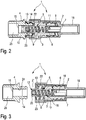
- the fluid connector 1 is by means of a relative screwing movement between the first thread 8 and the second thread 11 or between the first body 2 and the second body 3 between an open position ( Fig. 2 ) and a closed position can be transferred ( Fig. 3 ).
- the lumen 9 and the pipe section 5 interact to form a sealing connection 12 that seals the outlet 10 in a fluid-tight manner.
- the outlet 10 is released in the open position and connected to the inlet 7 in a fluid-conducting manner, for which purpose the sealing connection 12 between the lumen 9 and the tube section 5 is canceled.
- the second body 3 also has a third thread 13, which is oriented coaxially to the first thread 8 and to the second thread 11.
- the third thread 13 is designed in the opposite direction to the first thread 8 and to the second thread 11.
- the first thread 8 and the second thread 11 are each designed as a left-hand thread
- the third thread 13 is in the present case designed as a right-hand thread running in opposite directions.
- this is not mandatory.
- the third thread 13 can be designed as a left-hand thread, wherein the first thread 8 and the second thread 11 can accordingly be designed as a right-hand thread.
- the closure cap 4 In which based on the Fig. 1 and 2 In the apparent state - which can also be referred to as the delivery state - the closure cap 4 is detachably screwed to the second body 3.
- the closure cap 4 has a fourth thread 14 which is complementary is designed to the third thread 13.
- the fluid connector 1 takes in the delivery state ( Fig. 1 , 2 ) the open position, wherein the outlet 10 is closed by means of the cap 4 to be air-permeable and liquid-tight.
- the closure cap 4 in the present case has a semipermeable membrane 15, but this is not mandatory.
- a semipermeable membrane 15 in an embodiment not shown, in particular a porous filter section or a porous filter element can be provided.
- the fluid connector 1 in the based on the Fig. 1 and 2 apparent delivery state starting from the inlet 7 in the direction of the outlet 10 filled with an unspecified medical liquid.
- the inlet side of the fluid connector 1 is connected in a fluid-conducting manner to a hose section of the fluid line system, which will in turn be connected to an infusion container containing the medical liquid, in a manner which will be described in more detail.
- the medical liquid passes through the inlet 7 into the pipe section 5 and thus into the fluid channel 6.
- the medical liquid continues from the fluid channel 6 through the outlet 10 to the semipermeable membrane 15
- the medical liquid is retained by the semipermeable membrane 15, whereas any air bubbles can be flushed out of the fluid connector 1 - and the fluid line system connected to it - through the semipermeable membrane 15.
- the closure cap 4 can be removed from the second body 3 in a screw-movable manner. Due to the present design of the third thread 13 and the fourth thread 14, the closure cap 4 is rotated in the present case counterclockwise relative to the first body 2 and the second body 3 in the circumferential direction. This also has the effect that the first thread 8 and the second thread 11 are screwed against one another, as a result of which the second body 3 is displaced in the axial direction A relative to the first body 2. Due to this displacement, the fluid connector 1 is transferred from the open position to the closed position ( Fig. 3 ) and the sealing connection 12 is formed between the lumen 9 and the pipe section 5.
- the fluid connector 1 then takes the based Fig. 3 an apparent configuration in which the closure cap 4 is detached from the second body 3 and the sealing connection 12 is formed or the closed position is assumed.
- the first body 2 has a hose connector 16 which is set up for fluid-conducting connection to a hose section (not shown in the drawing) of the fluid line system.
- a hose section (not shown in the drawing) of the fluid line system.
- the hose section is inserted into the hose connector 16 in the axial direction A.
- the hose connector 16 opens at one end into the inlet 7 of the fluid channel 6.
- the first body 2 in the present case has a first collar section 17 which extends in the axial direction A and surrounds the tube section 5 in the circumferential direction.
- the first collar section 17 is spaced outwardly from the tube section 5 in the radial direction.
- an unspecified receiving space is formed between the pipe section 5 and the collar section 17, in which the second body 3 can be screwed and can be linearly displaced in the axial direction A.
- the collar section 17 has a circular cylindrical outer contour 18 which is stepped several times in the axial direction A.
- the first thread 8 is formed on the collar section 17 and is arranged on an end region of the pipe section 5 facing the hose connector 16.
- the first thread is in the present case in the form of an internal thread 8 and the second thread is accordingly in the present case in the form of an external thread 11, but this is not mandatory.
- the first thread can instead be designed in the form of an external thread and the second thread in the form of an internal thread complementary thereto.
- the pipe section 5, which extends longitudinally in the axial direction A, has a spring section 19 in the present case.
- the spring section 19 is designed to be elastically movable in the axial direction A.
- the spring section 19 is used to elastically pre-tension the sealing connection 12.
- the spring section 19 is accordingly in the closed position ( Fig. 3 ) elastically compressed under the action of the second body 3. In the open position ( Fig. 2 ) In contrast, the spring section 19 is completely expanded in the axial direction A.
- the spring section is designed in the form of a helical spring 19, but this is not mandatory.
- the spring section can be designed, for example, in the form of a bellows-like element or by a correspondingly thin-walled design of the pipe section 5.
- the lumen 9 of the second body 3 engages around the pipe section 5 in a fluid-tight manner in the closed position.
- an unspecified inner contour of the lumen 9 is matched to an unspecified outer contour of the pipe section 5.
- the inner contour of the lumen 9 has an essentially circular-cylindrical basic shape and is tapered at one end in the area of the sealing connection 12 in the radial direction.
- This tapering of the lumen 9 forms a type of conical seat 20 which, in the closed position, interacts in a fluid-tight manner with an end 21 of the pipe section 5 facing away from the inlet 7.
- the front end 21 accordingly has a conical shape that is complementary to the conical seat 20.
- the conical seat 20 and the front end 21 are displaced relative to one another in the axial direction A, so that the sealing connection 12 is canceled and the outlet 10 is released.
- the outlet 10 is connected to the fluid channel 6 and the inlet 7 in a fluid-conducting manner.
- the second body 3 in the present case has a second collar section 22.
- the second collar portion 22 extends in the axial direction A and surrounds the lumen 9 in the circumferential direction at least in sections.
- the second collar section 22 is arranged on an end of the second body 3 facing away from the second thread 11.
- the third thread 13 is formed on the second collar section 22.
- the third thread is in the form of an internal thread 13 and the fourth thread is accordingly in the form of an external thread 14 complementary thereto.
- the third thread can instead be designed in the form of an external thread and the fourth thread in the form of an internal thread.
- the second body 3 in the present case has a male Luer cone 23 which is assigned to the outlet 10.
- the Luer cone 23 extends coaxially to the lumen 9 and thus also coaxially to the tube section 5, the lumen 9 extending in sections in the axial direction A through the Luer cone 23.
- the second collar section 22 surrounds the Luer cone 23 in the circumferential direction and is oriented coaxially to it.
- the male Luer cone 23 and the third thread 13 form a male Luer lock connection 23, 13.
- the fourth thread is arranged in the form of an external thread 14 on a front end of the closure cap 4 facing the second body 3.
- the closure cap 4 in the present case has a female Luer cone 24 which is oriented coaxially to the fourth thread 14 and is provided for the fluid-tight connection with the male Luer cone 23.
- the fourth thread 14 and the female Luer cone 24 form a female Luer lock connection 14, 24 Fig. 1 and 2
- the female Luer lock connector 14, 24 and the male Luer lock connector 13, 23 are assembled in a basically known manner.
- the semipermeable membrane 15 is designed in the form of a circular disk and is arranged in a cylindrical recess 25 of the closure cap 4.
- the cylindrical recess 25 is enlarged in diameter compared to the female Luer cone 24 and is connected to it in an air-permeable and liquid-tight manner by means of the semipermeable membrane 15.
- the fluid connector 1 can be connected in a fluid-conducting manner to a complementary fluid connector (not shown in the drawing).
- the complementary fluid connector has a female Luer lock connection, which can be connected in a basically known manner to the male Luer lock connection 13, 23 of the second body 3 in a fluid-tight manner.
- the complementary fluid connector is screwed clockwise to the second body 3 and the first body 2.
- the fluid-tight connection between the female Luer lock connection of the complementary fluid connector and the male Luer lock connection 13, 23 of the second body 3 is first established. After complete screwing, the second body 3 is rotated relative to the first body 2 when the complementary fluid connector is manually actuated again.
- first thread 8 and the second thread 11 cooperate in a screw-movable manner. Due to the opposing design of the first and second thread 8, 11 compared to the third and fourth thread 13, 14, the second body 3 is thereby displaced in the axial direction A with respect to the first body 2, whereby the fluid connector 1 is moved into the open position.
Landscapes
- Health & Medical Sciences (AREA)
- Heart & Thoracic Surgery (AREA)
- Pulmonology (AREA)
- Engineering & Computer Science (AREA)
- Anesthesiology (AREA)
- Biomedical Technology (AREA)
- Hematology (AREA)
- Life Sciences & Earth Sciences (AREA)
- Animal Behavior & Ethology (AREA)
- General Health & Medical Sciences (AREA)
- Public Health (AREA)
- Veterinary Medicine (AREA)
- Infusion, Injection, And Reservoir Apparatuses (AREA)
Applications Claiming Priority (1)
| Application Number | Priority Date | Filing Date | Title |
|---|---|---|---|
| DE102019204211.2A DE102019204211A1 (de) | 2019-03-27 | 2019-03-27 | Medizinischer Fluidkonnektor |
Publications (2)
| Publication Number | Publication Date |
|---|---|
| EP3714934A1 true EP3714934A1 (fr) | 2020-09-30 |
| EP3714934B1 EP3714934B1 (fr) | 2024-05-15 |
Family
ID=69784299
Family Applications (1)
| Application Number | Title | Priority Date | Filing Date |
|---|---|---|---|
| EP20162031.7A Active EP3714934B1 (fr) | 2019-03-27 | 2020-03-10 | Connecteur de fluide médical |
Country Status (5)
| Country | Link |
|---|---|
| US (1) | US11298518B2 (fr) |
| EP (1) | EP3714934B1 (fr) |
| CN (1) | CN111744103B (fr) |
| DE (1) | DE102019204211A1 (fr) |
| ES (1) | ES2987084T3 (fr) |
Cited By (1)
| Publication number | Priority date | Publication date | Assignee | Title |
|---|---|---|---|---|
| US11471659B2 (en) * | 2016-10-25 | 2022-10-18 | Gambro Lundia Ab | Connector system with a female connector and a male connector, and a system including a plurality of the connector systems |
Families Citing this family (5)
| Publication number | Priority date | Publication date | Assignee | Title |
|---|---|---|---|---|
| US20230191023A1 (en) * | 2021-12-20 | 2023-06-22 | Luminoah, Inc. | Wearable Fluid Delivery System Providing Regimen-Predictive Analytics |
| US12208230B2 (en) * | 2022-11-09 | 2025-01-28 | Carefusion 303, Inc. | Fluid connector assembly that seals flow paths when the connectors are disconnected |
| EP4598605A1 (fr) * | 2022-12-26 | 2025-08-13 | Vantive US Healthcare LLC | Récipient de fluide médical à chambre double avec capuchon de voie d'alimentation aéré et procédé associé |
| CN120265337A (zh) * | 2022-12-26 | 2025-07-04 | 万蒂夫美国医疗保健有限责任公司 | 排气的医疗流体供应管线帽、组件及其灭菌方法 |
| CN120754429B (zh) * | 2025-09-11 | 2025-11-07 | 吉林大学第一医院 | 一种医用一次性三通阀的防漏液密封帽组件及其连接结构 |
Citations (3)
| Publication number | Priority date | Publication date | Assignee | Title |
|---|---|---|---|---|
| US20040172006A1 (en) * | 2003-02-28 | 2004-09-02 | Bonaldo Jean M. | Needleless Luer activated medical connector |
| EP3062868A1 (fr) * | 2013-10-28 | 2016-09-07 | Infusion Innovations, Inc. | Dispositifs, ensembles et procédés pour réguler un écoulement de fluide |
| EP3421077A1 (fr) | 2009-09-04 | 2019-01-02 | B. Braun Melsungen AG | Raccords males pouvant étre scellés de facon étanchet et sélective |
Family Cites Families (19)
| Publication number | Priority date | Publication date | Assignee | Title |
|---|---|---|---|---|
| US5032116A (en) * | 1991-01-09 | 1991-07-16 | Becton, Dickinson And Company | Flashback plug |
| AU2003252546B2 (en) * | 2002-08-09 | 2007-01-25 | E-Wha Fresenius Kabi Inc. | Cap of tube for supplying liquid |
| US7766897B2 (en) * | 2006-01-02 | 2010-08-03 | Carefusion 303, Inc. | Protective priming cap for self-sealing male Luer valve |
| ITTO20080381A1 (it) * | 2008-05-21 | 2009-11-22 | Industrie Borla Spa | Connettore valvolare per linee medicali |
| US8758307B2 (en) * | 2012-06-15 | 2014-06-24 | B. Braun Medical Inc. | Self-priming, anti-free flow valve for infusion pumps |
| US10137291B2 (en) * | 2014-01-31 | 2018-11-27 | Industrie Borla S.P.A. | Valved connector for medical lines |
| WO2015127285A1 (fr) * | 2014-02-20 | 2015-08-27 | Repro-Med Systems, Inc. | Raccord ayant un filtre |
| DE102014002650A1 (de) * | 2014-02-27 | 2015-08-27 | Fresenius Medical Care Deutschland Gmbh | Schraubverbinder für medizinische Schlauchsysteme und medizinisches Schlauchsystem mit Schraubverbinder |
| WO2015145998A1 (fr) * | 2014-03-28 | 2015-10-01 | テルモ株式会社 | Raccord médical |
| JP6373503B2 (ja) * | 2014-09-08 | 2018-08-15 | ネオメッド, インクNeomed, Inc. | 薬液導管のためのベントコネクタ |
| MX368388B (es) * | 2015-01-21 | 2019-10-01 | Borla Ind | Conectador de luer macho con valvula. |
| WO2017087400A1 (fr) * | 2015-11-16 | 2017-05-26 | Catheter Connections, Inc. | Capuchon de désinfection pour luer mâles |
| GB201608603D0 (en) * | 2016-05-16 | 2016-06-29 | Medical Device Creations Ltd | Improved fluid line connector device |
| DE112017003895T5 (de) * | 2016-08-02 | 2019-04-18 | Fastest, Inc. | Fluid Konnektor mit Halt an Innengewinde |
| US11471659B2 (en) * | 2016-10-25 | 2022-10-18 | Gambro Lundia Ab | Connector system with a female connector and a male connector, and a system including a plurality of the connector systems |
| CN109996573B (zh) * | 2016-11-29 | 2021-09-07 | 甘布罗伦迪亚股份公司 | 连接器结构、用于体外血液处理的系统和用于灌注血液处理单元的流体腔室的方法 |
| JP6564801B2 (ja) * | 2017-03-22 | 2019-08-21 | 日機装株式会社 | 医療用接続具 |
| DE102017210795A1 (de) * | 2017-06-27 | 2018-12-27 | B. Braun Melsungen Ag | Medizinische Fluidverbindungsvorrichtung |
| CN108744265B (zh) * | 2018-05-24 | 2024-01-09 | 深圳市迈威生物科技有限公司 | 密闭式正压接头 |
-
2019
- 2019-03-27 DE DE102019204211.2A patent/DE102019204211A1/de active Pending
-
2020
- 2020-03-10 EP EP20162031.7A patent/EP3714934B1/fr active Active
- 2020-03-10 ES ES20162031T patent/ES2987084T3/es active Active
- 2020-03-25 CN CN202010218881.XA patent/CN111744103B/zh active Active
- 2020-03-26 US US16/831,065 patent/US11298518B2/en active Active
Patent Citations (3)
| Publication number | Priority date | Publication date | Assignee | Title |
|---|---|---|---|---|
| US20040172006A1 (en) * | 2003-02-28 | 2004-09-02 | Bonaldo Jean M. | Needleless Luer activated medical connector |
| EP3421077A1 (fr) | 2009-09-04 | 2019-01-02 | B. Braun Melsungen AG | Raccords males pouvant étre scellés de facon étanchet et sélective |
| EP3062868A1 (fr) * | 2013-10-28 | 2016-09-07 | Infusion Innovations, Inc. | Dispositifs, ensembles et procédés pour réguler un écoulement de fluide |
Cited By (1)
| Publication number | Priority date | Publication date | Assignee | Title |
|---|---|---|---|---|
| US11471659B2 (en) * | 2016-10-25 | 2022-10-18 | Gambro Lundia Ab | Connector system with a female connector and a male connector, and a system including a plurality of the connector systems |
Also Published As
| Publication number | Publication date |
|---|---|
| CN111744103A (zh) | 2020-10-09 |
| US11298518B2 (en) | 2022-04-12 |
| ES2987084T3 (es) | 2024-11-13 |
| CN111744103B (zh) | 2024-09-03 |
| DE102019204211A1 (de) | 2020-10-01 |
| EP3714934B1 (fr) | 2024-05-15 |
| US20200306521A1 (en) | 2020-10-01 |
Similar Documents
| Publication | Publication Date | Title |
|---|---|---|
| EP3714934B1 (fr) | Connecteur de fluide médical | |
| EP0263789B1 (fr) | Accouplement à deux pièces pour l'échange de fluides | |
| EP0198407B1 (fr) | Connecteur pour dialyse péritonéale | |
| DE3210148C2 (de) | Konnektor | |
| DE2947574C2 (de) | Schlauchkupplung für keimfrei zu haltende Leitungsverbinder | |
| DE4313636C1 (de) | Konnektorsystem zum Verbinden von Flüssigkeitsbehältern | |
| EP1845298B1 (fr) | Couplage pour éléments tubulaires | |
| EP3381488B1 (fr) | Dispositif destiné à sécuriser un appareil de perfusion | |
| DE2521930C2 (de) | Rohrverbindungsstück | |
| DE102009044319A1 (de) | Anschlusssysteme für Fluidverbindungen | |
| DE3235464A1 (de) | Schnellkuppelbare fluidweiterleitungs-verbindungseinrichtung | |
| DE1921152A1 (de) | Adapter fuer ein geschlossenes Harnabflusssystem | |
| DE2638856B2 (de) | Zerbrechliche Strömungsmittelkupplung | |
| DE3923579C2 (de) | Anschlußarmatur für Rohre, insbesondere für Kunststoffrohre | |
| WO1984001902A1 (fr) | Raccord de catheter | |
| DE102013106550A1 (de) | Luer-Lock-Verbinder mit Nuten | |
| EP0344582A1 (fr) | Raccord pour tuyaux ou circulent des fluides aggressifs | |
| EP4146366B1 (fr) | Appareil de filtration | |
| DE102015220686B4 (de) | Filtermodul | |
| EP3421075B1 (fr) | Dispositif de liaison fluidique médical | |
| DE3306204A1 (de) | Anschlussarmatur fuer einen behaelter | |
| EP2712653B1 (fr) | Raccord de fluide | |
| DE3536297A1 (de) | Schlauch und kupplung umfassende anordnung sowie schlauchkupplung hierfuer | |
| DE10217197A1 (de) | Lösbare Kupplung zur Verbindung zweier Schlauchenden einer aus wenigstens zwei Schläuchen zusammengesetzen, flüssigkeitsführenden Schlauchleitung | |
| EP2331228A1 (fr) | Dispositif de vidange |
Legal Events
| Date | Code | Title | Description |
|---|---|---|---|
| PUAI | Public reference made under article 153(3) epc to a published international application that has entered the european phase |
Free format text: ORIGINAL CODE: 0009012 |
|
| STAA | Information on the status of an ep patent application or granted ep patent |
Free format text: STATUS: THE APPLICATION HAS BEEN PUBLISHED |
|
| AK | Designated contracting states |
Kind code of ref document: A1 Designated state(s): AL AT BE BG CH CY CZ DE DK EE ES FI FR GB GR HR HU IE IS IT LI LT LU LV MC MK MT NL NO PL PT RO RS SE SI SK SM TR |
|
| AX | Request for extension of the european patent |
Extension state: BA ME |
|
| STAA | Information on the status of an ep patent application or granted ep patent |
Free format text: STATUS: REQUEST FOR EXAMINATION WAS MADE |
|
| 17P | Request for examination filed |
Effective date: 20210301 |
|
| RBV | Designated contracting states (corrected) |
Designated state(s): AL AT BE BG CH CY CZ DE DK EE ES FI FR GB GR HR HU IE IS IT LI LT LU LV MC MK MT NL NO PL PT RO RS SE SI SK SM TR |
|
| REG | Reference to a national code |
Ref legal event code: R079 Ref country code: DE Ref legal event code: R079 Ref document number: 502020007977 Country of ref document: DE Free format text: PREVIOUS MAIN CLASS: A61M0039100000 Ipc: A61M0039200000 |
|
| GRAP | Despatch of communication of intention to grant a patent |
Free format text: ORIGINAL CODE: EPIDOSNIGR1 |
|
| STAA | Information on the status of an ep patent application or granted ep patent |
Free format text: STATUS: GRANT OF PATENT IS INTENDED |
|
| RIC1 | Information provided on ipc code assigned before grant |
Ipc: A61M 39/20 20060101AFI20231127BHEP |
|
| INTG | Intention to grant announced |
Effective date: 20231220 |
|
| GRAS | Grant fee paid |
Free format text: ORIGINAL CODE: EPIDOSNIGR3 |
|
| GRAA | (expected) grant |
Free format text: ORIGINAL CODE: 0009210 |
|
| STAA | Information on the status of an ep patent application or granted ep patent |
Free format text: STATUS: THE PATENT HAS BEEN GRANTED |
|
| AK | Designated contracting states |
Kind code of ref document: B1 Designated state(s): AL AT BE BG CH CY CZ DE DK EE ES FI FR GB GR HR HU IE IS IT LI LT LU LV MC MK MT NL NO PL PT RO RS SE SI SK SM TR |
|
| REG | Reference to a national code |
Ref country code: CH Ref legal event code: EP |
|
| REG | Reference to a national code |
Ref country code: DE Ref legal event code: R096 Ref document number: 502020007977 Country of ref document: DE |
|
| REG | Reference to a national code |
Ref country code: IE Ref legal event code: FG4D Free format text: LANGUAGE OF EP DOCUMENT: GERMAN |
|
| P01 | Opt-out of the competence of the unified patent court (upc) registered |
Effective date: 20240523 |
|
| REG | Reference to a national code |
Ref country code: SE Ref legal event code: TRGR |
|
| REG | Reference to a national code |
Ref country code: LT Ref legal event code: MG9D |
|
| REG | Reference to a national code |
Ref country code: NL Ref legal event code: MP Effective date: 20240515 |
|
| PG25 | Lapsed in a contracting state [announced via postgrant information from national office to epo] |
Ref country code: IS Free format text: LAPSE BECAUSE OF FAILURE TO SUBMIT A TRANSLATION OF THE DESCRIPTION OR TO PAY THE FEE WITHIN THE PRESCRIBED TIME-LIMIT Effective date: 20240915 |
|
| PG25 | Lapsed in a contracting state [announced via postgrant information from national office to epo] |
Ref country code: BG Free format text: LAPSE BECAUSE OF FAILURE TO SUBMIT A TRANSLATION OF THE DESCRIPTION OR TO PAY THE FEE WITHIN THE PRESCRIBED TIME-LIMIT Effective date: 20240515 |
|
| PG25 | Lapsed in a contracting state [announced via postgrant information from national office to epo] |
Ref country code: FI Free format text: LAPSE BECAUSE OF FAILURE TO SUBMIT A TRANSLATION OF THE DESCRIPTION OR TO PAY THE FEE WITHIN THE PRESCRIBED TIME-LIMIT Effective date: 20240515 Ref country code: HR Free format text: LAPSE BECAUSE OF FAILURE TO SUBMIT A TRANSLATION OF THE DESCRIPTION OR TO PAY THE FEE WITHIN THE PRESCRIBED TIME-LIMIT Effective date: 20240515 |
|
| PG25 | Lapsed in a contracting state [announced via postgrant information from national office to epo] |
Ref country code: GR Free format text: LAPSE BECAUSE OF FAILURE TO SUBMIT A TRANSLATION OF THE DESCRIPTION OR TO PAY THE FEE WITHIN THE PRESCRIBED TIME-LIMIT Effective date: 20240816 |
|
| PG25 | Lapsed in a contracting state [announced via postgrant information from national office to epo] |
Ref country code: PT Free format text: LAPSE BECAUSE OF FAILURE TO SUBMIT A TRANSLATION OF THE DESCRIPTION OR TO PAY THE FEE WITHIN THE PRESCRIBED TIME-LIMIT Effective date: 20240916 |
|
| PG25 | Lapsed in a contracting state [announced via postgrant information from national office to epo] |
Ref country code: NL Free format text: LAPSE BECAUSE OF FAILURE TO SUBMIT A TRANSLATION OF THE DESCRIPTION OR TO PAY THE FEE WITHIN THE PRESCRIBED TIME-LIMIT Effective date: 20240515 |
|
| PG25 | Lapsed in a contracting state [announced via postgrant information from national office to epo] |
Ref country code: PL Free format text: LAPSE BECAUSE OF FAILURE TO SUBMIT A TRANSLATION OF THE DESCRIPTION OR TO PAY THE FEE WITHIN THE PRESCRIBED TIME-LIMIT Effective date: 20240515 |
|
| PG25 | Lapsed in a contracting state [announced via postgrant information from national office to epo] |
Ref country code: LV Free format text: LAPSE BECAUSE OF FAILURE TO SUBMIT A TRANSLATION OF THE DESCRIPTION OR TO PAY THE FEE WITHIN THE PRESCRIBED TIME-LIMIT Effective date: 20240515 |
|
| PG25 | Lapsed in a contracting state [announced via postgrant information from national office to epo] |
Ref country code: PT Free format text: LAPSE BECAUSE OF FAILURE TO SUBMIT A TRANSLATION OF THE DESCRIPTION OR TO PAY THE FEE WITHIN THE PRESCRIBED TIME-LIMIT Effective date: 20240916 Ref country code: PL Free format text: LAPSE BECAUSE OF FAILURE TO SUBMIT A TRANSLATION OF THE DESCRIPTION OR TO PAY THE FEE WITHIN THE PRESCRIBED TIME-LIMIT Effective date: 20240515 Ref country code: NO Free format text: LAPSE BECAUSE OF FAILURE TO SUBMIT A TRANSLATION OF THE DESCRIPTION OR TO PAY THE FEE WITHIN THE PRESCRIBED TIME-LIMIT Effective date: 20240815 Ref country code: NL Free format text: LAPSE BECAUSE OF FAILURE TO SUBMIT A TRANSLATION OF THE DESCRIPTION OR TO PAY THE FEE WITHIN THE PRESCRIBED TIME-LIMIT Effective date: 20240515 Ref country code: LV Free format text: LAPSE BECAUSE OF FAILURE TO SUBMIT A TRANSLATION OF THE DESCRIPTION OR TO PAY THE FEE WITHIN THE PRESCRIBED TIME-LIMIT Effective date: 20240515 Ref country code: IS Free format text: LAPSE BECAUSE OF FAILURE TO SUBMIT A TRANSLATION OF THE DESCRIPTION OR TO PAY THE FEE WITHIN THE PRESCRIBED TIME-LIMIT Effective date: 20240915 Ref country code: HR Free format text: LAPSE BECAUSE OF FAILURE TO SUBMIT A TRANSLATION OF THE DESCRIPTION OR TO PAY THE FEE WITHIN THE PRESCRIBED TIME-LIMIT Effective date: 20240515 Ref country code: GR Free format text: LAPSE BECAUSE OF FAILURE TO SUBMIT A TRANSLATION OF THE DESCRIPTION OR TO PAY THE FEE WITHIN THE PRESCRIBED TIME-LIMIT Effective date: 20240816 Ref country code: FI Free format text: LAPSE BECAUSE OF FAILURE TO SUBMIT A TRANSLATION OF THE DESCRIPTION OR TO PAY THE FEE WITHIN THE PRESCRIBED TIME-LIMIT Effective date: 20240515 Ref country code: BG Free format text: LAPSE BECAUSE OF FAILURE TO SUBMIT A TRANSLATION OF THE DESCRIPTION OR TO PAY THE FEE WITHIN THE PRESCRIBED TIME-LIMIT Effective date: 20240515 Ref country code: RS Free format text: LAPSE BECAUSE OF FAILURE TO SUBMIT A TRANSLATION OF THE DESCRIPTION OR TO PAY THE FEE WITHIN THE PRESCRIBED TIME-LIMIT Effective date: 20240815 |
|
| REG | Reference to a national code |
Ref country code: ES Ref legal event code: FG2A Ref document number: 2987084 Country of ref document: ES Kind code of ref document: T3 Effective date: 20241113 |
|
| PG25 | Lapsed in a contracting state [announced via postgrant information from national office to epo] |
Ref country code: DK Free format text: LAPSE BECAUSE OF FAILURE TO SUBMIT A TRANSLATION OF THE DESCRIPTION OR TO PAY THE FEE WITHIN THE PRESCRIBED TIME-LIMIT Effective date: 20240515 |
|
| PG25 | Lapsed in a contracting state [announced via postgrant information from national office to epo] |
Ref country code: EE Free format text: LAPSE BECAUSE OF FAILURE TO SUBMIT A TRANSLATION OF THE DESCRIPTION OR TO PAY THE FEE WITHIN THE PRESCRIBED TIME-LIMIT Effective date: 20240515 |
|
| PG25 | Lapsed in a contracting state [announced via postgrant information from national office to epo] |
Ref country code: CZ Free format text: LAPSE BECAUSE OF FAILURE TO SUBMIT A TRANSLATION OF THE DESCRIPTION OR TO PAY THE FEE WITHIN THE PRESCRIBED TIME-LIMIT Effective date: 20240515 |
|
| PG25 | Lapsed in a contracting state [announced via postgrant information from national office to epo] |
Ref country code: RO Free format text: LAPSE BECAUSE OF FAILURE TO SUBMIT A TRANSLATION OF THE DESCRIPTION OR TO PAY THE FEE WITHIN THE PRESCRIBED TIME-LIMIT Effective date: 20240515 Ref country code: SK Free format text: LAPSE BECAUSE OF FAILURE TO SUBMIT A TRANSLATION OF THE DESCRIPTION OR TO PAY THE FEE WITHIN THE PRESCRIBED TIME-LIMIT Effective date: 20240515 |
|
| PG25 | Lapsed in a contracting state [announced via postgrant information from national office to epo] |
Ref country code: SM Free format text: LAPSE BECAUSE OF FAILURE TO SUBMIT A TRANSLATION OF THE DESCRIPTION OR TO PAY THE FEE WITHIN THE PRESCRIBED TIME-LIMIT Effective date: 20240515 |
|
| PG25 | Lapsed in a contracting state [announced via postgrant information from national office to epo] |
Ref country code: SM Free format text: LAPSE BECAUSE OF FAILURE TO SUBMIT A TRANSLATION OF THE DESCRIPTION OR TO PAY THE FEE WITHIN THE PRESCRIBED TIME-LIMIT Effective date: 20240515 Ref country code: SK Free format text: LAPSE BECAUSE OF FAILURE TO SUBMIT A TRANSLATION OF THE DESCRIPTION OR TO PAY THE FEE WITHIN THE PRESCRIBED TIME-LIMIT Effective date: 20240515 Ref country code: RO Free format text: LAPSE BECAUSE OF FAILURE TO SUBMIT A TRANSLATION OF THE DESCRIPTION OR TO PAY THE FEE WITHIN THE PRESCRIBED TIME-LIMIT Effective date: 20240515 Ref country code: EE Free format text: LAPSE BECAUSE OF FAILURE TO SUBMIT A TRANSLATION OF THE DESCRIPTION OR TO PAY THE FEE WITHIN THE PRESCRIBED TIME-LIMIT Effective date: 20240515 Ref country code: DK Free format text: LAPSE BECAUSE OF FAILURE TO SUBMIT A TRANSLATION OF THE DESCRIPTION OR TO PAY THE FEE WITHIN THE PRESCRIBED TIME-LIMIT Effective date: 20240515 Ref country code: CZ Free format text: LAPSE BECAUSE OF FAILURE TO SUBMIT A TRANSLATION OF THE DESCRIPTION OR TO PAY THE FEE WITHIN THE PRESCRIBED TIME-LIMIT Effective date: 20240515 |
|
| REG | Reference to a national code |
Ref country code: DE Ref legal event code: R097 Ref document number: 502020007977 Country of ref document: DE |
|
| PLBE | No opposition filed within time limit |
Free format text: ORIGINAL CODE: 0009261 |
|
| STAA | Information on the status of an ep patent application or granted ep patent |
Free format text: STATUS: NO OPPOSITION FILED WITHIN TIME LIMIT |
|
| 26N | No opposition filed |
Effective date: 20250218 |
|
| PG25 | Lapsed in a contracting state [announced via postgrant information from national office to epo] |
Ref country code: SI Free format text: LAPSE BECAUSE OF FAILURE TO SUBMIT A TRANSLATION OF THE DESCRIPTION OR TO PAY THE FEE WITHIN THE PRESCRIBED TIME-LIMIT Effective date: 20240515 |
|
| PGFP | Annual fee paid to national office [announced via postgrant information from national office to epo] |
Ref country code: ES Payment date: 20250416 Year of fee payment: 6 |
|
| PGFP | Annual fee paid to national office [announced via postgrant information from national office to epo] |
Ref country code: IT Payment date: 20250331 Year of fee payment: 6 |
|
| PG25 | Lapsed in a contracting state [announced via postgrant information from national office to epo] |
Ref country code: MC Free format text: LAPSE BECAUSE OF FAILURE TO SUBMIT A TRANSLATION OF THE DESCRIPTION OR TO PAY THE FEE WITHIN THE PRESCRIBED TIME-LIMIT Effective date: 20240515 |
|
| REG | Reference to a national code |
Ref country code: CH Ref legal event code: H13 Free format text: ST27 STATUS EVENT CODE: U-0-0-H10-H13 (AS PROVIDED BY THE NATIONAL OFFICE) Effective date: 20251023 |
|
| PG25 | Lapsed in a contracting state [announced via postgrant information from national office to epo] |
Ref country code: LU Free format text: LAPSE BECAUSE OF NON-PAYMENT OF DUE FEES Effective date: 20250310 |
|
| REG | Reference to a national code |
Ref country code: BE Ref legal event code: MM Effective date: 20250331 |
|
| PG25 | Lapsed in a contracting state [announced via postgrant information from national office to epo] |
Ref country code: BE Free format text: LAPSE BECAUSE OF NON-PAYMENT OF DUE FEES Effective date: 20250331 |
|
| PG25 | Lapsed in a contracting state [announced via postgrant information from national office to epo] |
Ref country code: CH Free format text: LAPSE BECAUSE OF NON-PAYMENT OF DUE FEES Effective date: 20250331 |
|
| PG25 | Lapsed in a contracting state [announced via postgrant information from national office to epo] |
Ref country code: IE Free format text: LAPSE BECAUSE OF NON-PAYMENT OF DUE FEES Effective date: 20250310 |
|
| PGFP | Annual fee paid to national office [announced via postgrant information from national office to epo] |
Ref country code: SE Payment date: 20260323 Year of fee payment: 7 |
|
| PGFP | Annual fee paid to national office [announced via postgrant information from national office to epo] |
Ref country code: GB Payment date: 20260324 Year of fee payment: 7 |
|
| PGFP | Annual fee paid to national office [announced via postgrant information from national office to epo] |
Ref country code: DE Payment date: 20260320 Year of fee payment: 7 |
|
| PGFP | Annual fee paid to national office [announced via postgrant information from national office to epo] |
Ref country code: FR Payment date: 20260324 Year of fee payment: 7 |