EP3715214B1 - Motorsteuergerät - Google Patents
Motorsteuergerät Download PDFInfo
- Publication number
- EP3715214B1 EP3715214B1 EP19218480.2A EP19218480A EP3715214B1 EP 3715214 B1 EP3715214 B1 EP 3715214B1 EP 19218480 A EP19218480 A EP 19218480A EP 3715214 B1 EP3715214 B1 EP 3715214B1
- Authority
- EP
- European Patent Office
- Prior art keywords
- torque
- winding group
- processors
- target
- motor
- Prior art date
- Legal status (The legal status is an assumption and is not a legal conclusion. Google has not performed a legal analysis and makes no representation as to the accuracy of the status listed.)
- Active
Links
Images



Classifications
-
- B—PERFORMING OPERATIONS; TRANSPORTING
- B62—LAND VEHICLES FOR TRAVELLING OTHERWISE THAN ON RAILS
- B62D—MOTOR VEHICLES; TRAILERS
- B62D5/00—Power-assisted or power-driven steering
- B62D5/04—Power-assisted or power-driven steering electrical, e.g. using an electric servo-motor connected to, or forming part of, the steering gear
- B62D5/0403—Power-assisted or power-driven steering electrical, e.g. using an electric servo-motor connected to, or forming part of, the steering gear characterised by constructional features, e.g. common housing for motor and gear box
-
- B—PERFORMING OPERATIONS; TRANSPORTING
- B62—LAND VEHICLES FOR TRAVELLING OTHERWISE THAN ON RAILS
- B62D—MOTOR VEHICLES; TRAILERS
- B62D5/00—Power-assisted or power-driven steering
- B62D5/04—Power-assisted or power-driven steering electrical, e.g. using an electric servo-motor connected to, or forming part of, the steering gear
- B62D5/0457—Power-assisted or power-driven steering electrical, e.g. using an electric servo-motor connected to, or forming part of, the steering gear characterised by control features of the drive means as such
- B62D5/046—Controlling the motor
- B62D5/0463—Controlling the motor calculating assisting torque from the motor based on driver input
-
- B—PERFORMING OPERATIONS; TRANSPORTING
- B62—LAND VEHICLES FOR TRAVELLING OTHERWISE THAN ON RAILS
- B62D—MOTOR VEHICLES; TRAILERS
- B62D5/00—Power-assisted or power-driven steering
- B62D5/04—Power-assisted or power-driven steering electrical, e.g. using an electric servo-motor connected to, or forming part of, the steering gear
- B62D5/0457—Power-assisted or power-driven steering electrical, e.g. using an electric servo-motor connected to, or forming part of, the steering gear characterised by control features of the drive means as such
- B62D5/046—Controlling the motor
-
- B—PERFORMING OPERATIONS; TRANSPORTING
- B62—LAND VEHICLES FOR TRAVELLING OTHERWISE THAN ON RAILS
- B62D—MOTOR VEHICLES; TRAILERS
- B62D5/00—Power-assisted or power-driven steering
- B62D5/04—Power-assisted or power-driven steering electrical, e.g. using an electric servo-motor connected to, or forming part of, the steering gear
- B62D5/0457—Power-assisted or power-driven steering electrical, e.g. using an electric servo-motor connected to, or forming part of, the steering gear characterised by control features of the drive means as such
- B62D5/0481—Power-assisted or power-driven steering electrical, e.g. using an electric servo-motor connected to, or forming part of, the steering gear characterised by control features of the drive means as such monitoring the steering system, e.g. failures
-
- B—PERFORMING OPERATIONS; TRANSPORTING
- B62—LAND VEHICLES FOR TRAVELLING OTHERWISE THAN ON RAILS
- B62D—MOTOR VEHICLES; TRAILERS
- B62D5/00—Power-assisted or power-driven steering
- B62D5/04—Power-assisted or power-driven steering electrical, e.g. using an electric servo-motor connected to, or forming part of, the steering gear
- B62D5/0457—Power-assisted or power-driven steering electrical, e.g. using an electric servo-motor connected to, or forming part of, the steering gear characterised by control features of the drive means as such
- B62D5/0481—Power-assisted or power-driven steering electrical, e.g. using an electric servo-motor connected to, or forming part of, the steering gear characterised by control features of the drive means as such monitoring the steering system, e.g. failures
- B62D5/0484—Power-assisted or power-driven steering electrical, e.g. using an electric servo-motor connected to, or forming part of, the steering gear characterised by control features of the drive means as such monitoring the steering system, e.g. failures for reaction to failures, e.g. limp home
-
- B—PERFORMING OPERATIONS; TRANSPORTING
- B62—LAND VEHICLES FOR TRAVELLING OTHERWISE THAN ON RAILS
- B62D—MOTOR VEHICLES; TRAILERS
- B62D5/00—Power-assisted or power-driven steering
- B62D5/04—Power-assisted or power-driven steering electrical, e.g. using an electric servo-motor connected to, or forming part of, the steering gear
- B62D5/0457—Power-assisted or power-driven steering electrical, e.g. using an electric servo-motor connected to, or forming part of, the steering gear characterised by control features of the drive means as such
- B62D5/0481—Power-assisted or power-driven steering electrical, e.g. using an electric servo-motor connected to, or forming part of, the steering gear characterised by control features of the drive means as such monitoring the steering system, e.g. failures
- B62D5/0487—Power-assisted or power-driven steering electrical, e.g. using an electric servo-motor connected to, or forming part of, the steering gear characterised by control features of the drive means as such monitoring the steering system, e.g. failures detecting motor faults
-
- B—PERFORMING OPERATIONS; TRANSPORTING
- B62—LAND VEHICLES FOR TRAVELLING OTHERWISE THAN ON RAILS
- B62D—MOTOR VEHICLES; TRAILERS
- B62D5/00—Power-assisted or power-driven steering
- B62D5/04—Power-assisted or power-driven steering electrical, e.g. using an electric servo-motor connected to, or forming part of, the steering gear
- B62D5/0457—Power-assisted or power-driven steering electrical, e.g. using an electric servo-motor connected to, or forming part of, the steering gear characterised by control features of the drive means as such
- B62D5/0481—Power-assisted or power-driven steering electrical, e.g. using an electric servo-motor connected to, or forming part of, the steering gear characterised by control features of the drive means as such monitoring the steering system, e.g. failures
- B62D5/0493—Power-assisted or power-driven steering electrical, e.g. using an electric servo-motor connected to, or forming part of, the steering gear characterised by control features of the drive means as such monitoring the steering system, e.g. failures detecting processor errors, e.g. plausibility of steering direction
-
- B—PERFORMING OPERATIONS; TRANSPORTING
- B62—LAND VEHICLES FOR TRAVELLING OTHERWISE THAN ON RAILS
- B62D—MOTOR VEHICLES; TRAILERS
- B62D6/00—Arrangements for automatically controlling steering depending on driving conditions sensed and responded to, e.g. control circuits
-
- H—ELECTRICITY
- H02—GENERATION; CONVERSION OR DISTRIBUTION OF ELECTRIC POWER
- H02P—CONTROL OR REGULATION OF ELECTRIC MOTORS, ELECTRIC GENERATORS OR DYNAMO-ELECTRIC CONVERTERS; CONTROLLING TRANSFORMERS, REACTORS OR CHOKE COILS
- H02P25/00—Arrangements or methods for the control of AC motors characterised by the kind of AC motor or by structural details
- H02P25/16—Arrangements or methods for the control of AC motors characterised by the kind of AC motor or by structural details characterised by the circuit arrangement or by the kind of wiring
- H02P25/22—Multiple windings; Windings for more than three phases
-
- H—ELECTRICITY
- H02—GENERATION; CONVERSION OR DISTRIBUTION OF ELECTRIC POWER
- H02P—CONTROL OR REGULATION OF ELECTRIC MOTORS, ELECTRIC GENERATORS OR DYNAMO-ELECTRIC CONVERTERS; CONTROLLING TRANSFORMERS, REACTORS OR CHOKE COILS
- H02P29/00—Arrangements for regulating or controlling electric motors, appropriate for both AC and DC motors
- H02P29/02—Providing protection against overload without automatic interruption of supply
- H02P29/024—Detecting a fault condition, e.g. short circuit, locked rotor, open circuit or loss of load
- H02P29/028—Detecting a fault condition, e.g. short circuit, locked rotor, open circuit or loss of load the motor continuing operation despite the fault condition, e.g. eliminating, compensating for or remedying the fault
-
- H—ELECTRICITY
- H02—GENERATION; CONVERSION OR DISTRIBUTION OF ELECTRIC POWER
- H02P—CONTROL OR REGULATION OF ELECTRIC MOTORS, ELECTRIC GENERATORS OR DYNAMO-ELECTRIC CONVERTERS; CONTROLLING TRANSFORMERS, REACTORS OR CHOKE COILS
- H02P6/00—Arrangements for controlling synchronous motors or other dynamo-electric motors using electronic commutation dependent on the rotor position; Electronic commutators therefor
- H02P6/08—Arrangements for controlling the speed or torque of a single motor
Definitions
- the present invention relates to a motor controller.
- an electric power steering system configured to apply, to a steering mechanism, an assist torque for assisting a driver's steering operation by using a motor as a drive source.
- the EPS may use a motor including winding groups having a plurality of separate energization systems for the purpose of achieving redundancy or the like.
- JP 2017-229156 A discloses a motor controller configured to control this type of motor.
- the motor controller includes two microcomputers and two drive circuits corresponding to winding groups of two systems.
- the microcomputers control the corresponding drive circuits based on a steering torque input to a steering mechanism to independently control driving electric power to be supplied to the winding groups of two systems.
- the entire motor outputs, as an assist torque, the total of torques that are based on magnetic fluxes generated in the winding groups of the respective systems.
- DE 10 2015 212 585 A1 discloses a motor controller configured to control a motor including a plurality of winding groups.
- the motor is provided with a plurality of energization systems. Each of the winding groups is included in a corresponding one of the energization systems.
- the motor controller includes a plurality of processors. Each of the processors is configured to independently control supply of driving electric power to each of the winding groups in the corresponding one of the energization systems. Each of the processors are configured to calculate respective control signals based on target individual torques which is split for each of the winding groups in the corresponding one of the energization systems from a target overall torque to be generated in the motor.
- Each of the processors include drive circuits configured to supply the driving electric power to each of the winding groups in the corresponding one of the energization systems based on the control signals.
- Each of the processors are configured such that, when an abnormality occurs in one of the energization systems, the processor, controlling supply of driving electric power to the winding group in the corresponding one of the energization systems in which the abnormality does not occur, out of the plurality of processors controls supply of the driving electric power such that the winding group generates a torque compensating for the braking torque generated by the counter electromotive voltage, which is generated in the failure system.
- WO 2017/158681 A1 discloses an electric motor control system and an electric power steering apparatus in which torque of the electric motor can be increased for ensuring of steering performance even at the time of abnormality occurrence.
- the controller of the system is provided with 2 sets of control systems.
- a rated torque is set as an upper limit of a torque that can be output in the winding group of each energization system.
- a target torque of each energization system is calculated by the microcomputer so that the target torque is equal to or smaller than the rated torque preset depending on, for example, specifications of the motor or the drive circuit.
- the rated torque is smaller than a limit torque determined depending on the structure of the motor as a limit of the torque that can be output in the winding group of each energization system.
- the rated torque is set to such a torque that a temperature increase caused by energization can be permitted and a sufficient assist torque can continuously be applied when a necessary assist torque increases as in a case of stationary steering or the like.
- This problem may arise not only in the EPS, but also in a steer-by-wire type steering system in which power transmission between a steering portion and a steered portion is separated.
- the problem may arise not only in the case where the motor configured to apply the assist torque is controlled for the EPS, but also in a case where a motor configured to apply a steering operation torque for turning steered wheels is controlled for the steer-by-wire type steering system.
- the present invention provides a motor controller as claimed in claim 1 in which deficiency of a torque to be applied from a motor can be suppressed in the event of an abnormality.
- a motor controller is configured to control a motor including a plurality of winding groups.
- the motor is provided with a plurality of energization systems.
- Each of the winding groups is included in a corresponding one of the energization systems.
- the motor controller includes a plurality of processors.
- Each of the processors is configured to independently control supply of driving electric power to each of the winding groups in the corresponding one of the energization systems.
- Each of the processors are configured to calculate respective control signals based on target individual torques which is split for each of the winding groups in the corresponding one of the energization systems from a target overall torque to be generated in the motor.
- Each of the processors include drive circuits configured to supply the driving electric power to each of the winding groups in the corresponding one of the energization systems based on the control signals.
- Each of the processors are configured to calculate the target individual torques so that each of the target individual torques is equal to or smaller than an individual rated torque set to be smaller than an individual limit torque determined depending on a structure of the motor as a limit of a torque to be output in each of the winding groups in the corresponding one of the energization systems.
- Each of the processors are configured such that, when an abnormality occurs in which a torque to be generated in one of the winding groups in the corresponding one of the energization systems is smaller than the individual rated torque and the target overall torque is larger than when a total of the individual rated torque for the winding group in the corresponding one of the energization systems in which the abnormality does not occur, the processor, controlling supply of driving electric power to the winding group in the corresponding one of the energization systems in which the abnormality does not occur, out of the plurality of processors controls supply of the driving electric power such that the winding group generate a torque larger than the individual rated torque.
- the winding group of each energization system can generate a torque larger than the individual rated torque from the viewpoint of the structure of the motor.
- the winding group of this energization system when the abnormality occurs in which the torque to be generated in one of the winding groups in the corresponding one of the energization systems is smaller than the individual rated torque and when the target overall torque is larger than the individual rated torque for the winding group in the corresponding one of the energization systems in which the abnormality does not occur, the winding group of this energization system generates the torque larger than the individual rated torque. Therefore, deficiency of the torque to be applied from the motor can be suppressed for the short time until the motor or the drive circuit is overheated.
- each of the processors may be configured to detect a current abnormality including at least one of a wire disconnection and a short circuit in the energization system.
- the processors may be configured such that, when the current abnormality is detected and when the target overall torque is larger than the total of the individual rated torque for the winding group in the corresponding one of the energization systems in which the current abnormality does not occur, the processor, controlling supply of driving electric power to the winding group in the corresponding one of the energization system in which the current abnormality does not occur, out of the plurality of processors controls supply of the driving electric power such that the winding group generate a torque larger than the individual rated torque.
- the deficiency of the torque to be applied from the motor can be suppressed for the short time until the motor or the drive circuit is overheated in the event of the current abnormality in which the winding group of one of the energization systems cannot generate the torque due to, for example, a wire disconnection or a short circuit in this energization system.
- each of the processors may be configured to detect an operation abnormality of the processor configured to controls supply of driving electric power to the winding group in the corresponding one of the other energization system.
- the processors may be configured such that, when the operation abnormality is detected and when the target overall torque is larger than the total of the individual rated torque for the winding group in the corresponding one of the energization systems in which the operation abnormality does not occur, the processor, controlling supply of driving electric power to the winding group in the corresponding one of the energization systems in which the operation abnormality does not occur, out of the plurality of processors controls supply of the driving electric power such that the winding group generate a torque larger than the individual rated torque.
- the deficiency of the torque to be applied from the motor can be suppressed for the short time until the motor or the drive circuit is overheated in the event of the operation abnormality in which the winding group corresponding to one of processors cannot generate the torque due to, for example, a halt of the processor.
- the processors may be connected to individual external power supplies.
- the processors may be configured to calculate individual restriction torques for restricting the target individual torques to the individual rated torques or smaller based on power supply voltages of the external power supplies.
- the processors may be configured such that, when one of the winding groups in the corresponding one of the energization systems is in a restricted state in which the individual restriction torque is smaller than the individual rated torque and when the target overall torque is larger than a total of the individual rated torque of the winding group in the corresponding one of the energization systems that is not in the restricted state and the individual restriction torque of the energization system that is in the restricted state, the processor controlling supply of driving electric power to the winding group in the corresponding one of the energization systems that is not in the restricted state, out of the plurality of processors controls supply of the driving electric power such that the winding group generates a torque larger than the individual rated torque.
- the deficiency of the torque to be applied from the motor can be suppressed for the short time until the motor or the drive circuit is overheated in the restricted state in which the power supply voltage of one of the external power supplies decreases and the winding group of the energization system connected to the external power supply can only generate a torque smaller than the individual rated torque.
- the motor may be configured to generate a torque to be applied to a steering mechanism.
- the deficiency of the torque to be applied from the motor is suppressed even if the abnormality occurs, for example, while the vehicle is making a turn. Accordingly, it is possible to reduce, for example, the occurrence of a case where the traveling direction of the vehicle deviates from a target direction.
- deficiency of the torque to be applied from the motor can be suppressed in the event of an abnormality.
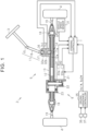
- a steering controller 1 controls a steering apparatus 2.
- the steering apparatus 2 is constructed as an electric power steering system (EPS).
- EPS electric power steering system
- the steering apparatus 2 includes a steering mechanism 5 and an actuator 6.
- the steering mechanism 5 turns steered wheels 4 based on a driver's operation for a steering wheel 3.
- the actuator 6 applies a motor torque to the steering mechanism 5 as an assist torque (assist force) for assisting a steering operation or a steering operation torque (steering operation force) for turning the steered wheels 4.
- assist torque assist force
- steering operation torque steering operation force
- the steering mechanism 5 includes a steering shaft 11, a rack shaft 12, a cylindrical rack housing 13, and a rack and pinion mechanism 14.
- the steering wheel 3 is fixed to the steering shaft 11.
- the rack shaft 12 serves as a steering operation shaft coupled to the steering shaft 11.
- the rack shaft 12 is inserted through the rack housing 13 in a reciprocable manner.
- the rack and pinion mechanism 14 converts rotation of the steering shaft 11 into reciprocating motion of the rack shaft 12.
- the steering shaft 11 is constructed by coupling a column shaft 15, an intermediate shaft 16, and a pinion shaft 17 in order from a side where the steering wheel 3 is located.
- the rack shaft 12 and the pinion shaft 17 are arranged in the rack housing 13 at a predetermined crossing angle.
- the rack and pinion mechanism 14 is constructed such that rack teeth 12a formed on the rack shaft 12 mesh with pinion teeth 17a formed on the pinion shaft 17.
- Tie rods 19 are pivotably coupled to respective ends of the rack shaft 12 via rack ends 18 formed of ball joints provided at axial ends of the rack shaft 12.
- the distal ends of the tie rods 19 are coupled to knuckles (not illustrated) to which the steered wheels 4 are attached.
- rotation of the steering shaft 11 along with the steering operation is converted into axial movement of the rack shaft 12 by the rack and pinion mechanism 14.
- the axial movement is transmitted to the knuckles via the tie rods 19.
- the steered angle of each of the steered wheels 4, that is, the traveling direction of a vehicle is changed.
- the actuator 6 includes a motor 21, a transmission mechanism 22, and a conversion mechanism 23.
- the motor 21 is a drive source.
- the transmission mechanism 22 transmits rotation of the motor 21.
- the conversion mechanism 23 converts the rotation transmitted via the transmission mechanism 22 into reciprocating motion of the rack shaft 12.
- the actuator 6 transmits the rotation of the motor 21 to the conversion mechanism 23 via the transmission mechanism 22, and converts the rotation into the reciprocating motion of the rack shaft 12 by the conversion mechanism 23, thereby applying an assist torque or a steering operation torque to the steering mechanism 5.
- a three-phase brushless motor is employed as the motor 21 of this embodiment.
- a belt mechanism is employed as the transmission mechanism 22.
- a ball screw mechanism is employed as the conversion mechanism 23.
- the steering controller 1 acquires detection results from various sensors provided on the vehicle as pieces of information (condition amounts) indicating a driver's request, a traveling condition, and a steering condition, and controls the motor 21 based on the condition amounts.
- various sensors include a vehicle speed sensor 31, torque sensors 32a and 32b, and rotation angle sensors 33a and 33b.
- the vehicle speed sensor 31 detects a vehicle speed SPD.
- the torque sensors 32a and 32b are provided on the pinion shaft 17, and detect steering torques Th1 and Th2 input to the steering mechanism 5 based on a twist of a torsion bar 34, respectively.
- the steering torques Th1 and Th2 basically take the same value when the torque sensors 32a and 32b are normal.
- the rotation angle sensors 33a and 33b detect rotation angles ⁇ 1 and ⁇ 2 of the motor 21 as relative angles within a range of 360°, respectively.
- the rotation angles ⁇ 1 and ⁇ 2 basically take the same value when the rotation angle sensors 33a and 33b are normal.
- the steering controller 1 is connected to a driving assistance controller 35 provided outside the steering controller 1.
- the driving assistance controller 35 of this embodiment executes, as driving assistance control, lane keeping assistance control for assisting the driver's steering operation so that the vehicle easily travels while keeping a traveling lane.
- the driving assistance controller 35 calculates, based on data on an image captured by a camera 36, an ideal steered angle at which the vehicle can keep traveling along the lane, and calculates driving assistance command values ⁇ p1 ⁇ and ⁇ p2 ⁇ based on a deviation between the ideal steered angle and an actual steered angle of each of the steered wheels 4.
- Each of the driving assistance command values ⁇ p1 ⁇ and ⁇ p2 ⁇ of this embodiment is a value indicating a target value of a rotation angle of the pinion shaft 17 (pinion angle ⁇ p).
- the pinion angle ⁇ p is convertible into the steered angle.
- the driving assistance controller 35 is connected to an operation switch 37 provided, for example, near a driver's seat of the vehicle and to be used for executing the driving assistance control.
- the driving assistance controller 35 executes the driving assistance control depending on whether the operation switch 37 is ON or OFF.
- the driving assistance controller 35 outputs the driving assistance command values ⁇ p1 ⁇ and ⁇ p2 ⁇ to the steering controller 1.
- the steering controller 1 supplies driving electric power to the motor 21 based on signals indicating the condition amounts input from the sensors and signals input from the driving assistance controller 35, thereby controlling actuation of the actuator 6, that is, the torque to be applied to the steering mechanism 5 so that the rack shaft 12 reciprocates.
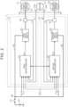
- the motor 21 includes a rotor 41, and a first winding group 42 and a second winding group 43 wound around a stator (not illustrated).
- Each of the first winding group 42 and the second winding group 43 includes coils of three phases that are U, V, and W phases.
- the first winding group 42 and the second winding group 43 have separate energization systems.
- the first winding group 42 is connected to the steering controller 1 via first connection lines 44.
- the second winding group 43 is connected to the steering controller 1 via second connection lines 45.
- FIG. 2 illustrates one collective first connection line 44 and one collective second connection line 45 for the respective phases.
- the first winding group 42 and the second winding group 43 of this embodiment are constructed to have the same specifications of the coils (wire diameters and numbers of turns of the winding).
- a first limit torque Tlim1 is equal to a second limit torque Tlim2.
- the first limit torque Tlim1 is an individual limit torque determined depending on a magnetic flux generated in the first winding group 42 and the structure of the motor 21 as typified by a magnetic flux density of the rotor 41 and a magnetic permeability of the stator.
- the second limit torque Tlim2 is an individual limit torque determined depending on a magnetic flux generated in the second winding group 43 and the structure of the motor 21.
- an overall limit torque Tlimw of the entire motor 21 is the total of the first limit torque Tlim1 and the second limit torque Tlim2.
- An overall rated torque Traw is preset in the motor 21 as a smaller torque than the overall limit torque Tlimw and as such a torque that a temperature increase caused by energization can be permitted and a sufficient torque can continuously be applied when a necessary target overall torque Tw* increases as in a case of stationary steering or the like.
- a first rated torque Tra1 is preset in the first winding group 42 as an individual rated torque smaller than the first limit torque Tlim1
- a second rated torque Tra2 is preset in the second winding group 43 as an individual rated torque smaller than the second limit torque Tlim2.
- the first rated torque Tra1 is equal to the second rated torque Tra2.
- the steering controller 1 includes a first control unit 51 and a second control unit 61.
- the first control unit 51 controls energization of the first winding group 42.
- the second control unit 61 controls energization of the second winding group 43.
- the steering controller 1 independently controls the supply of the driving electric power to the first winding group 42 and the second winding group 43 for the respective energization systems.
- Each of the first control unit 51 and the second control unit 61 is a processor including a central processing unit (CPU) and a memory (not illustrated), and executes various types of control by the CPU executing a program stored in the memory in every predetermined calculation period.
- the first control unit 51 includes a first microcomputer 52 and a first drive circuit 53.
- the first microcomputer 52 serves as a control signal output unit configured to output a first control signal Sc1.
- the first drive circuit 53 supplies the driving electric power to the first winding group 42 based on the first control signal Sc1.
- First current sensors 54 are connected to the first microcomputer 52.
- the first current sensors 54 detect actual current values I1 of currents flowing through the first connection lines 44.
- FIG. 2 illustrates one collective first current sensor 54 for the respective phases.
- the first drive circuit 53 is connected to an on-board power supply (battery) 56 via a first power supply line 55.
- the on-board power supply 56 is an external power supply mounted on the vehicle.
- the first power supply line 55 is provided with a power supply relay 57 to be turned ON or OFF in response to a signal from an activation switch of the vehicle (such as an ignition switch or a start switch).
- the first drive circuit 53 can supply the driving electric power to the first winding group 42 based on a power supply voltage of the on-board power supply 56 while the power supply relay 57 is turned ON and the first power supply line 55 is brought into conduction. Electric power of the on-board power supply 56 is supplied to the first microcomputer 52 via a power feed line (not illustrated).
- a known pulse width modulation (PWM) inverter is employed as the first drive circuit 53.
- PWM pulse width modulation
- pairs of switching elements for example, field effect transistors
- the first control signal Sc1 is a gate ON/OFF signal for defining ON/OFF states of the switching elements.
- the first drive circuit 53 turns ON or OFF the switching elements in response to the first control signal Sc1 to convert direct current (DC) power supplied from the on-board power supply 56 into three-phase alternating current (AC) power, and supplies the three-phase AC power to the first winding group 42 via the first connection lines 44.
- DC direct current
- AC alternating current
- the first control unit 51 controls a torque to be generated in the first winding group 42 through the supply of the driving electric power to the first winding group 42. If the motor 21 or the first drive circuit 53 is overheated, the first control unit 51 stops the supply of the driving electric power.
- the second control unit 61 is basically constructed similarly to the first control unit 51, and includes a second microcomputer 62 and a second drive circuit 63.
- the second microcomputer 62 serves as a control signal output unit configured to output a second control signal Sc2.
- the second drive circuit 63 supplies the driving electric power to the second winding group 43 based on the second control signal Sc2.
- Second current sensors 64 are connected to the second microcomputer 62.
- the second current sensors 64 detect actual current values I2 of currents flowing through the second connection lines 45.
- FIG. 2 illustrates one collective second current sensor 64 for the respective phases.
- the second drive circuit 63 of this embodiment is supplied with electric power from the same on-board power supply 56 as that in the case of the first drive circuit 53.
- a second power supply line 65 connected to the second drive circuit 63 is connected to the first power supply line 55 at a connection point 66 between the power supply relay 57 and the first drive circuit 53.
- the second drive circuit 63 can supply the driving electric power to the second winding group 43 based on the power supply voltage of the on-board power supply 56 while the power supply relay 57 is turned ON and the first power supply line 55 and the second power supply line 65 are brought into conduction.
- the electric power of the on-board power supply 56 is supplied to the second microcomputer 62 via a power feed line (not illustrated).
- a known PWM inverter is employed as the second drive circuit 63 similarly to the first drive circuit 53.
- the second control signal Sc2 is a gate ON/OFF signal for defining ON/OFF states of switching elements.
- the second drive circuit 63 turns ON or OFF the switching elements in response to the second control signal Sc2 to convert the DC power supplied from the on-board power supply 56 into three-phase AC power, and supplies the three-phase AC power to the second winding group 43 via the second connection lines 45.
- the second control unit 61 controls a torque to be generated in the second winding group 43 through the supply of the driving electric power to the second winding group 43. If the motor 21 or the second drive circuit 63 is overheated, the second control unit 61 stops the supply of the driving electric power.
- the first microcomputer 52 and the second microcomputer 62 calculate the first control signal Sc1 and the second control signal Sc2, respectively, by executing arithmetic processing operations indicated by the following control blocks in every predetermined calculation period.
- the vehicle speed SPD, the steering torque Th1, the driving assistance command value ⁇ p1 ⁇ , the rotation angle ⁇ 1, and the actual current values I1 are input to the first microcomputer 52.
- the first microcomputer 52 outputs the first control signal Sc1 based on those condition amounts.
- the vehicle speed SPD, the steering torque Th2, the driving assistance command value ⁇ p2 ⁇ , the rotation angle ⁇ 2, and the actual current values I2 are input to the second microcomputer 62.
- the second microcomputer 62 outputs the second control signal Sc2 based on those condition amounts.
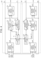
- the first microcomputer 52 includes a first communication unit 71 configured to communicate with the second microcomputer 62.
- the first microcomputer 52 further includes a target overall torque calculation unit 72, a first target torque calculation unit 73, and a first control signal calculation unit 74.
- the target overall torque calculation unit 72 calculates the target overall torque Tw* to be generated in the motor 21.
- the first target torque calculation unit 73 calculates a first target torque T 1 * to be generated in the first winding group 42 in the target overall torque Tw*.
- the first control signal calculation unit 74 calculates the first control signal Sc1.
- the first microcomputer 52 further includes a first abnormality detection unit 75 serving as a current abnormality detection unit and an operation abnormality detection unit.
- the first communication unit 71 exchanges various signals between the calculation units of the first microcomputer 52 and a second communication unit 81 of the second microcomputer 62 described later.
- the first communication unit 71 outputs, to the first target torque calculation unit 73, a current abnormality detection signal Ei2 output from a second abnormality detection unit 85 described later.
- the steering torque Th1, the vehicle speed SPD, the driving assistance command value ⁇ p1 ⁇ , and the rotation angle ⁇ 1 are input to the target overall torque calculation unit 72.
- the target overall torque calculation unit 72 calculates the target overall torque Tw* based on the steering torque Th1 and the vehicle speed SPD.
- the target overall torque calculation unit 72 calculates the target overall torque Tw* based on the driving assistance command value ⁇ p1 ⁇ and the rotation angle ⁇ 1.
- the target overall torque Tw* may be calculated as a value indicating a torque or a value indicating a current.
- the first target torque T1 ⁇ and a second target torque T2* described later may similarly be calculated as values indicating a torque or values indicating a current.
- the target overall torque calculation unit 72 calculates a target overall torque Tw* having a larger absolute value within a range equal to or smaller than the overall rated torque Traw as the absolute value of the steering torque Th1 increases and as the vehicle speed SPD decreases.
- the target overall torque calculation unit 72 acquires the input rotation angle ⁇ 1 by, for example, counting the number of revolutions of the motor 21 from a neutral steering position and converting the rotation angle ⁇ 1 into an absolute angle within a range over 360°.
- the target overall torque calculation unit 72 calculates the pinion angle ⁇ p by multiplying the rotation angle converted into the absolute angle by a conversion factor that is based on a speed reducing ratio of the transmission mechanism 22 and a lead of the conversion mechanism 23. Then, the target overall torque calculation unit 72 calculates the target overall torque Tw* within the range equal to or smaller than the overall rated torque Traw by executing angle feedback control (for example, proportional-integral-derivative (PID) control) based on the pinion angle ⁇ p and the driving assistance command value ⁇ p1 ⁇ so that the pinion angle ⁇ p follows the driving assistance command value ⁇ p1 ⁇ .
- angle feedback control for example, proportional-integral-derivative (PID) control
- PID proportional-integral-derivative
- the target overall torque Tw*, the current abnormality detection signal Ei2, and an operation abnormality detection signal Em2 described later are input to the first target torque calculation unit 73.
- the first target torque calculation unit 73 calculates the first target torque T1 ⁇ based on those condition amounts.
- the first target torque T1 ⁇ is a torque to be generated in the first winding group 42 so as to generate the target overall torque Tw* in the motor 21.
- the first target torque T1 ⁇ , the actual current values I1, and the rotation angle ⁇ 1 are input to the first control signal calculation unit 74.
- the first control signal calculation unit 74 calculates a first current command value based on the first target torque T1 ⁇ . In consideration of the fact that the absolute value of the torque to be generated in the first winding group 42 increases based on an increase in the absolute value of the current to be supplied to the first winding group 42, the first control signal calculation unit 74 calculates a first current command value having a larger absolute value as the absolute value of the first target torque T1 ⁇ increases.
- the first control signal calculation unit 74 calculates a voltage command value of a voltage to be applied to the first drive circuit 53 by executing current feedback control (for example, PID control) based on the actual current values I1 and the first current command value so that the actual current values I1 follow the first current command value.
- the first control signal calculation unit 74 calculates a first control signal (PWM signal) Sc1 having a duty ratio that is based on the voltage command value.
- the actual current values I1 are input to the first abnormality detection unit 75, and various signals are input to the first abnormality detection unit 75 via the first communication unit 71.
- the first abnormality detection unit 75 determines whether a current abnormality such as a wire disconnection or a short circuit occurs in the energization system for the first winding group 42 based on the target overall torque Tw* and the actual current values I1. For example, the first abnormality detection unit 75 determines that the current abnormality of the wire disconnection occurs when the target overall torque Tw* is larger than zero but the actual current values I1 remain zero for a predetermined time or longer.
- the first abnormality detection unit 75 determines that the current abnormality of the short circuit occurs when the target overall torque Tw* is zero but the actual current values I1 remain larger than zero for a predetermined time or longer. When the current abnormality is detected, the first abnormality detection unit 75 outputs, to the first communication unit 71, a current abnormality detection signal Ei 1 indicating that the current abnormality is detected.
- the first abnormality detection unit 75 detects an operation abnormality of the second microcomputer 62 based on a status of communication with the second microcomputer 62 via the first communication unit 71. For example, the first abnormality detection unit 75 determines that the operation abnormality occurs in the second microcomputer 62 when various signals are not input from the second microcomputer 62 via the first communication unit 71. The first abnormality detection unit 75 determines that the operation abnormality does not occur in the second microcomputer 62 when various signals are input from the second microcomputer 62. When the operation abnormality of the second microcomputer 62 is detected, the first abnormality detection unit 75 outputs, to the first target torque calculation unit 73, the operation abnormality detection signal Em2 indicating that the operation abnormality of the second microcomputer 62 is detected.
- the second microcomputer 62 is basically constructed similarly to the first microcomputer 52, and includes the second communication unit 81 configured to exchange various signals with the first communication unit 71.
- the second microcomputer 62 further includes a backup target overall torque calculation unit 82, a second target torque calculation unit 83, and a second control signal calculation unit 84.
- the second target torque calculation unit 83 calculates the second target torque T2* to be generated in the second winding group 43 in the target overall torque Tw*.
- the second control signal calculation unit 84 calculates the second control signal Sc2.
- the second microcomputer 62 further includes the second abnormality detection unit 85 serving as the current abnormality detection unit and the operation abnormality detection unit.
- the second communication unit 81 exchanges various signals between the calculation units of the second microcomputer 62 and the first communication unit 71.
- the second communication unit 81 outputs, to the second target torque calculation unit 83, the target overall torque Tw* and the current abnormality detection signal Ei1 input via the first communication unit 71.
- the steering torque Th2, the vehicle speed SPD, the driving assistance command value ⁇ p2 ⁇ , and the rotation angle ⁇ 2 are input to the target overall torque calculation unit 82.
- the target overall torque calculation unit 82 calculates a backup target overall torque Tw* through arithmetic processing similar to that of the target overall torque calculation unit 72 of the first microcomputer 52.
- the target overall torque Tw* and the current abnormality detection signal Ei1 are input to the second target torque calculation unit 83 via the second communication unit 81, and the backup target overall torque Tw* is input to the second target torque calculation unit 83. Further, an operation abnormality detection signal Em1 described later is input to the second target torque calculation unit 83. As described later, the second target torque calculation unit 83 calculates the second target torque T2* based on those condition amounts.
- the second target torque T2* is a torque to be generated in the second winding group 43 so as to generate the target overall torque Tw* in the motor 21.
- the second target torque T2*, the actual current values I2, and the rotation angle ⁇ 2 are input to the second control signal calculation unit 84.
- the second control signal calculation unit 84 calculates the second control signal (PWM signal) Sc2 through arithmetic processing similar to that of the first control signal calculation unit 74. By outputting the calculated second control signal Sc2 to the second drive circuit 63, the driving electric power is supplied to the second winding group 43 in response to the second control signal Sc2. Thus, the torque indicated by the second target torque T2* is generated in the second winding group 43.
- the second abnormality detection unit 85 is connected to the second communication unit 81.
- the actual current values I2 are input to the second abnormality detection unit 85, and various signals are input to the second abnormality detection unit 85 via the second communication unit 81.
- the second abnormality detection unit 85 determines whether a current abnormality such as a wire disconnection or a short circuit occurs in the energization system for the second winding group 43 based on the target overall torque Tw* and the actual current values I2 through arithmetic processing similar to that of the first abnormality detection unit 75.
- the second abnormality detection unit 85 outputs, to the second communication unit 81, the current abnormality detection signal Ei2 indicating that the current abnormality is detected.
- the second abnormality detection unit 85 detects an operation abnormality of the first microcomputer 52 based on a status of communication with the first microcomputer 52 via the second communication unit 81 through arithmetic processing similar to that of the first abnormality detection unit 75.
- the second abnormality detection unit 85 outputs, to the second target torque calculation unit 83, the operation abnormality detection signal Em1 indicating that the operation abnormality of the first microcomputer 52 is detected.
- the first target torque calculation unit 73 calculates the first target torque T1 ⁇ based on those condition amounts.
- the first target torque calculation unit 73 sets a value that is a half (50%) of the target overall torque Tw* as the first target torque T1 ⁇ .
- the first target torque calculation unit 73 calculates a first target torque T1 ⁇ larger than that in the normal state so that the first target torque T1 ⁇ is equal to the target overall torque Tw*.
- the first target torque calculation unit 73 calculates a first target torque T1* larger than that in the normal state so that the first target torque T1 ⁇ is equal to or close to the target overall torque Tw* over the first rated torque Tra1. That is, when the second winding group 43 cannot generate the torque, the first control unit 51 causes the first winding group 42 to generate a torque larger than that in the normal state, and to temporarily generate a torque larger than the first rated torque Tra1 depending on the magnitude of the target overall torque Tw*.
- the current abnormality detection signal Ei1 and the operation abnormality detection signal Em1 are input to the second target torque calculation unit 83, in addition to the target overall torque Tw*.
- the second target torque calculation unit 83 calculates the second target torque T2* based on those condition amounts.
- the second target torque calculation unit 83 calculates the second target torque T2* based on the backup target overall torque Tw*.
- the second target torque calculation unit 83 sets a value that is a half (50%) of the target overall torque Tw* as the second target torque T2*.
- the second target torque calculation unit 83 calculates a second target torque T2* larger than that in the normal state so that the second target torque T2* is equal to the target overall torque Tw*.
- the second target torque calculation unit 83 calculates a second target torque T2* larger than that in the normal state so that the second target torque T2* is equal to or close to the target overall torque Tw* over the second rated torque Tra2.
- the second control unit 61 causes the second winding group 43 to generate a torque larger than that in the normal state, and to temporarily generate a torque larger than the second rated torque Tra2 depending on the magnitude of the target overall torque Tw*.
- the target overall torque Tw* is assumed to be 60% of the overall rated torque Traw as illustrated in FIG. 3Ato FIG. 3C .
- the first winding group 42 outputs a torque that is 60% of the first rated torque Tra1 (30% of the overall rated torque Traw)
- the second winding group 43 outputs a torque that is 60% of the second rated torque Tra2 (30% of the overall rated torque Traw).
- the first winding group 42 when the second winding group 43 cannot output the torque due to the occurrence of a current abnormality, the first winding group 42 temporarily outputs a torque that is 120% of the first rated torque Tra1. Therefore, the entire motor 21 outputs a torque that is 60% of the overall rated torque Traw. Thus, deficiency of the torque to be applied from the motor 21 is temporarily suppressed even in the event of the abnormality.
- the first power supply line 55 is provided with a first voltage sensor 91 configured to detect a power supply voltage Vb1 of the on-board power supply 56.
- the power supply voltage Vb1 is input to the first microcomputer 52 in addition to the vehicle speed SPD, the steering torque Th1, the driving assistance command value ⁇ p1 ⁇ , the rotation angle ⁇ 1, and the actual current values I1.
- the second drive circuit 63 of this embodiment is supplied with electric power from an on-board power supply 106 that is an external power supply different from that for the first drive circuit 53. Specifically, the second drive circuit 63 is connected, via the second power supply line 65, to the on-board power supply 106 mounted on the vehicle, but is not connected to the on-board power supply 56.
- the second power supply line 65 is provided with a power supply relay 107 and a second voltage sensor 101.
- the power supply relay 107 is turned ON or OFF in response to a signal from the activation switch of the vehicle.
- the second voltage sensor 101 detects a power supply voltage Vb2 of the on-board power supply 106.
- the second drive circuit 63 can supply the driving electric power to the second winding group 43 based on the power supply voltage of the on-board power supply 106 while the power supply relay 107 is turned ON and the second power supply line 65 is brought into conduction.
- the electric power of the on-board power supply 106 is supplied to the second microcomputer 62 via a power feed line (not illustrated).
- the power supply voltage Vb2 is input to the second microcomputer 62 in addition to the vehicle speed SPD, the steering torque Th2, the driving assistance command value ⁇ p2 ⁇ , the rotation angle ⁇ 2, and the actual current values I2.
- the first microcomputer 52 of this embodiment includes a first restriction torque calculation unit 111 configured to calculate a first restriction torque Tre1 for restricting the first target torque T1 ⁇ to the first rated torque Tra1 or smaller.
- the power supply voltage Vb1 is input to the first restriction torque calculation unit 111.
- the first restriction torque calculation unit 111 calculates the first restriction torque Tre1 based on the power supply voltage Vb1 of the on-board power supply 56 from the viewpoint of suppressing a decrease in the power supply voltage Vb 1.
- the first restriction torque calculation unit 111 calculates a first restriction torque Tre1 having a smaller absolute value based on a decrease in the absolute value of the power supply voltage Vb1.
- the first restriction torque calculation unit 111 calculates a first restriction torque Tre1 equal to the first rated torque Tra1.
- the voltage threshold is preset based on a lower limit value of an assist assurance voltage range of the steering apparatus 2.
- the calculated first restriction torque Tre1 is output to the first target torque calculation unit 73 and the first communication unit 71.
- the second microcomputer 62 of this embodiment includes a second restriction torque calculation unit 121 configured to calculate a second restriction torque Tre2 for restricting the second target torque T2* to the second rated torque Tra2 or smaller.
- the power supply voltage Vb2 is input to the second restriction torque calculation unit 121.
- the second restriction torque calculation unit 121 calculates the second restriction torque Tre2 based on the power supply voltage Vb2 through arithmetic processing similar to that of the first restriction torque calculation unit 111.
- the calculated second restriction torque Tre2 is output to the second target torque calculation unit 83 and the second communication unit 81.
- the first target torque calculation unit 73 calculates a first target torque T1 ⁇ larger than that in the normal state so that the first target torque T1 ⁇ is equal to the target overall torque Tw*.
- the first target torque calculation unit 73 calculates a first target torque T1* larger than that in the normal state so that the first target torque T1 ⁇ is equal to or close to the target overall torque Tw* over the first rated torque Tra1.
- the first target torque calculation unit 73 calculates the first target torque T1 ⁇ similarly to the first embodiment.
- the second target torque calculation unit 83 calculates a second target torque T2* larger than that in the normal state so that the second target torque T2* is equal to the target overall torque Tw*.
- the second target torque calculation unit 83 calculates a second target torque T2* larger than that in the normal state so that the second target torque T2* is equal to or close to the target overall torque Tw* over the second rated torque Tra2.
- the second target torque calculation unit 83 calculates the second target torque T2* similarly to the first embodiment.
- This embodiment produces actions and effects similar to the actions and effects (1) to (3) of the first embodiment.
- the on-board power supply 56 is connected to the first control unit 51, and the on-board power supply 106 is connected to the second control unit 61.
- the steering controller 1 includes the first restriction torque calculation unit 111 configured to calculate the first restriction torque Tre1 based on the power supply voltage Vb1, and the second restriction torque calculation unit 121 configured to calculate the second restriction torque Tre2 based on the power supply voltage Vb2.
- the steering controller 1 supplies the driving electric power so that the first winding group 42 or the second winding group 43 that is not in the restricted state generates a torque larger than the first rated torque Tra1 or the second rated torque Tra2. Therefore, the deficiency of the torque to be applied from the motor 21 can temporarily be suppressed in the restricted state in which the power supply voltage Vb1 or Vb2 decreases and the first winding group 42 or the second winding group 43 can only generate a torque smaller than the first rated torque Tra1 or the second rated torque Tra2.
- the first control unit 51 may not include the first abnormality detection unit 75, and the second control unit 61 may not include the second abnormality detection unit 85.
- the first abnormality detection unit 75 may detect a wire disconnection or a short circuit alone.
- the second abnormality detection unit 85 may detect a wire disconnection or a short circuit alone.
- the current abnormality is detected based on the target overall torque Tw* and the actual current values I1, but the present invention is not limited to this case.
- the current abnormality may be detected based on a current command value and the actual current values I1.
- the detection method may be changed as appropriate.
- the detection method for the operation abnormality may be changed as appropriate.
- the driving assistance command values ⁇ p1 ⁇ and ⁇ p2 ⁇ may not be input from the driving assistance controller 35 to the steering controller 1.
- control is made over the motor 21 including the first winding group 42 and the second winding group 43 having the same specifications of the coils, but the present invention is not limited to this case. Control may be made over a motor in which specifications and individual rated torques differ from each other between winding groups of energization systems.
- the steering apparatus 2 is constructed as the EPS, and control is made over the motor 21 configured to apply the assist torque.
- the present invention is not limited to this case.
- the steering apparatus 2 may be constructed as a steer-by-wire type apparatus in which power transmission between a steering portion and a steered portion is separated, and control may be made over a motor configured to apply a steering operation torque for turning steered wheels.
- the steering controller 1 of each of the embodiments described above controls the motor 21 including the first winding group 42 and the second winding group 43 having two separate energization systems.
- the present invention is not limited to this case.
- the steering controller 1 may control a motor including winding groups having three or more separate systems.
Landscapes
- Engineering & Computer Science (AREA)
- Chemical & Material Sciences (AREA)
- Combustion & Propulsion (AREA)
- Transportation (AREA)
- Mechanical Engineering (AREA)
- Power Engineering (AREA)
- Steering Control In Accordance With Driving Conditions (AREA)
- Control Of Ac Motors In General (AREA)
- Control Of Electric Motors In General (AREA)
- Power Steering Mechanism (AREA)
Claims (4)
- Motorsteuerung, die so konfiguriert ist, dass sie einen Motor steuert, wobei der Motor so konfiguriert ist, dass er ein Drehmoment erzeugt, das an einen Lenkmechanismus angelegt werden soll, wobei der Motor eine Mehrzahl von Wicklungsgruppen enthält, wobei der Motor mit einer Mehrzahl von Erregersystemen versehen ist, wobei jede der Wicklungsgruppen in einem entsprechenden der Erregersysteme enthalten ist, wobei die Motorsteuerung eine Mehrzahl von Prozessoren (51; 61) aufweist, wobei jeder der Prozessoren (51; 61) so konfiguriert ist, dass er unabhängig eine Zufuhr von elektrischer Antriebsenergie zu jeder der Wicklungsgruppen in dem entsprechenden der Erregersysteme steuert,jeder der Prozessoren (51; 61) so konfiguriert ist, dass er jeweilige Steuersignale basierend auf Ziel-Einzeldrehmomenten berechnet, die für jede der Wicklungsgruppen in dem entsprechenden der Erregersysteme von einem in dem Motor zu erzeugenden Ziel-Gesamtdrehmoment aufgeteilt sind,jeder der Prozessoren (51; 61) Antriebsschaltungen enthält, die so konfiguriert sind, dass sie die elektrische Antriebsenergie an jede der Wicklungsgruppen in dem entsprechenden der Erregersysteme basierend auf den Steuersignalen liefern,jeder der Prozessoren (51; 61) so konfiguriert ist, dass er die Ziel-Einzeldrehmomente derart berechnet, dass jedes der Ziel-Einzeldrehmomente gleich einem Einzel-Nenndrehmoment oder kleiner als dieses ist, das so festgesetzt ist, dass es kleiner als ein Einzel-Grenzdrehmoment ist, das in Abhängigkeit von einer Struktur des Motors als eine Grenze eines Drehmoments bestimmt wird, das in jeder der Wicklungsgruppen in dem entsprechenden der Erregungssysteme ausgegeben werden soll,jeder der Prozessoren (51; 61) derart konfiguriert ist, dass, wenn eine Abnormalität auftritt, bei der ein in einer der Wicklungsgruppen in dem entsprechenden der Erregersysteme zu erzeugendes Drehmoment kleiner als das Einzel-Nenndrehmoment ist, und wenn das Ziel-Gesamtdrehmoment größer als eine Summe des Einzel-Nenndrehmoments für die Wicklungsgruppe in dem entsprechenden der Erregersysteme ist, in dem die Abnormalität nicht auftritt, der Prozessor (51; 61), der die Zufuhr von elektrischer Antriebsenergie zu der Wicklungsgruppe in dem entsprechenden der Erregungssysteme steuert, in dem die Abnormalität nicht auftritt, aus der Mehrzahl der Prozessoren (51; 61) die Zufuhr der elektrischen Antriebsenergie derart steuert, dass die Wicklungsgruppe ein Drehmoment erzeugt, das größer als das Einzel-Nenndrehmoment ist, derart, dass ein Mangel des vom Motor anzulegenden Drehmoments vorübergehend für eine kurze Zeit unterdrückt werden kann, bis der Motor oder die Antriebsschaltung überhitzt ist.
- Motorsteuerung nach Anspruch 1, wobei:jeder der Prozessoren (51; 61) so konfiguriert ist, dass er eine Stromabnormalität erfasst, die eine Drahtunterbrechung und/oder einen Kurzschluss in dem Erregersystem enthält; unddie Prozessoren (51; 61) derart konfiguriert sind, dass, wenn die Stromabnormalität erfasst wird und das Ziel-Gesamtdrehmoment größer ist als die Summe des Einzel-Nenndrehmoments für die Wicklungsgruppe in dem entsprechenden der Erregersysteme, in dem die Stromabnormalität nicht auftritt, der Prozessor (51; 61), der die Zufuhr von elektrischer Antriebsenergie zu der Wicklungsgruppe in dem entsprechenden der Erregungssysteme steuert, in dem die Stromabnormalität nicht auftritt, aus der Mehrzahl der Prozessoren (51; 61) die Zufuhr der elektrischen Antriebsenergie derart steuert, dass die Wicklungsgruppe ein Drehmoment erzeugt, das größer als das Einzel-Nenndrehmoment ist.
- Motorsteuerung nach Anspruch 1 oder 2, wobei:jeder der Prozessoren (51; 61) so konfiguriert ist, dass er eine Betriebsabnormalität des Prozessors (61; 51) erfasst, der so konfiguriert ist, dass er die Zufuhr der elektrischen Antriebsenergie zu der Wicklungsgruppe in dem entsprechenden des anderen Erregersystems steuert; unddie Prozessoren (51; 61) derart konfiguriert sind, dass, wenn die Betriebsabnormalität erfasst wird und wenn das Ziel-Gesamtdrehmoment größer ist als die Summe des Einzel-Nenndrehmoments für die Wicklungsgruppe in dem entsprechenden der Erregersysteme, in dem die Betriebsabnormalität nicht auftritt, der Prozessor (51; 61), der die Zufuhr von elektrischer Antriebsenergie zu der Wicklungsgruppe in dem entsprechenden der Erregungssysteme steuert, in dem die Betriebsabnormalität nicht auftritt, aus der Mehrzahl der Prozessoren (51; 61) die Zufuhr der elektrischen Antriebsenergie derart steuert, dass die Wicklungsgruppe ein Drehmoment erzeugt, das größer als das Einzel-Nenndrehmoment ist.
- Motorsteuerung nach einem der Ansprüche 1 bis 3, wobei:jeder der Prozessoren (51; 61) mit einzelnen externen Energieversorgungen verbunden ist;die Prozessoren (51; 61) so konfiguriert sind, dass sie Einzel-Begrenzungsdrehmomente berechnen, um die Ziel-Einzeldrehmomente auf die Ziel-Nenndrehmomente oder kleiner als diese zu begrenzen, basierend auf den Energieversorgungsspannungen der externen Stromversorgungen; unddie Prozessoren (51; 61) derart konfiguriert sind, dass, wenn sich eine der Wicklungsgruppen in dem entsprechenden der Erregersysteme in einem begrenzenden Zustand befindet, in dem das Einzel-Begrenzungsdrehmoment kleiner als das Einzel-Nenndrehmoment ist, und wenn das Ziel-Gesamtdrehmoment größer als eine Summe des Einzel-Nenndrehmoments der Wicklungsgruppe in dem entsprechenden der Erregersysteme, das sich nicht in dem begrenzenden Zustand befindet, und des Einzel-Begrenzungsdrehmoments der Wicklungsgruppe in dem entsprechenden des Erregersystems, das sich in dem begrenzenden Zustand befindet, ist, der Prozessor (51; 61), der die Zufuhr von elektrischer Antriebsenergie zu der Wicklungsgruppe in dem entsprechenden der Erregungssysteme, das sich nicht in dem begrenzenden Zustand befindet, steuert, aus der Mehrzahl von Prozessoren (51; 61) die Zufuhr der elektrischen Antriebsenergie derart steuert, dass die Wicklungsgruppe ein Drehmoment erzeugt, das größer ist als das Einzel-Nennmoment.
Applications Claiming Priority (1)
| Application Number | Priority Date | Filing Date | Title |
|---|---|---|---|
| JP2018239458A JP7230488B2 (ja) | 2018-12-21 | 2018-12-21 | モータ制御装置 |
Publications (2)
| Publication Number | Publication Date |
|---|---|
| EP3715214A1 EP3715214A1 (de) | 2020-09-30 |
| EP3715214B1 true EP3715214B1 (de) | 2023-02-22 |
Family
ID=69185149
Family Applications (1)
| Application Number | Title | Priority Date | Filing Date |
|---|---|---|---|
| EP19218480.2A Active EP3715214B1 (de) | 2018-12-21 | 2019-12-20 | Motorsteuergerät |
Country Status (4)
| Country | Link |
|---|---|
| US (1) | US11027772B2 (de) |
| EP (1) | EP3715214B1 (de) |
| JP (1) | JP7230488B2 (de) |
| CN (1) | CN111348103B (de) |
Families Citing this family (7)
| Publication number | Priority date | Publication date | Assignee | Title |
|---|---|---|---|---|
| KR102771683B1 (ko) * | 2019-07-05 | 2025-02-25 | 주식회사 엘지에너지솔루션 | 배터리 셀 진단 장치 및 방법 |
| JP7205414B2 (ja) * | 2019-08-15 | 2023-01-17 | 株式会社デンソー | 回転電機制御装置 |
| JP7650571B2 (ja) * | 2021-07-05 | 2025-03-25 | トヨタ自動車株式会社 | ステアリングシステム |
| WO2023046265A1 (en) | 2021-09-22 | 2023-03-30 | Thyssenkrupp Presta Ag | Method to control a steering system of a motor vehicle with increased maximum output power of actuator motor after unilateral failure of the redundant system |
| KR102876490B1 (ko) * | 2022-04-26 | 2025-10-24 | 에이치엘만도 주식회사 | 이중화 전동식 조향시스템의 초기 검증 방법 |
| SE547648C2 (en) * | 2023-11-10 | 2025-11-04 | Chassis Autonomy Sba Ab | Dual-Motor Steer-by-Wire Steering Assembly |
| CN117341804B (zh) * | 2023-12-04 | 2024-02-23 | 上海集度汽车有限公司 | 线控转向系统、车辆、力反馈方法、装置及存储介质 |
Family Cites Families (16)
| Publication number | Priority date | Publication date | Assignee | Title |
|---|---|---|---|---|
| JP4187308B2 (ja) * | 1998-06-16 | 2008-11-26 | 日本オーチス・エレベータ株式会社 | 可変速駆動装置 |
| DE10053818B4 (de) | 2000-10-30 | 2006-03-30 | Sauer-Danfoss Holding Aps | Elektrisches Lenksystem |
| JP2004274928A (ja) | 2003-03-11 | 2004-09-30 | Asmo Co Ltd | アクチュエータの制御装置 |
| KR101062602B1 (ko) * | 2007-06-07 | 2011-09-06 | 미쓰비시덴키 가부시키가이샤 | 전동기 제어 장치 |
| JP5387989B2 (ja) | 2009-12-25 | 2014-01-15 | 株式会社デンソー | 電動機駆動装置、および、これを用いた電動パワーステアリング装置 |
| CN101734135A (zh) * | 2009-12-29 | 2010-06-16 | 东莞市精航达电动转向系统有限公司 | 一种车辆电动助力转向控制方法及其控制装置 |
| JP5653386B2 (ja) | 2012-05-09 | 2015-01-14 | 三菱電機株式会社 | モータ制御装置およびそれを用いた電動パワーステアリング装置 |
| JP5569626B1 (ja) * | 2013-06-17 | 2014-08-13 | 日本精工株式会社 | モータ制御装置、これを使用した電動パワーステアリング装置及び車両 |
| EP3113355B1 (de) * | 2014-02-28 | 2019-05-22 | NSK Ltd. | Motorsteuerungsvorrichtung und elektrische servolenkvorrichtung und fahrzeug mit dieser motorsteuerungsvorrichtung |
| JP6040963B2 (ja) * | 2014-07-07 | 2016-12-07 | 株式会社デンソー | 回転機の制御装置 |
| JP6488089B2 (ja) * | 2014-09-11 | 2019-03-20 | 日立オートモティブシステムズ株式会社 | 電動機の制御装置及び制御方法 |
| CN108473157A (zh) * | 2016-01-25 | 2018-08-31 | 日立汽车系统株式会社 | 操舵控制装置 |
| JP6472570B2 (ja) | 2016-03-14 | 2019-02-20 | 三菱電機株式会社 | 電動モータ制御システム及びそれを備えた電動パワーステアリング装置 |
| JP6642278B2 (ja) | 2016-05-27 | 2020-02-05 | 株式会社デンソー | 回転電機制御装置、および、これを用いた電動パワーステアリング装置 |
| JP6662721B2 (ja) | 2016-06-22 | 2020-03-11 | 株式会社ジェイテクト | 制御装置、モータ制御装置、及び電動パワーステアリング装置 |
| JP6769328B2 (ja) * | 2017-02-10 | 2020-10-14 | 株式会社デンソー | 回転電機制御装置、および、これを用いた電動パワーステアリング装置 |
-
2018
- 2018-12-21 JP JP2018239458A patent/JP7230488B2/ja active Active
-
2019
- 2019-12-18 CN CN201911310357.9A patent/CN111348103B/zh active Active
- 2019-12-19 US US16/720,248 patent/US11027772B2/en active Active
- 2019-12-20 EP EP19218480.2A patent/EP3715214B1/de active Active
Also Published As
| Publication number | Publication date |
|---|---|
| US20200198695A1 (en) | 2020-06-25 |
| JP2020102942A (ja) | 2020-07-02 |
| US11027772B2 (en) | 2021-06-08 |
| CN111348103B (zh) | 2024-10-15 |
| CN111348103A (zh) | 2020-06-30 |
| EP3715214A1 (de) | 2020-09-30 |
| JP7230488B2 (ja) | 2023-03-01 |
Similar Documents
| Publication | Publication Date | Title |
|---|---|---|
| EP3715214B1 (de) | Motorsteuergerät | |
| CN103857582B (zh) | 电动助力转向设备 | |
| JP5930058B2 (ja) | ステアリング制御装置、ステアリング制御方法 | |
| US11427246B2 (en) | Steering system | |
| JP5023833B2 (ja) | 電動パワーステアリング装置及び異常検出方法 | |
| US8996252B2 (en) | Electric power steering apparatus | |
| JP5224032B2 (ja) | 操舵制御装置 | |
| US20200023890A1 (en) | Motor controller | |
| US20200136543A1 (en) | Motor control device and motor control method | |
| CN110816645A (zh) | 车辆控制装置 | |
| JP5310579B2 (ja) | 電動パワーステアリング装置 | |
| JP2013159165A (ja) | 電動パワーステアリング装置 | |
| US8983730B2 (en) | Electric power steering apparatus | |
| JP5991264B2 (ja) | 電動パワーステアリング装置 | |
| JP2014201199A (ja) | 電動パワーステアリング装置 | |
| JP4778248B2 (ja) | 電動パワーステアリング装置 | |
| JP4644013B2 (ja) | 電動パワーステアリング装置 | |
| JP5092509B2 (ja) | 電動パワーステアリング装置 | |
| JP5169410B2 (ja) | 電動パワーステアリング装置 | |
| JP6439632B2 (ja) | 電動パワーステアリング装置 | |
| JP6439631B2 (ja) | 電動パワーステアリング装置 | |
| JP5131435B2 (ja) | 電動パワーステアリング装置 | |
| JP2017022915A (ja) | 電動モータ制御装置 |
Legal Events
| Date | Code | Title | Description |
|---|---|---|---|
| PUAI | Public reference made under article 153(3) epc to a published international application that has entered the european phase |
Free format text: ORIGINAL CODE: 0009012 |
|
| STAA | Information on the status of an ep patent application or granted ep patent |
Free format text: STATUS: THE APPLICATION HAS BEEN PUBLISHED |
|
| AK | Designated contracting states |
Kind code of ref document: A1 Designated state(s): AL AT BE BG CH CY CZ DE DK EE ES FI FR GB GR HR HU IE IS IT LI LT LU LV MC MK MT NL NO PL PT RO RS SE SI SK SM TR |
|
| AX | Request for extension of the european patent |
Extension state: BA ME |
|
| STAA | Information on the status of an ep patent application or granted ep patent |
Free format text: STATUS: REQUEST FOR EXAMINATION WAS MADE |
|
| 17P | Request for examination filed |
Effective date: 20210324 |
|
| RBV | Designated contracting states (corrected) |
Designated state(s): AL AT BE BG CH CY CZ DE DK EE ES FI FR GB GR HR HU IE IS IT LI LT LU LV MC MK MT NL NO PL PT RO RS SE SI SK SM TR |
|
| STAA | Information on the status of an ep patent application or granted ep patent |
Free format text: STATUS: EXAMINATION IS IN PROGRESS |
|
| 17Q | First examination report despatched |
Effective date: 20210705 |
|
| RAP3 | Party data changed (applicant data changed or rights of an application transferred) |
Owner name: JTEKT CORPORATION |
|
| GRAP | Despatch of communication of intention to grant a patent |
Free format text: ORIGINAL CODE: EPIDOSNIGR1 |
|
| STAA | Information on the status of an ep patent application or granted ep patent |
Free format text: STATUS: GRANT OF PATENT IS INTENDED |
|
| INTG | Intention to grant announced |
Effective date: 20221012 |
|
| GRAS | Grant fee paid |
Free format text: ORIGINAL CODE: EPIDOSNIGR3 |
|
| GRAA | (expected) grant |
Free format text: ORIGINAL CODE: 0009210 |
|
| STAA | Information on the status of an ep patent application or granted ep patent |
Free format text: STATUS: THE PATENT HAS BEEN GRANTED |
|
| AK | Designated contracting states |
Kind code of ref document: B1 Designated state(s): AL AT BE BG CH CY CZ DE DK EE ES FI FR GB GR HR HU IE IS IT LI LT LU LV MC MK MT NL NO PL PT RO RS SE SI SK SM TR |
|
| REG | Reference to a national code |
Ref country code: GB Ref legal event code: FG4D |
|
| REG | Reference to a national code |
Ref country code: CH Ref legal event code: EP |
|
| REG | Reference to a national code |
Ref country code: AT Ref legal event code: REF Ref document number: 1549339 Country of ref document: AT Kind code of ref document: T Effective date: 20230315 Ref country code: IE Ref legal event code: FG4D |
|
| REG | Reference to a national code |
Ref country code: DE Ref legal event code: R096 Ref document number: 602019025497 Country of ref document: DE |
|
| REG | Reference to a national code |
Ref country code: LT Ref legal event code: MG9D |
|
| REG | Reference to a national code |
Ref country code: NL Ref legal event code: MP Effective date: 20230222 |
|
| REG | Reference to a national code |
Ref country code: AT Ref legal event code: MK05 Ref document number: 1549339 Country of ref document: AT Kind code of ref document: T Effective date: 20230222 |
|
| PG25 | Lapsed in a contracting state [announced via postgrant information from national office to epo] |
Ref country code: RS Free format text: LAPSE BECAUSE OF FAILURE TO SUBMIT A TRANSLATION OF THE DESCRIPTION OR TO PAY THE FEE WITHIN THE PRESCRIBED TIME-LIMIT Effective date: 20230222 Ref country code: PT Free format text: LAPSE BECAUSE OF FAILURE TO SUBMIT A TRANSLATION OF THE DESCRIPTION OR TO PAY THE FEE WITHIN THE PRESCRIBED TIME-LIMIT Effective date: 20230622 Ref country code: NO Free format text: LAPSE BECAUSE OF FAILURE TO SUBMIT A TRANSLATION OF THE DESCRIPTION OR TO PAY THE FEE WITHIN THE PRESCRIBED TIME-LIMIT Effective date: 20230522 Ref country code: NL Free format text: LAPSE BECAUSE OF FAILURE TO SUBMIT A TRANSLATION OF THE DESCRIPTION OR TO PAY THE FEE WITHIN THE PRESCRIBED TIME-LIMIT Effective date: 20230222 Ref country code: LV Free format text: LAPSE BECAUSE OF FAILURE TO SUBMIT A TRANSLATION OF THE DESCRIPTION OR TO PAY THE FEE WITHIN THE PRESCRIBED TIME-LIMIT Effective date: 20230222 Ref country code: LT Free format text: LAPSE BECAUSE OF FAILURE TO SUBMIT A TRANSLATION OF THE DESCRIPTION OR TO PAY THE FEE WITHIN THE PRESCRIBED TIME-LIMIT Effective date: 20230222 Ref country code: HR Free format text: LAPSE BECAUSE OF FAILURE TO SUBMIT A TRANSLATION OF THE DESCRIPTION OR TO PAY THE FEE WITHIN THE PRESCRIBED TIME-LIMIT Effective date: 20230222 Ref country code: ES Free format text: LAPSE BECAUSE OF FAILURE TO SUBMIT A TRANSLATION OF THE DESCRIPTION OR TO PAY THE FEE WITHIN THE PRESCRIBED TIME-LIMIT Effective date: 20230222 Ref country code: AT Free format text: LAPSE BECAUSE OF FAILURE TO SUBMIT A TRANSLATION OF THE DESCRIPTION OR TO PAY THE FEE WITHIN THE PRESCRIBED TIME-LIMIT Effective date: 20230222 |
|
| PG25 | Lapsed in a contracting state [announced via postgrant information from national office to epo] |
Ref country code: SE Free format text: LAPSE BECAUSE OF FAILURE TO SUBMIT A TRANSLATION OF THE DESCRIPTION OR TO PAY THE FEE WITHIN THE PRESCRIBED TIME-LIMIT Effective date: 20230222 Ref country code: PL Free format text: LAPSE BECAUSE OF FAILURE TO SUBMIT A TRANSLATION OF THE DESCRIPTION OR TO PAY THE FEE WITHIN THE PRESCRIBED TIME-LIMIT Effective date: 20230222 Ref country code: IS Free format text: LAPSE BECAUSE OF FAILURE TO SUBMIT A TRANSLATION OF THE DESCRIPTION OR TO PAY THE FEE WITHIN THE PRESCRIBED TIME-LIMIT Effective date: 20230622 Ref country code: GR Free format text: LAPSE BECAUSE OF FAILURE TO SUBMIT A TRANSLATION OF THE DESCRIPTION OR TO PAY THE FEE WITHIN THE PRESCRIBED TIME-LIMIT Effective date: 20230523 Ref country code: FI Free format text: LAPSE BECAUSE OF FAILURE TO SUBMIT A TRANSLATION OF THE DESCRIPTION OR TO PAY THE FEE WITHIN THE PRESCRIBED TIME-LIMIT Effective date: 20230222 |
|
| PG25 | Lapsed in a contracting state [announced via postgrant information from national office to epo] |
Ref country code: SM Free format text: LAPSE BECAUSE OF FAILURE TO SUBMIT A TRANSLATION OF THE DESCRIPTION OR TO PAY THE FEE WITHIN THE PRESCRIBED TIME-LIMIT Effective date: 20230222 Ref country code: RO Free format text: LAPSE BECAUSE OF FAILURE TO SUBMIT A TRANSLATION OF THE DESCRIPTION OR TO PAY THE FEE WITHIN THE PRESCRIBED TIME-LIMIT Effective date: 20230222 Ref country code: EE Free format text: LAPSE BECAUSE OF FAILURE TO SUBMIT A TRANSLATION OF THE DESCRIPTION OR TO PAY THE FEE WITHIN THE PRESCRIBED TIME-LIMIT Effective date: 20230222 Ref country code: DK Free format text: LAPSE BECAUSE OF FAILURE TO SUBMIT A TRANSLATION OF THE DESCRIPTION OR TO PAY THE FEE WITHIN THE PRESCRIBED TIME-LIMIT Effective date: 20230222 Ref country code: CZ Free format text: LAPSE BECAUSE OF FAILURE TO SUBMIT A TRANSLATION OF THE DESCRIPTION OR TO PAY THE FEE WITHIN THE PRESCRIBED TIME-LIMIT Effective date: 20230222 |
|
| REG | Reference to a national code |
Ref country code: DE Ref legal event code: R097 Ref document number: 602019025497 Country of ref document: DE |
|
| PG25 | Lapsed in a contracting state [announced via postgrant information from national office to epo] |
Ref country code: SK Free format text: LAPSE BECAUSE OF FAILURE TO SUBMIT A TRANSLATION OF THE DESCRIPTION OR TO PAY THE FEE WITHIN THE PRESCRIBED TIME-LIMIT Effective date: 20230222 |
|
| PLBE | No opposition filed within time limit |
Free format text: ORIGINAL CODE: 0009261 |
|
| STAA | Information on the status of an ep patent application or granted ep patent |
Free format text: STATUS: NO OPPOSITION FILED WITHIN TIME LIMIT |
|
| 26N | No opposition filed |
Effective date: 20231123 |
|
| PG25 | Lapsed in a contracting state [announced via postgrant information from national office to epo] |
Ref country code: SI Free format text: LAPSE BECAUSE OF FAILURE TO SUBMIT A TRANSLATION OF THE DESCRIPTION OR TO PAY THE FEE WITHIN THE PRESCRIBED TIME-LIMIT Effective date: 20230222 |
|
| PG25 | Lapsed in a contracting state [announced via postgrant information from national office to epo] |
Ref country code: IT Free format text: LAPSE BECAUSE OF FAILURE TO SUBMIT A TRANSLATION OF THE DESCRIPTION OR TO PAY THE FEE WITHIN THE PRESCRIBED TIME-LIMIT Effective date: 20230222 |
|
| REG | Reference to a national code |
Ref country code: CH Ref legal event code: PL |
|
| PG25 | Lapsed in a contracting state [announced via postgrant information from national office to epo] |
Ref country code: LU Free format text: LAPSE BECAUSE OF NON-PAYMENT OF DUE FEES Effective date: 20231220 |
|
| PG25 | Lapsed in a contracting state [announced via postgrant information from national office to epo] |
Ref country code: MC Free format text: LAPSE BECAUSE OF FAILURE TO SUBMIT A TRANSLATION OF THE DESCRIPTION OR TO PAY THE FEE WITHIN THE PRESCRIBED TIME-LIMIT Effective date: 20230222 |
|
| GBPC | Gb: european patent ceased through non-payment of renewal fee |
Effective date: 20231220 |
|
| REG | Reference to a national code |
Ref country code: BE Ref legal event code: MM Effective date: 20231231 |
|
| PG25 | Lapsed in a contracting state [announced via postgrant information from national office to epo] |
Ref country code: MC Free format text: LAPSE BECAUSE OF FAILURE TO SUBMIT A TRANSLATION OF THE DESCRIPTION OR TO PAY THE FEE WITHIN THE PRESCRIBED TIME-LIMIT Effective date: 20230222 Ref country code: LU Free format text: LAPSE BECAUSE OF NON-PAYMENT OF DUE FEES Effective date: 20231220 |
|
| REG | Reference to a national code |
Ref country code: IE Ref legal event code: MM4A |
|
| PG25 | Lapsed in a contracting state [announced via postgrant information from national office to epo] |
Ref country code: IE Free format text: LAPSE BECAUSE OF NON-PAYMENT OF DUE FEES Effective date: 20231220 |
|
| PG25 | Lapsed in a contracting state [announced via postgrant information from national office to epo] |
Ref country code: GB Free format text: LAPSE BECAUSE OF NON-PAYMENT OF DUE FEES Effective date: 20231220 |
|
| PG25 | Lapsed in a contracting state [announced via postgrant information from national office to epo] |
Ref country code: BE Free format text: LAPSE BECAUSE OF NON-PAYMENT OF DUE FEES Effective date: 20231231 |
|
| PG25 | Lapsed in a contracting state [announced via postgrant information from national office to epo] |
Ref country code: CH Free format text: LAPSE BECAUSE OF NON-PAYMENT OF DUE FEES Effective date: 20231231 |
|
| PG25 | Lapsed in a contracting state [announced via postgrant information from national office to epo] |
Ref country code: IE Free format text: LAPSE BECAUSE OF NON-PAYMENT OF DUE FEES Effective date: 20231220 Ref country code: GB Free format text: LAPSE BECAUSE OF NON-PAYMENT OF DUE FEES Effective date: 20231220 Ref country code: CH Free format text: LAPSE BECAUSE OF NON-PAYMENT OF DUE FEES Effective date: 20231231 Ref country code: BE Free format text: LAPSE BECAUSE OF NON-PAYMENT OF DUE FEES Effective date: 20231231 |
|
| PG25 | Lapsed in a contracting state [announced via postgrant information from national office to epo] |
Ref country code: BG Free format text: LAPSE BECAUSE OF FAILURE TO SUBMIT A TRANSLATION OF THE DESCRIPTION OR TO PAY THE FEE WITHIN THE PRESCRIBED TIME-LIMIT Effective date: 20230222 |
|
| PG25 | Lapsed in a contracting state [announced via postgrant information from national office to epo] |
Ref country code: BG Free format text: LAPSE BECAUSE OF FAILURE TO SUBMIT A TRANSLATION OF THE DESCRIPTION OR TO PAY THE FEE WITHIN THE PRESCRIBED TIME-LIMIT Effective date: 20230222 |
|
| PG25 | Lapsed in a contracting state [announced via postgrant information from national office to epo] |
Ref country code: CY Free format text: LAPSE BECAUSE OF FAILURE TO SUBMIT A TRANSLATION OF THE DESCRIPTION OR TO PAY THE FEE WITHIN THE PRESCRIBED TIME-LIMIT; INVALID AB INITIO Effective date: 20191220 |
|
| PG25 | Lapsed in a contracting state [announced via postgrant information from national office to epo] |
Ref country code: HU Free format text: LAPSE BECAUSE OF FAILURE TO SUBMIT A TRANSLATION OF THE DESCRIPTION OR TO PAY THE FEE WITHIN THE PRESCRIBED TIME-LIMIT; INVALID AB INITIO Effective date: 20191220 |
|
| PG25 | Lapsed in a contracting state [announced via postgrant information from national office to epo] |
Ref country code: TR Free format text: LAPSE BECAUSE OF FAILURE TO SUBMIT A TRANSLATION OF THE DESCRIPTION OR TO PAY THE FEE WITHIN THE PRESCRIBED TIME-LIMIT Effective date: 20230222 |
|
| PGFP | Annual fee paid to national office [announced via postgrant information from national office to epo] |
Ref country code: DE Payment date: 20251028 Year of fee payment: 7 |
|
| PGFP | Annual fee paid to national office [announced via postgrant information from national office to epo] |
Ref country code: FR Payment date: 20251110 Year of fee payment: 7 |