EP3716471A1 - Entraînement à pivotement et déploiement pour panneaux solaires - Google Patents
Entraînement à pivotement et déploiement pour panneaux solaires Download PDFInfo
- Publication number
- EP3716471A1 EP3716471A1 EP20164840.9A EP20164840A EP3716471A1 EP 3716471 A1 EP3716471 A1 EP 3716471A1 EP 20164840 A EP20164840 A EP 20164840A EP 3716471 A1 EP3716471 A1 EP 3716471A1
- Authority
- EP
- European Patent Office
- Prior art keywords
- swivel
- fan
- turntable
- axis
- plate
- Prior art date
- Legal status (The legal status is an assumption and is not a legal conclusion. Google has not performed a legal analysis and makes no representation as to the accuracy of the status listed.)
- Granted
Links
Images




Classifications
-
- H—ELECTRICITY
- H02—GENERATION; CONVERSION OR DISTRIBUTION OF ELECTRIC POWER
- H02S—GENERATION OF ELECTRIC POWER BY CONVERSION OF INFRARED RADIATION, VISIBLE LIGHT OR ULTRAVIOLET LIGHT, e.g. USING PHOTOVOLTAIC [PV] MODULES
- H02S20/00—Supporting structures for PV modules
- H02S20/30—Supporting structures being movable or adjustable, e.g. for angle adjustment
-
- F—MECHANICAL ENGINEERING; LIGHTING; HEATING; WEAPONS; BLASTING
- F16—ENGINEERING ELEMENTS AND UNITS; GENERAL MEASURES FOR PRODUCING AND MAINTAINING EFFECTIVE FUNCTIONING OF MACHINES OR INSTALLATIONS; THERMAL INSULATION IN GENERAL
- F16M—FRAMES, CASINGS OR BEDS OF ENGINES, MACHINES OR APPARATUS, NOT SPECIFIC TO ENGINES, MACHINES OR APPARATUS PROVIDED FOR ELSEWHERE; STANDS; SUPPORTS
- F16M11/00—Stands or trestles as supports for apparatus or articles placed thereon ; Stands for scientific apparatus such as gravitational force meters
- F16M11/02—Heads
- F16M11/04—Means for attachment of apparatus; Means allowing adjustment of the apparatus relatively to the stand
- F16M11/06—Means for attachment of apparatus; Means allowing adjustment of the apparatus relatively to the stand allowing pivoting
- F16M11/12—Means for attachment of apparatus; Means allowing adjustment of the apparatus relatively to the stand allowing pivoting in more than one direction
-
- F—MECHANICAL ENGINEERING; LIGHTING; HEATING; WEAPONS; BLASTING
- F16—ENGINEERING ELEMENTS AND UNITS; GENERAL MEASURES FOR PRODUCING AND MAINTAINING EFFECTIVE FUNCTIONING OF MACHINES OR INSTALLATIONS; THERMAL INSULATION IN GENERAL
- F16M—FRAMES, CASINGS OR BEDS OF ENGINES, MACHINES OR APPARATUS, NOT SPECIFIC TO ENGINES, MACHINES OR APPARATUS PROVIDED FOR ELSEWHERE; STANDS; SUPPORTS
- F16M13/00—Other supports for positioning apparatus or articles; Means for steadying hand-held apparatus or articles
- F16M13/02—Other supports for positioning apparatus or articles; Means for steadying hand-held apparatus or articles for supporting on, or attaching to, an object, e.g. tree, gate, window-frame, cycle
-
- F—MECHANICAL ENGINEERING; LIGHTING; HEATING; WEAPONS; BLASTING
- F24—HEATING; RANGES; VENTILATING
- F24S—SOLAR HEAT COLLECTORS; SOLAR HEAT SYSTEMS
- F24S20/00—Solar heat collectors specially adapted for particular uses or environments
- F24S20/50—Rollable or foldable solar heat collector modules
-
- F—MECHANICAL ENGINEERING; LIGHTING; HEATING; WEAPONS; BLASTING
- F24—HEATING; RANGES; VENTILATING
- F24S—SOLAR HEAT COLLECTORS; SOLAR HEAT SYSTEMS
- F24S30/00—Arrangements for moving or orienting solar heat collector modules
- F24S30/40—Arrangements for moving or orienting solar heat collector modules for rotary movement
- F24S30/45—Arrangements for moving or orienting solar heat collector modules for rotary movement with two rotation axes
- F24S30/452—Vertical primary axis
-
- F—MECHANICAL ENGINEERING; LIGHTING; HEATING; WEAPONS; BLASTING
- F24—HEATING; RANGES; VENTILATING
- F24S—SOLAR HEAT COLLECTORS; SOLAR HEAT SYSTEMS
- F24S30/00—Arrangements for moving or orienting solar heat collector modules
- F24S30/40—Arrangements for moving or orienting solar heat collector modules for rotary movement
- F24S30/48—Arrangements for moving or orienting solar heat collector modules for rotary movement with three or more rotation axes or with multiple degrees of freedom
-
- H—ELECTRICITY
- H01—ELECTRIC ELEMENTS
- H01Q—ANTENNAS, i.e. RADIO AERIALS
- H01Q1/00—Details of, or arrangements associated with, antennas
- H01Q1/12—Supports; Mounting means
- H01Q1/1235—Collapsible supports; Means for erecting a rigid antenna
-
- H—ELECTRICITY
- H01—ELECTRIC ELEMENTS
- H01Q—ANTENNAS, i.e. RADIO AERIALS
- H01Q1/00—Details of, or arrangements associated with, antennas
- H01Q1/12—Supports; Mounting means
- H01Q1/125—Means for positioning
-
- H—ELECTRICITY
- H02—GENERATION; CONVERSION OR DISTRIBUTION OF ELECTRIC POWER
- H02K—DYNAMO-ELECTRIC MACHINES
- H02K7/00—Arrangements for handling mechanical energy structurally associated with dynamo-electric machines, e.g. structural association with mechanical driving motors or auxiliary dynamo-electric machines
- H02K7/10—Structural association with clutches, brakes, gears, pulleys or mechanical starters
- H02K7/116—Structural association with clutches, brakes, gears, pulleys or mechanical starters with gears
- H02K7/1163—Structural association with clutches, brakes, gears, pulleys or mechanical starters with gears where at least two gears have non-parallel axes without having orbital motion
- H02K7/1166—Structural association with clutches, brakes, gears, pulleys or mechanical starters with gears where at least two gears have non-parallel axes without having orbital motion comprising worm and worm-wheel
-
- H—ELECTRICITY
- H02—GENERATION; CONVERSION OR DISTRIBUTION OF ELECTRIC POWER
- H02S—GENERATION OF ELECTRIC POWER BY CONVERSION OF INFRARED RADIATION, VISIBLE LIGHT OR ULTRAVIOLET LIGHT, e.g. USING PHOTOVOLTAIC [PV] MODULES
- H02S10/00—PV power plants; Combinations of PV energy systems with other systems for the generation of electric power
- H02S10/40—Mobile PV generator systems
-
- H—ELECTRICITY
- H02—GENERATION; CONVERSION OR DISTRIBUTION OF ELECTRIC POWER
- H02S—GENERATION OF ELECTRIC POWER BY CONVERSION OF INFRARED RADIATION, VISIBLE LIGHT OR ULTRAVIOLET LIGHT, e.g. USING PHOTOVOLTAIC [PV] MODULES
- H02S20/00—Supporting structures for PV modules
- H02S20/30—Supporting structures being movable or adjustable, e.g. for angle adjustment
- H02S20/32—Supporting structures being movable or adjustable, e.g. for angle adjustment specially adapted for solar tracking
-
- H—ELECTRICITY
- H02—GENERATION; CONVERSION OR DISTRIBUTION OF ELECTRIC POWER
- H02S—GENERATION OF ELECTRIC POWER BY CONVERSION OF INFRARED RADIATION, VISIBLE LIGHT OR ULTRAVIOLET LIGHT, e.g. USING PHOTOVOLTAIC [PV] MODULES
- H02S30/00—Structural details of PV modules other than those related to light conversion
- H02S30/20—Collapsible or foldable PV modules
-
- F—MECHANICAL ENGINEERING; LIGHTING; HEATING; WEAPONS; BLASTING
- F24—HEATING; RANGES; VENTILATING
- F24S—SOLAR HEAT COLLECTORS; SOLAR HEAT SYSTEMS
- F24S30/00—Arrangements for moving or orienting solar heat collector modules
- F24S2030/10—Special components
- F24S2030/11—Driving means
-
- F—MECHANICAL ENGINEERING; LIGHTING; HEATING; WEAPONS; BLASTING
- F24—HEATING; RANGES; VENTILATING
- F24S—SOLAR HEAT COLLECTORS; SOLAR HEAT SYSTEMS
- F24S30/00—Arrangements for moving or orienting solar heat collector modules
- F24S2030/10—Special components
- F24S2030/13—Transmissions
- F24S2030/134—Transmissions in the form of gearings or rack-and-pinion transmissions
-
- F—MECHANICAL ENGINEERING; LIGHTING; HEATING; WEAPONS; BLASTING
- F24—HEATING; RANGES; VENTILATING
- F24S—SOLAR HEAT COLLECTORS; SOLAR HEAT SYSTEMS
- F24S30/00—Arrangements for moving or orienting solar heat collector modules
- F24S2030/10—Special components
- F24S2030/19—Movement dampening means; Braking means
-
- Y—GENERAL TAGGING OF NEW TECHNOLOGICAL DEVELOPMENTS; GENERAL TAGGING OF CROSS-SECTIONAL TECHNOLOGIES SPANNING OVER SEVERAL SECTIONS OF THE IPC; TECHNICAL SUBJECTS COVERED BY FORMER USPC CROSS-REFERENCE ART COLLECTIONS [XRACs] AND DIGESTS
- Y02—TECHNOLOGIES OR APPLICATIONS FOR MITIGATION OR ADAPTATION AGAINST CLIMATE CHANGE
- Y02E—REDUCTION OF GREENHOUSE GAS [GHG] EMISSIONS, RELATED TO ENERGY GENERATION, TRANSMISSION OR DISTRIBUTION
- Y02E10/00—Energy generation through renewable energy sources
- Y02E10/40—Solar thermal energy, e.g. solar towers
- Y02E10/47—Mountings or tracking
-
- Y—GENERAL TAGGING OF NEW TECHNOLOGICAL DEVELOPMENTS; GENERAL TAGGING OF CROSS-SECTIONAL TECHNOLOGIES SPANNING OVER SEVERAL SECTIONS OF THE IPC; TECHNICAL SUBJECTS COVERED BY FORMER USPC CROSS-REFERENCE ART COLLECTIONS [XRACs] AND DIGESTS
- Y02—TECHNOLOGIES OR APPLICATIONS FOR MITIGATION OR ADAPTATION AGAINST CLIMATE CHANGE
- Y02E—REDUCTION OF GREENHOUSE GAS [GHG] EMISSIONS, RELATED TO ENERGY GENERATION, TRANSMISSION OR DISTRIBUTION
- Y02E10/00—Energy generation through renewable energy sources
- Y02E10/50—Photovoltaic [PV] energy
Definitions
- the present invention relates to a swivel and fan drive for solar panels, with a base support, a turntable which is mounted on the base support so as to be pivotable about a substantially vertical first axis, a swivel plate which is mounted so as to be pivotable about a substantially horizontal second axis, and a fan shaft which is mounted on the swivel plate so as to be pivotable about a third axis and on which the solar panels can be mounted so that they can be fanned out and fanned out about said third axis.
- Solar panels that can be fanned out by means of such a drive and track the position of the sun are, for example, from AT 509.886 B1 , AT 512.680 B1 and AT 513.875 B1 known by the same applicant.
- the solar panels can be fanned out from a protected position in which they are stacked essentially congruently on top of one another, into a fanned out operating position and vice versa.
- the top (or bottom) solar panel of the stack is non-rotatably connected to the fan shaft, while the remaining solar panels are rotatable on the fan shaft and drag the next solar panel via carriers - and this in turn the next solar panel, etc., etc. and fan out with.
- the solar panels In the fanned-out operating position, the solar panels can be aligned with the sun by pivoting the turntable and the pivot plate in azimuth and elevation angles.
- the aim of the invention is to create a swivel and fan drive for such solar panels, which is more simply constructed, more space-saving and less prone to failure than the known constructions.
- the construction of a crank rocker mechanism from a turntable, swivel plate, crank and connecting rod leads to a very compact, space-saving construction in which the swivel plate is in a rest position, e.g. for protective purposes, can be swiveled in, in which it can lie essentially parallel to and above the turntable.
- the swivel plate can be swiveled out into an approximately vertical end position in which the crank and connecting rod are preferably essentially stretched. This forces forces, e.g. as a result of shocks acting on the fan head, on the axle bearings and not on more sensitive gear parts on the crank axle.
- crank and connecting rod to build the swivel gear for the swivel plate, which simplifies production.
- the use of a crank swing gear for the swivel plate also leads to an extremely trouble-free operation, since the crank remains fully rotatable and an inadvertent over-revving of a motor driving it cannot lead to any blockage or damage to the motor or mechanism.
- the bearing axis of the crank on the turntable is preferably lower than the second axis, which, given the appropriate dimensioning of the crank, connecting rod and effective joint distances of the turntable and swivel plate, can be used to move the swivel plate from a horizontal rest position through any inclined positions to an upright end position pivot so that it can follow the position of the sun.
- the turntable has two protruding bearing arms, between which said one end of the swivel plate is mounted.
- two cranks, each with a connecting rod, can preferably be provided, between which said other end of the swivel plate is mounted.
- cranks can sit on a common shaft which is mounted in bearing brackets of the turntable, so that only one drive is required for both cranks.
- the turntable - possibly with bearing arms and bearing straps, if present - can be manufactured in one piece, preferably as a cast part, which significantly simplifies the final assembly of the drive in production.
- the pan and fan drive of the invention can be operated manually. However, it is preferably designed for engine operation, u.zw. both for fully automatic tracking of the position of the sun on the solar panels as well as their fully automatic fan-in and fan-out, for example to put them in a sheltered, fanned-out position at night or in wind and rain.
- the pivoting movements about the three axes mentioned can be brought about by means of any drive known in the art, for example hydraulic or pneumatic drives or electric servomotors, e.g. slow rotating or gear reduction electric motors or stepping motors.
- the gears known in the art e.g. Planetary gear, also as angular gear, e.g. Planetary reversing gear, in question.
- electric motors with reducing worm gears are used, ie the crank (s) are preferably driven via a first worm gearing from a first electric motor mounted on the turntable; and / or the turntable via a second worm gear from a second electric motor mounted on the base support; and / or the fan shaft via a third worm gear from a third electric motor mounted on the swivel plate.
- one of the two other drives is also used:
- the solar panels can be fanned out and in during the Azimuth rotation of the turntable or elevation pivoting of the swivel plate can be effected.
- the coupling is released again, and the drives of the turntable and the swivel plate can again be used exclusively for azimuth and elevation adjustment.
- the turntable drive is also used to drive the fan shaft, i.e. the fan shaft can be driven via a coupling from the turntable or its drive, and at the same time the coupling is automatically actuated by pivoting the swivel plate.
- the coupling can be closed in a rest position of the swivel plate and opened in a swivel position of the swivel plate deviating from it.
- the rest position of the swivel plate is its horizontal position, parallel to and congruent with the turntable, in which the clutch closes.
- the turntable drive can now be used to fan out the solar panels, whereupon they are aligned in their elevation to the sun by means of the swivel drive, which releases the coupling and makes the turntable drive usable again exclusively for azimuth adjustment.
- An advantageous practical embodiment of the invention is characterized in that the coupling is formed by a pinion driven by the turntable via a gear shaft and a toothed ring seated on the fan shaft, which engages with the pinion when the swivel plate is pivoted into the rest position and when the Swivel plate comes out of engagement from the rest position.
- This gives an automatic Coupling and uncoupling of the coupling between the turntable drive and the fan shaft when the swivel plate is pivoted.
- the fan shaft can be selectively rotationally fixed relative to the pivot plate via a further coupling.
- This additional coupling can also be actuated automatically during the pivoting movement of the pivoting plate, and in particular the additional coupling is open in the rest position of the pivoting plate and closed in a pivoting position of the pivoting plate that deviates therefrom.
- the further clutch can be a brake disc that is fixed against rotation with the fan shaft and resiliently preloaded against a braking surface of the swivel plate, which can be distanced from the braking surface by an actuator of the turntable when the swivel plate is pivoted into the rest position, which is an automatic failure-prone Actuation of the second clutch allows.
- the further coupling is a non-rotatable, but axially movable, spring-loaded brake pinion on the swivel plate, which has brake teeth for meshing engagement with the ring gear and can be pressed out of meshing engagement when the swivel plate is pivoted into the rest position against the action of the spring .
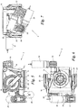
- FIG. 1 Show in the drawings the Figs. 1 and 2 a solar module with fan-out solar panels in two different operating positions, each in a schematic perspective view obliquely from above; the Figures 3 and 4 a pan and fan drive according to the invention for the solar module Figs. 1 and 2 in two different operating positions, once in a perspective view obliquely from above ( Fig. 3 ) and once in a perspective view from diagonally below ( Fig. 4 ); the Figures 5 to 7 the swivel and fan drive of the Figures 3 and 4 in a side view ( Fig. 5 ), a top view ( Fig. 6 ) and a rear view ( Fig. 7 ); and the Figs. 8-11 two variants of an alternative embodiment of the swivel and fan drive Figures 3 to 7 each in two different operating positions on average.
- a solar module 1 is shown with a plurality of lamellar solar panels 2 which are mounted on an anchorage 4 so that they can be swiveled and fanned out via a swivel and fan drive 3.
- the solar panels 2 can thus from a first, in Fig. 1 fanned-in position shown, in which they are essentially congruent in a stack, in a second, in Fig. 2
- the fanned-out position shown in which they are fanned out around a common fanning-out axis 5 and thus essentially lie next to one another, and vice versa.
- the fan axis 5 can be adjusted around a first, essentially vertical axis 6 in azimuth and around a second, essentially horizontal axis 7 in elevation in order to align the fanned out solar panels 2 with the sun and this to track.
- the anchoring 4 can be of any type, for example a stand or tripod as shown, but also a building part, a floor anchoring, a ship part, a vehicle, a container or the like.
- the solar panels 2 have an approximately circular sector shape, preferably with rounded corners ("petal shape") as shown, and complement each other in their fanned out position ( Fig. 2 ) preferred - although not mandatory - to a full circle.
- twelve solar panels 2 are provided, the circular sector angle of which is approximately 30 ° in each case, with the fan-out or pivoting angle of a solar panel 2 relative to its adjacent solar panel 2 is accordingly about 30 °.
- Each solar panel 2 has a planar array of photovoltaic cells 8 on its upper side, e.g. in crystalline or organic form or in thin-film technology.
- the electrical connections and interconnections of the solar panels 2 and solar cells 8 are not shown for the sake of clarity; For example, the solar panels 2 are contacted via flexible connection cables or sliding contacts and rigid contact rings on the anchorage 4 or the swivel and fan drive 3 and connected to the other power transmission electronics.
- the Figures 3 to 9 show the swivel and fan drive 3 for the solar panels 2 in detail.
- the swivel and fan drive 3 comprises a base support 9, here in the form of an annular flange, which can be screwed onto the upper end of the anchoring 4 via bores 10, for example.
- a rotary plate 12 is at least pivotable, preferably fully rotatable, about the axis 6 on the base support 9 via a ball bearing 11.
- the turntable 12 has at its one end 13 two bearing arms 14 which protrude obliquely upwards and are spaced apart from one another, between which one end 15 of a pivot plate 16 is pivotably mounted about the axis 7.
- the pivot plate 16 could also be pivotably mounted on the turntable 12 in another way, for example with the aid of a hinge.
- the terms "turntable” and “swivel plate” do not literally refer to a plate or plate shape, but to its function, i.e. the turntable 12 could also have a shape other than a plate, for example in the form of a hub, a shaft connector, a block, etc .; and the pivot plate 16 could have a shape other than a plate shape, e.g. be a hub, a nozzle, a block or any shaped carrier.
- a fan shaft 18 is at least about the fan axis 5 via a ball bearing 17 pivotable, preferably fully rotatable, mounted. From the fan shaft 18 is in the Figures 3 to 9 only its end part on the drive side, designed as an annular flange, on which, for example via bores 19, the remaining, in Fig. 2 recognizable part of the fan shaft 18 can be flanged, which carries the solar panels 2.
- the solar panels 2 can be moved from the fanned-in position ( Fig. 1 ) to the fanned out position ( Fig. 2 ) and vice versa. For example, the top (or bottom) solar panel 2 of the stack ( Fig.
- the bottom (or top) solar panel 2 is non-rotatably connected to the swivel plate 16, with one of the solar panels 2 dragging the adjacent solar panel 2 along with it by means of drag rails, tow hooks, drivers or the like until all solar panels 2 are fanned out or fanned in.
- each solar panel 2 (with the exception of the lowest solar panel 2) is optionally equipped with a sweeping lip on its back, which sweeps away the respective underlying solar panel 2 when it is fanned out.
- the sweeping lip can be, for example, a rubber lip or a brush lip and at the same time form the drag strip.
- the pivoting plate 16 relative to the turntable 12 is pivoted with the aid of at least one (here: two) cranks 20, which sit on a common shaft 21, which are mounted in bearing tabs 22 of the turntable 12, in such a way that the axis 21 'of Shaft 21 is parallel to and at a distance from the pivot axis 7 of the pivot plate 16.
- the bearing tabs 22 can be formed by the foot regions of the bearing arms 14 or separately therefrom.
- cranks 20 are each at their ends facing away from the shaft 21 via a connecting rod 23 with the end 15 opposite other end 24 of the pivot plate 16 is coupled to a pivot axis 25.
- cranks 20 and connecting rod 23 form a four-bar coupling mechanism, u.zw. more precisely a crank swing gear, the “crank” of which is the cranks 20, the “rocker” of which is the swivel plate 16, the “frame” of which is the turntable 2 and its “coupling member” the connecting rod 23.
- the frame length between shaft axis 21 'and pivot axis 7, the rocker arm length between pivot axis 7 and pivot axis 25, and the effective lengths of crank 20 and connecting rod 23 determine the kinematics of the rocker crank mechanism, as is known in the art.
- the lengths mentioned are preferred - this is not mandatory - selected so that the swivel plate 16 can pivot about 90 ° from an approximately horizontal rest position ( Fig. 3 ) in an approximately vertical end position ( Fig. 4 ) and back when the cranks 20 complete a full revolution.
- the shaft axis 21 'of the cranks 20 is inclined below the pivot axis 7, so that in the rest position ( Fig. 3 ) the pivot plate 16 is approximately parallel to and above the turntable 12 when the cranks 20 and connecting rods 23 are in their maximally shortened position.
- This has a very small footprint in the rest position, see Fig. 3 .
- the cranks 20 and connecting rods 23 are in their maximally extended position.
- the movements of the swivel and fan drive 3 about one or more of the axes 5, 6, 7 can be carried out manually in the simplest case.
- the movements about one or more of the axes 5, 6, 7 are preferably brought about by appropriate drives, for example hydraulic or pneumatic cylinders, servomotors, stepping motors or the like
- Figures 3 to 7 a first embodiment is shown in which a gear-reduced electric drive is provided for each of the three movements.
- a first electric motor 26 with a flange-mounted angular gear 27 is mounted on the turntable 12 and drives one of the cranks 20 or its shaft 21 via a first worm gear 28.
- the first worm gear 28 comprises, for example, a worm driven by the electric motor 26 via the angular gear 27, which engages in a worm wheel seated on a crank 20 or the shaft 21.
- a second electric motor 29 with a flange-mounted angular gear 30 is mounted on the base support 9 and drives the turntable 12 via a second worm gear 31, which has, for example, a worm that engages in a worm wheel of the turntable 12.
- a third electric motor 32 with flange-mounted angular gear 33 is mounted on the swivel plate 16 and drives the fan shaft 18 via a third worm gear 34, for example again with the help of a worm that engages a worm wheel connected to the fan shaft 18.
- suitable other gears e.g. Spur gears, planetary gears or angular gears, such as bevel gears, crown gears or planetary deflection gears, u.zw. each with one or more gear stages can be used.
- a gear shaft 35 with an approximately vertical axis of rotation is supported in bearings 36, 37 on the turntable 12 and / or one of its bearing brackets 22.
- the transmission shaft 35 has a pinion 38 which meshes with a toothed ring 39 which is formed on the outer circumference of a flange 40 of the base support 9.
- the gear shaft 35 carries another pinion 41, which in the pivoted down position of the pivot plate 16 ( Fig. 8 or 10) comes into engagement with a ring gear 42 which is formed on the outer circumference of the fan shaft 18.
- the second electric motor 29 thus drives both the turntable 12 and - via the engagement of pinion 41 and ring gear 42 - the fan shaft 18, so that during the rotation about axis 6, solar panels 2 are simultaneously raised about axis 5. or fanned out.
- the pinion 41 and the ring gear 42 thus form a coupling between the turntable 12 or its drive and the fan shaft 18, which in the Fig. 8 and 10 shown rest position of the pivot plate 16 is closed.
- the coupling opens, see FIG Fig. 9 or 11, ie the pinion 41 and the ring gear 42 disengage, so that the electric motor 29 can now be used again exclusively for the rotary drive about the axis 6, ie the azimuth adjustment of the solar panels 2.
- the stacked solar panels 2 can be pivoted down in the fanned-in position by rotating about the pivot axis 7, so that they the Fig. 1 Take up the shown hanging protection position against wind and weather.
- the first electric motor 26 for the swivel plate drive can also be used for the optional driving of the fan shaft 18, in which case a similar coupling between the swivel plate 16 or its drive 26 and the fan shaft 18 is provided.
- the fan shaft 18 is temporarily fixed in rotation with respect to the swivel plate 16 so that an unintentional change in the fanning-in or fan-out position of the solar panels 2 is avoided, in particular during their azimuth and elevation adjustment.
- the further clutch includes in the variant embodiment Figures 8 and 9 a brake disc 45 connected to the fan shaft 18 in a rotationally fixed manner and preloaded against a braking surface 43 of the pivot plate 16 by means of a spring 44.
- any other type of coupling can also be used which enables the temporary fixing of the fan shaft 18 as shown.
- the braking function of the further clutch can alternatively be achieved by a brake pinion 47 or the like.
- brake teeth 48 which in the position of Fig. 10 approximately in alignment with the gear shaft 35 on the pivot plate 16 in a rotationally fixed but axially movable manner, ie in the illustration of FIG Fig. 10 vertically movable, is mounted loaded down by a spring 49.
- this brake pinion 47 with its brake teeth 48 is spring-loaded into meshing engagement with the ring gear 42 in order to fix it for rotation.
- the rest position of the swivel plate 16 it is from the gear shaft 35 against its spring action pushed out of the meshing engagement and thus releases the ring gear 42.
- clutches 41, 42 and 43-49 could also be operated manually or by means of electrical actuators which e.g. can be controlled by electronics that also control the electric motors 26 and 29 accordingly.
Landscapes
- Engineering & Computer Science (AREA)
- General Engineering & Computer Science (AREA)
- Mechanical Engineering (AREA)
- Life Sciences & Earth Sciences (AREA)
- Sustainable Development (AREA)
- Thermal Sciences (AREA)
- Physics & Mathematics (AREA)
- Sustainable Energy (AREA)
- Chemical & Material Sciences (AREA)
- Combustion & Propulsion (AREA)
- Power Engineering (AREA)
- Photovoltaic Devices (AREA)
- Transmission Devices (AREA)
- Specific Sealing Or Ventilating Devices For Doors And Windows (AREA)
- Structures Of Non-Positive Displacement Pumps (AREA)
- Braking Arrangements (AREA)
Priority Applications (3)
| Application Number | Priority Date | Filing Date | Title |
|---|---|---|---|
| SM20250485T SMT202500485T1 (it) | 2015-10-02 | 2016-09-20 | Azionamento orientabile e a ventaglio per pannelli solari |
| RS20251246A RS67495B1 (sr) | 2015-10-02 | 2016-09-20 | Zakretni i lepezasti pogon za solarne panele |
| HRP20251537TT HRP20251537T1 (hr) | 2015-10-02 | 2016-09-20 | Zakretni i lepezasti pogon za solarne panele |
Applications Claiming Priority (3)
| Application Number | Priority Date | Filing Date | Title |
|---|---|---|---|
| ATA50840/2015A AT517705B1 (de) | 2015-10-02 | 2015-10-02 | Schwenk- und Fächerantrieb für Solarpaneele |
| EP16793730.9A EP3357157B1 (fr) | 2015-10-02 | 2016-09-20 | Entraînement à pivotement et déploiement alement pour des panneaux solaires |
| PCT/AT2016/060067 WO2017054026A1 (fr) | 2015-10-02 | 2016-09-20 | Entraînement à pivotement et déploiement alement pour des panneaux solaires |
Related Parent Applications (1)
| Application Number | Title | Priority Date | Filing Date |
|---|---|---|---|
| EP16793730.9A Division EP3357157B1 (fr) | 2015-10-02 | 2016-09-20 | Entraînement à pivotement et déploiement alement pour des panneaux solaires |
Publications (3)
| Publication Number | Publication Date |
|---|---|
| EP3716471A1 true EP3716471A1 (fr) | 2020-09-30 |
| EP3716471C0 EP3716471C0 (fr) | 2025-09-03 |
| EP3716471B1 EP3716471B1 (fr) | 2025-09-03 |
Family
ID=57256007
Family Applications (5)
| Application Number | Title | Priority Date | Filing Date |
|---|---|---|---|
| EP20164839.1A Withdrawn EP3691117A1 (fr) | 2015-10-02 | 2016-09-20 | Entraînement à pivotement et déploiement pour panneaux solaires |
| EP16793730.9A Active EP3357157B1 (fr) | 2015-10-02 | 2016-09-20 | Entraînement à pivotement et déploiement alement pour des panneaux solaires |
| EP20164840.9A Active EP3716471B1 (fr) | 2015-10-02 | 2016-09-20 | Entraînement à pivotement et déploiement pour panneaux solaires |
| EP20164842.5A Active EP3691118B1 (fr) | 2015-10-02 | 2016-09-20 | Entraînement à pivotement et déploiement pour panneaux solaires |
| EP20164837.5A Withdrawn EP3691116A1 (fr) | 2015-10-02 | 2016-09-20 | Entraînement à pivotement et déploiement pour panneaux solaires |
Family Applications Before (2)
| Application Number | Title | Priority Date | Filing Date |
|---|---|---|---|
| EP20164839.1A Withdrawn EP3691117A1 (fr) | 2015-10-02 | 2016-09-20 | Entraînement à pivotement et déploiement pour panneaux solaires |
| EP16793730.9A Active EP3357157B1 (fr) | 2015-10-02 | 2016-09-20 | Entraînement à pivotement et déploiement alement pour des panneaux solaires |
Family Applications After (2)
| Application Number | Title | Priority Date | Filing Date |
|---|---|---|---|
| EP20164842.5A Active EP3691118B1 (fr) | 2015-10-02 | 2016-09-20 | Entraînement à pivotement et déploiement pour panneaux solaires |
| EP20164837.5A Withdrawn EP3691116A1 (fr) | 2015-10-02 | 2016-09-20 | Entraînement à pivotement et déploiement pour panneaux solaires |
Country Status (21)
| Country | Link |
|---|---|
| US (2) | US10298173B2 (fr) |
| EP (5) | EP3691117A1 (fr) |
| JP (2) | JP6885932B2 (fr) |
| KR (1) | KR102709747B1 (fr) |
| CN (2) | CN111726059B (fr) |
| AT (1) | AT517705B1 (fr) |
| AU (2) | AU2016333140B2 (fr) |
| CL (1) | CL2018000826A1 (fr) |
| DK (1) | DK3357157T3 (fr) |
| ES (3) | ES3057857T3 (fr) |
| HR (1) | HRP20251537T1 (fr) |
| IL (2) | IL258388B (fr) |
| MX (2) | MX2018003917A (fr) |
| PH (1) | PH12018500728A1 (fr) |
| PL (1) | PL3716471T4 (fr) |
| PT (1) | PT3357157T (fr) |
| RS (1) | RS67495B1 (fr) |
| SG (2) | SG10201912476SA (fr) |
| SM (1) | SMT202500485T1 (fr) |
| WO (1) | WO2017054026A1 (fr) |
| ZA (1) | ZA201802077B (fr) |
Families Citing this family (15)
| Publication number | Priority date | Publication date | Assignee | Title |
|---|---|---|---|---|
| AT517705B1 (de) * | 2015-10-02 | 2017-04-15 | Smart Flower Energy Tech Gmbh | Schwenk- und Fächerantrieb für Solarpaneele |
| CN109194269B (zh) * | 2018-10-23 | 2023-10-17 | 西南交通大学 | 一种折叠扇形板的机构 |
| USD909960S1 (en) * | 2018-11-14 | 2021-02-09 | Alexander Swatek | Solar power module |
| CO2018014418A1 (es) * | 2018-12-31 | 2019-01-18 | Arbulu Saavedra Mario Ricardo | Sistema desplegable de paneles solares con mecanismo posicionador para captar la luz solar |
| DE102019003279B4 (de) * | 2019-05-08 | 2021-10-14 | Mbda Deutschland Gmbh | Vorrichtung zum Schwenken eines kippbaren Mastes, Teleskopmastanordnung, Verfahren zum Aufrichten und Verfahren zum Ablegen eines Teleskopmastes |
| MA46073A1 (fr) * | 2019-06-04 | 2020-12-31 | Jilali Toumi | Dispositif porte plaques solaires pour voitures |
| CH717565A1 (fr) * | 2020-06-25 | 2021-12-30 | Planair Sa | Installation photovoltaïque et procédé de construction d'une telle installation. |
| USD1011272S1 (en) * | 2020-07-28 | 2024-01-16 | Palm Energy Systems Llc | Solar collector pillar |
| CN112152556B (zh) * | 2020-08-12 | 2024-09-13 | 常熟理工学院 | 家用自动折叠太阳能面板 |
| US11987976B2 (en) * | 2021-11-10 | 2024-05-21 | Khaled Elbehiery | Rotating building assembly |
| CN114759871A (zh) * | 2022-04-06 | 2022-07-15 | 同辉电子科技股份有限公司 | 一种基于风速监测的太阳能板折叠机构 |
| CN115027306B (zh) * | 2022-07-30 | 2025-08-15 | 山东鼎盛电气设备有限公司 | 一种露天停车场智能太阳能充电桩 |
| TWI833348B (zh) * | 2022-09-12 | 2024-02-21 | 賴彥光 | 樹狀太陽能集電柱及集電系統 |
| USD1073591S1 (en) * | 2023-01-18 | 2025-05-06 | Xiamen Topunive Technology Co., Ltd. | Solar charging pile |
| DE102023124473A1 (de) * | 2023-09-11 | 2025-03-13 | Auma Riester Gmbh & Co. Kg | Stellantrieb und Baugruppe |
Citations (7)
| Publication number | Priority date | Publication date | Assignee | Title |
|---|---|---|---|---|
| ES473356A1 (es) * | 1978-09-14 | 1979-11-01 | Sener Ing & Sist | Perfeccionamientos en heliostatos |
| KR20090037100A (ko) * | 2007-10-11 | 2009-04-15 | 박태선 | 태양광 발전 트래커 |
| WO2011134004A1 (fr) * | 2010-04-27 | 2011-11-03 | Upton Ecoforlife Solar Trackers Pty. Ltd. | Système de poursuite du soleil |
| AT509886A4 (de) * | 2010-06-29 | 2011-12-15 | Alexander Swatek | Solarmodul |
| WO2012073705A1 (fr) * | 2010-11-30 | 2012-06-07 | 株式会社Sp電機 | Dispositif photovoltaïque |
| AT512680B1 (de) | 2012-04-02 | 2014-05-15 | Smart Flower Energy Technology Gmbh | Solarmodul |
| AT513875B1 (de) | 2013-01-23 | 2015-01-15 | Smart Flower Energy Technology Gmbh | Solarmodul |
Family Cites Families (27)
| Publication number | Priority date | Publication date | Assignee | Title |
|---|---|---|---|---|
| BE684729A (fr) * | 1966-11-10 | 1967-01-03 | ||
| DE3131612A1 (de) | 1981-08-10 | 1983-02-24 | Zahnräderfabrik Renk AG, 8900 Augsburg | Getriebe zur positionierung von sonnenenergie-kollektoren |
| US4552438A (en) * | 1984-01-09 | 1985-11-12 | The United States Of America As Represented By The United States Department Of Energy | Cable tensioned membrane solar collector module with variable tension control |
| US5517204A (en) * | 1992-03-10 | 1996-05-14 | Tokimec Inc. | Antenna directing apparatus |
| JP2002081760A (ja) | 2000-09-08 | 2002-03-22 | Mitsui Eng & Shipbuild Co Ltd | 太陽エネルギー利用システム |
| DE20200609U1 (de) * | 2002-01-16 | 2003-06-05 | Robert Bosch Gmbh, 70469 Stuttgart | Mobile Solar-Akku-Ladestation |
| EP2019936B1 (fr) | 2006-05-24 | 2010-04-21 | Flender Tübingen GmbH | Structure a commande biaxiale |
| US8381718B1 (en) * | 2006-10-20 | 2013-02-26 | Idealab | Actuator for controlling rotation about two axes using a single motor |
| US7878192B2 (en) * | 2006-11-22 | 2011-02-01 | Theodore Edward Larsen | Adjustable solar collector and method of use |
| KR100891500B1 (ko) | 2007-09-11 | 2009-04-06 | 성재욱 | 무인 자동설비용 금형장치 |
| US9214892B2 (en) * | 2007-11-21 | 2015-12-15 | Orbital Atk, Inc. | Solar arrays |
| US8168883B2 (en) * | 2008-05-29 | 2012-05-01 | Moses Clark | Adjustable solar powerer |
| WO2010039999A2 (fr) * | 2008-10-01 | 2010-04-08 | Steven Polk | Collecteur solaire |
| GB2469344B (en) * | 2009-07-23 | 2011-08-24 | Iain Chapman | Moveable mounting |
| US8168931B1 (en) * | 2009-12-09 | 2012-05-01 | Concrete Systems, Inc. | Solar tracking device |
| KR101187925B1 (ko) * | 2010-04-06 | 2012-10-05 | 박용우 | 한 개의 모터로 2축 구동이 가능한 태양광발전용 추적시스템 |
| US20110277748A1 (en) * | 2010-05-12 | 2011-11-17 | Raymond Chu | Closable Solar Collector |
| MA34337B1 (fr) * | 2011-02-22 | 2013-06-01 | Sunpower Corp | Entrainement de suiveur solaire |
| US9443999B2 (en) * | 2011-04-07 | 2016-09-13 | Steven Polk | Solar energy collector |
| US20120285506A1 (en) * | 2011-05-13 | 2012-11-15 | Chieh-Hsing Kuo | Solar Tracker |
| JP6040242B2 (ja) * | 2011-08-15 | 2016-12-07 | モーガン ソーラー インコーポレーテッド | 自己安定型の太陽光追尾装置 |
| DE102012021106A1 (de) * | 2012-02-17 | 2013-08-22 | Heidelberger Druckmaschinen Ag | Vorrichtung für den Einsatz in Systemen zur Nutzung von Solarenergie |
| KR101304647B1 (ko) * | 2012-11-24 | 2013-09-06 | 류지연 | 태양추적장치 및 그 운영방법 |
| FR3011149B1 (fr) * | 2013-09-26 | 2019-03-15 | Servitronique | Dispositif de reglage a 2 axes d'une partie d'installation en particulier d'un ou plusieurs panneaux solaires |
| CN104156005B (zh) * | 2014-08-07 | 2017-10-24 | 福建农林大学 | 一种太阳能追光装置 |
| CN104539230A (zh) * | 2014-12-26 | 2015-04-22 | 金海新源电气江苏有限公司 | 一种光伏太阳能旋转支架 |
| AT517705B1 (de) | 2015-10-02 | 2017-04-15 | Smart Flower Energy Tech Gmbh | Schwenk- und Fächerantrieb für Solarpaneele |
-
2015
- 2015-10-02 AT ATA50840/2015A patent/AT517705B1/de active
-
2016
- 2016-09-20 EP EP20164839.1A patent/EP3691117A1/fr not_active Withdrawn
- 2016-09-20 EP EP16793730.9A patent/EP3357157B1/fr active Active
- 2016-09-20 SG SG10201912476SA patent/SG10201912476SA/en unknown
- 2016-09-20 US US15/764,365 patent/US10298173B2/en active Active
- 2016-09-20 ES ES20164840T patent/ES3057857T3/es active Active
- 2016-09-20 AU AU2016333140A patent/AU2016333140B2/en active Active
- 2016-09-20 PT PT167937309T patent/PT3357157T/pt unknown
- 2016-09-20 HR HRP20251537TT patent/HRP20251537T1/hr unknown
- 2016-09-20 JP JP2018517205A patent/JP6885932B2/ja active Active
- 2016-09-20 CN CN202010499948.1A patent/CN111726059B/zh active Active
- 2016-09-20 PL PL20164840.9T patent/PL3716471T4/pl unknown
- 2016-09-20 CN CN201680062887.4A patent/CN108391461B/zh active Active
- 2016-09-20 SM SM20250485T patent/SMT202500485T1/it unknown
- 2016-09-20 KR KR1020187011611A patent/KR102709747B1/ko active Active
- 2016-09-20 DK DK16793730.9T patent/DK3357157T3/da active
- 2016-09-20 EP EP20164840.9A patent/EP3716471B1/fr active Active
- 2016-09-20 WO PCT/AT2016/060067 patent/WO2017054026A1/fr not_active Ceased
- 2016-09-20 MX MX2018003917A patent/MX2018003917A/es unknown
- 2016-09-20 RS RS20251246A patent/RS67495B1/sr unknown
- 2016-09-20 ES ES16793730T patent/ES2811324T3/es active Active
- 2016-09-20 SG SG11201802664SA patent/SG11201802664SA/en unknown
- 2016-09-20 ES ES20164842T patent/ES3009007T3/es active Active
- 2016-09-20 EP EP20164842.5A patent/EP3691118B1/fr active Active
- 2016-09-20 EP EP20164837.5A patent/EP3691116A1/fr not_active Withdrawn
-
2018
- 2018-03-27 IL IL258388A patent/IL258388B/en unknown
- 2018-03-28 ZA ZA2018/02077A patent/ZA201802077B/en unknown
- 2018-03-28 MX MX2023003907A patent/MX2023003907A/es unknown
- 2018-03-29 CL CL2018000826A patent/CL2018000826A1/es unknown
- 2018-04-02 PH PH12018500728A patent/PH12018500728A1/en unknown
-
2019
- 2019-02-13 US US16/274,633 patent/US10454410B2/en active Active
-
2021
- 2021-05-13 JP JP2021081696A patent/JP7127189B2/ja active Active
- 2021-07-27 IL IL285159A patent/IL285159B/en unknown
-
2022
- 2022-04-29 AU AU2022202838A patent/AU2022202838B2/en active Active
Patent Citations (8)
| Publication number | Priority date | Publication date | Assignee | Title |
|---|---|---|---|---|
| ES473356A1 (es) * | 1978-09-14 | 1979-11-01 | Sener Ing & Sist | Perfeccionamientos en heliostatos |
| KR20090037100A (ko) * | 2007-10-11 | 2009-04-15 | 박태선 | 태양광 발전 트래커 |
| WO2011134004A1 (fr) * | 2010-04-27 | 2011-11-03 | Upton Ecoforlife Solar Trackers Pty. Ltd. | Système de poursuite du soleil |
| AT509886A4 (de) * | 2010-06-29 | 2011-12-15 | Alexander Swatek | Solarmodul |
| AT509886B1 (de) | 2010-06-29 | 2011-12-15 | Alexander Swatek | Solarmodul |
| WO2012073705A1 (fr) * | 2010-11-30 | 2012-06-07 | 株式会社Sp電機 | Dispositif photovoltaïque |
| AT512680B1 (de) | 2012-04-02 | 2014-05-15 | Smart Flower Energy Technology Gmbh | Solarmodul |
| AT513875B1 (de) | 2013-01-23 | 2015-01-15 | Smart Flower Energy Technology Gmbh | Solarmodul |
Also Published As
Similar Documents
| Publication | Publication Date | Title |
|---|---|---|
| EP3691118B1 (fr) | Entraînement à pivotement et déploiement pour panneaux solaires | |
| EP2949038B1 (fr) | Module solaire | |
| AT509886B1 (de) | Solarmodul | |
| AT512680B1 (de) | Solarmodul | |
| DE102005014320A1 (de) | Nachführeinrichtung für eine Photovoltaikanlage | |
| DE102009034144A1 (de) | Nachführeinrichtung für eine Photovoltaikanlage | |
| EP2663720A1 (fr) | Agencement de volet pliant comprenant plusieurs éléments rigides dotes, en particulier, de bords infléchissants et non infléchissants en alternance | |
| EP1788322A1 (fr) | Monture pour un groupe de modules solaires | |
| DE102016123372A1 (de) | Kameraarm | |
| DE202008015767U1 (de) | Nachführungseinrichtung für plattenförmige Solarmodule | |
| DE102014002588A1 (de) | Radial raffbares Membrandach | |
| EP2038589A1 (fr) | Dispositif de poursuite pour capteurs solaires | |
| DE102009022876A1 (de) | Nachführeinheit sowie Sonnenkollektor- oder Photovoltaikeinheit | |
| DE102016008737B4 (de) | Kamerawagen | |
| DE3918184A1 (de) | Windrad | |
| DE3029502A1 (de) | Heuwerbungsmaschine | |
| DE202006005881U1 (de) | Vorrichtung zur Nachführung von Solarzellen | |
| EP1063707A2 (fr) | Panneau de cellules solaires | |
| WO2026021919A1 (fr) | Installation de centrale solaire | |
| DE202020106700U1 (de) | Footballtor | |
| DE8317459U1 (de) | Fahrgeschaeft | |
| EP3284947A1 (fr) | Éolienne et procede de montage d'une eolienne | |
| DE102017011944A1 (de) | Kamerawagen | |
| DE4425053A1 (de) | Für oder Fenster |
Legal Events
| Date | Code | Title | Description |
|---|---|---|---|
| REG | Reference to a national code |
Ref country code: HR Ref legal event code: TUEP Ref document number: P20251537T Country of ref document: HR |
|
| PUAI | Public reference made under article 153(3) epc to a published international application that has entered the european phase |
Free format text: ORIGINAL CODE: 0009012 |
|
| STAA | Information on the status of an ep patent application or granted ep patent |
Free format text: STATUS: THE APPLICATION HAS BEEN PUBLISHED |
|
| AC | Divisional application: reference to earlier application |
Ref document number: 3357157 Country of ref document: EP Kind code of ref document: P |
|
| AK | Designated contracting states |
Kind code of ref document: A1 Designated state(s): AL AT BE BG CH CY CZ DE DK EE ES FI FR GB GR HR HU IE IS IT LI LT LU LV MC MK MT NL NO PL PT RO RS SE SI SK SM TR |
|
| STAA | Information on the status of an ep patent application or granted ep patent |
Free format text: STATUS: REQUEST FOR EXAMINATION WAS MADE |
|
| 17P | Request for examination filed |
Effective date: 20210301 |
|
| RBV | Designated contracting states (corrected) |
Designated state(s): AL AT BE BG CH CY CZ DE DK EE ES FI FR GB GR HR HU IE IS IT LI LT LU LV MC MK MT NL NO PL PT RO RS SE SI SK SM TR |
|
| STAA | Information on the status of an ep patent application or granted ep patent |
Free format text: STATUS: EXAMINATION IS IN PROGRESS |
|
| 17Q | First examination report despatched |
Effective date: 20230202 |
|
| REG | Reference to a national code |
Ref country code: DE Ref legal event code: R079 Free format text: PREVIOUS MAIN CLASS: H02S0020300000 Ipc: H02S0030200000 Ref document number: 502016017073 Country of ref document: DE |
|
| GRAP | Despatch of communication of intention to grant a patent |
Free format text: ORIGINAL CODE: EPIDOSNIGR1 |
|
| STAA | Information on the status of an ep patent application or granted ep patent |
Free format text: STATUS: GRANT OF PATENT IS INTENDED |
|
| RIC1 | Information provided on ipc code assigned before grant |
Ipc: F24S 20/50 20180101ALI20250311BHEP Ipc: H02S 20/30 20140101ALI20250311BHEP Ipc: H02S 30/20 20140101AFI20250311BHEP |
|
| INTG | Intention to grant announced |
Effective date: 20250324 |
|
| GRAS | Grant fee paid |
Free format text: ORIGINAL CODE: EPIDOSNIGR3 |
|
| GRAA | (expected) grant |
Free format text: ORIGINAL CODE: 0009210 |
|
| STAA | Information on the status of an ep patent application or granted ep patent |
Free format text: STATUS: THE PATENT HAS BEEN GRANTED |
|
| AC | Divisional application: reference to earlier application |
Ref document number: 3357157 Country of ref document: EP Kind code of ref document: P |
|
| AK | Designated contracting states |
Kind code of ref document: B1 Designated state(s): AL AT BE BG CH CY CZ DE DK EE ES FI FR GB GR HR HU IE IS IT LI LT LU LV MC MK MT NL NO PL PT RO RS SE SI SK SM TR |
|
| REG | Reference to a national code |
Ref country code: CH Ref legal event code: EP |
|
| REG | Reference to a national code |
Ref country code: DE Ref legal event code: R096 Ref document number: 502016017073 Country of ref document: DE |
|
| REG | Reference to a national code |
Ref country code: IE Ref legal event code: FG4D Free format text: LANGUAGE OF EP DOCUMENT: GERMAN |
|
| U01 | Request for unitary effect filed |
Effective date: 20251001 |
|
| U07 | Unitary effect registered |
Designated state(s): AT BE BG DE DK EE FI FR IT LT LU LV MT NL PT RO SE SI Effective date: 20251010 |
|
| REG | Reference to a national code |
Ref country code: CH Ref legal event code: R17 Free format text: ST27 STATUS EVENT CODE: U-0-0-R10-R17 (AS PROVIDED BY THE NATIONAL OFFICE) Effective date: 20251203 |
|
| U20 | Renewal fee for the european patent with unitary effect paid |
Year of fee payment: 10 Effective date: 20251027 |
|
| REG | Reference to a national code |
Ref country code: CH Ref legal event code: U11 Free format text: ST27 STATUS EVENT CODE: U-0-0-U10-U11 (AS PROVIDED BY THE NATIONAL OFFICE) Effective date: 20251229 |
|
| PGFP | Annual fee paid to national office [announced via postgrant information from national office to epo] |
Ref country code: GB Payment date: 20251229 Year of fee payment: 10 |
|
| PGFP | Annual fee paid to national office [announced via postgrant information from national office to epo] |
Ref country code: GR Payment date: 20251230 Year of fee payment: 10 |
|
| PGFP | Annual fee paid to national office [announced via postgrant information from national office to epo] |
Ref country code: CH Payment date: 20251229 Year of fee payment: 10 |
|
| REG | Reference to a national code |
Ref country code: GR Ref legal event code: EP Ref document number: 20250402516 Country of ref document: GR Effective date: 20260115 |
|
| PGFP | Annual fee paid to national office [announced via postgrant information from national office to epo] |
Ref country code: IE Payment date: 20251229 Year of fee payment: 10 |
|
| REG | Reference to a national code |
Ref country code: HR Ref legal event code: ODRP Ref document number: P20251537T Country of ref document: HR Payment date: 20260113 Year of fee payment: 10 |
|
| REG | Reference to a national code |
Ref country code: HR Ref legal event code: T1PR Ref document number: P20251537 Country of ref document: HR |
|
| PGFP | Annual fee paid to national office [announced via postgrant information from national office to epo] |
Ref country code: HU Payment date: 20260109 Year of fee payment: 10 |
|
| REG | Reference to a national code |
Ref country code: ES Ref legal event code: FG2A Ref document number: 3057857 Country of ref document: ES Kind code of ref document: T3 Effective date: 20260305 |
|
| REG | Reference to a national code |
Ref country code: SK Ref legal event code: T3 Ref document number: E 47864 Country of ref document: SK |
|
| PGFP | Annual fee paid to national office [announced via postgrant information from national office to epo] |
Ref country code: SM Payment date: 20260112 Year of fee payment: 10 |
|
| PGFP | Annual fee paid to national office [announced via postgrant information from national office to epo] |
Ref country code: MC Payment date: 20260105 Year of fee payment: 10 Ref country code: ES Payment date: 20260102 Year of fee payment: 10 |
|
| PGFP | Annual fee paid to national office [announced via postgrant information from national office to epo] |
Ref country code: NO Payment date: 20260128 Year of fee payment: 10 |
|
| PGFP | Annual fee paid to national office [announced via postgrant information from national office to epo] |
Ref country code: HR Payment date: 20260113 Year of fee payment: 10 |
|
| PGFP | Annual fee paid to national office [announced via postgrant information from national office to epo] |
Ref country code: RS Payment date: 20260103 Year of fee payment: 10 |
|
| PGFP | Annual fee paid to national office [announced via postgrant information from national office to epo] |
Ref country code: IS Payment date: 20260113 Year of fee payment: 10 |
|
| PGFP | Annual fee paid to national office [announced via postgrant information from national office to epo] |
Ref country code: TR Payment date: 20260102 Year of fee payment: 10 |