EP3717143B1 - Cage de laminage - Google Patents
Cage de laminage Download PDFInfo
- Publication number
- EP3717143B1 EP3717143B1 EP18804581.9A EP18804581A EP3717143B1 EP 3717143 B1 EP3717143 B1 EP 3717143B1 EP 18804581 A EP18804581 A EP 18804581A EP 3717143 B1 EP3717143 B1 EP 3717143B1
- Authority
- EP
- European Patent Office
- Prior art keywords
- stand
- roll stand
- rolling
- sides
- roll
- Prior art date
- Legal status (The legal status is an assumption and is not a legal conclusion. Google has not performed a legal analysis and makes no representation as to the accuracy of the status listed.)
- Active
Links
Images

Classifications
-
- B—PERFORMING OPERATIONS; TRANSPORTING
- B21—MECHANICAL METAL-WORKING WITHOUT ESSENTIALLY REMOVING MATERIAL; PUNCHING METAL
- B21B—ROLLING OF METAL
- B21B21/00—Pilgrim-step tube-rolling, i.e. pilger mills
-
- B—PERFORMING OPERATIONS; TRANSPORTING
- B22—CASTING; POWDER METALLURGY
- B22F—WORKING METALLIC POWDER; MANUFACTURE OF ARTICLES FROM METALLIC POWDER; MAKING METALLIC POWDER; APPARATUS OR DEVICES SPECIALLY ADAPTED FOR METALLIC POWDER
- B22F10/00—Additive manufacturing of workpieces or articles from metallic powder
- B22F10/80—Data acquisition or data processing
- B22F10/85—Data acquisition or data processing for controlling or regulating additive manufacturing processes
-
- B—PERFORMING OPERATIONS; TRANSPORTING
- B22—CASTING; POWDER METALLURGY
- B22F—WORKING METALLIC POWDER; MANUFACTURE OF ARTICLES FROM METALLIC POWDER; MAKING METALLIC POWDER; APPARATUS OR DEVICES SPECIALLY ADAPTED FOR METALLIC POWDER
- B22F5/00—Manufacture of workpieces or articles from metallic powder characterised by the special shape of the product
- B22F5/008—Manufacture of workpieces or articles from metallic powder characterised by the special shape of the product of engine cylinder parts or of piston parts other than piston rings
-
- G—PHYSICS
- G06—COMPUTING OR CALCULATING; COUNTING
- G06F—ELECTRIC DIGITAL DATA PROCESSING
- G06F30/00—Computer-aided design [CAD]
- G06F30/20—Design optimisation, verification or simulation
- G06F30/23—Design optimisation, verification or simulation using finite element methods [FEM] or finite difference methods [FDM]
-
- B—PERFORMING OPERATIONS; TRANSPORTING
- B21—MECHANICAL METAL-WORKING WITHOUT ESSENTIALLY REMOVING MATERIAL; PUNCHING METAL
- B21B—ROLLING OF METAL
- B21B13/00—Metal-rolling stands, i.e. an assembly composed of a stand frame, rolls, and accessories
-
- B—PERFORMING OPERATIONS; TRANSPORTING
- B22—CASTING; POWDER METALLURGY
- B22F—WORKING METALLIC POWDER; MANUFACTURE OF ARTICLES FROM METALLIC POWDER; MAKING METALLIC POWDER; APPARATUS OR DEVICES SPECIALLY ADAPTED FOR METALLIC POWDER
- B22F10/00—Additive manufacturing of workpieces or articles from metallic powder
- B22F10/20—Direct sintering or melting
-
- B—PERFORMING OPERATIONS; TRANSPORTING
- B33—ADDITIVE MANUFACTURING TECHNOLOGY
- B33Y—ADDITIVE MANUFACTURING, i.e. MANUFACTURING OF THREE-DIMENSIONAL [3D] OBJECTS BY ADDITIVE DEPOSITION, ADDITIVE AGGLOMERATION OR ADDITIVE LAYERING, e.g. BY 3D PRINTING, STEREOLITHOGRAPHY OR SELECTIVE LASER SINTERING
- B33Y10/00—Processes of additive manufacturing
-
- B—PERFORMING OPERATIONS; TRANSPORTING
- B33—ADDITIVE MANUFACTURING TECHNOLOGY
- B33Y—ADDITIVE MANUFACTURING, i.e. MANUFACTURING OF THREE-DIMENSIONAL [3D] OBJECTS BY ADDITIVE DEPOSITION, ADDITIVE AGGLOMERATION OR ADDITIVE LAYERING, e.g. BY 3D PRINTING, STEREOLITHOGRAPHY OR SELECTIVE LASER SINTERING
- B33Y80/00—Products made by additive manufacturing
Definitions
- the invention relates to a rolling stand according to the preamble of claim 1 and a method for improving an existing rolling mill.
- a rolling mill is made up of two roll stands or sides that are connected to each other by means of mounted spacer bolts. In such a cold pilger rolling mill, the rolling mill is not stationary, but is moved alternately by means of a drive.
- additive manufacturing is understood to mean that, according to the principle of "3D printing", a form or shape definition given as a data set is successively built up by adding tiny amounts of material.
- a roller is understood in particular as a unit that is rotatably mounted in the rolling stand and also comprises a tool surface for carrying out the rolling process.
- a roller can consist of a roller shaft and a roller body mounted thereon. be designed as a tool.
- the roller body can preferably be designed as a replaceable component.
- the connection to the roller shaft can particularly preferably be made by shrinking the roller body onto the roller shaft.
- the rolling stand is partially formed directly by additive manufacturing. This allows maximum flexibility in shaping, whereby the material used must be compatible with the additive process.
- parts of the rolling mill that are less critical in terms of strength and/or weight can consist of conventional components, in particular standard semi-finished products such as plates.
- the invention relates to rolling stands made of an iron-based material with a total mass of more than 0.5 tons.
- the rolling stand is generally advantageous for the rolling stand to be designed as a movable unit that can be driven during a rolling process. It can particularly preferably be a cold pilger rolling stand.
- the achievable speed of the rolling process depends primarily on the mass and strength of the rolling stand, so that a rolling stand optimized according to the invention allows an increase in throughput.
- crank pin is accommodated on the rolling stand for moving the rolling stand, wherein the crank pin is particularly preferably not formed by means of additive manufacturing.
- the crank pin is particularly preferably not formed by means of additive manufacturing.
- the crank pin can also be formed by means of additive manufacturing.
- the rolling stand comprises two sides, with the rollers running between the sides and being mounted in the sides.
- the sides of the stand are connected to one another in one piece using cross struts made of the same material, with the cross struts being manufactured together with the sides of the stand using additive manufacturing. This allows the rolling stand to be particularly rigid while being lightweight.
- a shape of the rolling stand is optimized in terms of mass and/or strength by means of computer optimization using the finite element method. This allows an ideal combination with the advantages of additive manufacturing.
- the new rolling stand can be lighter and/or stronger than the existing rolling stand through appropriate optimization, so that after replacing the rolling stands, for example, a higher stroke frequency can be used. This allows the productivity of existing plants to be improved at relatively low cost.
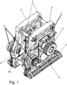
- the previously known rolling stand of a cold pilger rolling device shown comprises two stand sides 1', 2', which are assembled into a stand by a number of separate connecting bolts 3.
- the rolling stand can be driven as a whole, with holding members for movable mounting on a stationary rail system (not shown) being provided in a lower area.
- connecting rods of a drive unit engage bearings 5.
- the bearings 5 are accommodated on crank pins 6, which in turn are fixed in receptacles 6a in the stand sides 1', 2'.
- the connecting rods the rolling stand is moved alternately in a translational manner at a certain stroke frequency.
- At least two rollers 7, 8 are accommodated or mounted in the stand sides 1', 2'. A rotation of the two rollers 7, 8 is coupled to the translational movement of the roll stand via gears 9 and stationary racks (not shown).
- a tubular workpiece (not shown) runs between the rollers 7, 8 and over a mandrel (not shown).
- the alternating movement of the rolling stand in conjunction with a corresponding guide of the workpiece results in a known forming process using the cold pilger rolling process.
- the rolling force occurring between the rollers 7, 8 is supported by the rolling stand 1', 2', 3.
- the previously known rolling stand 1', 2', 3 (without rolls and other fittings) has a mass of about 890 kg.
- the alternating movement takes place with a maximum stroke frequency of 200 strokes per minute.
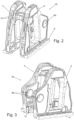
- Fig. 2 to Fig. 5 show a rolling stand 10 made of cast iron according to the invention.
- the shape of this rolling stand 10 was optimized on a computer using the finite element method in order to minimize the mass of the stand for a given strength.
- the starting point for the optimization was known framework data for the dimensions and minimum strengths of the previously known rolling stand 1', 2', 3.
- the shape of the stand was then optimized using the finite element method.
- One criterion for the optimization was that the stand should in principle be castable, and that there should be almost complete freedom of design when producing the casting mold with regard to undercuts, etc.
- the achievable stroke frequency was increased to 250 strokes per minute. This required a reinforced design, particularly in the areas around the crank pins 6.
- the production of the calculated scaffold according to Fig. 2 to Fig. 5 is then carried out via indirect additive manufacturing.
- the casting mold is produced by a 3D printing system using additive manufacturing.
- the rolling stand 10 is then cast using this additively manufactured casting mold. In this case, cast iron is used as the casting material.
- the rolling stand 10 manufactured in this way has a mass of around 800 kg and increased strength despite the stroke frequency being increased to 250 strokes per minute.
- the existing rolling mill Fig. 1
- the stand 1, 2, 3 shown in the figure of an existing rolling mill in operation is replaced by the new stand 10. Due to the reduced stand mass, this generally allows the stroke frequency of the rolling mill to be increased without the need for major changes to the drive device.
- crank pins 6 are also provided as separate components in the additively manufactured rolling stand 10, which are fixed in holders 6a. These crank pins and their holders 6a are among the areas of the rolling stand that are subject to the most mechanical stress.
- the shape determined by the finite element method results in a bionic shape of the rolling stand 10 with many rounded areas. In particular, critical areas such as the area around the holders 6a of the crank pins 6 are relatively reinforced. In less critical areas, the frame material could be relatively thinned out and saved.
- the stand sides 1, 2 of the rolling stand 10 are connected by means of cross struts 11 made of the same material as one piece.
- the cross struts 11 are connected together with the Framework sides 1, 2 manufactured by (indirect) additive manufacturing or by the casting process.
- the rollers 7, 8 are understood here as a unit that is rotatably received in the rolling stand 10 and is formed from a roller shaft and a roller body (not shown) attached thereto.
- a tool surface for carrying out the rolling process is formed by the roller body as a tool.
- the roller body is designed as an exchangeable component.
- the connection to the roller shaft is made here by shrinking the roller body onto the roller shaft. When the roller body is released from the roller shaft, the roller shaft can be removed from the side of the rolling stand 10. Separating the stand sides 1, 2 is therefore not necessary.
- the rolling stand described above can also be manufactured according to the invention by direct additive manufacturing.
- the properties of the additively assembled framework material must be taken into account accordingly in the calculated shaping.
Landscapes
- Engineering & Computer Science (AREA)
- Materials Engineering (AREA)
- Chemical & Material Sciences (AREA)
- Manufacturing & Machinery (AREA)
- Mechanical Engineering (AREA)
- Theoretical Computer Science (AREA)
- Physics & Mathematics (AREA)
- Computer Hardware Design (AREA)
- Geometry (AREA)
- General Engineering & Computer Science (AREA)
- General Physics & Mathematics (AREA)
- Evolutionary Computation (AREA)
- Metal Rolling (AREA)
- Reduction Rolling/Reduction Stand/Operation Of Reduction Machine (AREA)
- Bending Of Plates, Rods, And Pipes (AREA)
Claims (6)
- Châssis de laminoir (10), dans lequel au moins deux rouleaux (7, 8) pour la transformation d'une pièce sont montés dans le châssis, etdans lequel une force de laminage agissant lors de la transformation est supportée par le châssis de laminoir (10),caractérisé en ce quele châssis de laminoir (10) est partiellement formé directement par fabrication additive,le châssis de laminoir (10) comprenant deux côtés de châssis (1, 2), les rouleaux (7, 8) s'étendant entre les côtés de châssis (1, 2) et étant montés dans les côtés de châssis (1, 2), etles côtés de châssis (1, 2) étant reliés de manière monobloc par des entretoises transversales (11), les entretoises transversales (11) étant fabriquées conjointement avec les côtés de châssis (1, 2) par fabrication additive.
- Châssis de laminoir (10) selon la revendication 1, caractérisé en ce que le châssis de laminoir (10) est conçu comme une unité mobile entraînable lors d'un processus de laminage.
- Châssis de laminoir selon la revendication 2, caractérisé en ce que le châssis de laminoir (10) est conçu comme un châssis de laminoir à froid.
- Châssis de laminoir selon la revendication 3, caractérisé en ce qu'au moins un maneton (6) est monté sur le châssis de laminoir (10) pour déplacer le châssis de laminoir (10), le maneton (6) n'étant notamment pas formé par fabrication additive.
- Châssis de laminoir selon l'une des revendications précédentes, caractérisé en ce qu'une forme du châssis de laminoir est optimisée en termes de masse et/ou de résistance par une optimisation informatique utilisant la méthode des éléments finis.
- Procédé d'amélioration d'une installation de laminage existante, comprenant les étapes suivantes :a. enregistrement des paramètres de cadre d'un châssis de laminoir existant (1, 2, 3) ;b. conception d'un châssis de laminoir (10) optimisé en termes de masse et/ou de résistance, en respectant les paramètres de cadre enregistrés à l'étape a ;c. fabrication d'un nouveau châssis de laminoir (10) par fabrication additive selon l'une des revendications précédentes ;d. remplacement du châssis de laminoir existant (1, 2, 3) par le nouveau châssis de laminoir (10).
Applications Claiming Priority (2)
| Application Number | Priority Date | Filing Date | Title |
|---|---|---|---|
| DE102017221126.1A DE102017221126A1 (de) | 2017-11-27 | 2017-11-27 | Walzgerüst |
| PCT/EP2018/081447 WO2019101628A1 (fr) | 2017-11-27 | 2018-11-15 | Cage de laminage |
Publications (3)
| Publication Number | Publication Date |
|---|---|
| EP3717143A1 EP3717143A1 (fr) | 2020-10-07 |
| EP3717143C0 EP3717143C0 (fr) | 2024-10-16 |
| EP3717143B1 true EP3717143B1 (fr) | 2024-10-16 |
Family
ID=64362529
Family Applications (1)
| Application Number | Title | Priority Date | Filing Date |
|---|---|---|---|
| EP18804581.9A Active EP3717143B1 (fr) | 2017-11-27 | 2018-11-15 | Cage de laminage |
Country Status (11)
| Country | Link |
|---|---|
| US (1) | US11534827B2 (fr) |
| EP (1) | EP3717143B1 (fr) |
| JP (1) | JP6945740B2 (fr) |
| CN (1) | CN111295249A (fr) |
| CA (1) | CA3081930C (fr) |
| DE (1) | DE102017221126A1 (fr) |
| MX (1) | MX2020005350A (fr) |
| MY (1) | MY206834A (fr) |
| RU (1) | RU2748306C1 (fr) |
| UA (1) | UA127659C2 (fr) |
| WO (1) | WO2019101628A1 (fr) |
Families Citing this family (1)
| Publication number | Priority date | Publication date | Assignee | Title |
|---|---|---|---|---|
| DE102020206223A1 (de) * | 2020-05-18 | 2021-11-18 | Sms Group Gmbh | Querhaupt zur Verwendung als Ober- und/oder Unterholm in einer Presse |
Citations (3)
| Publication number | Priority date | Publication date | Assignee | Title |
|---|---|---|---|---|
| DE29980239U1 (de) * | 1999-03-04 | 2001-11-29 | Zhao, Linzhen, Zhengzhou, Province Henan | Walzwerk mit zweidimensional gesteuerter Walzendurchbiegung |
| WO2014160695A1 (fr) * | 2013-03-28 | 2014-10-02 | United Technologies Corporation | Fabrication d'élément de turbine à gaz |
| WO2016149774A1 (fr) * | 2015-03-26 | 2016-09-29 | Atlas Copco Airpower, Naamloze Vennootschap | Procédé de fabrication d'une turbine métallique centrifuge et turbine centrifuge obtenue à l'aide dudit procédé |
Family Cites Families (32)
| Publication number | Priority date | Publication date | Assignee | Title |
|---|---|---|---|---|
| DE1287541B (de) | 1964-04-13 | 1969-01-23 | Mannesmann Meer Ag | Walzengeruest fuer Mehrfach-Kaltpilgerwalzwerk |
| US3600913A (en) * | 1968-09-04 | 1971-08-24 | Wean Ind Inc | Pilger mill die adjustment |
| JPS5419455A (en) * | 1977-07-15 | 1979-02-14 | Nippon Steel Corp | Pilger rolling control apparatus |
| SU865442A1 (ru) * | 1980-03-20 | 1981-09-23 | Магнитогорский горно-металлургический институт им. Г.И.Носова | Прокатна клеть с многовалковым калибром |
| JPH0224481Y2 (fr) * | 1985-03-29 | 1990-07-05 | ||
| US4993251A (en) * | 1989-07-07 | 1991-02-19 | Sandvik Special Metals Corporation | Rollstand having easily replaceable roll dies |
| KR100325380B1 (ko) * | 1996-10-09 | 2002-06-26 | 고이치 야나가와 | 미끄럼방지구및미끄럼방지구부착타이어 |
| JP2876121B1 (ja) * | 1998-01-20 | 1999-03-31 | 川崎重工業株式会社 | 圧延機 |
| AT410904B (de) * | 2001-03-14 | 2003-08-25 | Voest Alpine Ind Anlagen | Verfahren und vorrichtung zur berechnung der walzspaltkontur |
| JP2003088908A (ja) * | 2001-09-18 | 2003-03-25 | Sanyo Special Steel Co Ltd | ロールダイス芯出治具 |
| EP1534451B1 (fr) * | 2002-08-20 | 2007-02-14 | Ex One Corporation | Procede de coulee |
| JP2004211162A (ja) * | 2002-12-27 | 2004-07-29 | Jkb:Kk | プレス用金型の製造方法 |
| CN1201879C (zh) * | 2003-04-04 | 2005-05-18 | 太原市通泽成套设备有限公司 | 锥形穿孔机 |
| US20040254665A1 (en) * | 2003-06-10 | 2004-12-16 | Fink Jeffrey E. | Optimal dimensional and mechanical properties of laser sintered hardware by thermal analysis and parameter optimization |
| AT511463B1 (de) * | 2011-06-22 | 2012-12-15 | Siemens Vai Metals Tech Gmbh | Bandbehandlungsvorrichtung |
| CN202683599U (zh) * | 2012-05-04 | 2013-01-23 | 中国重型机械研究院有限公司 | 一种整体机架式四六辊平整机 |
| CN108500184A (zh) * | 2013-07-10 | 2018-09-07 | 奥科宁克有限公司 | 用于制作锻造产品和其他加工产品的方法 |
| TWI497242B (zh) * | 2014-04-11 | 2015-08-21 | Ind Tech Res Inst | 工具機之設計方法及設計系統 |
| JP6479052B2 (ja) * | 2014-05-27 | 2019-03-06 | カーエス コルベンシュミット ゲゼルシャフト ミット ベシュレンクテル ハフツングKS Kolbenschmidt GmbH | 重力金型鋳造のレーザ溶融(sls)の際の積層式の製造法 |
| DE102014210201A1 (de) * | 2014-05-28 | 2015-12-03 | Schaeffler Technologies AG & Co. KG | Lageranordnung und zugehöriges Herstellungsverfahren |
| EP2957365B1 (fr) * | 2014-06-20 | 2017-04-12 | Imr S.R.L. | Procédé de fabrication d`une pièce de coulée |
| JP6601051B2 (ja) * | 2015-01-28 | 2019-11-06 | 大同特殊鋼株式会社 | 鋼の粉末 |
| CN107430157B (zh) * | 2015-03-19 | 2020-05-19 | Abb瑞士股份有限公司 | 不透气体舱和光学电压传感器的组件 |
| WO2016190076A1 (fr) * | 2015-05-28 | 2016-12-01 | 株式会社シンク・ラボラトリー | Procédé de fabrication de rouleau de gaufrage et rouleau de gaufrage |
| DE102015112918B4 (de) * | 2015-08-06 | 2025-08-14 | Concept Laser Gmbh | Verfahren zur Herstellung eines dreidimensionalen Objekts |
| EP3345059B1 (fr) * | 2015-08-31 | 2021-10-06 | Cummins, Inc. | Moteurs coulés à partir de noyaux en une seule pièce |
| EP3392359B1 (fr) * | 2015-12-10 | 2021-02-24 | Hitachi Metals, Ltd. | Élément en alliage à haute entropie, procédé de production d'un élément en alliage et produit utilisant l'élément en alliage |
| JP2017106414A (ja) * | 2015-12-11 | 2017-06-15 | 株式会社東芝 | ノズルダイヤフラム、タービンおよびノズルダイヤフラムの製造方法 |
| DE102015122701A1 (de) * | 2015-12-23 | 2017-06-29 | Sandvik Materials Technology Deutschland Gmbh | Kaltpilgerwalzanlage |
| CN205628914U (zh) * | 2016-05-25 | 2016-10-12 | 江苏凯重钢管机械有限公司 | 轧管机的整体式机架与导轨 |
| US20180104863A1 (en) * | 2016-10-19 | 2018-04-19 | Aurora Flight Sciences Corporation | Increased Utility Composite Tooling through Additive Manufacturing |
| CN106890857B (zh) * | 2017-04-01 | 2019-01-29 | 中国科学院金属研究所 | 一种精确测试冷轧管机轧制过程中轧制力与轴向力的方法 |
-
2017
- 2017-11-27 DE DE102017221126.1A patent/DE102017221126A1/de not_active Withdrawn
-
2018
- 2018-11-15 CN CN201880071059.6A patent/CN111295249A/zh active Pending
- 2018-11-15 WO PCT/EP2018/081447 patent/WO2019101628A1/fr not_active Ceased
- 2018-11-15 US US16/764,175 patent/US11534827B2/en active Active
- 2018-11-15 MY MYPI2020002055A patent/MY206834A/en unknown
- 2018-11-15 EP EP18804581.9A patent/EP3717143B1/fr active Active
- 2018-11-15 CA CA3081930A patent/CA3081930C/fr active Active
- 2018-11-15 UA UAA202002412A patent/UA127659C2/uk unknown
- 2018-11-15 JP JP2020528940A patent/JP6945740B2/ja active Active
- 2018-11-15 RU RU2020112236A patent/RU2748306C1/ru active
- 2018-11-15 MX MX2020005350A patent/MX2020005350A/es unknown
Patent Citations (3)
| Publication number | Priority date | Publication date | Assignee | Title |
|---|---|---|---|---|
| DE29980239U1 (de) * | 1999-03-04 | 2001-11-29 | Zhao, Linzhen, Zhengzhou, Province Henan | Walzwerk mit zweidimensional gesteuerter Walzendurchbiegung |
| WO2014160695A1 (fr) * | 2013-03-28 | 2014-10-02 | United Technologies Corporation | Fabrication d'élément de turbine à gaz |
| WO2016149774A1 (fr) * | 2015-03-26 | 2016-09-29 | Atlas Copco Airpower, Naamloze Vennootschap | Procédé de fabrication d'une turbine métallique centrifuge et turbine centrifuge obtenue à l'aide dudit procédé |
Also Published As
| Publication number | Publication date |
|---|---|
| EP3717143C0 (fr) | 2024-10-16 |
| JP6945740B2 (ja) | 2021-10-06 |
| US11534827B2 (en) | 2022-12-27 |
| MY206834A (en) | 2025-01-09 |
| JP2021504144A (ja) | 2021-02-15 |
| UA127659C2 (uk) | 2023-11-22 |
| CA3081930A1 (fr) | 2019-05-31 |
| WO2019101628A1 (fr) | 2019-05-31 |
| CN111295249A (zh) | 2020-06-16 |
| DE102017221126A1 (de) | 2019-05-29 |
| US20200384540A1 (en) | 2020-12-10 |
| MX2020005350A (es) | 2020-08-13 |
| CA3081930C (fr) | 2023-01-03 |
| RU2748306C1 (ru) | 2021-05-21 |
| EP3717143A1 (fr) | 2020-10-07 |
Similar Documents
| Publication | Publication Date | Title |
|---|---|---|
| DE112009003609B4 (de) | Verfahren zum herstellen eines rohrförmigen bauteils | |
| DE102013207307A1 (de) | Richtmaschine mit Einzelanstellung und Wechselvorrichtung | |
| DE112013007406B4 (de) | Verfahren zum Herstellen von Bauteilen aus einer Aluminiumlegierung | |
| EP2116315B2 (fr) | Machine de dressage à rouleaux avec système de changement de cassette | |
| DE3230573A1 (de) | Vorrichtung zum kontinuierlichen giessen von stahl | |
| DE202020102335U1 (de) | Multifunktionale Eckenwalzvorrichtung zum Walzen der Ecken einer Stranggussbramme | |
| EP3717143B1 (fr) | Cage de laminage | |
| EP0281782B1 (fr) | Cage de laminoir | |
| EP4072747B1 (fr) | Cage de laminoir à chaud pour laminoir à chaud et pour fabriquer un produit métallique plat, laminoir à chaud et procédé de fonctionnement d'un laminoir à chaud | |
| EP3010667B1 (fr) | Procédé et dispositif permettant de produire des éléments métalliques à symétrie de rotation | |
| DE102014212732B4 (de) | Verfahren und Anstauchvorrichtung zum Herstellen von abgesetzten Werkstücken, wie Wellen oder Stäbe | |
| EP4414099B1 (fr) | Dispositif de forgeage | |
| EP2734318B1 (fr) | Cylindre pour laminoir à couronnes | |
| EP3197618B1 (fr) | Procédé de transformation d'une installation de coulée de brames monobrin en une installation de coulée de billettes multibrin et vice versa | |
| EP0949024B1 (fr) | Support de guidage d'un lingot dans une installation de coulée continue | |
| EP4377024B1 (fr) | Procédé et installation de laminage à chaud de produits à laminer métalliques | |
| WO2019215114A1 (fr) | Installation de coulée et laminage, et procédé pour son fonctionnement | |
| EP4081358B1 (fr) | Procédé et dispositif de travail de fil de coulée métallique à section transversale ronde, au moyen d'une réduction de la section transversale dans la région de solidification finale | |
| DE102011051801B4 (de) | Verfahren und Vorrichtung zur Herstellung von Kernspangen und Kernspange | |
| WO2009149916A1 (fr) | Laminoir conçu pour former des pièces métalliques et/ou contenant du fer et procédé permettant de changer les cylindres ou les outils de laminage du laminoir | |
| DE102014214708B3 (de) | Verfahren zum Herstellen einer Mehrfach-Eisenbahnradsatzwelle sowie Radialschmiedemaschine | |
| DE102024115354A1 (de) | Verfahren zur Herstellung einer Rotorwelle sowie Rotorwelle | |
| DE1602059A1 (de) | Verformungsgeruest fuer eine Metallstranggiessanlage,insbesondere fuer Stahl | |
| DE112013004557T5 (de) | Walzbetrieb, Walzwerk und Walzverfahren | |
| EP2488315A1 (fr) | Procédé et dispositif pour la déformation complexe d'une tôle à l'aide de corps de rotation |
Legal Events
| Date | Code | Title | Description |
|---|---|---|---|
| STAA | Information on the status of an ep patent application or granted ep patent |
Free format text: STATUS: UNKNOWN |
|
| STAA | Information on the status of an ep patent application or granted ep patent |
Free format text: STATUS: THE INTERNATIONAL PUBLICATION HAS BEEN MADE |
|
| PUAI | Public reference made under article 153(3) epc to a published international application that has entered the european phase |
Free format text: ORIGINAL CODE: 0009012 |
|
| STAA | Information on the status of an ep patent application or granted ep patent |
Free format text: STATUS: REQUEST FOR EXAMINATION WAS MADE |
|
| 17P | Request for examination filed |
Effective date: 20200629 |
|
| AK | Designated contracting states |
Kind code of ref document: A1 Designated state(s): AL AT BE BG CH CY CZ DE DK EE ES FI FR GB GR HR HU IE IS IT LI LT LU LV MC MK MT NL NO PL PT RO RS SE SI SK SM TR |
|
| AX | Request for extension of the european patent |
Extension state: BA ME |
|
| DAV | Request for validation of the european patent (deleted) | ||
| STAA | Information on the status of an ep patent application or granted ep patent |
Free format text: STATUS: EXAMINATION IS IN PROGRESS |
|
| 17Q | First examination report despatched |
Effective date: 20220504 |
|
| P01 | Opt-out of the competence of the unified patent court (upc) registered |
Effective date: 20230707 |
|
| GRAP | Despatch of communication of intention to grant a patent |
Free format text: ORIGINAL CODE: EPIDOSNIGR1 |
|
| STAA | Information on the status of an ep patent application or granted ep patent |
Free format text: STATUS: GRANT OF PATENT IS INTENDED |
|
| INTG | Intention to grant announced |
Effective date: 20240517 |
|
| RAP3 | Party data changed (applicant data changed or rights of an application transferred) |
Owner name: SMS GROUP GMBH |
|
| GRAS | Grant fee paid |
Free format text: ORIGINAL CODE: EPIDOSNIGR3 |
|
| GRAA | (expected) grant |
Free format text: ORIGINAL CODE: 0009210 |
|
| STAA | Information on the status of an ep patent application or granted ep patent |
Free format text: STATUS: THE PATENT HAS BEEN GRANTED |
|
| AK | Designated contracting states |
Kind code of ref document: B1 Designated state(s): AL AT BE BG CH CY CZ DE DK EE ES FI FR GB GR HR HU IE IS IT LI LT LU LV MC MK MT NL NO PL PT RO RS SE SI SK SM TR |
|
| REG | Reference to a national code |
Ref country code: GB Ref legal event code: FG4D Free format text: NOT ENGLISH |
|
| REG | Reference to a national code |
Ref country code: CH Ref legal event code: EP Ref country code: DE Ref legal event code: R096 Ref document number: 502018015239 Country of ref document: DE |
|
| REG | Reference to a national code |
Ref country code: IE Ref legal event code: FG4D Free format text: LANGUAGE OF EP DOCUMENT: GERMAN |
|
| U01 | Request for unitary effect filed |
Effective date: 20241106 |
|
| P04 | Withdrawal of opt-out of the competence of the unified patent court (upc) registered |
Free format text: CASE NUMBER: APP_60849/2024 Effective date: 20241112 |
|
| U07 | Unitary effect registered |
Designated state(s): AT BE BG DE DK EE FI FR IT LT LU LV MT NL PT RO SE SI Effective date: 20241115 |
|
| U20 | Renewal fee for the european patent with unitary effect paid |
Year of fee payment: 7 Effective date: 20241227 |
|
| PG25 | Lapsed in a contracting state [announced via postgrant information from national office to epo] |
Ref country code: HR Free format text: LAPSE BECAUSE OF FAILURE TO SUBMIT A TRANSLATION OF THE DESCRIPTION OR TO PAY THE FEE WITHIN THE PRESCRIBED TIME-LIMIT Effective date: 20241016 Ref country code: IS Free format text: LAPSE BECAUSE OF FAILURE TO SUBMIT A TRANSLATION OF THE DESCRIPTION OR TO PAY THE FEE WITHIN THE PRESCRIBED TIME-LIMIT Effective date: 20250216 |
|
| PG25 | Lapsed in a contracting state [announced via postgrant information from national office to epo] |
Ref country code: ES Free format text: LAPSE BECAUSE OF FAILURE TO SUBMIT A TRANSLATION OF THE DESCRIPTION OR TO PAY THE FEE WITHIN THE PRESCRIBED TIME-LIMIT Effective date: 20241016 |
|
| PG25 | Lapsed in a contracting state [announced via postgrant information from national office to epo] |
Ref country code: NO Free format text: LAPSE BECAUSE OF FAILURE TO SUBMIT A TRANSLATION OF THE DESCRIPTION OR TO PAY THE FEE WITHIN THE PRESCRIBED TIME-LIMIT Effective date: 20250116 |
|
| PG25 | Lapsed in a contracting state [announced via postgrant information from national office to epo] |
Ref country code: GR Free format text: LAPSE BECAUSE OF FAILURE TO SUBMIT A TRANSLATION OF THE DESCRIPTION OR TO PAY THE FEE WITHIN THE PRESCRIBED TIME-LIMIT Effective date: 20250117 |
|
| PG25 | Lapsed in a contracting state [announced via postgrant information from national office to epo] |
Ref country code: PL Free format text: LAPSE BECAUSE OF FAILURE TO SUBMIT A TRANSLATION OF THE DESCRIPTION OR TO PAY THE FEE WITHIN THE PRESCRIBED TIME-LIMIT Effective date: 20241016 |
|
| PG25 | Lapsed in a contracting state [announced via postgrant information from national office to epo] |
Ref country code: RS Free format text: LAPSE BECAUSE OF FAILURE TO SUBMIT A TRANSLATION OF THE DESCRIPTION OR TO PAY THE FEE WITHIN THE PRESCRIBED TIME-LIMIT Effective date: 20250116 |
|
| REG | Reference to a national code |
Ref country code: CH Ref legal event code: PL |
|
| PG25 | Lapsed in a contracting state [announced via postgrant information from national office to epo] |
Ref country code: SM Free format text: LAPSE BECAUSE OF FAILURE TO SUBMIT A TRANSLATION OF THE DESCRIPTION OR TO PAY THE FEE WITHIN THE PRESCRIBED TIME-LIMIT Effective date: 20241016 |
|
| PG25 | Lapsed in a contracting state [announced via postgrant information from national office to epo] |
Ref country code: MC Free format text: LAPSE BECAUSE OF FAILURE TO SUBMIT A TRANSLATION OF THE DESCRIPTION OR TO PAY THE FEE WITHIN THE PRESCRIBED TIME-LIMIT Effective date: 20241016 |
|
| REG | Reference to a national code |
Ref country code: CH Ref legal event code: PL |
|
| PG25 | Lapsed in a contracting state [announced via postgrant information from national office to epo] |
Ref country code: CH Free format text: LAPSE BECAUSE OF NON-PAYMENT OF DUE FEES Effective date: 20241130 |
|
| PG25 | Lapsed in a contracting state [announced via postgrant information from national office to epo] |
Ref country code: SK Free format text: LAPSE BECAUSE OF FAILURE TO SUBMIT A TRANSLATION OF THE DESCRIPTION OR TO PAY THE FEE WITHIN THE PRESCRIBED TIME-LIMIT Effective date: 20241016 |
|
| PG25 | Lapsed in a contracting state [announced via postgrant information from national office to epo] |
Ref country code: CZ Free format text: LAPSE BECAUSE OF FAILURE TO SUBMIT A TRANSLATION OF THE DESCRIPTION OR TO PAY THE FEE WITHIN THE PRESCRIBED TIME-LIMIT Effective date: 20241016 |
|
| PLBE | No opposition filed within time limit |
Free format text: ORIGINAL CODE: 0009261 |
|
| STAA | Information on the status of an ep patent application or granted ep patent |
Free format text: STATUS: NO OPPOSITION FILED WITHIN TIME LIMIT |
|
| 26N | No opposition filed |
Effective date: 20250717 |
|
| GBPC | Gb: european patent ceased through non-payment of renewal fee |
Effective date: 20250116 |
|
| PG25 | Lapsed in a contracting state [announced via postgrant information from national office to epo] |
Ref country code: GB Free format text: LAPSE BECAUSE OF NON-PAYMENT OF DUE FEES Effective date: 20250116 |
|
| PG25 | Lapsed in a contracting state [announced via postgrant information from national office to epo] |
Ref country code: IE Free format text: LAPSE BECAUSE OF NON-PAYMENT OF DUE FEES Effective date: 20241115 |
|
| U20 | Renewal fee for the european patent with unitary effect paid |
Year of fee payment: 8 Effective date: 20251127 |
|
| PG25 | Lapsed in a contracting state [announced via postgrant information from national office to epo] |
Ref country code: HU Free format text: LAPSE BECAUSE OF FAILURE TO SUBMIT A TRANSLATION OF THE DESCRIPTION OR TO PAY THE FEE WITHIN THE PRESCRIBED TIME-LIMIT; INVALID AB INITIO Effective date: 20181115 |
|
| PG25 | Lapsed in a contracting state [announced via postgrant information from national office to epo] |
Ref country code: CY Free format text: LAPSE BECAUSE OF FAILURE TO SUBMIT A TRANSLATION OF THE DESCRIPTION OR TO PAY THE FEE WITHIN THE PRESCRIBED TIME-LIMIT; INVALID AB INITIO Effective date: 20181115 |