EP3720760B1 - Freinage de véhicule utilitaire - Google Patents
Freinage de véhicule utilitaire Download PDFInfo
- Publication number
- EP3720760B1 EP3720760B1 EP18796404.4A EP18796404A EP3720760B1 EP 3720760 B1 EP3720760 B1 EP 3720760B1 EP 18796404 A EP18796404 A EP 18796404A EP 3720760 B1 EP3720760 B1 EP 3720760B1
- Authority
- EP
- European Patent Office
- Prior art keywords
- vehicle
- brake
- turn
- level
- wheel
- Prior art date
- Legal status (The legal status is an assumption and is not a legal conclusion. Google has not performed a legal analysis and makes no representation as to the accuracy of the status listed.)
- Active
Links
Images


Classifications
-
- B—PERFORMING OPERATIONS; TRANSPORTING
- B62—LAND VEHICLES FOR TRAVELLING OTHERWISE THAN ON RAILS
- B62D—MOTOR VEHICLES; TRAILERS
- B62D11/00—Steering non-deflectable wheels; Steering endless tracks or the like
- B62D11/02—Steering non-deflectable wheels; Steering endless tracks or the like by differentially driving ground-engaging elements on opposite vehicle sides
- B62D11/06—Steering non-deflectable wheels; Steering endless tracks or the like by differentially driving ground-engaging elements on opposite vehicle sides by means of a single main power source
- B62D11/08—Steering non-deflectable wheels; Steering endless tracks or the like by differentially driving ground-engaging elements on opposite vehicle sides by means of a single main power source using brakes or clutches as main steering-effecting means
-
- B—PERFORMING OPERATIONS; TRANSPORTING
- B60—VEHICLES IN GENERAL
- B60T—VEHICLE BRAKE CONTROL SYSTEMS OR PARTS THEREOF; BRAKE CONTROL SYSTEMS OR PARTS THEREOF, IN GENERAL; ARRANGEMENT OF BRAKING ELEMENTS ON VEHICLES IN GENERAL; PORTABLE DEVICES FOR PREVENTING UNWANTED MOVEMENT OF VEHICLES; VEHICLE MODIFICATIONS TO FACILITATE COOLING OF BRAKES
- B60T13/00—Transmitting braking action from initiating means to ultimate brake actuator with power assistance or drive; Brake systems incorporating such transmitting means, e.g. air-pressure brake systems
- B60T13/10—Transmitting braking action from initiating means to ultimate brake actuator with power assistance or drive; Brake systems incorporating such transmitting means, e.g. air-pressure brake systems with fluid assistance, drive, or release
- B60T13/66—Electrical control in fluid-pressure brake systems
-
- B—PERFORMING OPERATIONS; TRANSPORTING
- B60—VEHICLES IN GENERAL
- B60T—VEHICLE BRAKE CONTROL SYSTEMS OR PARTS THEREOF; BRAKE CONTROL SYSTEMS OR PARTS THEREOF, IN GENERAL; ARRANGEMENT OF BRAKING ELEMENTS ON VEHICLES IN GENERAL; PORTABLE DEVICES FOR PREVENTING UNWANTED MOVEMENT OF VEHICLES; VEHICLE MODIFICATIONS TO FACILITATE COOLING OF BRAKES
- B60T11/00—Transmitting braking action from initiating means to ultimate brake actuator without power assistance or drive or where such assistance or drive is irrelevant
- B60T11/10—Transmitting braking action from initiating means to ultimate brake actuator without power assistance or drive or where such assistance or drive is irrelevant transmitting by fluid means, e.g. hydraulic
- B60T11/16—Master control, e.g. master cylinders
- B60T11/20—Tandem, side-by-side, or other multiple master cylinder units
- B60T11/21—Tandem, side-by-side, or other multiple master cylinder units with two pedals operating on respective circuits, pressures therein being equalised when both pedals are operated together, e.g. for steering
-
- B—PERFORMING OPERATIONS; TRANSPORTING
- B62—LAND VEHICLES FOR TRAVELLING OTHERWISE THAN ON RAILS
- B62D—MOTOR VEHICLES; TRAILERS
- B62D11/00—Steering non-deflectable wheels; Steering endless tracks or the like
- B62D11/02—Steering non-deflectable wheels; Steering endless tracks or the like by differentially driving ground-engaging elements on opposite vehicle sides
- B62D11/06—Steering non-deflectable wheels; Steering endless tracks or the like by differentially driving ground-engaging elements on opposite vehicle sides by means of a single main power source
- B62D11/10—Steering non-deflectable wheels; Steering endless tracks or the like by differentially driving ground-engaging elements on opposite vehicle sides by means of a single main power source using gearings with differential power outputs on opposite sides, e.g. twin-differential or epicyclic gears
- B62D11/14—Steering non-deflectable wheels; Steering endless tracks or the like by differentially driving ground-engaging elements on opposite vehicle sides by means of a single main power source using gearings with differential power outputs on opposite sides, e.g. twin-differential or epicyclic gears differential power outputs being effected by additional power supply to one side, e.g. power originating from secondary power source
- B62D11/18—Steering non-deflectable wheels; Steering endless tracks or the like by differentially driving ground-engaging elements on opposite vehicle sides by means of a single main power source using gearings with differential power outputs on opposite sides, e.g. twin-differential or epicyclic gears differential power outputs being effected by additional power supply to one side, e.g. power originating from secondary power source the additional power supply being supplied hydraulically
- B62D11/183—Control systems therefor
Definitions
- the present invention relates to braking systems for utility vehicles, particularly self-propelled four-wheel drive agricultural machines, and more particularly to such systems where controlled braking is applied to the inner wheels of a turning vehicle in order to reduce turning radius.
- FIG. 1 An example of a brake arrangement for steering braking of a utility vehicle is described in commonly-assigned European patent application EP-A-2896540 .
- the vehicle has a cardan brake acting on the front axle, and separate left and right service brakes on the rear wheels.
- the left rear service brake is activated by movement of a first brake lever and the right rear service brake is activated by movement of a second brake lever.
- the left and right rear service brakes and the cardan brake are activated together by movement of both brake levers.
- To apply steering braking only one of the brake levers is applied.
- Utility vehicles intended for operation at relatively higher speeds are normally provided with two separate braking circuits and service brakes on each axle, whereby each circuit is assigned to one axle (in cars, the split is more commonly transverse).
- the service brake force ratio for front and rear axle is thereby 50/50 which means that each axle is provided with only 50% of the total available braking force under normal operation.
- the braking of only one side results in only half of the rear axle capacity being used, so only 25% of the total available braking force is applied.
- Compared to vehicles without front service brakes (which provide 100% of the steering force on the rear axle and 50% on one side during steering braking) this results in a major disadvantage of insufficient steering brake capability.
- the main effect used during steering braking is that the braking of the rear axle on one side results in that the vehicle being virtually rotated about a vertical axis towards the inner curve side (similar to a track type tractor during differential steering).
- the front of the tractor is thereby moved out of the track which is given by the Ackermann-steering-track.
- the high weight of modern high horse power tractors is also present at the front and increases the front axle load. In combination, with the bigger wheel sizes on all axles, it is getting increasingly difficult to move the inner front wheel inwards during steering braking.
- Newly developed transmission systems such as that described in applicant's pending European patent application EP-A-2935948 , comprise a continuously variable transmission has two branches (one mechanical and one hydrostatic) providing tractive power from the engine to the driven wheels.
- the mechanical branch uses gears to provide a mechanical drive between the engine and the wheels.
- the hydrostatic branch uses a hydraulic pump (driven by the engine) to power two hydraulic motors which in turn drive the wheels.
- EP-A- 2935948 has a first hydraulic motor is assigned to drive the rear axle and the respective rear wheels while the second hydraulic motor is assigned to drive the front axle and the respective front wheels. Furthermore a clutch is provided so that the torque and/or wheel velocity/rotational speed delivered by first hydraulic motor to drive rear axle and second hydraulic motor to drive front axle can be adjusted.
- This arrangement provides a major challenge in terms of steering braking that compared to formerly common drivelines (wherein a clutch was provided to disconnect the front axle from tractive power), as the front wheels are permanently driven at low vehicle speed at which also steering braking is used.
- Applicant's published patent application WO 2017 063864 A1 discloses a driveline for a four-wheel drive utility vehicle which delivers torque to a rear axle via a first motor and to a front axle via a second motor.
- a controlled clutch arrangement is operable when engaged to couple the output of the first and second motors to vary the distribution of delivered torque between the front and rear axles.
- a method of brake steering in a four-wheel drive utility vehicle having a driven front axle carrying at least two front wheels, a driven rear axle carrying at least two rear wheels, a powertrain delivering torque to the rear axle via a first motor and to the front axle via a second motor, a controlled clutch arrangement operable when engaged to couple the output of the first and second motors to vary the distribution of delivered torque between the front and rear axles, and independently operable service brakes on each of the front and rear wheels, the method comprising;
- the different levels of the threshold may be determined by the vehicle geometry (wheelbase, track width, maximum steering angle) and may be adaptively varied as the geometry changes e.g. through the use of stub axles altering track width, or different tyre sizes affecting maximum steering angle. As will be described in further detail below, it is preferred to have the first and second motors driving the respective axles independently (to reduce mechanical stress in the driveline) but the automatic engagement of the clutch arrangement for a given disparity in front/rear wheel velocity avoids problems if either of the front or the rear wheels starts to skid. Applying the different levels of threshold enables such skid protection to be triggered at an appropriate point depending on whether the vehicle is driving straight, driving a curved path, or performing a braking turn.
- the method may further comprise, on entering a turn applying also, and to a predetermined level of braking force, the parking brake on the rear wheel on the inside of the turn.
- the level of parking brake braking force applied to a rear wheel on entering a turn is substantially proportional to the level of service brake braking force applied to the same wheel.
- the level of service brake braking force applied during a turn may be determined by the level of pressure exerted by a user of the vehicle on a brake control of the vehicle.
- a driveline for a four-wheel drive utility vehicle comprising:
- the driveline further comprises independently-operable parking brakes on the rear wheels, with the control system being configured on detecting that the vehicle is entering a turn to apply also, and to a predetermined level of braking force, the parking brake on the rear wheel on the inside of the turn, suitably with a level of parking brake braking force that is substantially proportional to the level of service brake braking force applied to the same wheel.
- a utility vehicle including a driveline as set forth above.
- the utility vehicle may further comprise a geographical positioning system coupled with the control system, with the control system being configured to not implement the above-recited method of brake steering on determination that the vehicle is outside of a predetermined geographical area.
- a utility vehicle in the form of a tractor 10 having a cab 12 and an engine compartment 14.
- a chassis 16 which is partly visible connects a front wheel suspension and steering assembly (indicated generally at 18) and a rear axle assembly (indicated generally at 20).
- a vehicle control system (represented schematically at 62) is coupled to receive data from a number of sensors 11: such data may include (but is not limited to):
- control system 62 may come from a user-operable input device such as a touchscreen display and input device 13 positioned in the vehicle cab 12, and a geographical positioning system 15 for the vehicle.
- a user-operable input device such as a touchscreen display and input device 13 positioned in the vehicle cab 12, and a geographical positioning system 15 for the vehicle.
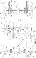
- a prime mover such as an internal combustion engine 22 drives an input shaft 24 of a gearbox/transmission unit 26 via a flywheel 28.
- the transmission 26 drives front and rear output (axle drive) shafts 32, 30 to provide propulsive drive to the respective axle assemblies 18, 20.
- the transmission 26 also provides drive to a rear power take-off drive shaft 64.
- the transmission input shaft 24 is connected at its inboard end to a planetary gear assembly indicated generally at 148.
- the purpose of the planetary gear assembly 148 is to split the torque provided by the input shaft 24 between a mechanical branch indicated generally at 150 and a hydrostatic branch indicated generally at 152.
- On the opposite side of the planetary gear assembly to the input shaft 24 is the rear power take off shaft 64.
- the hydrostatic branch 152 drives a hydraulic pump 140.
- the mechanical branch 150 is connected to the front axle drive shaft 32 and rear axle drive shaft 30 as follows. Torque is transmitted from the mechanical branch 150 of the planetary gear assembly 148 to the rear axle drive shaft 30 via a rear axle gear 154. Mounted on the same shaft as the rear axle drive gear 154 is an intermediary gear 156 which in turn drives a front axle drive gear 158 which selectively drives the front axle drive shaft 32.
- a first clutch 160 is provided to selectively engage and disengage the front axle drive shaft 32 from the rear axle drive shaft 30 or to control the ratio of torque distribution between the two axles. This allows grip to be optimised dependant on the ground conditions.
- the hydraulic pump 140 is hydraulically connected (not shown in Figure 2 for clarity) to a first hydraulic motor 142 which is driveably connected to the rear axle drive shaft 30 in order to provide hydraulic drive to the rear wheels.
- the hydraulic pump 140 is also connected in parallel to a second hydraulic motor 144 in order to provide hydraulic drive to the front axle drive shaft 32 as follows.
- the motor 144 is driveably connected to the front axle drive shaft 32 via first and second hydraulic motor gears 162, 164.
- a second clutch 166 allows the second hydraulic motor 144 to be selectively engaged and disengaged from the front axle drive shaft 32.
- Second hydraulic motor 144 is connected to front axle drive shaft 32 by gears 162, 164 having a high transmission ratio. This allows motor 144 to provide high torque at a limited, lower range of vehicle speeds. Consequently, at higher vehicle speeds, the motor 144 may be disconnected from the driveline via second clutch 166. Due to the layout, the first hydraulic motor 142 is provided for delivering lower torque but over the full range of vehicle speeds. However, in combination, both motors 142, 144 enable the transmission to provide a full transmission output power with variable torque, variable vehicle speed and variable driving direction over a full range of vehicle speeds.
- Rear axle drive output shaft 30 drives the vehicle rear axle left and right driveshafts 34L, 34R via rear axle differential 36.
- the rear axle assembly 20 further comprises left and right rear axle service brakes 38L, 38R (with respective park brakes 40L, 40R), left and right rear axle final drives 42L, 42R, and left and right rear wheels 44L, 44R.
- the service and park brakes may share a common set of brake disks 39L, 39R, with the service brake being spring-biased to the open position and the park brake spring-biased to the closed position.
- German utility model DE9204417U1 Such an arrangement is described in e.g. German utility model DE9204417U1 .
- front axle drive output shaft 32 drives the vehicle front axle left and right driveshafts 46L, 46R via cardan shaft 48 and front axle differential 50.
- the front axle assembly 18 further comprises left and right front axle service brakes 52L, 52R, left and right front axle final drives 54L, 54R, and left and right front wheels 56L, 56R.
- the controlled clutch arrangement comprising the first and second clutches 160, 166 under the direction of the vehicle control system 62 (described further below), the drive to the vehicle front wheels 56L, 56R may be selectively engaged or disengaged, or engaged with a controllably variable degree of clutch slippage to enable the engine output torque delivered to the axle assemblies 18, 20 to be controllably varied.
- the first clutch 160 is also provided to control the wheel velocity or rotational speeds of the axle assemblies 18, 20 to avoid malfunction of the transmission 26.
- the wheel velocity w is the velocity of a wheel in the contact point with the ground G and along the ground (radially).
- the rotational speed n of the wheel can be calculated and based on that the wheel velocity w can be determined by measuring the rotational speed n at any shaft in the driveline which is connected via a fixed, constant ratio to one of the wheel axles 18, 20.
- the wheel velocity wF (for front axle) and wR (for rear axle) should be equal under ideal conditions while due to the diverging tyre diameter, rotational speed nF of front axle and nR of rear axle are different.
- both rotational speeds nF, nR and also wF, wR can be monitored by measuring the rotational speed n at any shaft in the driveline which is connected to the respective wheel axles 18, 20.
- Control system 62 is permanently monitoring the signals coming from speed sensors S1 and S2.
- Sensor S1 is connected to the rear axle drive shaft 30 with a fixed ratio so that sensor S1 provides a signal indicative of the rotational speed of rear axle drive shaft 30 (referred to as n1) , rear axle left and right driveshafts 34L, 34R and thereby left and right rear wheels 44L, 44R.
- Sensor S2 is connected to the front axle drive shaft 32 with a fixed ratio so that sensor S2 provides a signal indicative of the rotational speed of front axle drive shaft 32 (referred to as n2), front axle left and right drive shafts 46L, 46R and thereby left and right front wheels 56L, 56R.
- different pivot angles can be provided for each motor allowing one motor can be pivoted to zero displacement (represented by a pivot angle of 0 degrees or 45 degrees, depending on specification) while the torque or speed output of the other motor is further adjusted.
- the first motor can be disconnected by clutch 166.
- the control system 62 and particularly the relationship between the displacement of first and second motor 142, 144, can be adapted. This allows the transmission system to be readily configured for different applications.
- the adjustment means is controlled depending on the vehicle speed v and that the adjustment means is designed so that for each vehicle speed v, a displacement (pivot angle) for pump 140, first and second motor 142, 144 is predetermined.
- a displacement pivot angle
- a predetermined displacement for pump 140, first and second motor 142, 144 is assigned which cannot be adapted in relation to each other.
- the wheel velocity for front and rear axle wF and wR should be the same if wheel-slip is equal for both axles (in simple terms, the ground G under the wheels shows the same condition).
- a wheel-slip of 10% would mean that the wheel velocity for front and rear axle wF and wR is 10% higher than the vehicle speed.
- the rotational speed nF and nR is equal, so the rotational speed n1 determined by sensor S1 and the rotational speed n2 determined by sensor S2 are also equal. If a tractor with different tyre sizes (in terms of the outer diameter) is regarded, rotational speed nF and nR would be different due to overall gear ratio between front axle and rear axle. So a comparison of the rotational speeds n1 and n2 to arrive at the deviation/difference in wheel velocity or rotational speed of front and rear axle wF and wR would require inclusion of the overall gear ratio. As this is standard engineering knowledge, the following description considers equal tyre sizes for both axles 18, 20 so that the overall gear ratio need not be applied and considered.
- first hydraulic motor 142 would stand still.
- second hydraulic motor 144 due to missing resistance /torque support at second motor 144, the oil would flow at a minimal pressure level (nearly pressureless) in second motor 144 assigned to front axle 18.
- both motors 142, 144 are connected in the same hydraulic circuit (in parallel), the same minimal pressure level would impinge first motor 142 assigned to rear axle 20.
- first motor 142 cannot supply torque. With front axle 18 spinning on sandy or iced ground and rear axle 20 standing still, the tractor would just slow down and stop.
- Changing the vehicle speed to adjust speeds and torque supplied by motors 142, 144, may help to a certain degree but not on ground which is glassy frozen. Furthermore reducing speed is not advantageous during agricultural work (e.g. ploughing or seeding) as the work result may suffer.
- Opening clutch 166 without second motor 144 adjusted to zero displacement would have the same result. This condition is only intended for higher speeds at which the adjustment means changes second motor 144 to zero displacement and the clutch 166 is disengaged while first motor 142 is adjusted to displacement above zero.
- control unit 62 is permanently adjusting the engagement of the clutch 160 as explained below:
- the monitoring process includes that the determined rotational speeds of sensors S1 and S2, are permanently compared to detect the wheel velocity difference/rotational speed difference. If during straight ahead driving the value of the wheel velocity difference/rotational speed difference exceeds a first wheel velocity difference threshold value say 5% (meaning that wheel velocity wF is 5% higher than wheel velocity wR) the control unit controllably engages clutch 166 until the first wheel velocity difference threshold value is undercut again. If the front axle spins on a sandy surface, this would result in that the clutch is further engaged so that the second motor 144 is drivingly connected to the rear axle which can support the torque to avoid spinning. This would also keep first motor under supply to drive the rear axle. The vehicle would not be forced into stand still then. This method keeps independent drive of both axles 18, 20 upheld most of the time to avoid torsional stresses in the driveline.
- a first wheel velocity difference threshold value say 5% (meaning that wheel velocity wF is 5% higher than wheel velocity wR)
- the control unit controllably engages clutch 166 until the
- a second wheel velocity difference threshold value is considered. Based on the fact that during a turn, due to Ackermann steering constraints, the steered front wheels roll on a greater curve radius (path) so that they have to speed up to pass the curved path at the same time compared to the rear wheels. So during turning, the clutch control unit 62 would consider a second wheel velocity difference threshold value which may be 15 to 20%. This higher level for the velocity difference threshold enables the vehicle to pass the curve but the spinning prevention is still active, so that in the case when the front wheels drive via icy surface in the curve, the system can still react. Furthermore, the drag capability (that the front wheels support the turn)
- a third wheel velocity difference threshold value_ is considered.
- the inner steered wheel is braked while the steered outer wheel should support the steering brake by speeding up to further drag the vehicle into the curve.
- the clutch control unit 62 would consider a third wheel velocity difference threshold value which may be 30%. This enables that the vehicle can pass the curve and steering brake but the spinning prevention is still active, so that in the case when the front wheels drive via icy surface in the curve, the system can still react
- second wheel velocity difference threshold and_third wheel velocity difference threshold value thereby depend on the geometry of the vehicle (wheel distance or wheelbase, maximum steering angle ⁇ , track width) as these parameters influence the path driven during a turn which themselves influence the wheel speed differences which must be allowed:
- the track width can be adapted with special axle arrangements (known as stub axles in the USA) so that also the steering angle may be limited.
- the steering angle may be limited by attaching a front loader.
- the values for the velocity difference thresholds which are suitably held in a data storage device 62a of the control system 62, may be adapted by the driver via the input device 13, or by the control system 62 recognizing these configurations.
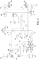
- FIG 3 shows a schematic circuit diagram of a pneumatically operable brake system for the tractor 10 of Figure 1 .
- a first brake circuit C1 is provided for activating left and right rear service brakes 38L, 38R individually for application to left and right rear wheels 44L, 44R respectively.
- This first brake circuit C1 comprises a first pressure control valve 70 and supply lines L3, L3a, L3b, L4, L4a and L4b.
- Left and right rear service brakes 38L, 38R are operated by respective left and right associated brake relay valves 72L, 72R.
- Lines L3a and L3b are linked by a shuttle valve 74 which passes the greater pressure in either of the lines to proportional valve 76 in the control circuit for rear park brakes 40L, 40R (described below).
- a second brake circuit C2 is provided for activating left and right front service brakes 52L, 52R individually for application to left and right front wheels 56L, 56R respectively.
- This second brake circuit C2 comprises a second pressure control valve 78 and supply lines L1, L1a, L1b, L2, L2a and L2b.
- Left and right front service brakes 52L, 52R are operated by respective left and right associated brake relay valves 80L, 80R.
- the service brakes 38L, 38R, 52L, 52R are activated by the driver by two levers, such as two foot pedals 82L, 82R.
- Left or first foot pedal 82L when pressed opens a left rear brake valve 84L and a left front brake valve 86L.
- Right or second foot pedal 82R when pressed opens a right rear brake valve 84R and a right front brake valve 86R.
- Pedals 82L, 82R will activate a piston or pistons 88 of a cylinder or cylinders (not shown) which activate the first and second pressure control valves 70, 78. Movement of either or both of the pedals 82L, 82R will activate both of the first and second pressure control valves 70, 78.
- the service brakes 38L, 38R, 52L, 52R are connected to a fluid supply 90 such as a compressor, or air chamber via their respective brake relay valves 72L, 72R, 80L, 80R.
- a fluid supply 90 such as a compressor, or air chamber
- the brake relay valves 72L, 72R, 80L, 80R are in a closed position which means that the brakes 38L, 38R, 52L, 52R are not activated.
- Each brake circuit C1, C2 is connected to a separate fluid reservoir of the fluid supply 90.
- the first brake circuit C1 including first control valve 70 is connected to fluid supply 90a
- the second brake circuit C2 including second control valve 78 is connected to fluid supply 90b.
- the first control valve 70 switches left associated rear brake valve 72L, or right associated rear brake valve 72R, or both of them, to an open position via left and/or right brake valves 84L, 84R.
- left and/or right brake valves 84L, 84R When the associated rear brake valve 84L, 84R is open, the respective rear service brake 38L, 38R is activated.
- Associated rear brake valves 84L, 84R are connected in parallel.
- the second control valve 78 switches left associated front brake valve 80L, or right associated front brake valve 80R, or both of them, to an open position via left and/or right brake valves 86L, 86R.
- left and/or right brake valves 86L, 86R When the associated front brake valve 86L, 86R is open, the respective front service brake 52L, 52R is activated.
- Associated front brake valves 86L, 86R are connected in parallel.
- the two foot pedals 82L, 82R must be connected by a locking means (not shown) so that only simultaneous movement is possible.
- This locking means can be provided as a pin which engages through the two foot pedals 82L, 82R and which is operated by the driver. Alternatively, the locking means may be engaged automatically, e.g. above a certain vehicle speed. Such locking means are described in applicant's published patent application WO2010/066864 .
- piston 88 activates first and second control valves 70, 78 and at the same time the front and rear brake valves 86L, 86R, 84L, 84R are opened. Air flows from the fluid supply 90b, along line L1, through second control valve 78, along line L2 through the front brake valves 86L, 86R and through to the respective front brake valves 80L, 80R which switches valves 80L, 80R to an open position. Air can then flow from the fluid supply 90b along line L1 and parallel lines L1a and L1b to the respective front service brakes 52L, 52R.
- air also flows from the fluid supply 90a, along line L4 through first control valve 70, along line L3 through left and right brake valves 84L, 84R and along lines L3a, L3b through to associated brake relay valves 72L, 72R which switch valves 72L, 72R to an open position. Air can then flow from air supply 90a through line L4, through lines L4a and L4b to activate rear service brakes 38L, 38R.
- the driver wishes to apply the brakes on one side only, for example the left front service brake 52L and left rear service brake 38L to help him steer left around a bend, the driver pushes the left foot pedal 82L only, after disengaging the above-mentioned locking means connecting the two foot pedals 82L, 82R during road operation.
- the rear park brakes 40L, 40R are controlled by a park brake control circuit C3 connected to a further separate reservoir 90c of fluid supply 90.
- a park brake control valve 92 activated by a hand brake lever, is operable to connect the fluid supply, via a relay valve 94 and respective left and right rear solenoid valves 96L, 96R, to release the park brakes 40L, 40R (and dosing park brake force).
- the solenoid valves 96L, 96R are spring biased to the operating position shown in which the output of relay valve 94 is connected to the park brakes 40L, 40R.
- the park brakes 40L, 40R are used to supplement the braking pressure applied by the rear service brakes 38L, 38R.
- the fluid supply 90 from reservoir 90c is connected as a further input to proportional valve 76 (along with the output from shuttle valve 74 in circuit C1) with the proportional valve out put on line L5 being connected to the left and right rear solenoid valves 96L, 96R.
- Operating one of the rear solenoid valves e.g. left rear solenoid valve 96L) disconnects the respective park brake 40L from the output of relay valve 94 and instead connects it to the output of proportional valve 76 on line L5.
- the effect of the proportional valve 76 is to reduce the opening pressure applied to the park brake 40L as the closure pressure on the corresponding service brake 38L is increased (So fluid pressure applied on the park brake is substantially inversely proportional to that applied on the service brake) such that the braking force applied by the park brake is substantially proportional to that applied by the service brake.
- This proportional application of the park brake during brake steering reduces the ground damage that may otherwise occur if maximum park brake force were applied regardless of service braking force (as would be the case with the above-mentioned combined park and service brake arrangement of DE9204417U1 ).
- Figure 4 shows an alternative embodiment of the invention in which the pedal-operated front brake valves 86L, 86R are replaced by solenoid-operated valves 98L, 98R connected between the line L2 output of second control valve 78 and the respective front brake valves 80L, 80R operating left and right front service brakes 52L, 52R.
- Other components of the arrangement of Figure 4 are the same as in Figure 3 , are denoted by the same reference numerals, and will not be further described.
- the brake circuit shown in Figure 4 may be adapted to a full electronic braking system (brake by wire) wherein the left rear brake valve 84L and the right rear brake valve 84R are not directly connected to two foot pedals 82L, 82R. Instead, solenoid valves are used to activate the rear service brakes 38L, 38R. The movement of the two foot pedals 82L, 82R may then be measured by sensors and forwarded to control unit 62, which in turn controls the solenoid valves. Furthermore, such a brake system may be provided with only one foot pedal. A further activation means may be provided so that the driver can activate steering brake operation or the system may automatically activate steering brake depending on sensed parameters (vehicle speed, field/road operation, etc.).
- park brake control valve 92 may be also solenoid valves (connected with control system 62) which is operable to connect the fluid supply, via a relay valve 94 and respective left and right rear solenoid valves 96L, 96R, to release or activate the park brakes 40L, 40R.
- solenoid valves connected with control system 62
- the brake force of the park brake under normal operating condition cannot be controlled by the driver, only ON/OFF condition is possible.
- the service brakes 38 are applied on one or both of the wheels on the inside of the turn at step 112 and (as described above) optionally the parking brake 40 of the rear wheel on the inside of the turn may be applied at step 114.
- the controllably varied level of braking force applied by the parking brake is preferably substantially proportional to the level of applied service brake force (as depicted with graph G2) while the fluid pressure applied on the park brake (as depicted with graph G3) is substantially inversely proportional to that applied on the service brake (as depicted with graph G4).
- the graphs G1 and G2 may show equal values but are depicted with a small offset for clarity reasons.
- the pedal stroke shown on the horizontal axis starts with 20% which means that before, no brakes are actuated but e.g. the brake lights are anyway switched on, e.g. at a stroke of 10% before the vehicle is braked.
- the second and third wheel velocity difference values between the front and rear axles may be set to a fixed amount, e.g. 15% and 30%.
- an optional step may comprise actively adjusting the wheel velocity difference values based on external factors identified by the sensors 11, such as:
- control system 62 may not activate the front service brake, while when the vehicle is heavier at the front, the system may not activate the additional brake force supplied by park brake. This situative brake control enables an efficient operation avoid excessive brake force to reduce soil damages. An ABS sensor giving wheel velocity to determine tyre slip may then be used for control of brakes and clutch.
- a further determination may be made at 120 prior to the start of a turn at 100 as to whether the vehicle is in a "safe" geographical location, namely a field. This determination may be made automatically in control system 62 on the basis of input from the geographical positioning system 15 ( Fig. 1 ).
- a method of brake steering in a four-wheel drive utility vehicle having a driven front axle carrying at least two front wheels, a driven rear axle carrying at least two rear wheels, a powertrain delivering torque to the front axle via a first motor and to the rear axle via a second motor, a controlled clutch arrangement operable to couple the outputs of the first and second motors to vary the distribution of delivered torque between the front and rear axles, and independently operable service brakes on each of the front and rear wheels.
- the method comprises determining a difference in wheel velocity between front and rear wheels; comparing the difference to a threshold value and, when exceeded, automatically engaging the controlled clutch arrangement. A determination is made as to whether or not the vehicle is performing a brake steering manoeuvre and the threshold value is adjusted accordingly. Additional braking force may be applied from independently operable park brakes on the rear wheels in inverse relationship to the level of service brake force applied.
Landscapes
- Engineering & Computer Science (AREA)
- Transportation (AREA)
- Mechanical Engineering (AREA)
- Chemical & Material Sciences (AREA)
- Combustion & Propulsion (AREA)
- Arrangement And Driving Of Transmission Devices (AREA)
Claims (15)
- Procédé de direction par freinage sur un véhicule utilitaire à quatre roues motrices (10) comportant un essieu avant moteur (18) supportant au moins deux roues avant (56L, 56R), un essieu arrière moteur (20) supportant au moins deux roues arrière (44L, 44R), un groupe de propulsion délivrant un couple à l'essieu arrière par l'intermédiaire d'un premier moteur (142) et à l'essieu avant par l'intermédiaire d'un second moteur (144), un agencement d'embrayage commandé (160, 166) pouvant servir, lorsqu'il est activé, à coupler la sortie des premier et second moteurs afin de modifier la distribution du couple délivré entre et les essieux avant et arrière, et pouvant indépendamment servir de frein de service (38L, 38R, 52L, 52R) sur chacune des roues avant et arrière, le procédé comprenant :la détermination d'une différence de vitesse de roue entre les roues avant et arrière ;la comparaison de la différence par rapport à une valeur de seuil et, lorsqu'elle est excédée, l'activation automatique de l'agencement d'embrayage commandé (160, 166) ;le véhicule se déplaçant sur un trajet sensiblement rectiligne, l'application d'un premier niveau de la valeur de seuil ;lors de l'entrée du véhicule dans un virage en accélérant, l'application d'un deuxième niveau de la valeur de seuil supérieur au premier ;lors de l'entrée du véhicule dans un virage en freinant, l'application des freins de service des roues avant et arrière du côté intérieur au virage et l'application d'un troisième niveau de la valeur de seuil supérieur au deuxième.
- Procédé de direction par freinage selon la revendication 1, dans lequel, lorsque le véhicule (10) est, en outre, équipé de freins de stationnement (40L, 40R) pouvant être commandés indépendamment sur chacune des roues arrière, lors de l'entrée dans un virage en freinant l'application aussi, et à un niveau d'effort de freinage prédéterminé, du frein de stationnement sur la roue arrière du côté intérieur au virage.
- Procédé de direction par freinage selon la revendication 2, dans lequel le niveau de l'effort de freinage de frein de stationnement appliqué sur une roue arrière lors de l'entrée d'un virage en freinant est sensiblement proportionnel au niveau de l'effort de freinage de frein de service appliqué sur la même roue.
- Procédé de direction par freinage selon l'une quelconque des revendications 1 à 3, dans lequel le niveau d'effort de freinage de frein de service appliqué au cours d'un virage en freinant est déterminé par le niveau de pression exercé par l'utilisateur du véhicule sur une commande de frein (82) du véhicule.
- Procédé de direction par freinage selon l'une quelconque des revendications 1 à 4, dans lequel au moins l'un des deuxième et troisième niveaux de seuil est déterminé au moins partiellement sur la base de l'empattement de véhicule.
- Procédé de direction par freinage selon l'une quelconque des revendications 1 à 5, comportant l'adaptation d'au moins l'un des deuxième et troisième niveaux du seuil en réponse à des modifications sur la largeur de voie du véhicule.
- Procédé de direction par freinage selon l'une quelconque des revendications 1 à 6, comportant l'adaptation d'au moins l'un des deuxième et troisième niveaux du seuil en réponse à des modifications sur l'angle de braquage maximum du véhicule.
- Procédé de direction par freinage selon l'une quelconque des revendications 1 à 4, dans lequel le rapport d'effort de freinage de service entre les roues avant et arrière est modifié de manière commandée sur la base d'un ou plusieurs des facteurs suivants :le poids brut du véhicule ;la quantité de ballast avant et/ou arrière transportée par le véhicule ;des informations de poids appartement à un outillage tracté ou transporté ;le niveau de patinage de roue mesuré sur une ou plusieurs roues du véhicule ;la pression de pneu dans un ou plusieurs pneus sur les roues respectives du véhicule ;l'angle de braquage commandé par un utilisateur du véhicule ;la vitesse courante du véhicule ;les conditions ambiantes externes au véhicule.
- Transmission destinée à un véhicule utilitaire à quatre roues motrices (10) comprenant :un essieu avant moteur (18) supportant au moins deux roues avant (56L, 56R) ;un essieu arrière moteur (20) supportant au moins deux roues arrière (44L, 44R) ;un groupe de propulsion délivrant un couple à l'essieu arrière par l'intermédiaire d'un premier moteur (142) et à l'essieu avant par l'intermédiaire d'un second moteur (144) ;un agencement d'embrayage commandé (160, 166) pouvant servir, lorsqu'il est activé, à coupler la sortie des premier et second moteurs afin de modifier la distribution du couple délivré entre les essieux avant et arrière ;la transmission étant caractérisée par des freins de service (38L, 38R, 52L, 52R) pouvant être commandés indépendamment sur chacune des roues avant et arrière ;des premier et second capteurs (SI, S2) disposés respectivement afin de déterminer la vitesse des roues avant et arrière ;un capteur de braquage (S3) disposé de manière à mesurer un angle de braquage du véhicule ;un dispositif de mémorisation de données (62a) mémorisant des données définissant des premier, deuxième et troisième niveaux d'une valeur de seuil ; etun dispositif de commande (62) couplé aux groupe de propulsion, aux capteurs, au dispositif de mémorisation de données, à l'agencement d'embrayage et aux freins de service, et configuré de manière à :déterminer une différence sur la vitesse de roue entre les roues avant et arrière à partir des premier et second capteurs ;comparer la différence à la valeur de seuil et, lorsqu'elle dépassée, activer automatiquement l'agencement d'embrayage commandé ;déterminer, à partir du capteur de braquage, si le véhicule se déplace sensiblement en ligne droite, et appliquer le premier niveau de la valeur de seuil ;déterminer, à partir du capteur de braquage si le véhicule entre dans un virage en accélérant, et appliquer le deuxième niveau de la valeur de seuil, lequel deuxième niveau est supérieur au premier ; etdéterminer au moins partiellement à partir du capteur de braquage si le véhicule entre dans un virage en freinant, appliquer les freins de service sur les roues avant et arrière du côté intérieur au virage et appliquer le troisième niveau de la valeur de seuil, lequel troisième niveau est supérieur au deuxième.
- Transmission selon la revendication 9, comprenant, en outre, des freins de stationnement (40L, 40R) pouvant être commandés indépendamment sur les roues arrière, le dispositif de commande (62) étant configuré, lors de la détection du fait que le véhicule entre dans un virage en freinant, de manière à appliquer aussi, et à un niveau prédéterminé d'un effort de freinage, le frein de stationnement sur la roue arrière du côté intérieur au virage.
- Transmission selon la revendication 10, dans laquelle le dispositif de commande (62) est configuré de manière à déterminer et à appliquer un niveau d'effort de freinage du frein de stationnement sur une roue arrière, lors de l'entrée dans un virage en freinant, qui est sensiblement proportionnel au niveau de l'effort de freinage de frein de service appliqué sur la même roue.
- Transmission selon l'une quelconque des revendications 9 à 11, comportant un dispositif de commande de frein pouvant être utilisé par l'opérateur (82) et des moyens destinés à déterminer une pression appliquée sur celui-ci, dans laquelle le dispositif de commande (62) est configuré de manière à définir le niveau de l'effort de freinage de frein de service appliqué au cours d'un virage sur la base du niveau de pression exercé par un utilisateur du véhicule sur le dispositif de commande de freinage.
- Transmission selon l'une quelconque des revendications 9 à 12, dans laquelle le dispositif de commande (62) comporte une entrée (11, 13) destinée à des données et est configuré de manière à modifier au moins l'un des premier, deuxième et troisième niveaux du seuil sur la base d'une valeur d'entrée pour un ou plusieurs de l'empattement du véhicule, de la largeur de voie du véhicule et de l'angle de braquage maximum du véhicule.
- Véhicule utilitaire (10) comportant une transmission selon l'une quelconque des revendications 9 à 13.
- Véhicule utilitaire (10) selon la revendication 14, comprenant, en outre, un dispositif de positionnement géographique (15) couplé au dispositif de commande (62), le dispositif de commande étant configuré de manière à ne pas mettre en œuvre un procédé de direction par freinage selon l'une quelconque des revendications 1 à 8 lors de la détermination du fait que le véhicule est à l'extérieur d'une zone géographique prédéterminée.
Applications Claiming Priority (2)
| Application Number | Priority Date | Filing Date | Title |
|---|---|---|---|
| GBGB1720470.2A GB201720470D0 (en) | 2017-12-08 | 2017-12-08 | Utility vehicle braking |
| PCT/EP2018/079456 WO2019110197A1 (fr) | 2017-12-08 | 2018-10-26 | Freinage de véhicule utilitaire |
Publications (2)
| Publication Number | Publication Date |
|---|---|
| EP3720760A1 EP3720760A1 (fr) | 2020-10-14 |
| EP3720760B1 true EP3720760B1 (fr) | 2021-12-01 |
Family
ID=61007013
Family Applications (1)
| Application Number | Title | Priority Date | Filing Date |
|---|---|---|---|
| EP18796404.4A Active EP3720760B1 (fr) | 2017-12-08 | 2018-10-26 | Freinage de véhicule utilitaire |
Country Status (4)
| Country | Link |
|---|---|
| US (1) | US11084529B2 (fr) |
| EP (1) | EP3720760B1 (fr) |
| GB (1) | GB201720470D0 (fr) |
| WO (1) | WO2019110197A1 (fr) |
Cited By (1)
| Publication number | Priority date | Publication date | Assignee | Title |
|---|---|---|---|---|
| WO2024038333A1 (fr) | 2022-08-15 | 2024-02-22 | Agco International Gmbh | Véhicule à embrayage pouvant être commandé entre un essieu avant et un essieu arrière et procédé de commande de rapport de mise en prise d'embrayage variable de l'embrayage |
Families Citing this family (4)
| Publication number | Priority date | Publication date | Assignee | Title |
|---|---|---|---|---|
| JP7326149B2 (ja) * | 2019-12-18 | 2023-08-15 | 株式会社クボタ | 作業機 |
| CN112937531B (zh) * | 2021-03-30 | 2023-01-03 | 柳工柳州传动件有限公司 | 一种工程机械的行车制动系统及制动方法 |
| IT202200007202A1 (it) * | 2022-04-12 | 2023-10-12 | Carraro Antonio Spa | Dispositivo di frenata sterzante per veicoli da lavoro |
| EP4516565A1 (fr) * | 2022-04-28 | 2025-03-05 | Kubota Corporation | Véhicule de chantier électrique |
Family Cites Families (9)
| Publication number | Priority date | Publication date | Assignee | Title |
|---|---|---|---|---|
| DE9204417U1 (de) * | 1992-04-01 | 1992-06-17 | Xaver Fendt & Co, 8952 Marktoberdorf | Druckmittelbetätigte Lenkbremsanlage für Kraftfahrzeuge mit Anhänger |
| JP4258265B2 (ja) * | 2003-04-30 | 2009-04-30 | 日産自動車株式会社 | 車両挙動制御装置 |
| GB2466066A (en) * | 2008-12-12 | 2010-06-16 | Agco Gmbh | Braking system having left and right brake pedals that are lockable together, and warning means to indicate the pedals are unlocked |
| ITTO20090699A1 (it) * | 2009-09-11 | 2011-03-12 | Cnh Italia Spa | Veicolo |
| US9022487B2 (en) * | 2011-08-11 | 2015-05-05 | Cnh Industrial America Llc | System and method for brake assisted turning |
| US8874346B2 (en) * | 2012-11-15 | 2014-10-28 | Caterpillar Inc. | System with blended anti-lock and stability control |
| GB201223546D0 (en) * | 2012-12-21 | 2013-02-13 | Agco Int Gmbh | Control mechanism for a continuously variable transmission |
| GB201322919D0 (en) * | 2013-12-23 | 2014-02-12 | Agco Int Gmbh | Brake arrangement |
| GB201518189D0 (en) * | 2015-10-14 | 2015-11-25 | Agco Int Gmbh | Agricultural vehicle driveline |
-
2017
- 2017-12-08 GB GBGB1720470.2A patent/GB201720470D0/en not_active Ceased
-
2018
- 2018-10-26 WO PCT/EP2018/079456 patent/WO2019110197A1/fr not_active Ceased
- 2018-10-26 US US16/770,455 patent/US11084529B2/en active Active
- 2018-10-26 EP EP18796404.4A patent/EP3720760B1/fr active Active
Cited By (1)
| Publication number | Priority date | Publication date | Assignee | Title |
|---|---|---|---|---|
| WO2024038333A1 (fr) | 2022-08-15 | 2024-02-22 | Agco International Gmbh | Véhicule à embrayage pouvant être commandé entre un essieu avant et un essieu arrière et procédé de commande de rapport de mise en prise d'embrayage variable de l'embrayage |
Also Published As
| Publication number | Publication date |
|---|---|
| GB201720470D0 (en) | 2018-01-24 |
| US11084529B2 (en) | 2021-08-10 |
| EP3720760A1 (fr) | 2020-10-14 |
| US20210053618A1 (en) | 2021-02-25 |
| WO2019110197A1 (fr) | 2019-06-13 |
Similar Documents
| Publication | Publication Date | Title |
|---|---|---|
| EP3720760B1 (fr) | Freinage de véhicule utilitaire | |
| EP1990230B1 (fr) | Système de commande pour véhicules avec au moins deux axes de véhicule conduisibles | |
| US8452504B2 (en) | Control system and method for automatic control of selection of on-demand all-wheel drive assembly for a vehicle drivetrain | |
| US8977467B2 (en) | Vehicle having a brake device which transfers a braking torque from rear wheels to the front wheels, with brake slip control | |
| US20080280719A1 (en) | Drive Arrangement For Vehicles With At Least Two Drivable Vehicle Axles | |
| US10166865B2 (en) | Automatic control of driveline states | |
| US9272703B2 (en) | Vehicle drive train control method and system | |
| EP2244920B1 (fr) | Procédé et système de freinage d'un véhicule | |
| EP3720745B1 (fr) | Freinage de véhicule utilitaire | |
| US11780498B2 (en) | Utility vehicle braking | |
| US10661800B2 (en) | Agricultural vehicle driveline | |
| US20060041346A1 (en) | Fault detecting apparatus for four-wheel drive vehicle | |
| EP1508466A1 (fr) | Système d'entraínement à toutes roues motrices | |
| US20160176406A1 (en) | Electro-hydraulic traction support | |
| KR101822952B1 (ko) | 견인 시스템이 제공되는 화물 적재 트럭 및 화물 적재 트럭의 견인 시스템을 제어하는 방법 | |
| US11192536B1 (en) | Brake torque distribution system using all-wheel-drive mode of powertrain, vehicle including same, and method | |
| EP1674320B1 (fr) | Dispositif de transmission pour véhicule à quatre roues motrices | |
| WO2024038333A1 (fr) | Véhicule à embrayage pouvant être commandé entre un essieu avant et un essieu arrière et procédé de commande de rapport de mise en prise d'embrayage variable de l'embrayage | |
| JPH01306329A (ja) | 四輪駆動型作業車 |
Legal Events
| Date | Code | Title | Description |
|---|---|---|---|
| STAA | Information on the status of an ep patent application or granted ep patent |
Free format text: STATUS: UNKNOWN |
|
| STAA | Information on the status of an ep patent application or granted ep patent |
Free format text: STATUS: THE INTERNATIONAL PUBLICATION HAS BEEN MADE |
|
| PUAI | Public reference made under article 153(3) epc to a published international application that has entered the european phase |
Free format text: ORIGINAL CODE: 0009012 |
|
| STAA | Information on the status of an ep patent application or granted ep patent |
Free format text: STATUS: REQUEST FOR EXAMINATION WAS MADE |
|
| 17P | Request for examination filed |
Effective date: 20200708 |
|
| AK | Designated contracting states |
Kind code of ref document: A1 Designated state(s): AL AT BE BG CH CY CZ DE DK EE ES FI FR GB GR HR HU IE IS IT LI LT LU LV MC MK MT NL NO PL PT RO RS SE SI SK SM TR |
|
| AX | Request for extension of the european patent |
Extension state: BA ME |
|
| DAV | Request for validation of the european patent (deleted) | ||
| DAX | Request for extension of the european patent (deleted) | ||
| GRAP | Despatch of communication of intention to grant a patent |
Free format text: ORIGINAL CODE: EPIDOSNIGR1 |
|
| STAA | Information on the status of an ep patent application or granted ep patent |
Free format text: STATUS: GRANT OF PATENT IS INTENDED |
|
| INTG | Intention to grant announced |
Effective date: 20210702 |
|
| GRAS | Grant fee paid |
Free format text: ORIGINAL CODE: EPIDOSNIGR3 |
|
| GRAA | (expected) grant |
Free format text: ORIGINAL CODE: 0009210 |
|
| STAA | Information on the status of an ep patent application or granted ep patent |
Free format text: STATUS: THE PATENT HAS BEEN GRANTED |
|
| AK | Designated contracting states |
Kind code of ref document: B1 Designated state(s): AL AT BE BG CH CY CZ DE DK EE ES FI FR GB GR HR HU IE IS IT LI LT LU LV MC MK MT NL NO PL PT RO RS SE SI SK SM TR |
|
| REG | Reference to a national code |
Ref country code: GB Ref legal event code: FG4D |
|
| REG | Reference to a national code |
Ref country code: AT Ref legal event code: REF Ref document number: 1451502 Country of ref document: AT Kind code of ref document: T Effective date: 20211215 Ref country code: CH Ref legal event code: EP |
|
| REG | Reference to a national code |
Ref country code: IE Ref legal event code: FG4D |
|
| REG | Reference to a national code |
Ref country code: DE Ref legal event code: R096 Ref document number: 602018027613 Country of ref document: DE |
|
| REG | Reference to a national code |
Ref country code: LT Ref legal event code: MG9D |
|
| REG | Reference to a national code |
Ref country code: NL Ref legal event code: MP Effective date: 20211201 |
|
| REG | Reference to a national code |
Ref country code: AT Ref legal event code: MK05 Ref document number: 1451502 Country of ref document: AT Kind code of ref document: T Effective date: 20211201 |
|
| PG25 | Lapsed in a contracting state [announced via postgrant information from national office to epo] |
Ref country code: RS Free format text: LAPSE BECAUSE OF FAILURE TO SUBMIT A TRANSLATION OF THE DESCRIPTION OR TO PAY THE FEE WITHIN THE PRESCRIBED TIME-LIMIT Effective date: 20211201 Ref country code: LT Free format text: LAPSE BECAUSE OF FAILURE TO SUBMIT A TRANSLATION OF THE DESCRIPTION OR TO PAY THE FEE WITHIN THE PRESCRIBED TIME-LIMIT Effective date: 20211201 Ref country code: FI Free format text: LAPSE BECAUSE OF FAILURE TO SUBMIT A TRANSLATION OF THE DESCRIPTION OR TO PAY THE FEE WITHIN THE PRESCRIBED TIME-LIMIT Effective date: 20211201 Ref country code: BG Free format text: LAPSE BECAUSE OF FAILURE TO SUBMIT A TRANSLATION OF THE DESCRIPTION OR TO PAY THE FEE WITHIN THE PRESCRIBED TIME-LIMIT Effective date: 20220301 Ref country code: AT Free format text: LAPSE BECAUSE OF FAILURE TO SUBMIT A TRANSLATION OF THE DESCRIPTION OR TO PAY THE FEE WITHIN THE PRESCRIBED TIME-LIMIT Effective date: 20211201 |
|
| PG25 | Lapsed in a contracting state [announced via postgrant information from national office to epo] |
Ref country code: SE Free format text: LAPSE BECAUSE OF FAILURE TO SUBMIT A TRANSLATION OF THE DESCRIPTION OR TO PAY THE FEE WITHIN THE PRESCRIBED TIME-LIMIT Effective date: 20211201 Ref country code: PL Free format text: LAPSE BECAUSE OF FAILURE TO SUBMIT A TRANSLATION OF THE DESCRIPTION OR TO PAY THE FEE WITHIN THE PRESCRIBED TIME-LIMIT Effective date: 20211201 Ref country code: NO Free format text: LAPSE BECAUSE OF FAILURE TO SUBMIT A TRANSLATION OF THE DESCRIPTION OR TO PAY THE FEE WITHIN THE PRESCRIBED TIME-LIMIT Effective date: 20220301 Ref country code: LV Free format text: LAPSE BECAUSE OF FAILURE TO SUBMIT A TRANSLATION OF THE DESCRIPTION OR TO PAY THE FEE WITHIN THE PRESCRIBED TIME-LIMIT Effective date: 20211201 Ref country code: HR Free format text: LAPSE BECAUSE OF FAILURE TO SUBMIT A TRANSLATION OF THE DESCRIPTION OR TO PAY THE FEE WITHIN THE PRESCRIBED TIME-LIMIT Effective date: 20211201 Ref country code: GR Free format text: LAPSE BECAUSE OF FAILURE TO SUBMIT A TRANSLATION OF THE DESCRIPTION OR TO PAY THE FEE WITHIN THE PRESCRIBED TIME-LIMIT Effective date: 20220302 |
|
| PG25 | Lapsed in a contracting state [announced via postgrant information from national office to epo] |
Ref country code: NL Free format text: LAPSE BECAUSE OF FAILURE TO SUBMIT A TRANSLATION OF THE DESCRIPTION OR TO PAY THE FEE WITHIN THE PRESCRIBED TIME-LIMIT Effective date: 20211201 |
|
| PG25 | Lapsed in a contracting state [announced via postgrant information from national office to epo] |
Ref country code: SM Free format text: LAPSE BECAUSE OF FAILURE TO SUBMIT A TRANSLATION OF THE DESCRIPTION OR TO PAY THE FEE WITHIN THE PRESCRIBED TIME-LIMIT Effective date: 20211201 Ref country code: SK Free format text: LAPSE BECAUSE OF FAILURE TO SUBMIT A TRANSLATION OF THE DESCRIPTION OR TO PAY THE FEE WITHIN THE PRESCRIBED TIME-LIMIT Effective date: 20211201 Ref country code: RO Free format text: LAPSE BECAUSE OF FAILURE TO SUBMIT A TRANSLATION OF THE DESCRIPTION OR TO PAY THE FEE WITHIN THE PRESCRIBED TIME-LIMIT Effective date: 20211201 Ref country code: PT Free format text: LAPSE BECAUSE OF FAILURE TO SUBMIT A TRANSLATION OF THE DESCRIPTION OR TO PAY THE FEE WITHIN THE PRESCRIBED TIME-LIMIT Effective date: 20220401 Ref country code: ES Free format text: LAPSE BECAUSE OF FAILURE TO SUBMIT A TRANSLATION OF THE DESCRIPTION OR TO PAY THE FEE WITHIN THE PRESCRIBED TIME-LIMIT Effective date: 20211201 Ref country code: EE Free format text: LAPSE BECAUSE OF FAILURE TO SUBMIT A TRANSLATION OF THE DESCRIPTION OR TO PAY THE FEE WITHIN THE PRESCRIBED TIME-LIMIT Effective date: 20211201 Ref country code: CZ Free format text: LAPSE BECAUSE OF FAILURE TO SUBMIT A TRANSLATION OF THE DESCRIPTION OR TO PAY THE FEE WITHIN THE PRESCRIBED TIME-LIMIT Effective date: 20211201 |
|
| REG | Reference to a national code |
Ref country code: DE Ref legal event code: R097 Ref document number: 602018027613 Country of ref document: DE |
|
| PG25 | Lapsed in a contracting state [announced via postgrant information from national office to epo] |
Ref country code: IS Free format text: LAPSE BECAUSE OF FAILURE TO SUBMIT A TRANSLATION OF THE DESCRIPTION OR TO PAY THE FEE WITHIN THE PRESCRIBED TIME-LIMIT Effective date: 20220401 |
|
| PLBE | No opposition filed within time limit |
Free format text: ORIGINAL CODE: 0009261 |
|
| STAA | Information on the status of an ep patent application or granted ep patent |
Free format text: STATUS: NO OPPOSITION FILED WITHIN TIME LIMIT |
|
| PG25 | Lapsed in a contracting state [announced via postgrant information from national office to epo] |
Ref country code: DK Free format text: LAPSE BECAUSE OF FAILURE TO SUBMIT A TRANSLATION OF THE DESCRIPTION OR TO PAY THE FEE WITHIN THE PRESCRIBED TIME-LIMIT Effective date: 20211201 Ref country code: AL Free format text: LAPSE BECAUSE OF FAILURE TO SUBMIT A TRANSLATION OF THE DESCRIPTION OR TO PAY THE FEE WITHIN THE PRESCRIBED TIME-LIMIT Effective date: 20211201 |
|
| 26N | No opposition filed |
Effective date: 20220902 |
|
| PG25 | Lapsed in a contracting state [announced via postgrant information from national office to epo] |
Ref country code: SI Free format text: LAPSE BECAUSE OF FAILURE TO SUBMIT A TRANSLATION OF THE DESCRIPTION OR TO PAY THE FEE WITHIN THE PRESCRIBED TIME-LIMIT Effective date: 20211201 |
|
| PG25 | Lapsed in a contracting state [announced via postgrant information from national office to epo] |
Ref country code: MC Free format text: LAPSE BECAUSE OF FAILURE TO SUBMIT A TRANSLATION OF THE DESCRIPTION OR TO PAY THE FEE WITHIN THE PRESCRIBED TIME-LIMIT Effective date: 20211201 |
|
| REG | Reference to a national code |
Ref country code: CH Ref legal event code: PL |
|
| P01 | Opt-out of the competence of the unified patent court (upc) registered |
Effective date: 20230518 |
|
| REG | Reference to a national code |
Ref country code: BE Ref legal event code: MM Effective date: 20221031 |
|
| GBPC | Gb: european patent ceased through non-payment of renewal fee |
Effective date: 20221026 |
|
| PG25 | Lapsed in a contracting state [announced via postgrant information from national office to epo] |
Ref country code: LU Free format text: LAPSE BECAUSE OF NON-PAYMENT OF DUE FEES Effective date: 20221026 |
|
| PG25 | Lapsed in a contracting state [announced via postgrant information from national office to epo] |
Ref country code: LI Free format text: LAPSE BECAUSE OF NON-PAYMENT OF DUE FEES Effective date: 20221031 Ref country code: CH Free format text: LAPSE BECAUSE OF NON-PAYMENT OF DUE FEES Effective date: 20221031 |
|
| PG25 | Lapsed in a contracting state [announced via postgrant information from national office to epo] |
Ref country code: BE Free format text: LAPSE BECAUSE OF NON-PAYMENT OF DUE FEES Effective date: 20221031 |
|
| PG25 | Lapsed in a contracting state [announced via postgrant information from national office to epo] |
Ref country code: IE Free format text: LAPSE BECAUSE OF NON-PAYMENT OF DUE FEES Effective date: 20221026 Ref country code: GB Free format text: LAPSE BECAUSE OF NON-PAYMENT OF DUE FEES Effective date: 20221026 |
|
| PG25 | Lapsed in a contracting state [announced via postgrant information from national office to epo] |
Ref country code: CY Free format text: LAPSE BECAUSE OF FAILURE TO SUBMIT A TRANSLATION OF THE DESCRIPTION OR TO PAY THE FEE WITHIN THE PRESCRIBED TIME-LIMIT Effective date: 20211201 |
|
| PG25 | Lapsed in a contracting state [announced via postgrant information from national office to epo] |
Ref country code: MK Free format text: LAPSE BECAUSE OF FAILURE TO SUBMIT A TRANSLATION OF THE DESCRIPTION OR TO PAY THE FEE WITHIN THE PRESCRIBED TIME-LIMIT Effective date: 20211201 Ref country code: HU Free format text: LAPSE BECAUSE OF FAILURE TO SUBMIT A TRANSLATION OF THE DESCRIPTION OR TO PAY THE FEE WITHIN THE PRESCRIBED TIME-LIMIT; INVALID AB INITIO Effective date: 20181026 |
|
| PG25 | Lapsed in a contracting state [announced via postgrant information from national office to epo] |
Ref country code: TR Free format text: LAPSE BECAUSE OF FAILURE TO SUBMIT A TRANSLATION OF THE DESCRIPTION OR TO PAY THE FEE WITHIN THE PRESCRIBED TIME-LIMIT Effective date: 20211201 |
|
| PG25 | Lapsed in a contracting state [announced via postgrant information from national office to epo] |
Ref country code: MT Free format text: LAPSE BECAUSE OF FAILURE TO SUBMIT A TRANSLATION OF THE DESCRIPTION OR TO PAY THE FEE WITHIN THE PRESCRIBED TIME-LIMIT Effective date: 20211201 |
|
| PGFP | Annual fee paid to national office [announced via postgrant information from national office to epo] |
Ref country code: DE Payment date: 20251021 Year of fee payment: 8 |
|
| PGFP | Annual fee paid to national office [announced via postgrant information from national office to epo] |
Ref country code: IT Payment date: 20251021 Year of fee payment: 8 |
|
| PGFP | Annual fee paid to national office [announced via postgrant information from national office to epo] |
Ref country code: FR Payment date: 20251030 Year of fee payment: 8 |