EP3722067A1 - Spritzgussheisskanalverteiler - Google Patents
Spritzgussheisskanalverteiler Download PDFInfo
- Publication number
- EP3722067A1 EP3722067A1 EP20164114.9A EP20164114A EP3722067A1 EP 3722067 A1 EP3722067 A1 EP 3722067A1 EP 20164114 A EP20164114 A EP 20164114A EP 3722067 A1 EP3722067 A1 EP 3722067A1
- Authority
- EP
- European Patent Office
- Prior art keywords
- block
- passage
- manifold
- changing
- relay
- Prior art date
- Legal status (The legal status is an assumption and is not a legal conclusion. Google has not performed a legal analysis and makes no representation as to the accuracy of the status listed.)
- Withdrawn
Links
- 238000001746 injection moulding Methods 0.000 title claims description 20
- 238000002347 injection Methods 0.000 claims abstract description 26
- 239000007924 injection Substances 0.000 claims abstract description 26
- 239000000463 material Substances 0.000 claims abstract description 22
- 239000012768 molten material Substances 0.000 claims description 5
- 230000004048 modification Effects 0.000 description 5
- 238000012986 modification Methods 0.000 description 5
- 238000004519 manufacturing process Methods 0.000 description 4
- 229910000831 Steel Inorganic materials 0.000 description 3
- 239000010959 steel Substances 0.000 description 3
- 238000011144 upstream manufacturing Methods 0.000 description 3
- 238000000034 method Methods 0.000 description 2
- 238000010276 construction Methods 0.000 description 1
- 239000004033 plastic Substances 0.000 description 1
- 229910001220 stainless steel Inorganic materials 0.000 description 1
- 239000010935 stainless steel Substances 0.000 description 1
- 229920001169 thermoplastic Polymers 0.000 description 1
Images


Classifications
-
- B—PERFORMING OPERATIONS; TRANSPORTING
- B29—WORKING OF PLASTICS; WORKING OF SUBSTANCES IN A PLASTIC STATE IN GENERAL
- B29C—SHAPING OR JOINING OF PLASTICS; SHAPING OF MATERIAL IN A PLASTIC STATE, NOT OTHERWISE PROVIDED FOR; AFTER-TREATMENT OF THE SHAPED PRODUCTS, e.g. REPAIRING
- B29C45/00—Injection moulding, i.e. forcing the required volume of moulding material through a nozzle into a closed mould; Apparatus therefor
- B29C45/17—Component parts, details or accessories; Auxiliary operations
- B29C45/26—Moulds
- B29C45/27—Sprue channels ; Runner channels or runner nozzles
- B29C45/2725—Manifolds
- B29C45/2727—Modular manifolds; Connections between spaced manifold elements
-
- B—PERFORMING OPERATIONS; TRANSPORTING
- B29—WORKING OF PLASTICS; WORKING OF SUBSTANCES IN A PLASTIC STATE IN GENERAL
- B29C—SHAPING OR JOINING OF PLASTICS; SHAPING OF MATERIAL IN A PLASTIC STATE, NOT OTHERWISE PROVIDED FOR; AFTER-TREATMENT OF THE SHAPED PRODUCTS, e.g. REPAIRING
- B29C45/00—Injection moulding, i.e. forcing the required volume of moulding material through a nozzle into a closed mould; Apparatus therefor
- B29C45/17—Component parts, details or accessories; Auxiliary operations
- B29C45/26—Moulds
- B29C45/27—Sprue channels ; Runner channels or runner nozzles
- B29C45/2725—Manifolds
-
- B—PERFORMING OPERATIONS; TRANSPORTING
- B29—WORKING OF PLASTICS; WORKING OF SUBSTANCES IN A PLASTIC STATE IN GENERAL
- B29C—SHAPING OR JOINING OF PLASTICS; SHAPING OF MATERIAL IN A PLASTIC STATE, NOT OTHERWISE PROVIDED FOR; AFTER-TREATMENT OF THE SHAPED PRODUCTS, e.g. REPAIRING
- B29C45/00—Injection moulding, i.e. forcing the required volume of moulding material through a nozzle into a closed mould; Apparatus therefor
- B29C45/17—Component parts, details or accessories; Auxiliary operations
- B29C45/26—Moulds
- B29C45/27—Sprue channels ; Runner channels or runner nozzles
- B29C45/2725—Manifolds
- B29C2045/273—Manifolds stacked manifolds
-
- B—PERFORMING OPERATIONS; TRANSPORTING
- B29—WORKING OF PLASTICS; WORKING OF SUBSTANCES IN A PLASTIC STATE IN GENERAL
- B29C—SHAPING OR JOINING OF PLASTICS; SHAPING OF MATERIAL IN A PLASTIC STATE, NOT OTHERWISE PROVIDED FOR; AFTER-TREATMENT OF THE SHAPED PRODUCTS, e.g. REPAIRING
- B29C45/00—Injection moulding, i.e. forcing the required volume of moulding material through a nozzle into a closed mould; Apparatus therefor
- B29C45/17—Component parts, details or accessories; Auxiliary operations
- B29C45/26—Moulds
- B29C45/27—Sprue channels ; Runner channels or runner nozzles
- B29C45/2725—Manifolds
- B29C2045/2733—Inserts, plugs, bushings
Definitions
- the present disclosure relates to a manifold for an injection molding hot runner.
- an injection molding hot runner is disposed between an injection device, which delivers molten material, and a mold, which molds a product using the material.
- the injection molding hot runner includes a manifold that has a passage for delivering the material from the injection device to the mold.
- the position of the gate (the position at which material is injected) of a mold varies depending on the product manufactured with material, that is, depending on the mold that molds the product. If the gate position varies depending on the mold, the positional relationship between the material delivery position of the injection device and the gate position of the mold changes.
- a dedicated manifold for an injection molding hot runner is used for each mold. That is, a manifold that corresponds to the positional relationship between the gate position of the mold and the delivery position of the injection device is used.
- the above-described injection molding hot runner also uses a dedicated manifold for each mold, which molds a product.
- each manifold cannot be used in a mold for other products or in a mold that is used to mold the same product but has a different gate position. If a dedicated manifold is prepared for each mold, the manufacturing costs for the manifolds are increased, which inevitably extends the manufacturing time.
- a manifold for an injection molding hot runner is provided that is disposed between an injection device that delivers molten material and a mold that molds a product using the material.
- the manifold includes a passage through which the material flows from the injection device to the mold.
- the manifold for an injection molding hot runner includes an inlet block that is connected to the injection device, an outlet block that is separated from the inlet block and is connected to the mold, and a first relay block that is disposed between the inlet block and the outlet block in an extending direction of the passage.
- the passage is defined to pass through an interior of the inlet block, the first relay block, and the outlet block.
- the first relay block is configured to be replaceable by a second relay block, which has at least one of a function of changing the extending direction of the passage and a function of dividing the passage into branches.
- Exemplary embodiments may have different forms, and are not limited to the examples described. However, the examples described are thorough and complete, and convey the full scope of the disclosure to one of ordinary skill in the art.
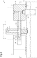
- a manifold 15 for an injection molding hot runner 11 will now be described with reference to the drawings.
- the injection molding hot runner 11 is disposed between an injection device 12, which delivers molten material (thermoplastic plastic in the present embodiment), and a mold 13, which molds a product with the material.
- the injection molding hot runner 11 includes the manifold 15 that has a passage 14 for delivering the material from the injection device 12 to the mold 13.
- the manifold 15 is made of steel and includes an inlet block 16, an outlet block 17, a first relay block 18, and a length-changing block 19.
- the inlet block 16 is connected to the injection device 12 from below.
- the outlet block 17 is separated from the inlet block 16 and is connected to the mold 13 from above.
- the first relay block 18 is disposed between the inlet block 16 and the outlet block 17 in the extending direction of the passage 14.
- the length-changing block 19 is disposed between the first relay block 18 and the outlet block 17.
- the inlet block 16 and the outlet block 17 are connected to each other via the first relay block 18 and the length-changing block 19.
- the passage 14 is formed to extend through the interior of the inlet block 16, the first relay block 18, the length-changing block 19, and the outlet block 17. That is, the manifold 15 has a structure in which the upstream end of the first relay block 18 is connected to the downstream end of the inlet block 16, the upstream end of the length-changing block 19 is connected to the downstream end of the first relay block 18, and the upstream end of the outlet block 17 is connected to the downstream end of the length-changing block 19.
- the upper part of the first relay block 18 is detachably connected to the lower end (lower side) of the inlet block 16, a side part of the length-changing block 19 is detachably connected to a side part of the first relay block 18, and a side part of the outlet block 17 is detachably connected to a side part of the length-changing block 19 that is opposite to the first relay block 18.
- thread portions are respectively formed at the portion of the inlet block 16 that is connected to the first relay block 18, the portion of the first relay block 18 that is connected to the inlet block 16, the portion of the first relay block 18 that is connected to the length-changing block 19, the portion of the length-changing block 19 that is connected to the first relay block 18, the portion of the length-changing block 19 that is connected to the outlet block 17, and the portion of the outlet block 17 that is connected to the length-changing block 19.
- the inlet block 16 and the first relay block 18 are detachably connected to each other by screwing the thread portions (not shown) to each other.
- the first relay block 18 and the length-changing block 19 are detachably connected to each other by screwing the thread portions (not shown) to each other.
- the length-changing block 19 and the outlet block 17 are detachably connected to each other by screwing the thread portions (not shown) to each other.
- the first relay block 18 and the length-changing block 19 can be easily displaced by other blocks. That is, in the present embodiment, the first relay block 18 can be replaced by a second relay block 30 (refer to Figs. 2 and 3 ), which will be discussed below.
- the second relay block 30 has a function of changing the extending direction of the passage 14 and dividing the passage 14 into branches.
- the length-changing block 19 can be replaced by a length-changing block that has a different passage length.
- the passage 14 extends vertically in the inlet block 16, vertically downward and then horizontally in the first relay block 18, horizontally in the length-changing block 19, horizontally and then vertically downward in the outlet block 17. It can be said that the first relay block 18 has a function of changing the extending direction of the passage 14 from a vertically downward direction to a horizontal direction.
- the manifold 15 (including the second relay block 30 shown in Figs. 2 and 3 ) is formed by a three-dimensional modeling machine (3D printer) to have a structure in which the passage 14 extends with a constant cross-sectional area.
- the inlet block 16, the outlet block 17, the first relay block 18, and the length-changing block 19, which constitute the manifold 15 are configured to be heated by a heater (not shown) to maintain the molten state of the material that passes through the passage 14.
- the first relay block 18 and the outlet block 17 in the manifold 15 are supported by the mold 13 with support legs 20 in between.
- the support legs 20 each include a heat insulating member 21 at the portion that contacts the mold 13.
- the heat insulating member 21 is made of a material (for example, stainless steel) having a thermal conductivity lower than that of the material of which the manifold 15 is made (steel in the present embodiment).
- the upper end of the inlet block 16 is connected to a material delivery position P1 of the injection device 12.
- the delivery position P1 of the injection device 12 and the passage 14 in the inlet block 16 are continuous with each other. Thus, the material delivered from the delivery position P1 of the injection device 12 flows into the passage 14 in the inlet block 16.
- a nozzle unit 22 is attached to the outlet block 17.
- the nozzle unit 22 is configured to inject the material in the passage 14 to a gate position P2 in the mold 13 (the position at which material is injected).
- the passage 14 in the outlet block 17 is connected to the gate position P2 of the mold 13 via the nozzle unit 22.
- the nozzle unit 22 is configured to selectively connect and disconnect the passage 14 in the manifold 15 to and from the gate position P2 of the mold 13. Through the connection and disconnection, the nozzle unit 22 injects or stops injecting the material in the passage 14 to the gate position P2 of the mold 13.
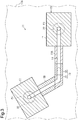
- the mold 13A has two gates respectively located at a gate position P3 and a gate position P4.
- the horizontal distance from the delivery position P1 of the injection device 12 to the gate position P3 is different from the horizontal distance from the delivery position P1 of the injection device 12 to the gate position P4.
- the second relay block 30 includes a direction-changing block 31, which changes the extending direction of the passage 14, and a branch block 32, which divides the passage 14 into two branches.
- the branch block 32 is screwed and connected to the lower part of the inlet block 16. Accordingly, the branch block 32 is arranged between the inlet block 16 and the support leg 20 in the vertical direction.
- the branch block 32 divides the passage 14, which extends vertically downward from the inlet block 16, into two branches that extend horizontally in directions 180° apart from each other. That is, the passage 14 in the branch block 32 has the shape of a T-junction.
- a length-changing block 19A is screwed and connected to one of the two horizontally divided branches of the passage 14 in the branch block 32.
- the direction-changing block 31 is screwed and connected to the other branch of the passage 14.
- the length-changing block 19A has a passage length different from that of the length-changing block 19 (refer to Fig. 1 ). That is, the direction-changing block 31 and the length-changing block 19A are each arranged to be adjacent to the branch block 32 in the horizontal direction. In other words, the branch block 32 is sandwiched by the direction-changing block 31 and the length-changing block 19A in the horizontal direction.
- the portion of the length-changing block 19A on the side opposite to the branch block 32 is screwed and connected to the outlet block 17, which is disposed on the gate position P3 of the mold 13A.
- the length of the length-changing block 19A is set in advance to be equal to the horizontal distance between the branch block 32 and the outlet block 17, which is disposed on the gate position P3.
- the portion of the passage 14 defined in the direction-changing block 31 is formed such that the passage 14, which extends horizontally from the branch block 32, is bent in a horizontal direction by an arbitrary angle (120° in the present embodiment).
- a length-changing block 19B is screwed to and connected to the downstream portion of the passage 14 in the direction-changing block 31.
- the length-changing block 19B has a passage length different from that of the length-changing block 19 (refer to Fig. 1 ).
- the portion of the length-changing block 19B on the side opposite to the direction-changing block 31 is screwed and connected to the outlet block 17, which is disposed on the gate position P4 of the mold 13A.
- the length of the length-changing block 19B is set in advance to be equal to the horizontal distance between the direction-changing block 31 and the outlet block 17, which is disposed on the gate position P4.
- the manifold 15 of the present embodiment allows the first relay block 18 to be replaced by the second relay block 30, the length-changing block 19 to be replaced by another length-changing block 19A, which has a different passage length, and the length-changing block 19B to be added.
- the manifold 15 can be used with the mold 13A, which manufactures a product different from that of the mold 13 and has a different number of gates at different positions.
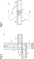
- the second relay block 30 of the manifold 15 may be replaced by a second relay block 30A.
- the second relay block 30A is a single component that includes a branch block 32A and a direction-changing block 31A located below the branch block 32A.
- the branch block 32A and the direction-changing block 31A are integrated to be rotational relative to each other.
- the branch block 32A of the second relay block 30A is rotationally connected to the lower end of the inlet block 16, and the lower end of the direction-changing block 31A of the second relay block 30A is supported by the support leg 20 so as not to hinder rotation of the direction-changing block 31A.
- branch block 32A and the direction-changing block 31A are rotational about the same central axis extending in the vertical direction.
- the branch block 32A divides the passage 14, which extends vertically from the inlet block 16, into a branch extending horizontally and a branch extending vertically downward.
- the direction-changing block 31A bends the passage 14, which extends vertically from the branch block 32A, at a right angle, so as to change the extending direction of the passage 14 to the horizontal direction.
- a horizontally extending length-changing block 19C is connected to the portion of the branch block 32A on the side of the horizontally extending portion of the passage 14.
- Another horizontally extending length-changing block 19D is connected to the downstream portion of the passage 14 in the direction-changing block 31A.
- This configuration allows the directions of the length-changing block 19C and the length-changing block 19D in the horizontal plane to be changed freely by rotating the branch block 32A and the direction-changing block 31A as shown in Figs. 4 and 5 . Therefore, in a case in which the outlet blocks 17, the number of which is two, for example, are disposed on the gates of a mold, wherever the outlet blocks 17 are located, the length-changing block 19C and the length-changing block 19D can be easily directed to the respective outlet blocks 17.
- the length-changing block 19C and the length-changing block 19D are set to have desirable lengths in advance.
- the passage 14 does not necessarily need to extend with a constant cross-sectional area.
- the second relay block 30 may be constituted by one of the direction-changing block 31 and the branch block 32.
- the direction-changing block 31 and the branch block 32 do not necessarily need to be adjacent to each other.
- the first relay block 18 does not necessarily need to be arranged below the inlet block 16.
- the inlet block 16 may be bent into an L-shape, and the first relay block 18 may be arranged next to the inlet block 16 in the horizontal direction.
- the first relay block 18 may be configured, for example, to divide the passage 14 into two branches.
- the length-changing block 19 may be omitted.
- the angle by which the passage 14 is bent or the degree by which the passage 14 is curved in the first relay block 18 may be changed.
- the angle by which the passage 14 is bent or the degree by which the passage 14 is curved in the direction-changing block 31 may be changed.
- the branch block 32 may be configured to divide the passage 14 into three or more branches.
- the angle formed by the branches of the passage 14 is not limited to 180°, but may be 120°, 90°, or 45°.
- the passage 14 in the branch block 32 may be tilted with respect to the horizontal direction as shown in Fig. 7 .
- the second relay block 30 may be a single component formed by integrating the direction-changing block 31 and the branch block 32. In this case, the number of branches of the passage 14 and the angle by which the passage 14 is bent or the degree by which the passage 14 is curved may be changed.
- connection of the inlet block 16, the outlet block 17, the first relay block 18, the length-changing block 19, and the second relay block 30 does not necessarily need to be achieved by thread portions (not shown), but may be achieved by bolts or clips.
- the manifold 15 does not necessarily need to be made of steel, but may be made of a heat-resistant plastic.
- the manifold 15 is located above the mold 13.
- the manifold 15 may be disposed inside the mold 13 to connect the injection device 12 and the gate position to each other.
- the manifold 15 for the injection molding hot runner 11 can be considered to be provided between the injection device 12 and the mold 13.
- a manifold includes a passage through which material flows from an injection device to a mold.
- the manifold includes an inlet block connected to the injection device, an outlet block, which is separated from the inlet block and connected to the mold, and a first relay block disposed between the inlet block and the outlet block in the extending direction of the passage.
- the passage is defined to pass through the interior of the inlet block, the first relay block, and the outlet block.
- the first relay block is configured to be replaceable by a second relay block, which has at least one of a function of changing the extending direction of the passage and a function of dividing the passage into branches.
Landscapes
- Engineering & Computer Science (AREA)
- Manufacturing & Machinery (AREA)
- Mechanical Engineering (AREA)
- Moulds For Moulding Plastics Or The Like (AREA)
Applications Claiming Priority (1)
| Application Number | Priority Date | Filing Date | Title |
|---|---|---|---|
| JP2019074833A JP7183929B2 (ja) | 2019-04-10 | 2019-04-10 | 射出成形用ホットランナのマニホールド |
Publications (1)
| Publication Number | Publication Date |
|---|---|
| EP3722067A1 true EP3722067A1 (de) | 2020-10-14 |
Family
ID=69846276
Family Applications (1)
| Application Number | Title | Priority Date | Filing Date |
|---|---|---|---|
| EP20164114.9A Withdrawn EP3722067A1 (de) | 2019-04-10 | 2020-03-19 | Spritzgussheisskanalverteiler |
Country Status (3)
| Country | Link |
|---|---|
| EP (1) | EP3722067A1 (de) |
| JP (1) | JP7183929B2 (de) |
| CN (1) | CN111805851A (de) |
Citations (6)
| Publication number | Priority date | Publication date | Assignee | Title |
|---|---|---|---|---|
| FR2564372A1 (fr) * | 1984-05-16 | 1985-11-22 | Contherm Srl | Structure de bloc d'injection pour l'alimentation de moules en matiere thermoplastique fondue |
| JPS6321812B2 (de) | 1981-03-23 | 1988-05-09 | Mitsubishi Motors Corp | |
| DE4425981A1 (de) * | 1994-07-22 | 1996-01-25 | Brandt Geb Brandt Ursula | Vorrichtung zur Herstellung von Formteilen insbesondere aus Gummi-Elastomer-Material |
| WO2005058577A1 (de) * | 2003-12-17 | 2005-06-30 | S.P.G. Promatrix B.V. | Heisskanalsystem |
| DE102011056060A1 (de) * | 2011-12-05 | 2013-06-06 | EWIKON Heißkanalsysteme GmbH | Heißkanal-Verteileranordnung für ein Heißkanalsystem |
| WO2014086516A1 (de) * | 2012-12-03 | 2014-06-12 | Fostag Formenbau Ag | Spritzgusswerkzeug mit heisskanalverteiler |
Family Cites Families (3)
| Publication number | Priority date | Publication date | Assignee | Title |
|---|---|---|---|---|
| JPH0624181Y2 (ja) * | 1990-07-09 | 1994-06-29 | 池上金型工業株式会社 | 射出成形用金型 |
| JP2004255754A (ja) | 2003-02-26 | 2004-09-16 | Ricoh Co Ltd | マニホ−ルド |
| JP2013169697A (ja) | 2012-02-21 | 2013-09-02 | Meishin Seiko:Kk | マニホールド装置 |
-
2019
- 2019-04-10 JP JP2019074833A patent/JP7183929B2/ja active Active
-
2020
- 2020-03-19 EP EP20164114.9A patent/EP3722067A1/de not_active Withdrawn
- 2020-04-01 CN CN202010249344.1A patent/CN111805851A/zh not_active Withdrawn
Patent Citations (6)
| Publication number | Priority date | Publication date | Assignee | Title |
|---|---|---|---|---|
| JPS6321812B2 (de) | 1981-03-23 | 1988-05-09 | Mitsubishi Motors Corp | |
| FR2564372A1 (fr) * | 1984-05-16 | 1985-11-22 | Contherm Srl | Structure de bloc d'injection pour l'alimentation de moules en matiere thermoplastique fondue |
| DE4425981A1 (de) * | 1994-07-22 | 1996-01-25 | Brandt Geb Brandt Ursula | Vorrichtung zur Herstellung von Formteilen insbesondere aus Gummi-Elastomer-Material |
| WO2005058577A1 (de) * | 2003-12-17 | 2005-06-30 | S.P.G. Promatrix B.V. | Heisskanalsystem |
| DE102011056060A1 (de) * | 2011-12-05 | 2013-06-06 | EWIKON Heißkanalsysteme GmbH | Heißkanal-Verteileranordnung für ein Heißkanalsystem |
| WO2014086516A1 (de) * | 2012-12-03 | 2014-06-12 | Fostag Formenbau Ag | Spritzgusswerkzeug mit heisskanalverteiler |
Also Published As
| Publication number | Publication date |
|---|---|
| CN111805851A (zh) | 2020-10-23 |
| JP7183929B2 (ja) | 2022-12-06 |
| JP2020172058A (ja) | 2020-10-22 |
Similar Documents
| Publication | Publication Date | Title |
|---|---|---|
| US6450798B1 (en) | Apparatus for multiple cavity injection molding | |
| EP2424719B1 (de) | Schmelzkanalgeometrien für ein injektionsgusssystem | |
| US7857615B2 (en) | Injection mold having a buffer region | |
| KR101288686B1 (ko) | 용탕 분배 네트웍 내에서의 용탕 유동을 제어하기 위한 장치 | |
| KR100472201B1 (ko) | 분리식으로 구성된 사출기 금형용 핫런너 매니폴드와 그제작방법 | |
| CN111805851A (zh) | 用于注射成型热流道的歧管 | |
| EP2675604B1 (de) | Formwerkzeugsystem mit einem einteiligen sammelrohr mit flüssigkeitskommunikation zwischen jedem einlass und jedem auslass | |
| JP5860058B2 (ja) | 途切れのない溶融物チャネルを画定するマニホールド本体を有する金型工具システム | |
| KR102579799B1 (ko) | 핫 러너 금형 시스템 | |
| CN219133087U (zh) | 加热式热流道装置 | |
| CN100522549C (zh) | 具有环形流道头部的注模成型喷嘴 | |
| KR100798373B1 (ko) | 사출성형 충진장치 | |
| CN214726132U (zh) | 分体式分流板 | |
| US20150343686A1 (en) | Injection mould with hot runner manifold | |
| CN215849408U (zh) | 模具热流道组件及注塑系统 | |
| US8540507B2 (en) | Mold tool system having manifold body including uninterrupted melt channels | |
| CN210999803U (zh) | 一种用于开放式热流道系统的热咀 | |
| KR100754803B1 (ko) | 사출성형 균일충진장치 | |
| CN105196486A (zh) | 用于控制熔体分配网络中的熔体流动的设备 | |
| CN108265340A (zh) | 纳米纤维制造装置 |
Legal Events
| Date | Code | Title | Description |
|---|---|---|---|
| PUAI | Public reference made under article 153(3) epc to a published international application that has entered the european phase |
Free format text: ORIGINAL CODE: 0009012 |
|
| STAA | Information on the status of an ep patent application or granted ep patent |
Free format text: STATUS: REQUEST FOR EXAMINATION WAS MADE |
|
| 17P | Request for examination filed |
Effective date: 20200319 |
|
| AK | Designated contracting states |
Kind code of ref document: A1 Designated state(s): AL AT BE BG CH CY CZ DE DK EE ES FI FR GB GR HR HU IE IS IT LI LT LU LV MC MK MT NL NO PL PT RO RS SE SI SK SM TR |
|
| AX | Request for extension of the european patent |
Extension state: BA ME |
|
| STAA | Information on the status of an ep patent application or granted ep patent |
Free format text: STATUS: THE APPLICATION IS DEEMED TO BE WITHDRAWN |
|
| 18D | Application deemed to be withdrawn |
Effective date: 20210415 |