EP3722677B1 - Dispositif formant hotte aspirante et appareil combiné pourvu de plaque de cuisson et de dispositif formant hotte aspirante - Google Patents
Dispositif formant hotte aspirante et appareil combiné pourvu de plaque de cuisson et de dispositif formant hotte aspirante Download PDFInfo
- Publication number
- EP3722677B1 EP3722677B1 EP20168664.9A EP20168664A EP3722677B1 EP 3722677 B1 EP3722677 B1 EP 3722677B1 EP 20168664 A EP20168664 A EP 20168664A EP 3722677 B1 EP3722677 B1 EP 3722677B1
- Authority
- EP
- European Patent Office
- Prior art keywords
- inlet opening
- filter
- air inlet
- liquid container
- extraction device
- Prior art date
- Legal status (The legal status is an assumption and is not a legal conclusion. Google has not performed a legal analysis and makes no representation as to the accuracy of the status listed.)
- Active
Links
Images




Classifications
-
- F—MECHANICAL ENGINEERING; LIGHTING; HEATING; WEAPONS; BLASTING
- F24—HEATING; RANGES; VENTILATING
- F24C—DOMESTIC STOVES OR RANGES ; DETAILS OF DOMESTIC STOVES OR RANGES, OF GENERAL APPLICATION
- F24C15/00—Details
- F24C15/20—Removing cooking fumes
- F24C15/2042—Devices for removing cooking fumes structurally associated with a cooking range e.g. downdraft
Definitions
- the present invention relates to an extractor device for a hob and a combination appliance with a hob and at least one extractor device.
- Extractor hoods are used to remove contaminants from fumes and vapors that arise during cooking.
- extractor hoods that are provided on or in a hob. These extractor hoods are also known as downdraft fans or table fans. With these extractor hoods, the air is sucked in downwards through an air inlet opening.
- the collecting container in such a way that it is placed to the side of the fan housing, which is located below the hob.
- a hob with extractor device is, for example, in the EN 10 2017 2000 201 A1 described.
- the disadvantage of this arrangement is that the user has to reach the collecting container from the front and unscrew it.
- the kitchen unit in which the hob is usually installed must have an openable front or the front must be removable.
- the fan housing must be designed in a complex way to ensure that the contaminants are reliably drained to the side.
- the US 2018/0209662 A1 describes a combined appliance that includes a cooking surface with a recess.
- An extractor hood is arranged below the cooking surface to extract air from a space above the cooking surface via the recess.
- the extractor hood forms a structural unit with the cooking surface and includes a fan with an air inlet opening.
- the fan is arranged so that the air inlet opening of the fan facing the cooking surface.
- the air inlet opening of the fan is located at least partially below the recess when viewed from above onto the cooking surface.
- the object is therefore achieved by an extractor device for a hob with the features of claim 1.
- An extractor device is a device by means of which contaminated air, in particular fumes and vapors that arise when cooking, can be sucked in.
- the extractor device has an air inlet opening through which air is sucked in downwards.
- the extractor device also has at least one fan.
- the fan which can also be referred to as a blower, preferably consists of a fan motor and a fan wheel, which are housed together in a fan housing.
- the fan housing is preferably a spiral housing.
- the fan is preferably a radial fan.
- the air inlet opening is formed in the top of the extractor device.
- the air inlet opening can be formed by a component of the extractor device itself or by a component of the hob in which the extractor device is preferably integrated.
- the air inlet opening can be formed, for example, by an opening in the top of a housing of the extractor device.
- the air inlet opening can be formed by a recess in a cover plate of the hob in which the extractor device is integrated.
- a liquid container is detachably held below the air inlet opening.
- the liquid container serves to collect liquids that enter the extractor device via the air inlet opening.
- Liquids that enter via the air inlet opening can be, for example, food that has boiled over or were spilled.
- liquids that enter through the air inlet opening are also liquids that are contained in the air sucked in as particles and are separated from the air in the extractor device.
- the liquids can also be grease.
- the liquid container has an inlet opening through which liquid can enter the container.
- the inlet opening is preferably provided on the top of the liquid container:
- the inlet opening can form the entire top of the liquid container.
- the liquid container represents a trough or gutter.
- the inlet opening can only form part of the otherwise closed top of the liquid container.
- a liquid container is referred to as being arranged below the air inlet opening if, in a vertical downward projection of the air inlet opening, the inlet opening is at least partially located in the projection of the air inlet opening.
- the inlet opening of the liquid container is located completely in the projection of the air inlet opening.
- a liquid container is referred to as being held detachably if it can be removed from the holder without the use of tools.
- the detachable holder can be formed, for example, by a receiving device into which at least the lower part of the liquid container can be placed and which surrounds the lower part of the liquid container on at least two sides.
- the liquid container it is also within the scope of the invention for the liquid container to be placed on the floor or an intermediate floor of a housing of the extractor device or another surface in the extractor device without a receiving device.
- the horizontal dimensions of the liquid container are smaller than the corresponding horizontal dimensions of the air inlet opening.
- the horizontal dimensions are the depth and width of the liquid container or, in the case of a round liquid container, the diameter. These horizontal dimensions are smaller than the corresponding horizontal dimensions of the air inlet opening.
- the horizontal dimensions of the air inlet opening are the width and depth of the air inlet opening in the case of a rectangular air inlet opening and the diameter of the air inlet opening in the case of a round air inlet opening.
- the width of the liquid container is smaller than the width of a rectangular air inlet opening and the depth less than the depth of a rectangular air inlet opening.
- a number of advantages can be achieved by arranging the liquid container below the air inlet opening, holding it detachably and also having horizontal dimensions that are smaller than the corresponding horizontal dimensions of the air inlet opening. Firstly, arranging the liquid container below the air inlet opening ensures that liquids that drip or run into the air inlet opening reliably reach the liquid container and can be collected there. In addition, thanks to the detachable holder and the small dimensions, the liquid container can be removed from the extractor device from above through the air inlet opening. Since no components are provided in the air inlet opening apart from an at least partially removable filter unit, the liquid container is easily accessible for the user and can therefore be easily removed, emptied and cleaned.
- the extractor device has two fans that are arranged laterally offset in the extractor device relative to the air inlet opening.
- the fans can be arranged so that the axis of the fan wheel is vertical, horizontal or at an angle between the horizontal and the vertical.
- the axis of the fan wheel is also referred to below as the axis of the fan.
- the two fans have the same orientation.
- the axes of the two fans it is also within the scope of the invention for the axes of the two fans to be aligned differently.
- the axes of the fans are arranged at an angle between the horizontal and the vertical, i.e. an inclined arrangement of the individual fans, the axes of the fans are preferably both aligned in the direction of the air inlet opening.
- the fans By arranging the fans laterally offset relative to the air inlet opening, accidental entry of liquids into the fans and in particular into the respective fan housing can be prevented.
- the lateral offset between the fans creates a free space in the extractor device in which the liquid container can be accommodated.
- the liquid container is therefore preferably arranged between the two fans.
- the extractor device has a housing.
- the housing can be a housing that is closed at the sides and in particular has a box shape that is open at the top.
- the housing can also be a frame that has a base and struts that protrude upwards from this.
- the housing can be attached to the underside of a hob into which the extractor device is integrated.
- the hob or at least part of the hob, in particular heating modules of the hob are accommodated in the housing of the extractor device.
- the air inlet opening is preferably in the top of the housing. In the case of an upwardly open housing, the air inlet opening is formed by part of the upper open side of the housing.
- the other part of the upper open side can be covered, for example, by the cover plate of the hob.
- the air inlet opening is introduced into the top of the housing.
- the liquid container is preferably held detachably on the bottom of the housing. If an electronics layer is provided on the underside of the housing, the liquid container can be arranged on raised areas of the floor that extend upwards through the electronics layer or on an intermediate floor that covers the electronics layer at the top. By holding the liquid container detachably on the floor or, if necessary, on an intermediate floor, the height of the liquid container and thus its capacity can be maximized. In addition, placing the liquid container on the floor or intermediate floor provides a secure hold for the liquid container.
- a filter unit is detachably held in the air inlet opening.
- the filter unit can be at least partially inserted into the air inlet opening and preferably extends from the air inlet opening downwards into the extractor device.
- a filter unit is a unit that has at least one filter element for cleaning the air sucked in through the air inlet opening.
- the liquid container is arranged below the filter unit. This also allows impurities that are separated at the filter unit, for example fat particles that are separated from the contaminated air, and collect in the filter unit, drip into the liquid container and are thus collected.
- the filter unit comprises at least one grease filter.
- the grease filter can also be referred to as a grease filter element or grease filter cassette.
- the grease filter can consist of expanded metal layers.
- the at least one grease filter is held in a filter carrier which is detachably received in the air inlet opening.
- the filter carrier can, for example, be a frame made of rails in which the grease filter(s) are held.
- the filter carrier is a frame in which two grease filters are arranged at an angle to one another and the grease filters form a V.
- This shape of the filter carrier ensures that liquids are reliably supplied to the liquid container arranged below the filter carrier. Liquids which enter the air inlet opening or are separated on the grease filters run down or in the grease filters.
- the V shape therefore directs the liquids to the tip of the V shape and can therefore be reliably directed into the liquid container, which has a smaller width than the air inlet opening into which the filter carrier is inserted.
- the grease filters can preferably be removed from the filter carrier.
- the filter carrier is detachably received in the air inlet opening.
- the filter carrier can be introduced into the air inlet opening and rest on the air inlet opening with an upper edge.
- the filter carrier can be easily removed by the user in order to clean the grease filter(s).
- removing the filter carrier enables access to the interior of the extractor device.
- the user can access the liquid container arranged below the filter carrier and remove it through the air inlet opening.
- the filter unit comprises at least one odor filter.
- the at least one odor filter is held on a filter guide.
- the odor filter can, for example, be an activated carbon filter.
- the odor filter is or the odor filters are arranged downstream of the at least one grease filter in the direction of flow.
- two odor filters are provided and these are each arranged adjacent to a grease filter.
- the filter guide can, for example, be a rail or a pair of rails that extends horizontally below the air inlet opening.
- the odor filter can be placed on this rail or preferably on a pair of rails.
- the grease filters can be removed from the extractor device separately from the odor filter(s). This is advantageous because grease filters generally have to be cleaned more often than odor filters.
- the filter guide does not block access to a liquid container arranged below the filter guide.
- the filter guide is mounted so that it can be moved or the at least one odor filter is movable on a fixed filter guide.
- the filter guide can be movable in a horizontal direction.
- the rail(s) that form the filter guide can be horizontally movable.
- the filter guide is fixed.
- the odor filter(s) is/are held so that it can be moved on the filter guide.
- the at least one odor filter can be arranged laterally offset from the air inlet opening and in particular from the grease filter(s) inserted into the air inlet opening. This has the advantage that liquids entering the air inlet opening do not reach the odor filter(s).
- the odor filters can be placed under the air inlet opening and removed from there for maintenance purposes, for example for replacement.
- the filter guide is therefore wider than the air inlet opening. This enables the odor filters to be arranged laterally offset from the air inlet opening.
- the present invention relates to a combination appliance comprising a hob and at least one extractor device according to the invention.
- the hob preferably has a cover plate and at least one heating module.
- the at least one heating module is preferably arranged below the cover plate and can be attached to the underside of the cover plate, rest against it or at least partially protrude through it.
- the heating module can be, for example, an electric module, an induction module or a gas module.
- the cover plate can be a glass plate or a ceramic plate, for example.
- a recess is made in the cover plate.
- the recess is preferably provided in the middle of the width of the cover plate.
- the recess can have a round or rectangular cross-section. With a rectangular cross-section, the recess preferably extends in the depth direction of the cover plate.
- the width is the horizontal dimension that, when the extractor hood and hob are installed, is parallel to the side of the extractor hood and hob that faces the user. This side is also known as the front.
- the depth is the horizontal dimension that is perpendicular to the width.
- the recess preferably forms the air inlet opening of the extractor device.
- a component of the extractor device is inserted into the recess and the upper edge of this component forms the air inlet opening.
- Such a component can be, for example, an air duct.
- FIG. 1 an embodiment of the combination device 1 according to the invention is shown schematically in a sectional view.
- the combination device 1 consists of a hob 3 and an extractor device 2.
- the combination device 1 also has a housing 10, which can also be referred to as the housing of the extractor device 2.
- the housing 10 represents a housing 10 that is open at the sides.
- the electronics 11, which are required to operate the combination device 1, are arranged on the base 100 of the housing 10.
- the electronics 11 can include electronic components for the extractor device 2 as well as for the hob 3.
- the base 100 in the embodiment shown Elevations that extend upwards over the electronics.
- an intermediate base (not shown) is provided that covers the electronics 11 upwards at least in part.
- the hob 3 comprises a cover plate 30 and two heating modules 31.
- a recess 300 is made in the cover plate 30 and the heating modules 31 are arranged laterally offset from the recess 300.
- the heating modules 31 lie on the underside of the cover plate 30 and are preferably attached to it.
- the extractor device 2 comprises two fans 22.
- the extractor device 2 has a filter unit 23 and a liquid container 24.
- no air duct is provided for the extractor device 2, so that the recess 300 in the cover plate 30 of the hob 3 forms the air inlet opening 20 of the extractor device 2.
- the filter unit 23 is partially accommodated in the recess 300 of the cover plate 30 of the hob 3 and thus in the air inlet opening 20 and extends downwards.
- the filter unit 23 comprises grease filters 230 and odor filters 231.
- the grease filters 230 are accommodated in a filter carrier 232.
- the filter carrier 232 rests on the upper edge on the edge of the recess 300 of the cover plate 30 and extends downwards.
- the grease filters 230 are arranged at an angle in the filter carrier 232 and together form a V-shape.
- a protective grille 21 is inserted in the top or on the top of the filter carrier 232, which thus covers the air inlet opening 20 and prevents objects from falling into the air inlet opening 20.
- Odor filters 231 are arranged adjacent to the grease filters 230 and outside the filter carrier 232. In the embodiment shown, these are mats with a rectangular cross-section.
- the odor filters 231 are held on a filter guide 233, which extends horizontally below the air inlet opening 20.
- the filter guide 233 has a greater width than the air inlet opening 20.
- the odor filters 231 partially protrude beyond the lateral ends of the filter guide 233.
- the filter guide 233 can, for example, be Rails may be formed which extend along the front and rear ends of the recess 300 below the recess 300 in the width direction.
- the fans 22 are arranged in the housing 10 below the hob 3, laterally offset from the air inlet opening 20.
- the fans 22 are arranged so that their axes are inclined.
- the axes of the fans 22 are inclined from the vertical towards the air inlet opening 20.
- a liquid container 24 is arranged below the filter unit 23.
- the liquid container 24 is thus located between the fans 22 of the extractor device 2.
- the liquid container 24 is arranged under the filter carrier 232 of the filter unit 23 and is thus located below the air inlet opening 20.
- the top of the liquid container 24 can be open or at least have an inlet opening (not shown).
- Liquids that enter the air inlet opening 20 or drip from the filter carrier 232 or the grease filters 230 held therein thus reach the liquid container 24 and are collected there.
- FIG. 2 Further embodiments of the combination device 1 according to the invention are shown schematically in block diagram.
- Figure 2 three different orientations of the fans 22 of the extractor device 2 are shown.
- One orientation corresponds to the Figure 1 shown alignment of the fans 22.
- the axes of the fans 22 are vertical and in another embodiment, horizontal.
- the further structure of the combination device 1 corresponds to that in Figure 1
- the air first passes the grease filters 230 and then the odor filters 231 before the air is directed to the fans 22
- the air is then guided out of the extractor device 2 by the fans 22.
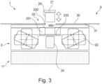
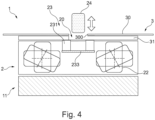
- the filter carrier 232 with the grease filters 230 and the protective grille 21 can be removed upwards from the recess 300. This enables access through the recess 300 and thus the air inlet opening 20 to the other parts of the filter unit 23 and the liquid container 24.
- the odor filters 231 can be removed from the extractor device 2.
- the odor filter 231 to be removed is moved from the position laterally offset from the air inlet opening 20 on the filter guide 233 until it is located below the air inlet opening 20.
- the odor filter 231 can be removed as shown in Figure 6 shown, can be removed upwards through the air inlet opening 20.
- the odor filter(s) 231 can also be removed while the liquid container 24 is still in the extractor device 2.
- the invention thus provides a liquid container which is integrated in the combination device and is arranged in such a way that it can be easily reached and removed by the user.
- the space between the components is used to place the liquid container in which liquids can be collected, for example when food overflows or when liquids are spilled on the hob.
- the fans can be integrated into the combination device in such a way that the axis of the fan wheel is vertical or horizontal or the axis of the fan wheel is at an angle between horizontal and vertical.
- the fans can be independent of each other and the air flow to the fans can also be independent. This means The design becomes more flexible with regard to the placement of the liquid container between the components of the module and with regard to the optimization of the volume of the combination device.
- both the filter unit of the extractor device and the liquid container can be removed through the air inlet opening, which is formed in particular by a recess in the cover plate of the hob.
- the filter unit with grease filter and odor filter can be integrated in the extractor device in such a way that they are easily accessible and can be removed by the user.
- the inventive concept allows the extractor device to be flush with the cover plate of the hob.
- the grease filter is stored in the extractor hood in a removable manner.
- the grease filter can be removed to be washed by the user.
- the filter concept is the conventional concept.
- the filter can be held on profiles that are accommodated in the recess of the cover plate or the filter is held on a holder in the extractor hood.
- the liquid container can be located under the grease filter, which avoids a complex structure with a pipe through which the liquid is currently led to the liquid container.
- the capacity of the liquid container can be in the range of 250ml to 2500ml and depends on the structure and dimensions of the combination device.
- the odor filter is also removable.
- the odor filter is arranged next to the grease filter and is held by a filter guide, which can also be referred to as a guide housing.
- This filter housing preferably allows the odor filters to be moved in the horizontal direction to facilitate access to the odor filter elements.
- the present invention has a number of advantages.
- all parts that can be replaced and washed by the user can be arranged in such a way that they can be removed by the user through the recess in the cover plate of the hob.
- the liquid container can be easily removed by the user using the recess in the top plate to access the container.
- the liquid container which is located between the fans, results in easy maintenance due to accessibility and without the need for a professional to empty it.
- the liquid container is located after the odor filter, which ensures better water protection for the odor filter and also for other parts.
- the construction of the components leading to the container is simpler due to the proximity of the liquid container to the cooking area.
- the filter unit allows the grease filter to be removed and washed.
- the filter unit is improved and allows easy maintenance due to its accessibility and without the need for a specialist to change the odor filter.
- a grille can be flush with the cover plate to provide a continuous appearance and improve the aesthetic appeal of the workspace.
Landscapes
- Engineering & Computer Science (AREA)
- Chemical & Material Sciences (AREA)
- Combustion & Propulsion (AREA)
- Mechanical Engineering (AREA)
- General Engineering & Computer Science (AREA)
- Filtering Of Dispersed Particles In Gases (AREA)
- Ventilation (AREA)
Claims (4)
- Dispositif formant hotte aspirante pour une table de cuisson (3), laquelle présente un orifice d'entrée d'air (20), par lequel l'air est aspiré vers le bas, et au moins un ventilateur (22), dans lequel en dessous de l'orifice d'entrée d'air (20), un récipient à liquide (24) qui collecte les liquides entrant par l'orifice d'entrée d'air (20) est maintenu amovible, les dimensions horizontales du récipient à liquide (24) sont plus petites que les dimensions horizontales correspondantes de l'orifice d'entrée d'air (20), le dispositif formant hotte aspirante (2) présente deux ventilateurs (22), lesquels sont disposés par rapport à l'orifice d'entrée d'air (20) latéralement décalés dans le dispositif formant hotte aspirante (2) et le récipient à liquide se trouve entre les deux ventilateurs (22), caractérisé en ce que dans l'orifice d'entrée d'air (20) est fixée amovible au moins une partie d'une unité filtrante (23),en ce que l'unité filtrante (23) comprend au moins un filtre à graisse (230) et au moins un filtre à odeur (231),en ce que le au moins un filtre à graisse (230) est maintenu dans un support de filtre (232), lequel est logé amovible dans l'orifice d'entrée d'air (20),en ce que le au moins un filtre à odeur (231) est disposé contigu au au moins un filtre à graisse (230) et est maintenu sur un passe-filtre (233),en ce que le passe-filtre est un rail ou une paire de rails qui s'étend en dessous de l'orifice d'entrée d'air à l'horizontale et le passe-filtre (233) présente une largeur plus grande que l'orifice d'entrée d'air (20),en ce que le passe-filtre (233) est logé coulissant ou le au moins un filtre à odeur (231) coulisse sur un passe-filtre (233) gisant, ce qui fait qu'à chaque fois l'un du au moins un filtre à odeur est amené dans une position dans laquelle celui-ci se trouve en dessous de l'orifice d'entrée d'air et peut être sorti vers le haut en passant par l'orifice d'entrée d'air ; en ce que le au moins un filtre à odeur présente une dimension plus petite que la dimension de l'orifice d'entrée d'air,en ce que le récipient à liquide (24) est disposé en dessous de l'unité filtrante (23) eten ce que le récipient à liquide (24) présente un orifice d'entrée d'air qui est prévu sur le côté supérieur du récipient à liquide (24).
- Dispositif formant hotte aspirante selon la revendication 1, caractérisé en ce que le dispositif formant hotte aspirante (2) présente un carter (10), l'orifice d'entrée d'air (20) est disposé dans le côté supérieur du carter (10) et le récipient à liquide (24) est maintenu amovible au fond (100) du carter (10).
- Appareil combiné comprenant une table de cuisson (3) et au moins un dispositif formant hotte aspirante (2) selon l'une des revendications 1 ou 2.
- Appareil combiné selon la revendication 3, caractérisé en ce que la table de cuisson (3) présente une plaque couvrante (30) dans laquelle est pratiqué un évidement (300) et l'évidement (300) forme l'orifice d'entrée d'air (20) du dispositif formant hotte aspirante (2).
Applications Claiming Priority (1)
| Application Number | Priority Date | Filing Date | Title |
|---|---|---|---|
| EP19382280 | 2019-04-12 |
Publications (2)
| Publication Number | Publication Date |
|---|---|
| EP3722677A1 EP3722677A1 (fr) | 2020-10-14 |
| EP3722677B1 true EP3722677B1 (fr) | 2024-07-31 |
Family
ID=66223651
Family Applications (1)
| Application Number | Title | Priority Date | Filing Date |
|---|---|---|---|
| EP20168664.9A Active EP3722677B1 (fr) | 2019-04-12 | 2020-04-08 | Dispositif formant hotte aspirante et appareil combiné pourvu de plaque de cuisson et de dispositif formant hotte aspirante |
Country Status (2)
| Country | Link |
|---|---|
| EP (1) | EP3722677B1 (fr) |
| ES (1) | ES2995433T3 (fr) |
Families Citing this family (7)
| Publication number | Priority date | Publication date | Assignee | Title |
|---|---|---|---|---|
| EP3827204B1 (fr) | 2018-07-24 | 2023-12-06 | Wilhelm Bruckbauer | Système de table de cuisson |
| EP4043797B1 (fr) * | 2021-02-10 | 2025-12-24 | V-Zug AG | Hotte aspirante dans plaque de cuisson |
| DE102022123338A1 (de) * | 2022-09-13 | 2024-03-14 | Berbel Ablufttechnik Gmbh | Dunstabzug und Kombinationsgerät |
| DE102023100335B4 (de) | 2023-01-09 | 2026-02-19 | 3Defacto Gmbh | Kochfeldabzug und Verfahren zum Betreiben eines Kochfeldabzugs |
| DE102023116297A1 (de) * | 2023-06-21 | 2024-12-24 | Berbel Ablufttechnik Gmbh | Dunstabzug und Kombinationsgerät |
| DE102023125203A1 (de) * | 2023-09-18 | 2025-03-20 | Berbel Ablufttechnik Gmbh | Dunstabzug und Kombinationsgerät |
| DE102024204113A1 (de) * | 2024-05-02 | 2025-11-06 | BSH Hausgeräte GmbH | Haushaltsgerätevorrichtung |
Citations (3)
| Publication number | Priority date | Publication date | Assignee | Title |
|---|---|---|---|---|
| WO2017029138A1 (fr) * | 2015-08-19 | 2017-02-23 | BSH Hausgeräte GmbH | Unité filtrante pour un dispositif aspirant et appareil combiné doté d'une plaque de cuisson et d'un dispositif aspirant pourvu d'un élément filtrant |
| WO2017103708A1 (fr) * | 2015-12-18 | 2017-06-22 | Elica S.P.A. | Hotte à usage domestique |
| US20180209662A1 (en) * | 2015-08-19 | 2018-07-26 | BSH Hausgeräte GmbH | Combined device with cooking surface and fume extractor |
Family Cites Families (6)
| Publication number | Priority date | Publication date | Assignee | Title |
|---|---|---|---|---|
| US20070062513A1 (en) * | 2005-09-21 | 2007-03-22 | Gagas John M | Cooking system with ventilator and blower |
| DE202011005698U1 (de) * | 2011-04-28 | 2011-09-26 | Wilhelm Bruckbauer | Kochfeld mit zentraler Absaugung von Kochdünsten nach unten |
| DE202016104283U1 (de) * | 2015-08-07 | 2016-08-09 | Airforce S.P.A. | Vorrichtung zum Filtern von Dünsten und Dämpfen vom Kochen |
| EP3136004B1 (fr) * | 2015-08-19 | 2019-10-09 | BSH Hausgeräte GmbH | Appareil combiné comprenant une plaque de cuisson et un dispositif d'aspiration de fumées |
| DE102017200201A1 (de) | 2017-01-09 | 2018-07-12 | BSH Hausgeräte GmbH | Dunstabzugsvorrichtung und Kombinationsgerät mit Dunstab-zugsvorrichtung |
| DE102017217853B4 (de) * | 2017-10-06 | 2022-07-07 | Wilhelm Bruckbauer | Kochfeldsystem mit Dunstabzugsvorrichtung |
-
2020
- 2020-04-08 ES ES20168664T patent/ES2995433T3/es active Active
- 2020-04-08 EP EP20168664.9A patent/EP3722677B1/fr active Active
Patent Citations (3)
| Publication number | Priority date | Publication date | Assignee | Title |
|---|---|---|---|---|
| WO2017029138A1 (fr) * | 2015-08-19 | 2017-02-23 | BSH Hausgeräte GmbH | Unité filtrante pour un dispositif aspirant et appareil combiné doté d'une plaque de cuisson et d'un dispositif aspirant pourvu d'un élément filtrant |
| US20180209662A1 (en) * | 2015-08-19 | 2018-07-26 | BSH Hausgeräte GmbH | Combined device with cooking surface and fume extractor |
| WO2017103708A1 (fr) * | 2015-12-18 | 2017-06-22 | Elica S.P.A. | Hotte à usage domestique |
Also Published As
| Publication number | Publication date |
|---|---|
| EP3722677A1 (fr) | 2020-10-14 |
| ES2995433T3 (en) | 2025-02-10 |
Similar Documents
| Publication | Publication Date | Title |
|---|---|---|
| EP3722677A1 (fr) | Dispositif formant hotte aspirante et appareil combiné pourvu de plaque de cuisson et de dispositif formant hotte aspirante | |
| EP3701192B1 (fr) | Appareil combiné comprenant un dispositif d'aspiration de fumées et une plaque de cuisson | |
| EP4474718A2 (fr) | Appareil combiné comprenant un dispositif d'aspiration des fumées et une table de cuisson | |
| EP3789682A1 (fr) | Unité de filtre et dispositif formant hotte aspirante pourvu d'unité de filtre | |
| DE20117490U1 (de) | Luftabsaugvorrichtung für einen Arbeitsplatz | |
| EP3290813A1 (fr) | Dispositif d'évacuation de vapeurs et appareil combiné pourvu de dispositif d'évacuation de vapeurs | |
| EP3133349B1 (fr) | Unité combinée comprenant une zone de cuisson et un dispositif d'aspiration de fumée comprenant une unité de filtration | |
| DE102018215480A1 (de) | Dunstabzugsvorrichtung mit Verschlussklappe | |
| DE102018221339A1 (de) | Dunstabzugsvorrichtung, Küchengerät mit Kochfeld und Dunstabzugsvorrichtung und Verfahren zum Betreiben einer Dunstabzugsvorrichtung | |
| DE102020210578A1 (de) | Dunstabzugsvorrichtung und Kombinationsgerät | |
| EP3502572B1 (fr) | Dispositif d'évacuation de fumée, appareil de cuisine pourvu de plaque de cuisson et dispositif d'évacuation de fumée et procédé de fonctionnement d'un dispositif d'évacuation de fumée | |
| EP3956611B1 (fr) | Dispositif de filtrage pour un dispositif d'extraction de fumées et dispositif d'extraction de fumées avec dispositif de filtrage | |
| EP3336438B1 (fr) | Hotte aspirante | |
| EP4036482B1 (fr) | Dispositif par-vapeur, aérateur à tirage descendant et procédé de maintenance | |
| DE102007055308A1 (de) | Filtervorrichtung | |
| EP3789681B1 (fr) | Dispositif formant hotte aspirante et appareil combiné | |
| DE202015104362U1 (de) | Dunstabzugshaube für eine Fritteuse | |
| EP3346195B1 (fr) | Système de filtre pour hotte aspirante et hotte aspirante | |
| DE102017200201A1 (de) | Dunstabzugsvorrichtung und Kombinationsgerät mit Dunstab-zugsvorrichtung | |
| EP2554917B1 (fr) | Dispositif d'aspiration d'air pour une table de cuisson | |
| EP3517844B1 (fr) | Hotte aspirante | |
| EP4151909B1 (fr) | Module de table de cuisson | |
| EP3222919A1 (fr) | Hotte aspirante comprenant un couvercle transparent et élément interne | |
| EP3926242B1 (fr) | Unité de filtre et hotte aspirante | |
| DE102018119698A1 (de) | Dunstabzugssystem für Kochfelder |
Legal Events
| Date | Code | Title | Description |
|---|---|---|---|
| PUAI | Public reference made under article 153(3) epc to a published international application that has entered the european phase |
Free format text: ORIGINAL CODE: 0009012 |
|
| STAA | Information on the status of an ep patent application or granted ep patent |
Free format text: STATUS: THE APPLICATION HAS BEEN PUBLISHED |
|
| AK | Designated contracting states |
Kind code of ref document: A1 Designated state(s): AL AT BE BG CH CY CZ DE DK EE ES FI FR GB GR HR HU IE IS IT LI LT LU LV MC MK MT NL NO PL PT RO RS SE SI SK SM TR |
|
| AX | Request for extension of the european patent |
Extension state: BA ME |
|
| STAA | Information on the status of an ep patent application or granted ep patent |
Free format text: STATUS: REQUEST FOR EXAMINATION WAS MADE |
|
| 17P | Request for examination filed |
Effective date: 20210414 |
|
| RBV | Designated contracting states (corrected) |
Designated state(s): AL AT BE BG CH CY CZ DE DK EE ES FI FR GB GR HR HU IE IS IT LI LT LU LV MC MK MT NL NO PL PT RO RS SE SI SK SM TR |
|
| STAA | Information on the status of an ep patent application or granted ep patent |
Free format text: STATUS: EXAMINATION IS IN PROGRESS |
|
| 17Q | First examination report despatched |
Effective date: 20230207 |
|
| TPAC | Observations filed by third parties |
Free format text: ORIGINAL CODE: EPIDOSNTIPA |
|
| GRAP | Despatch of communication of intention to grant a patent |
Free format text: ORIGINAL CODE: EPIDOSNIGR1 |
|
| STAA | Information on the status of an ep patent application or granted ep patent |
Free format text: STATUS: GRANT OF PATENT IS INTENDED |
|
| INTG | Intention to grant announced |
Effective date: 20240318 |
|
| GRAS | Grant fee paid |
Free format text: ORIGINAL CODE: EPIDOSNIGR3 |
|
| GRAA | (expected) grant |
Free format text: ORIGINAL CODE: 0009210 |
|
| STAA | Information on the status of an ep patent application or granted ep patent |
Free format text: STATUS: THE PATENT HAS BEEN GRANTED |
|
| AK | Designated contracting states |
Kind code of ref document: B1 Designated state(s): AL AT BE BG CH CY CZ DE DK EE ES FI FR GB GR HR HU IE IS IT LI LT LU LV MC MK MT NL NO PL PT RO RS SE SI SK SM TR |
|
| REG | Reference to a national code |
Ref country code: CH Ref legal event code: EP Ref country code: GB Ref legal event code: FG4D Free format text: NOT ENGLISH |
|
| REG | Reference to a national code |
Ref country code: DE Ref legal event code: R096 Ref document number: 502020008709 Country of ref document: DE |
|
| REG | Reference to a national code |
Ref country code: IE Ref legal event code: FG4D Free format text: LANGUAGE OF EP DOCUMENT: GERMAN |
|
| REG | Reference to a national code |
Ref country code: NL Ref legal event code: FP |
|
| REG | Reference to a national code |
Ref country code: LT Ref legal event code: MG9D |
|
| PG25 | Lapsed in a contracting state [announced via postgrant information from national office to epo] |
Ref country code: PT Free format text: LAPSE BECAUSE OF FAILURE TO SUBMIT A TRANSLATION OF THE DESCRIPTION OR TO PAY THE FEE WITHIN THE PRESCRIBED TIME-LIMIT Effective date: 20241202 |
|
| PG25 | Lapsed in a contracting state [announced via postgrant information from national office to epo] |
Ref country code: PT Free format text: LAPSE BECAUSE OF FAILURE TO SUBMIT A TRANSLATION OF THE DESCRIPTION OR TO PAY THE FEE WITHIN THE PRESCRIBED TIME-LIMIT Effective date: 20241202 |
|
| PG25 | Lapsed in a contracting state [announced via postgrant information from national office to epo] |
Ref country code: NO Free format text: LAPSE BECAUSE OF FAILURE TO SUBMIT A TRANSLATION OF THE DESCRIPTION OR TO PAY THE FEE WITHIN THE PRESCRIBED TIME-LIMIT Effective date: 20241031 |
|
| PG25 | Lapsed in a contracting state [announced via postgrant information from national office to epo] |
Ref country code: FI Free format text: LAPSE BECAUSE OF FAILURE TO SUBMIT A TRANSLATION OF THE DESCRIPTION OR TO PAY THE FEE WITHIN THE PRESCRIBED TIME-LIMIT Effective date: 20240731 Ref country code: PL Free format text: LAPSE BECAUSE OF FAILURE TO SUBMIT A TRANSLATION OF THE DESCRIPTION OR TO PAY THE FEE WITHIN THE PRESCRIBED TIME-LIMIT Effective date: 20240731 Ref country code: GR Free format text: LAPSE BECAUSE OF FAILURE TO SUBMIT A TRANSLATION OF THE DESCRIPTION OR TO PAY THE FEE WITHIN THE PRESCRIBED TIME-LIMIT Effective date: 20241101 |
|
| PG25 | Lapsed in a contracting state [announced via postgrant information from national office to epo] |
Ref country code: BG Free format text: LAPSE BECAUSE OF FAILURE TO SUBMIT A TRANSLATION OF THE DESCRIPTION OR TO PAY THE FEE WITHIN THE PRESCRIBED TIME-LIMIT Effective date: 20240731 |
|
| PG25 | Lapsed in a contracting state [announced via postgrant information from national office to epo] |
Ref country code: LV Free format text: LAPSE BECAUSE OF FAILURE TO SUBMIT A TRANSLATION OF THE DESCRIPTION OR TO PAY THE FEE WITHIN THE PRESCRIBED TIME-LIMIT Effective date: 20240731 |
|
| PG25 | Lapsed in a contracting state [announced via postgrant information from national office to epo] |
Ref country code: IS Free format text: LAPSE BECAUSE OF FAILURE TO SUBMIT A TRANSLATION OF THE DESCRIPTION OR TO PAY THE FEE WITHIN THE PRESCRIBED TIME-LIMIT Effective date: 20241130 |
|
| PG25 | Lapsed in a contracting state [announced via postgrant information from national office to epo] |
Ref country code: HR Free format text: LAPSE BECAUSE OF FAILURE TO SUBMIT A TRANSLATION OF THE DESCRIPTION OR TO PAY THE FEE WITHIN THE PRESCRIBED TIME-LIMIT Effective date: 20240731 |
|
| PG25 | Lapsed in a contracting state [announced via postgrant information from national office to epo] |
Ref country code: RS Free format text: LAPSE BECAUSE OF FAILURE TO SUBMIT A TRANSLATION OF THE DESCRIPTION OR TO PAY THE FEE WITHIN THE PRESCRIBED TIME-LIMIT Effective date: 20241031 |
|
| PG25 | Lapsed in a contracting state [announced via postgrant information from national office to epo] |
Ref country code: RS Free format text: LAPSE BECAUSE OF FAILURE TO SUBMIT A TRANSLATION OF THE DESCRIPTION OR TO PAY THE FEE WITHIN THE PRESCRIBED TIME-LIMIT Effective date: 20241031 Ref country code: PL Free format text: LAPSE BECAUSE OF FAILURE TO SUBMIT A TRANSLATION OF THE DESCRIPTION OR TO PAY THE FEE WITHIN THE PRESCRIBED TIME-LIMIT Effective date: 20240731 Ref country code: NO Free format text: LAPSE BECAUSE OF FAILURE TO SUBMIT A TRANSLATION OF THE DESCRIPTION OR TO PAY THE FEE WITHIN THE PRESCRIBED TIME-LIMIT Effective date: 20241031 Ref country code: LV Free format text: LAPSE BECAUSE OF FAILURE TO SUBMIT A TRANSLATION OF THE DESCRIPTION OR TO PAY THE FEE WITHIN THE PRESCRIBED TIME-LIMIT Effective date: 20240731 Ref country code: IS Free format text: LAPSE BECAUSE OF FAILURE TO SUBMIT A TRANSLATION OF THE DESCRIPTION OR TO PAY THE FEE WITHIN THE PRESCRIBED TIME-LIMIT Effective date: 20241130 Ref country code: HR Free format text: LAPSE BECAUSE OF FAILURE TO SUBMIT A TRANSLATION OF THE DESCRIPTION OR TO PAY THE FEE WITHIN THE PRESCRIBED TIME-LIMIT Effective date: 20240731 Ref country code: GR Free format text: LAPSE BECAUSE OF FAILURE TO SUBMIT A TRANSLATION OF THE DESCRIPTION OR TO PAY THE FEE WITHIN THE PRESCRIBED TIME-LIMIT Effective date: 20241101 Ref country code: FI Free format text: LAPSE BECAUSE OF FAILURE TO SUBMIT A TRANSLATION OF THE DESCRIPTION OR TO PAY THE FEE WITHIN THE PRESCRIBED TIME-LIMIT Effective date: 20240731 Ref country code: BG Free format text: LAPSE BECAUSE OF FAILURE TO SUBMIT A TRANSLATION OF THE DESCRIPTION OR TO PAY THE FEE WITHIN THE PRESCRIBED TIME-LIMIT Effective date: 20240731 |
|
| REG | Reference to a national code |
Ref country code: ES Ref legal event code: FG2A Ref document number: 2995433 Country of ref document: ES Kind code of ref document: T3 Effective date: 20250210 |
|
| PG25 | Lapsed in a contracting state [announced via postgrant information from national office to epo] |
Ref country code: DK Free format text: LAPSE BECAUSE OF FAILURE TO SUBMIT A TRANSLATION OF THE DESCRIPTION OR TO PAY THE FEE WITHIN THE PRESCRIBED TIME-LIMIT Effective date: 20240731 Ref country code: RO Free format text: LAPSE BECAUSE OF FAILURE TO SUBMIT A TRANSLATION OF THE DESCRIPTION OR TO PAY THE FEE WITHIN THE PRESCRIBED TIME-LIMIT Effective date: 20240731 Ref country code: SM Free format text: LAPSE BECAUSE OF FAILURE TO SUBMIT A TRANSLATION OF THE DESCRIPTION OR TO PAY THE FEE WITHIN THE PRESCRIBED TIME-LIMIT Effective date: 20240731 |
|
| PG25 | Lapsed in a contracting state [announced via postgrant information from national office to epo] |
Ref country code: EE Free format text: LAPSE BECAUSE OF FAILURE TO SUBMIT A TRANSLATION OF THE DESCRIPTION OR TO PAY THE FEE WITHIN THE PRESCRIBED TIME-LIMIT Effective date: 20240731 |
|
| PG25 | Lapsed in a contracting state [announced via postgrant information from national office to epo] |
Ref country code: CZ Free format text: LAPSE BECAUSE OF FAILURE TO SUBMIT A TRANSLATION OF THE DESCRIPTION OR TO PAY THE FEE WITHIN THE PRESCRIBED TIME-LIMIT Effective date: 20240731 |
|
| PG25 | Lapsed in a contracting state [announced via postgrant information from national office to epo] |
Ref country code: SK Free format text: LAPSE BECAUSE OF FAILURE TO SUBMIT A TRANSLATION OF THE DESCRIPTION OR TO PAY THE FEE WITHIN THE PRESCRIBED TIME-LIMIT Effective date: 20240731 Ref country code: IT Free format text: LAPSE BECAUSE OF FAILURE TO SUBMIT A TRANSLATION OF THE DESCRIPTION OR TO PAY THE FEE WITHIN THE PRESCRIBED TIME-LIMIT Effective date: 20240731 |
|
| REG | Reference to a national code |
Ref country code: DE Ref legal event code: R097 Ref document number: 502020008709 Country of ref document: DE |
|
| PGFP | Annual fee paid to national office [announced via postgrant information from national office to epo] |
Ref country code: NL Payment date: 20250422 Year of fee payment: 6 |
|
| PLBE | No opposition filed within time limit |
Free format text: ORIGINAL CODE: 0009261 |
|
| STAA | Information on the status of an ep patent application or granted ep patent |
Free format text: STATUS: NO OPPOSITION FILED WITHIN TIME LIMIT |
|
| 26N | No opposition filed |
Effective date: 20250501 |
|
| PGFP | Annual fee paid to national office [announced via postgrant information from national office to epo] |
Ref country code: DE Payment date: 20250430 Year of fee payment: 6 |
|
| PGFP | Annual fee paid to national office [announced via postgrant information from national office to epo] |
Ref country code: ES Payment date: 20250519 Year of fee payment: 6 |
|
| PGFP | Annual fee paid to national office [announced via postgrant information from national office to epo] |
Ref country code: FR Payment date: 20250428 Year of fee payment: 6 |
|
| PG25 | Lapsed in a contracting state [announced via postgrant information from national office to epo] |
Ref country code: SE Free format text: LAPSE BECAUSE OF FAILURE TO SUBMIT A TRANSLATION OF THE DESCRIPTION OR TO PAY THE FEE WITHIN THE PRESCRIBED TIME-LIMIT Effective date: 20240731 |
|
| REG | Reference to a national code |
Ref country code: CH Ref legal event code: H13 Free format text: ST27 STATUS EVENT CODE: U-0-0-H10-H13 (AS PROVIDED BY THE NATIONAL OFFICE) Effective date: 20251125 |
|
| PG25 | Lapsed in a contracting state [announced via postgrant information from national office to epo] |
Ref country code: LU Free format text: LAPSE BECAUSE OF NON-PAYMENT OF DUE FEES Effective date: 20250408 |
|
| PG25 | Lapsed in a contracting state [announced via postgrant information from national office to epo] |
Ref country code: MC Free format text: LAPSE BECAUSE OF FAILURE TO SUBMIT A TRANSLATION OF THE DESCRIPTION OR TO PAY THE FEE WITHIN THE PRESCRIBED TIME-LIMIT Effective date: 20240731 |
|
| REG | Reference to a national code |
Ref country code: BE Ref legal event code: MM Effective date: 20250430 |
|
| PG25 | Lapsed in a contracting state [announced via postgrant information from national office to epo] |
Ref country code: BE Free format text: LAPSE BECAUSE OF NON-PAYMENT OF DUE FEES Effective date: 20250430 |
|
| PG25 | Lapsed in a contracting state [announced via postgrant information from national office to epo] |
Ref country code: CH Free format text: LAPSE BECAUSE OF NON-PAYMENT OF DUE FEES Effective date: 20250430 |
|
| PGFP | Annual fee paid to national office [announced via postgrant information from national office to epo] |
Ref country code: GB Payment date: 20260324 Year of fee payment: 7 |
|
| PG25 | Lapsed in a contracting state [announced via postgrant information from national office to epo] |
Ref country code: IE Free format text: LAPSE BECAUSE OF NON-PAYMENT OF DUE FEES Effective date: 20250408 |