EP3722724B1 - Flüssigkeitsdichte verbindung für wärmetauscher und wärmetauscher, der eine solche verbindung enthält. - Google Patents
Flüssigkeitsdichte verbindung für wärmetauscher und wärmetauscher, der eine solche verbindung enthält. Download PDFInfo
- Publication number
- EP3722724B1 EP3722724B1 EP19398004.2A EP19398004A EP3722724B1 EP 3722724 B1 EP3722724 B1 EP 3722724B1 EP 19398004 A EP19398004 A EP 19398004A EP 3722724 B1 EP3722724 B1 EP 3722724B1
- Authority
- EP
- European Patent Office
- Prior art keywords
- plate
- jacket
- plates
- fluid
- heat exchanger
- Prior art date
- Legal status (The legal status is an assumption and is not a legal conclusion. Google has not performed a legal analysis and makes no representation as to the accuracy of the status listed.)
- Active
Links
Images

Classifications
-
- F—MECHANICAL ENGINEERING; LIGHTING; HEATING; WEAPONS; BLASTING
- F28—HEAT EXCHANGE IN GENERAL
- F28D—HEAT-EXCHANGE APPARATUS, NOT PROVIDED FOR IN ANOTHER SUBCLASS, IN WHICH THE HEAT-EXCHANGE MEDIA DO NOT COME INTO DIRECT CONTACT
- F28D7/00—Heat-exchange apparatus having stationary tubular conduit assemblies for both heat-exchange media, the media being in contact with different sides of a conduit wall
- F28D7/16—Heat-exchange apparatus having stationary tubular conduit assemblies for both heat-exchange media, the media being in contact with different sides of a conduit wall the conduits being arranged in parallel spaced relation
- F28D7/1684—Heat-exchange apparatus having stationary tubular conduit assemblies for both heat-exchange media, the media being in contact with different sides of a conduit wall the conduits being arranged in parallel spaced relation the conduits having a non-circular cross-section
-
- F—MECHANICAL ENGINEERING; LIGHTING; HEATING; WEAPONS; BLASTING
- F02—COMBUSTION ENGINES; HOT-GAS OR COMBUSTION-PRODUCT ENGINE PLANTS
- F02B—INTERNAL-COMBUSTION PISTON ENGINES; COMBUSTION ENGINES IN GENERAL
- F02B29/00—Engines characterised by provision for charging or scavenging not provided for in groups F02B25/00, F02B27/00 or F02B33/00 - F02B39/00; Details thereof
- F02B29/04—Cooling of air intake supply
- F02B29/045—Constructional details of the heat exchangers, e.g. pipes, plates, ribs, insulation, materials, or manufacturing and assembly
- F02B29/0462—Liquid cooled heat exchangers
-
- F—MECHANICAL ENGINEERING; LIGHTING; HEATING; WEAPONS; BLASTING
- F28—HEAT EXCHANGE IN GENERAL
- F28F—DETAILS OF HEAT-EXCHANGE AND HEAT-TRANSFER APPARATUS, OF GENERAL APPLICATION
- F28F9/00—Casings; Header boxes; Auxiliary supports for elements; Auxiliary members within casings
- F28F9/001—Casings in the form of plate-like arrangements; Frames enclosing a heat exchange core
-
- F—MECHANICAL ENGINEERING; LIGHTING; HEATING; WEAPONS; BLASTING
- F28—HEAT EXCHANGE IN GENERAL
- F28D—HEAT-EXCHANGE APPARATUS, NOT PROVIDED FOR IN ANOTHER SUBCLASS, IN WHICH THE HEAT-EXCHANGE MEDIA DO NOT COME INTO DIRECT CONTACT
- F28D21/00—Heat-exchange apparatus not covered by any of the groups F28D1/00 - F28D20/00
- F28D2021/0019—Other heat exchangers for particular applications; Heat exchange systems not otherwise provided for
- F28D2021/008—Other heat exchangers for particular applications; Heat exchange systems not otherwise provided for for vehicles
- F28D2021/0082—Charged air coolers
-
- F—MECHANICAL ENGINEERING; LIGHTING; HEATING; WEAPONS; BLASTING
- F28—HEAT EXCHANGE IN GENERAL
- F28F—DETAILS OF HEAT-EXCHANGE AND HEAT-TRANSFER APPARATUS, OF GENERAL APPLICATION
- F28F2265/00—Safety or protection arrangements; Arrangements for preventing malfunction
- F28F2265/16—Safety or protection arrangements; Arrangements for preventing malfunction for preventing leakage
-
- F—MECHANICAL ENGINEERING; LIGHTING; HEATING; WEAPONS; BLASTING
- F28—HEAT EXCHANGE IN GENERAL
- F28F—DETAILS OF HEAT-EXCHANGE AND HEAT-TRANSFER APPARATUS, OF GENERAL APPLICATION
- F28F2275/00—Fastening; Joining
- F28F2275/04—Fastening; Joining by brazing
-
- Y—GENERAL TAGGING OF NEW TECHNOLOGICAL DEVELOPMENTS; GENERAL TAGGING OF CROSS-SECTIONAL TECHNOLOGIES SPANNING OVER SEVERAL SECTIONS OF THE IPC; TECHNICAL SUBJECTS COVERED BY FORMER USPC CROSS-REFERENCE ART COLLECTIONS [XRACs] AND DIGESTS
- Y02—TECHNOLOGIES OR APPLICATIONS FOR MITIGATION OR ADAPTATION AGAINST CLIMATE CHANGE
- Y02T—CLIMATE CHANGE MITIGATION TECHNOLOGIES RELATED TO TRANSPORTATION
- Y02T10/00—Road transport of goods or passengers
- Y02T10/10—Internal combustion engine [ICE] based vehicles
- Y02T10/12—Improving ICE efficiencies
Definitions
- the present invention relates generally to heat exchangers, particularly for automotive applications.
- WCACs water cooled charge air coolers
- WCACs are commonly used in intake systems of internal combustion engines.
- a water-based mixture is circulated through a jacket of the WCAC, which is connected to a water circuit.
- the water-based mixture passing through the jacket is used to cool down a gaseous fluid (air or gaseous mixture) conveyed by the tubes of the WCAC towards the intake system of the internal combustion engine.
- the role of the jacket is therefore to keep the liquid contained in the WCAC.
- the main difficulty of such a design is to seal the liquid side of the WCAC, in particular where the jacket joins to the core plates.
- EP 2 628 896 A2 discloses a heat exchanger comprising a plurality of parallel tubes, a pair of core plates, and a jacket connected to the core plates and defining with the core plates an inner volume for receiving a fluid.
- the tubes are placed within the inner volume.
- the jacket comprises a pair of opposite jacket plates.
- One aim of the invention is to provide a solution that is capable of efficiently sealing the liquid side of WCACs.
- a further aim of the invention is to provide a solution for a fluid-tight joint for a heat exchanger where different components of the heat exchanger are brazed to each other to form a corner structure.
- the invention proposes a fluid-tight joint for a heat exchanger according to claim 1.
- the present invention provides an efficient solution to the problem of sealing liquid side of the WCAC where the jacket joins to the core plate.
- the jacket plates in their corners are deformed so that the geometry on the said corners matches the geometry of the adjacent components to which they braze, i.e., the side plate and core plate. This matching geometry allows for an easy brazing of the three components (jacket plate, side plate and core plate) without the need for addition of material.
- the invention is mainly aimed at water cooled charge air coolers, but it can be used similarly on other liquid to gas heat exchangers or even on liquid to liquid heat exchangers where at least one of the circuits needs to be sealed off from the environment.
- each jacket plate is overlapping with the side plates, respectively, and the end flaps of each jacket plate are overlapping with the core plates, respectively.
- each jacket plate are brazed to the side plates, respectively, the end flaps of each jacket plate are brazed to the core plates, respectively, and the tongues of each side plate are brazed to the core plates, respectively.
- a method for producing a plate for a fluid-tight joint not covered by the claimed invention comprises the following steps
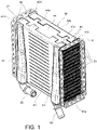
- a heat exchanger such as for example a water charge air cooler, is shown in the drawings.
- the heat exchanger comprises an inlet core plate 11 and an outlet core plate 21, both of metal material, such as for example aluminium.
- These core plates 11 and 21 are intended to be connected in a known way to an inlet header tank (not shown) and to an outlet header tank (not shown), respectively.
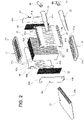
- the heat exchanger 1 further comprises a core 30 comprising a plurality of parallel flat tubes 31 extending between the core plates 11 and 21, one of which tubes is also individually shown in Figure 2 .
- the tubes 31 are of metal material, such as for example aluminium.
- Each tube 31 has opposite ends inserted into openings or slots formed in one or the other of the core plates 11, 21, respectively.
- Each tube 31 has an approximately rectangular cross-section, and comprises a pair of opposite long sidewalls and a pair of opposite short sidewalls which interconnect the long sidewalls and are shorter than the long sidewalls.
- a respective finned plate 31a Within each tube 31, there is arranged a respective finned plate 31a.
- a first fluid particularly a gaseous fluid such as, for example, air or a gaseous mixture
- a gaseous fluid such as, for example, air or a gaseous mixture
- the heat exchanger can be connected to a fluid circuit for the first fluid (not shown), comprising for example an intake system of an internal combustion engine.
- a second fluid particularly a liquid coolant such as, for example, water or a water-based mixture, is designed to flow around the core 30 and through gaps between the tubes 31, and exchange heat with the first fluid flowing into the tubes 31.
- Finned plates 32 are arranged into the gaps between the tubes 31, as well as adjacent to tubes 31 at opposite ends of the core 30.
- the heat exchanger further comprises a jacket 40 of metal material, such as for example aluminium.
- the jacket 40 is connected to the core plates 11 and 21 in a fluid-tight manner and defines with the core plates 11 and 21 an inner volume for receiving/conveying the second fluid.
- the tubes 31 are placed within this inner volume formed by the jacket 40 and the core plates 11 and 21.
- the jacket 40 has a rectangular cross-section and comprises a pair of opposite jacket plates 41 and 42 and a pair of opposite side plates 43 and 44 to which the jacket plates 41 and 42 are connected.
- the heat exchanger further comprises an inlet fluid channel 51 and an outlet fluid channel 61 for conveying the second fluid to and from the inner volume formed by the jacket 40 along with the core plates 11, 21.
- Both fluid channels 51, 61 are of metal material, such as for example aluminium.
- Each fluid channel 51, 61 is joined to a wall of the jacket 40.
- both fluid channels 51, 61 are joined to one of the jacket plates referenced with 41.
- each fluid channel 51, 61 is formed as an elongate, concave shell, whose rim is joined to the jacket plate.
- Each fluid channel 51, 61 is in fluid communication with the inner volume of the jacket 40 through a respective opening 53, 63 formed through the wall 41 of the jacket 40.
- Figure 2 also shows inlet and outlet fluid connectors, 55 and 65, which are fixed to the inlet fluid channel 51 and the outlet fluid channel 61, respectively, to connect the heat exchanger to a fluid circuit for the second fluid (not shown), such as for example a liquid coolant circuit.
- a fluid circuit for the second fluid such as for example a liquid coolant circuit.
- the tubes 31, core plates 11 and 21, and jacket 40 are joined to each other, fluid channels 51 and 61 are joined to the jacket 40, and connectors 55 and 65 are joined to the fluid channels 51 and 61 in a conventional manner, particularly by brazing.
- tubes 31 and finned plates 32 are stacked with side plates 43, 44 at the top and bottom and core plates 11, 21 on the sides in order to obtain a sub-assembly.
- the jacket plates 41, 42 are placed over the sub-assembly.
- the sub-assembly and the jacket plates are held together with jigs and joined to each other by brazing. When the brazing process is completed, the jigs are removed.
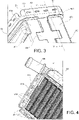
- Each jacket plate 41, 42 comprises a pair of opposite, inwardly folded side flaps 41a, 41b; 42a, 42b joined to the side plates 43 and 44, respectively, and a pair of opposite, outwardly folded end flaps 41c, 41d; 42c, 42d joined to the core plates 11 and 21, respectively.
- the side flaps 41a, 41b; 42a, 42b of each jacket plate 41, 42 are overlapping with the side plates 43 and 44, respectively, and the end flaps 41c, 41d; 42c, 42d of each jacket plate 41, 42 are overlapping with the core plates 11 and 21, respectively.
- each end flap 41c, 41d; 42c, 42d extends over the main body as well as over the side flaps 41a, 41b; 42a, 42b of the respective jacket plate 41, 42. Therefore, each flap 41c, 41d; 42c, 42d is substantially C-shaped when viewed in plan view.
- Each side plate 43, 44 comprises a pair of end tongues 43a, 43b; 44a, 44b inserted in a fluid-tight manner into respective slots 11a, lib; 21a, 21b formed through the core plates 11 and 21, respectively.
- One of the tongue-slot connections is shown in Figure 4 .
- this joint may be applied to any liquid to gas heat exchangers or even to liquid to liquid heat exchangers where at least one of the circuits needs to be sealed off from the environment. Therefore, in the following description the core plate will be designated as first plate, the side plate will be designated as second plate, and the side flap of the jacket plate will be designated as third plate.
- a slot (11a, 11b, 21a or 21b) is formed through the first plate (11 or 21).
- the second plate (43 or 44) has an end (43a, 43b, 44a or 44b) inserted in a fluid-tight manner into the slot (11a, 11b, 21a or 21b) and brazed to the first plate (11 or 21).
- the third plate (41a, 41b, 42a or 42b) comprises a folded flap (41c, 41d, 42c or 42d).
- the third plate (41a, 41b, 42a or 42b) is overlapping with, and is brazed to the second plate (43 or 44), and the flap (41c, 41d, 42c or 42d) is overlapping with, and is brazed to the first plate (11 or 21).
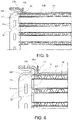
- an area of the third plate (41a, 41b, 42a or 42b) at a corner between the folded flap (41c, 41d, 42c or 42d) and the third plate (41a, 41b, 42a or 42b), hereinafter third plate corner, is deformed to form a recess 51 into the thickness of the third plate (41a, 41b, 42a or 42b), and an outer side of the third plate corner is deformed to match a corner between the second plate (43 or 44) and the first plate (11 or 21).
- Figures 7-9 show a method for obtaining such a deformation into the third plate (41a, 41b, 42a or 42b).
- the third plate (41a, 41b, 42a or 42b) is bent to produce a 90 degrees bend, i.e. the folded flap (41c, 41d, 42c or 42d).
- This bending step may be performed with a press stamping process through a die D and punch P1.
- the third plate (41a, 41b, 42a or 42b) is subjected to a second press stamping step, using a second punch P2 having a wedge-shaped projection W.
- the wedge-shaped projection W applies a local deformation to the third plate (41a, 41b, 42a or 42b), located at the third plate corner, in order to produce the recess 51 on the inner side of the corner, and reduce the curvature radius of the outer side of the third plate corner (see Figure 9 ).
- the recess 51 is decreasing in depth d from the third plate corner towards the remaining part of the third plate (41a, 41b, 42a or 42b).
- the curvature radius R of the outer side of the third plate corner may have a nominal value of 0,2 mm.
- the deformation of the third plate allows the geometry of the third plate corner to match the second plate and first plate shape, to match the side plate and core plate shape. This makes the gap between the three components as small as possible thus improving the brazeability of the joint.
Landscapes
- Engineering & Computer Science (AREA)
- Physics & Mathematics (AREA)
- Thermal Sciences (AREA)
- Mechanical Engineering (AREA)
- General Engineering & Computer Science (AREA)
- Chemical & Material Sciences (AREA)
- Combustion & Propulsion (AREA)
- Heat-Exchange Devices With Radiators And Conduit Assemblies (AREA)
Claims (5)
- Fluiddichtes Verbindungsstück (50) für einen Wärmetauscher, aufweisendeine erste Platte (11, 21), durch welche ein Langloch (11a, 11b, 21a, 21b) ausgebildet ist,eine zweite Platte (43, 44) mit einem Ende (43a, 43b, 44a, 44b), das in fluiddichter Weise in das Langloch eingeführt und an die erste Platte (11, 21) angelötet ist, undeine dritte Platte (41a, 41b, 42a, 42b), aufweisend eine Faltklappe (41c, 41d, 42c, 42d), wobei die dritte Platte (41a, 41b, 42a, 42b) die zweite Platte (43, 44) überlappt und an diese angelötet ist und die Klappe (41c, 41d, 42c, 42d) die erste Platte (11, 21) überlappt und an diese angelötet ist,wobeiein Bereich der dritten Platte (41a, 41b, 42a, 42b) in einer Ecke zwischen der Faltklappe (41c, 41d, 42c, 42d) und der dritten Platte (41a, 41b, 42a, 42b), nachfolgend Dritte-Platten-Ecke, verformt wird, um eine Aussparung (51) in dem dicksten Bereich der dritten Platte (41a, 41b, 42a, 42b) zu bilden, wobei eine Außenseite der Dritte-Platten-Ecke verformt wird, um zu einer Ecke zwischen der zweiten Platte (43, 44) und der ersten Platte (11, 21) zu passen.
- Verbindungsstück nach Anspruch 1, wobei die Aussparung von der Dritte-Platten-Ecke zu der dritten Platte (41a, 41b, 42a, 42b) hin in ihrer Tiefe (d) abnimmt.
- Wärmetauscher, aufweisend ein Verbindungsstück nach einem der Ansprüche 1 bis 2, wobei die erste Platte (11, 21) eine Trägerplatte des Wärmetauschers ist, die zweite Platte (43, 44) eine Seitenplatte des Wärmetauschers ist und die dritte Platte (41a, 41b, 42a, 42b) eine Mantelplatte des Wärmetauschers ist.
- Wärmetauscher, aufweisend:eine Vielzahl paralleler Rohre (31) zum Befördern eines ersten Fluids,ein Paar Trägerplatten (11, 21), welche jeweils eine Vielzahl von Öffnungen aufweisen, in welche jeweilige Enden der Rohre in fluiddichter Weise eingeführt werden,einen Mantel (40), der in fluiddichter Weise mit den Trägerplatten (11, 21) verbunden ist und der mit den Trägerplatten (11, 21) ein Innenvolumen zur Aufnahme eines zweiten Fluids definiert, wobei die Rohre (31) innerhalb des Innenvolumens angeordnet sind,wobei der Mantel ein Paar gegenüberliegender Mantelplatten (41, 42) und ein Paar gegenüberliegender Seitenplatten (43, 44) aufweist, wobei jede der Mantelplatten ein Paar gegenüberliegender nach innen gefalteter, jeweils mit den Seitenplatten (43, 44) verbundener Seitenklappen (41a, 41b, 42a, 42b) und ein Paar gegenüberliegender, nach außen gefalteter, jeweils mit den Trägerplatten (11, 21) verbundener Endklappen (41c, 41d, 42c, 42d) aufweist, undwobei jede der Seitenplatten ein Paar Endlaschen (43a, 43b, 44a, 44b) aufweist, die in fluiddichter Weise in jeweilige Langlöcher (11a, 11b, 21a, 21b) eingefügt werden, welche jeweils durch die Kernplatten (11, 21) ausgeformt sind,wobei der Wärmetauscher mindestens ein Verbindungsstück nach einem der Ansprüche 1 bis 2 aufweist, wobei mindestens eine der Trägerplatten die erste Platte ist, mindestens eine der Seitenplatten die zweite Platte ist und mindestens eine der Seitenklappen (41a, 41b, 42a, 42b) der Mantelplatten (41, 42) die dritte Platte ist und mindestens eine der Endklappen (41c, 41d, 42c, 42d) die Faltklappe ist,wobei die Seitenklappen (41a, 41b, 42a, 42b) jeder Mantelplatte (41, 42) jeweils mit den Seitenplatten (43, 44) überlappen und wobei die Endklappen (41c, 41d, 42c, 42d) jeder Mantelplatte (41, 42) jeweils mit den Trägerplatten (11, 21) überlappen, undwobei die Seitenklappen (41a, 41b, 42a, 42b) jeder Mantelplatte (41, 42) jeweils an die Seitenplatten (43, 44) angelötet sind, wobei die Endklappen (41c, 41d, 42c, 42d) jeder Mantelplatte (41, 42) jeweils an die Trägerplatten (11, 21) angelötet sind und wobei die Endlaschen (43a, 43b, 44a, 44b) jeder Seitenplatte (43, 44) jeweils an die Trägerplatten (11, 21) angelötet sind.
- Wärmetauscher nach Anspruch 4, wobei die Rohre (31) zum Transport eines gasförmigen Fluids ausgelegt sind und wobei der Mantel (40) zur Aufnahme eines flüssigen Kühlmittels ausgelegt ist.
Priority Applications (1)
| Application Number | Priority Date | Filing Date | Title |
|---|---|---|---|
| EP19398004.2A EP3722724B1 (de) | 2019-04-12 | 2019-04-12 | Flüssigkeitsdichte verbindung für wärmetauscher und wärmetauscher, der eine solche verbindung enthält. |
Applications Claiming Priority (1)
| Application Number | Priority Date | Filing Date | Title |
|---|---|---|---|
| EP19398004.2A EP3722724B1 (de) | 2019-04-12 | 2019-04-12 | Flüssigkeitsdichte verbindung für wärmetauscher und wärmetauscher, der eine solche verbindung enthält. |
Publications (2)
| Publication Number | Publication Date |
|---|---|
| EP3722724A1 EP3722724A1 (de) | 2020-10-14 |
| EP3722724B1 true EP3722724B1 (de) | 2022-10-19 |
Family
ID=66542180
Family Applications (1)
| Application Number | Title | Priority Date | Filing Date |
|---|---|---|---|
| EP19398004.2A Active EP3722724B1 (de) | 2019-04-12 | 2019-04-12 | Flüssigkeitsdichte verbindung für wärmetauscher und wärmetauscher, der eine solche verbindung enthält. |
Country Status (1)
| Country | Link |
|---|---|
| EP (1) | EP3722724B1 (de) |
Cited By (2)
| Publication number | Priority date | Publication date | Assignee | Title |
|---|---|---|---|---|
| EP4671664A1 (de) * | 2024-06-28 | 2025-12-31 | Alfa Laval Corporate AB | Flüssigkeitshandhabungsvorrichtung |
| WO2026002670A1 (en) * | 2024-06-28 | 2026-01-02 | Alfa Laval Corporate Ab | A fluid handling device |
Families Citing this family (2)
| Publication number | Priority date | Publication date | Assignee | Title |
|---|---|---|---|---|
| EP4012317B1 (de) * | 2020-12-11 | 2023-06-28 | Valeo Autosystemy SP. Z.O.O. | Wasserladeluftkühler |
| WO2025239038A1 (ja) * | 2024-05-14 | 2025-11-20 | 株式会社デンソー | 熱交換器 |
Citations (1)
| Publication number | Priority date | Publication date | Assignee | Title |
|---|---|---|---|---|
| EP3396296A1 (de) * | 2017-04-28 | 2018-10-31 | VALEO AUTOSYSTEMY Sp. Z. o.o. | Wärmetauscheranordnung |
Family Cites Families (5)
| Publication number | Priority date | Publication date | Assignee | Title |
|---|---|---|---|---|
| JPH0325297A (ja) * | 1989-06-23 | 1991-02-04 | Nippondenso Co Ltd | 熱交換器 |
| US5390733A (en) * | 1993-12-27 | 1995-02-21 | Ford Motor Company | Heat exchanger manifold assembly |
| JP2007198623A (ja) * | 2006-01-24 | 2007-08-09 | Denso Corp | 熱交換器 |
| FR2972524B1 (fr) * | 2011-03-10 | 2016-01-29 | Valeo Systemes Thermiques | Echangeur de chaleur et procede de fabrication d'un tel echangeur. |
| DE102012202234A1 (de) * | 2012-02-14 | 2013-08-14 | Behr Gmbh & Co. Kg | Wärmeübertrageranordnung |
-
2019
- 2019-04-12 EP EP19398004.2A patent/EP3722724B1/de active Active
Patent Citations (1)
| Publication number | Priority date | Publication date | Assignee | Title |
|---|---|---|---|---|
| EP3396296A1 (de) * | 2017-04-28 | 2018-10-31 | VALEO AUTOSYSTEMY Sp. Z. o.o. | Wärmetauscheranordnung |
Non-Patent Citations (1)
| Title |
|---|
| J-P TROTIGNON: "Precis de Construction mecanique tome 2", 1 January 1996, ISBN: 978-2-09-177193-9, pages: 75, XP055633815 * |
Cited By (2)
| Publication number | Priority date | Publication date | Assignee | Title |
|---|---|---|---|---|
| EP4671664A1 (de) * | 2024-06-28 | 2025-12-31 | Alfa Laval Corporate AB | Flüssigkeitshandhabungsvorrichtung |
| WO2026002670A1 (en) * | 2024-06-28 | 2026-01-02 | Alfa Laval Corporate Ab | A fluid handling device |
Also Published As
| Publication number | Publication date |
|---|---|
| EP3722724A1 (de) | 2020-10-14 |
Similar Documents
| Publication | Publication Date | Title |
|---|---|---|
| CN102138056B (zh) | 热交换器和用于该热交换器的壳体 | |
| EP3722724B1 (de) | Flüssigkeitsdichte verbindung für wärmetauscher und wärmetauscher, der eine solche verbindung enthält. | |
| CN102138052B (zh) | 热交换器和用于该交换器的壳体 | |
| CN102762947B (zh) | 热交换器 | |
| US5186250A (en) | Tube for heat exchangers and a method for manufacturing the tube | |
| US10113811B2 (en) | Tube for heat exchanger | |
| EP3161403B1 (de) | Wärmetauscher mit verstärkter kopfplatte | |
| US20050161206A1 (en) | Heat exchanger with flat tubes | |
| US20080000626A1 (en) | Heat exchanger | |
| CN102782435A (zh) | 热交换器 | |
| EP1172623A2 (de) | Wärmetauscher und Wärmetauscherrohr dafür | |
| US11493283B2 (en) | B-tube reform for improved thermal cycle performance | |
| JP2004225961A (ja) | マルチフロー型熱交換器 | |
| CN101663554B (zh) | 热交换器的构造 | |
| US10989487B2 (en) | Heat exchanger | |
| JP2017172864A (ja) | 流路構造 | |
| GB2371505A (en) | Heat exchanger construction | |
| JPH01114697A (ja) | 熱交換器 | |
| US5373895A (en) | Heat exchanger | |
| US11340027B2 (en) | Tube for a heat exchanger, and method of making the same | |
| US20100206533A1 (en) | Heat exchanger | |
| EP3808954B1 (de) | Wärmetauscher | |
| JP3894079B2 (ja) | 熱交換器のヘッダと配管との接続構造 | |
| EP2057434B1 (de) | Wärmetauscher ohne endkammern mit abwechselnden platten | |
| JP6731266B2 (ja) | 熱交換器 |
Legal Events
| Date | Code | Title | Description |
|---|---|---|---|
| PUAI | Public reference made under article 153(3) epc to a published international application that has entered the european phase |
Free format text: ORIGINAL CODE: 0009012 |
|
| STAA | Information on the status of an ep patent application or granted ep patent |
Free format text: STATUS: THE APPLICATION HAS BEEN PUBLISHED |
|
| AK | Designated contracting states |
Kind code of ref document: A1 Designated state(s): AL AT BE BG CH CY CZ DE DK EE ES FI FR GB GR HR HU IE IS IT LI LT LU LV MC MK MT NL NO PL PT RO RS SE SI SK SM TR |
|
| AX | Request for extension of the european patent |
Extension state: BA ME |
|
| STAA | Information on the status of an ep patent application or granted ep patent |
Free format text: STATUS: REQUEST FOR EXAMINATION WAS MADE |
|
| 17P | Request for examination filed |
Effective date: 20210413 |
|
| RBV | Designated contracting states (corrected) |
Designated state(s): AL AT BE BG CH CY CZ DE DK EE ES FI FR GB GR HR HU IE IS IT LI LT LU LV MC MK MT NL NO PL PT RO RS SE SI SK SM TR |
|
| GRAP | Despatch of communication of intention to grant a patent |
Free format text: ORIGINAL CODE: EPIDOSNIGR1 |
|
| STAA | Information on the status of an ep patent application or granted ep patent |
Free format text: STATUS: GRANT OF PATENT IS INTENDED |
|
| INTG | Intention to grant announced |
Effective date: 20220405 |
|
| GRAS | Grant fee paid |
Free format text: ORIGINAL CODE: EPIDOSNIGR3 |
|
| GRAA | (expected) grant |
Free format text: ORIGINAL CODE: 0009210 |
|
| STAA | Information on the status of an ep patent application or granted ep patent |
Free format text: STATUS: THE PATENT HAS BEEN GRANTED |
|
| AK | Designated contracting states |
Kind code of ref document: B1 Designated state(s): AL AT BE BG CH CY CZ DE DK EE ES FI FR GB GR HR HU IE IS IT LI LT LU LV MC MK MT NL NO PL PT RO RS SE SI SK SM TR |
|
| REG | Reference to a national code |
Ref country code: GB Ref legal event code: FG4D |
|
| REG | Reference to a national code |
Ref country code: CH Ref legal event code: EP |
|
| REG | Reference to a national code |
Ref country code: IE Ref legal event code: FG4D |
|
| REG | Reference to a national code |
Ref country code: DE Ref legal event code: R096 Ref document number: 602019020784 Country of ref document: DE |
|
| REG | Reference to a national code |
Ref country code: AT Ref legal event code: REF Ref document number: 1525790 Country of ref document: AT Kind code of ref document: T Effective date: 20221115 |
|
| REG | Reference to a national code |
Ref country code: LT Ref legal event code: MG9D |
|
| REG | Reference to a national code |
Ref country code: NL Ref legal event code: MP Effective date: 20221019 |
|
| REG | Reference to a national code |
Ref country code: AT Ref legal event code: MK05 Ref document number: 1525790 Country of ref document: AT Kind code of ref document: T Effective date: 20221019 |
|
| PG25 | Lapsed in a contracting state [announced via postgrant information from national office to epo] |
Ref country code: NL Free format text: LAPSE BECAUSE OF FAILURE TO SUBMIT A TRANSLATION OF THE DESCRIPTION OR TO PAY THE FEE WITHIN THE PRESCRIBED TIME-LIMIT Effective date: 20221019 |
|
| PG25 | Lapsed in a contracting state [announced via postgrant information from national office to epo] |
Ref country code: SE Free format text: LAPSE BECAUSE OF FAILURE TO SUBMIT A TRANSLATION OF THE DESCRIPTION OR TO PAY THE FEE WITHIN THE PRESCRIBED TIME-LIMIT Effective date: 20221019 Ref country code: PT Free format text: LAPSE BECAUSE OF FAILURE TO SUBMIT A TRANSLATION OF THE DESCRIPTION OR TO PAY THE FEE WITHIN THE PRESCRIBED TIME-LIMIT Effective date: 20230220 Ref country code: NO Free format text: LAPSE BECAUSE OF FAILURE TO SUBMIT A TRANSLATION OF THE DESCRIPTION OR TO PAY THE FEE WITHIN THE PRESCRIBED TIME-LIMIT Effective date: 20230119 Ref country code: LT Free format text: LAPSE BECAUSE OF FAILURE TO SUBMIT A TRANSLATION OF THE DESCRIPTION OR TO PAY THE FEE WITHIN THE PRESCRIBED TIME-LIMIT Effective date: 20221019 Ref country code: FI Free format text: LAPSE BECAUSE OF FAILURE TO SUBMIT A TRANSLATION OF THE DESCRIPTION OR TO PAY THE FEE WITHIN THE PRESCRIBED TIME-LIMIT Effective date: 20221019 Ref country code: ES Free format text: LAPSE BECAUSE OF FAILURE TO SUBMIT A TRANSLATION OF THE DESCRIPTION OR TO PAY THE FEE WITHIN THE PRESCRIBED TIME-LIMIT Effective date: 20221019 Ref country code: AT Free format text: LAPSE BECAUSE OF FAILURE TO SUBMIT A TRANSLATION OF THE DESCRIPTION OR TO PAY THE FEE WITHIN THE PRESCRIBED TIME-LIMIT Effective date: 20221019 |
|
| PG25 | Lapsed in a contracting state [announced via postgrant information from national office to epo] |
Ref country code: RS Free format text: LAPSE BECAUSE OF FAILURE TO SUBMIT A TRANSLATION OF THE DESCRIPTION OR TO PAY THE FEE WITHIN THE PRESCRIBED TIME-LIMIT Effective date: 20221019 Ref country code: PL Free format text: LAPSE BECAUSE OF FAILURE TO SUBMIT A TRANSLATION OF THE DESCRIPTION OR TO PAY THE FEE WITHIN THE PRESCRIBED TIME-LIMIT Effective date: 20221019 Ref country code: LV Free format text: LAPSE BECAUSE OF FAILURE TO SUBMIT A TRANSLATION OF THE DESCRIPTION OR TO PAY THE FEE WITHIN THE PRESCRIBED TIME-LIMIT Effective date: 20221019 Ref country code: IS Free format text: LAPSE BECAUSE OF FAILURE TO SUBMIT A TRANSLATION OF THE DESCRIPTION OR TO PAY THE FEE WITHIN THE PRESCRIBED TIME-LIMIT Effective date: 20230219 Ref country code: HR Free format text: LAPSE BECAUSE OF FAILURE TO SUBMIT A TRANSLATION OF THE DESCRIPTION OR TO PAY THE FEE WITHIN THE PRESCRIBED TIME-LIMIT Effective date: 20221019 Ref country code: GR Free format text: LAPSE BECAUSE OF FAILURE TO SUBMIT A TRANSLATION OF THE DESCRIPTION OR TO PAY THE FEE WITHIN THE PRESCRIBED TIME-LIMIT Effective date: 20230120 |
|
| REG | Reference to a national code |
Ref country code: DE Ref legal event code: R097 Ref document number: 602019020784 Country of ref document: DE |
|
| PG25 | Lapsed in a contracting state [announced via postgrant information from national office to epo] |
Ref country code: SM Free format text: LAPSE BECAUSE OF FAILURE TO SUBMIT A TRANSLATION OF THE DESCRIPTION OR TO PAY THE FEE WITHIN THE PRESCRIBED TIME-LIMIT Effective date: 20221019 Ref country code: RO Free format text: LAPSE BECAUSE OF FAILURE TO SUBMIT A TRANSLATION OF THE DESCRIPTION OR TO PAY THE FEE WITHIN THE PRESCRIBED TIME-LIMIT Effective date: 20221019 Ref country code: EE Free format text: LAPSE BECAUSE OF FAILURE TO SUBMIT A TRANSLATION OF THE DESCRIPTION OR TO PAY THE FEE WITHIN THE PRESCRIBED TIME-LIMIT Effective date: 20221019 Ref country code: DK Free format text: LAPSE BECAUSE OF FAILURE TO SUBMIT A TRANSLATION OF THE DESCRIPTION OR TO PAY THE FEE WITHIN THE PRESCRIBED TIME-LIMIT Effective date: 20221019 Ref country code: CZ Free format text: LAPSE BECAUSE OF FAILURE TO SUBMIT A TRANSLATION OF THE DESCRIPTION OR TO PAY THE FEE WITHIN THE PRESCRIBED TIME-LIMIT Effective date: 20221019 |
|
| PLBE | No opposition filed within time limit |
Free format text: ORIGINAL CODE: 0009261 |
|
| STAA | Information on the status of an ep patent application or granted ep patent |
Free format text: STATUS: NO OPPOSITION FILED WITHIN TIME LIMIT |
|
| PG25 | Lapsed in a contracting state [announced via postgrant information from national office to epo] |
Ref country code: SK Free format text: LAPSE BECAUSE OF FAILURE TO SUBMIT A TRANSLATION OF THE DESCRIPTION OR TO PAY THE FEE WITHIN THE PRESCRIBED TIME-LIMIT Effective date: 20221019 Ref country code: AL Free format text: LAPSE BECAUSE OF FAILURE TO SUBMIT A TRANSLATION OF THE DESCRIPTION OR TO PAY THE FEE WITHIN THE PRESCRIBED TIME-LIMIT Effective date: 20221019 |
|
| 26N | No opposition filed |
Effective date: 20230720 |
|
| PG25 | Lapsed in a contracting state [announced via postgrant information from national office to epo] |
Ref country code: SI Free format text: LAPSE BECAUSE OF FAILURE TO SUBMIT A TRANSLATION OF THE DESCRIPTION OR TO PAY THE FEE WITHIN THE PRESCRIBED TIME-LIMIT Effective date: 20221019 |
|
| REG | Reference to a national code |
Ref country code: CH Ref legal event code: PL |
|
| GBPC | Gb: european patent ceased through non-payment of renewal fee |
Effective date: 20230412 |
|
| PG25 | Lapsed in a contracting state [announced via postgrant information from national office to epo] |
Ref country code: LU Free format text: LAPSE BECAUSE OF NON-PAYMENT OF DUE FEES Effective date: 20230412 |
|
| REG | Reference to a national code |
Ref country code: BE Ref legal event code: MM Effective date: 20230430 |
|
| PG25 | Lapsed in a contracting state [announced via postgrant information from national office to epo] |
Ref country code: MC Free format text: LAPSE BECAUSE OF FAILURE TO SUBMIT A TRANSLATION OF THE DESCRIPTION OR TO PAY THE FEE WITHIN THE PRESCRIBED TIME-LIMIT Effective date: 20221019 |
|
| PG25 | Lapsed in a contracting state [announced via postgrant information from national office to epo] |
Ref country code: GB Free format text: LAPSE BECAUSE OF NON-PAYMENT OF DUE FEES Effective date: 20230412 |
|
| PG25 | Lapsed in a contracting state [announced via postgrant information from national office to epo] |
Ref country code: MC Free format text: LAPSE BECAUSE OF FAILURE TO SUBMIT A TRANSLATION OF THE DESCRIPTION OR TO PAY THE FEE WITHIN THE PRESCRIBED TIME-LIMIT Effective date: 20221019 Ref country code: LI Free format text: LAPSE BECAUSE OF NON-PAYMENT OF DUE FEES Effective date: 20230430 Ref country code: GB Free format text: LAPSE BECAUSE OF NON-PAYMENT OF DUE FEES Effective date: 20230412 Ref country code: FR Free format text: LAPSE BECAUSE OF NON-PAYMENT OF DUE FEES Effective date: 20230430 Ref country code: CH Free format text: LAPSE BECAUSE OF NON-PAYMENT OF DUE FEES Effective date: 20230430 |
|
| REG | Reference to a national code |
Ref country code: IE Ref legal event code: MM4A |
|
| PG25 | Lapsed in a contracting state [announced via postgrant information from national office to epo] |
Ref country code: BE Free format text: LAPSE BECAUSE OF NON-PAYMENT OF DUE FEES Effective date: 20230430 |
|
| PG25 | Lapsed in a contracting state [announced via postgrant information from national office to epo] |
Ref country code: IE Free format text: LAPSE BECAUSE OF NON-PAYMENT OF DUE FEES Effective date: 20230412 |
|
| PG25 | Lapsed in a contracting state [announced via postgrant information from national office to epo] |
Ref country code: IE Free format text: LAPSE BECAUSE OF NON-PAYMENT OF DUE FEES Effective date: 20230412 |
|
| PG25 | Lapsed in a contracting state [announced via postgrant information from national office to epo] |
Ref country code: IT Free format text: LAPSE BECAUSE OF FAILURE TO SUBMIT A TRANSLATION OF THE DESCRIPTION OR TO PAY THE FEE WITHIN THE PRESCRIBED TIME-LIMIT Effective date: 20221019 |
|
| PG25 | Lapsed in a contracting state [announced via postgrant information from national office to epo] |
Ref country code: BG Free format text: LAPSE BECAUSE OF FAILURE TO SUBMIT A TRANSLATION OF THE DESCRIPTION OR TO PAY THE FEE WITHIN THE PRESCRIBED TIME-LIMIT Effective date: 20221019 |
|
| PG25 | Lapsed in a contracting state [announced via postgrant information from national office to epo] |
Ref country code: BG Free format text: LAPSE BECAUSE OF FAILURE TO SUBMIT A TRANSLATION OF THE DESCRIPTION OR TO PAY THE FEE WITHIN THE PRESCRIBED TIME-LIMIT Effective date: 20221019 |
|
| PGFP | Annual fee paid to national office [announced via postgrant information from national office to epo] |
Ref country code: DE Payment date: 20250424 Year of fee payment: 7 |
|
| PG25 | Lapsed in a contracting state [announced via postgrant information from national office to epo] |
Ref country code: CY Free format text: LAPSE BECAUSE OF FAILURE TO SUBMIT A TRANSLATION OF THE DESCRIPTION OR TO PAY THE FEE WITHIN THE PRESCRIBED TIME-LIMIT; INVALID AB INITIO Effective date: 20190412 |
|
| PG25 | Lapsed in a contracting state [announced via postgrant information from national office to epo] |
Ref country code: HU Free format text: LAPSE BECAUSE OF FAILURE TO SUBMIT A TRANSLATION OF THE DESCRIPTION OR TO PAY THE FEE WITHIN THE PRESCRIBED TIME-LIMIT; INVALID AB INITIO Effective date: 20190412 |
|
| PG25 | Lapsed in a contracting state [announced via postgrant information from national office to epo] |
Ref country code: TR Free format text: LAPSE BECAUSE OF FAILURE TO SUBMIT A TRANSLATION OF THE DESCRIPTION OR TO PAY THE FEE WITHIN THE PRESCRIBED TIME-LIMIT Effective date: 20221019 |