EP3723105B1 - Fil supraconducteur renforcé - Google Patents
Fil supraconducteur renforcé Download PDFInfo
- Publication number
- EP3723105B1 EP3723105B1 EP19168191.5A EP19168191A EP3723105B1 EP 3723105 B1 EP3723105 B1 EP 3723105B1 EP 19168191 A EP19168191 A EP 19168191A EP 3723105 B1 EP3723105 B1 EP 3723105B1
- Authority
- EP
- European Patent Office
- Prior art keywords
- superconducting
- cladding
- strand
- core strand
- strands
- Prior art date
- Legal status (The legal status is an assumption and is not a legal conclusion. Google has not performed a legal analysis and makes no representation as to the accuracy of the status listed.)
- Active
Links
Images

Classifications
-
- H—ELECTRICITY
- H01—ELECTRIC ELEMENTS
- H01B—CABLES; CONDUCTORS; INSULATORS; SELECTION OF MATERIALS FOR THEIR CONDUCTIVE, INSULATING OR DIELECTRIC PROPERTIES
- H01B12/00—Superconductive or hyperconductive conductors, cables, or transmission lines
- H01B12/02—Superconductive or hyperconductive conductors, cables, or transmission lines characterised by their form
-
- H—ELECTRICITY
- H01—ELECTRIC ELEMENTS
- H01B—CABLES; CONDUCTORS; INSULATORS; SELECTION OF MATERIALS FOR THEIR CONDUCTIVE, INSULATING OR DIELECTRIC PROPERTIES
- H01B12/00—Superconductive or hyperconductive conductors, cables, or transmission lines
- H01B12/02—Superconductive or hyperconductive conductors, cables, or transmission lines characterised by their form
- H01B12/08—Stranded or braided wires
-
- H—ELECTRICITY
- H01—ELECTRIC ELEMENTS
- H01B—CABLES; CONDUCTORS; INSULATORS; SELECTION OF MATERIALS FOR THEIR CONDUCTIVE, INSULATING OR DIELECTRIC PROPERTIES
- H01B12/00—Superconductive or hyperconductive conductors, cables, or transmission lines
- H01B12/02—Superconductive or hyperconductive conductors, cables, or transmission lines characterised by their form
- H01B12/06—Films or wires on bases or cores
-
- H—ELECTRICITY
- H01—ELECTRIC ELEMENTS
- H01B—CABLES; CONDUCTORS; INSULATORS; SELECTION OF MATERIALS FOR THEIR CONDUCTIVE, INSULATING OR DIELECTRIC PROPERTIES
- H01B13/00—Apparatus or processes specially adapted for manufacturing conductors or cables
- H01B13/22—Sheathing; Armouring; Screening; Applying other protective layers
- H01B13/26—Sheathing; Armouring; Screening; Applying other protective layers by winding, braiding or longitudinal lapping
-
- H—ELECTRICITY
- H01—ELECTRIC ELEMENTS
- H01B—CABLES; CONDUCTORS; INSULATORS; SELECTION OF MATERIALS FOR THEIR CONDUCTIVE, INSULATING OR DIELECTRIC PROPERTIES
- H01B7/00—Insulated conductors or cables characterised by their form
- H01B7/17—Protection against damage caused by external factors, e.g. sheaths or armouring
- H01B7/18—Protection against damage caused by wear, mechanical force or pressure; Sheaths; Armouring
- H01B7/182—Protection against damage caused by wear, mechanical force or pressure; Sheaths; Armouring comprising synthetic filaments
- H01B7/183—Protection against damage caused by wear, mechanical force or pressure; Sheaths; Armouring comprising synthetic filaments forming part of an outer sheath
-
- H—ELECTRICITY
- H01—ELECTRIC ELEMENTS
- H01B—CABLES; CONDUCTORS; INSULATORS; SELECTION OF MATERIALS FOR THEIR CONDUCTIVE, INSULATING OR DIELECTRIC PROPERTIES
- H01B7/00—Insulated conductors or cables characterised by their form
- H01B7/17—Protection against damage caused by external factors, e.g. sheaths or armouring
- H01B7/18—Protection against damage caused by wear, mechanical force or pressure; Sheaths; Armouring
- H01B7/1855—Sheaths comprising helical wrapped non-metallic layers
-
- H—ELECTRICITY
- H01—ELECTRIC ELEMENTS
- H01B—CABLES; CONDUCTORS; INSULATORS; SELECTION OF MATERIALS FOR THEIR CONDUCTIVE, INSULATING OR DIELECTRIC PROPERTIES
- H01B7/00—Insulated conductors or cables characterised by their form
- H01B7/17—Protection against damage caused by external factors, e.g. sheaths or armouring
- H01B7/18—Protection against damage caused by wear, mechanical force or pressure; Sheaths; Armouring
- H01B7/1865—Sheaths comprising braided non-metallic layers
-
- H—ELECTRICITY
- H01—ELECTRIC ELEMENTS
- H01F—MAGNETS; INDUCTANCES; TRANSFORMERS; SELECTION OF MATERIALS FOR THEIR MAGNETIC PROPERTIES
- H01F6/00—Superconducting magnets; Superconducting coils
- H01F6/06—Coils, e.g. winding, insulating, terminating or casing arrangements therefor
-
- H—ELECTRICITY
- H01—ELECTRIC ELEMENTS
- H01B—CABLES; CONDUCTORS; INSULATORS; SELECTION OF MATERIALS FOR THEIR CONDUCTIVE, INSULATING OR DIELECTRIC PROPERTIES
- H01B7/00—Insulated conductors or cables characterised by their form
- H01B7/17—Protection against damage caused by external factors, e.g. sheaths or armouring
- H01B7/18—Protection against damage caused by wear, mechanical force or pressure; Sheaths; Armouring
- H01B7/22—Metal wires or tapes, e.g. made of steel
- H01B7/221—Longitudinally placed metal wires or tapes
Definitions
- the invention concerns a reinforced superconducting wire comprising a superconducting core strand with a circumferential surface, a first cladding comprising a multitude of reinforcing strands, wherein the reinforcing strand(s) are arranged around the circumferential surface of the superconducting core strand in a non-crossing manner, wherein the reinforcing strand(s) are in contact with the core strand, wherein there is no additional layer between the reinforcing strands of the first cladding and the core strand.
- the invention further concerns a superconducting cable, a superconducting coil and a superconducting magnet.
- a reinforced superconducting strand is known from [11].
- Superconducting magnets with coils of superconducting wires are widely used, e.g. in magnet resonance applications. Due to the magnetic interaction between the current in the superconducting wire and the magnetic field in a charged superconducting magnet, strong forces (Lorentz force) tend to compress the coil axially (axial stress) and radially (radial stress) and pull it tangentially (hoop stress). The latter component is generally the most impacting one.
- the wound superconducting wire, or a structure comprised in the coil must withstand all these forces without damage and in particular must not impair the electrical transport properties of the wire.
- Bi2212 wires are subjected to another mechanical stress: Bi2212 wires tends to increase in diameter by releasing internal gases during heat treatment, creating internal pressure at high temperatures. At weak points of the superconducting wire or at gas concentration points in the superconducting wire, the internal pressure can result in breaking the wire.
- [03] proposes a reinforcement method in which a double protective oxide layer insulates a high-strength alloy strand and a protective oxide layer insulates a superconducting strand.
- the insulated high-strength alloy strand and the insulated superconducting strand are then composed to form a reinforced cable.
- the described cabling is complicated since the reinforcing strands must be positioned in an exact configuration with respect to the superconducting strands in the cabling.
- providing a separate insulated high-strength alloy strand and pre-oxidation of the superconducting strands require a complex manufacturing process. It is not possible to split the longitudinal and radial reinforcement.
- the method known from [03] does not enable to tune the reinforcement capability according to the specific application requirements.
- [02] discloses an Ag-sheathed Bi2212 strand.
- a braid of Hastelloy ® fibers surrounds the Ag-sheathed Bi2212 strand, which are heat treated and oxidized.
- the surrounding braid is intended for insulation purposes.
- the reinforcement of the braided wires is weak: due to the braiding, the fibers cross each other in countersense.
- the continuous bending associated with the braiding generates only a slightly compact structure, which allows some "elastic" behavior and is mechanical less efficient.
- the disclosed braided structure is not able to prevent radial expansion of the wire.
- [8] discloses a conductor with an insulation layer encircling the conductor and a mesh tape applied over the insulation layer for reinforcing the conductor. This means, however, that the external insulation increases the thickness of the wire, which in turn results in loss of conducting material efficiency and a material that is not able to withstand high temperatures.
- [01] discloses a superconducting strand made of filamentary NbTi or Nb3Sn within a copper matrix.
- the superconducting strand is sheathed with a tube/foil of the reinforcing stainless-steel material and is cold-worked afterwards in order to put the reinforcement foil into contact with the superconducting strand.
- this method is very hard to implement in a production process because the structure has an additional material with large mechanical differences that usually requires additional intermediate heat treatments that are not compatible with the superconductor itself.
- a thin reinforcement layer is usually required (and desired) that does not take up additional space where other (current carrying) conductors could be placed.
- the reinforcing material is too thin, the external material tends to break easily during cold forming, resulting in scrapped production.
- [11] discloses a superconducting cable obtained by stacking superconducting strips forming a central core strand and with copper ribs aligned along the stacked structure of the superconducting strips.
- the copper ribs are used to help giving the squared staked assembly a more round shape to be used as a round cable.
- the copper ribs also supposed to increase the mechanical properties of the superconducting cable. Since the copper ribs are aligned parallel to the superconducting strips, the only mechanical reinforcement that they can bring is a longitudinal reinforcement, but it cannot help in reinforcing against radial stresses, neither from inside to outside nor from outside to inside.
- [12] discloses a superconducting wire with a superconducting centre wire and further superconducting wires helically wound around the centre wire in order to form a superconducting cable with increased current carrying capacity, because of the supposed capability of the current flowing into the helically wound wires to change the magnetic field created by the inner strand.
- the helically wound wires must be superconducting to bring current and generate magnetic field, therefore, because of the specified purpose, the materials possibly used are limited to superconducting metals/alloys/compounds.
- [13] discloses a superconducting wire coated with silver, copper or an alloy of them on ceramic superconductive materials and stainless steel tapes are spirally wound in turn on the outer periphery of a core material of a round pipe made of an aluminum alloy.
- the thickness and width of the stainless steel tapes are selected to be equal to those of the superconductive wires.
- the stainless steel tapes have tensile strength higher than that of the superconductive wires. Thus, the limit value of the tensile stress reducing a critical current value is increased.
- a "superconducting wire” or, in general, a “superconducting device” such as magnet, cable, etc., is referred to as a wire, magnet, cable, etc., which already contains a superconducting material or which contains precursors of the superconducting material, so that, after a thermal treatment, they become the superconducting material)
- the reinforcing strands are arranged around the circumferential surface of the superconducting core strand in a non-crossing manner, wherein the reinforcing strands are in contact with the core strand, wherein there is no additional layer between the reinforcing strands of the first cladding and the core strand.
- the superconducting core strand to be reinforced can be a single solid core of superconducting material or a multi-core of superconducting material with several superconducting -filaments in a matrix.
- the superconducting material of core strand can be, e.g., Nb3Sn, BSCCO2223, BSCCO2212.
- the reinforcing strands are in contact with the core strand, i.e. the surfaces between the cladding and the core strand touches each other and there is no additional layer between reinforcing strands and core strand, thereby keeping the wire compact.
- the first cladding is not in "intimate" physical/chemical contact with the core strand.
- To be “not in intimate physical/chemical contact” means that the atoms are not in a metallic/chemical ligand, which means that they do not form a coordination complex.
- the surfaces between the cladding and the core strand touches each other (and can be also in close contact) but there is not a continuity in the materials (like soldered or fused together by soldering, melting, high pressure mechanical contacting).
- the first cladding may comprise areas in which the reinforcing strands of the first cladding are separated from each other. I.e. the reinforcing strands do not need to be tightly packed and the reinforcing strands do not have to touch each other over their entire length. This is, for example, the case when the diameter of the strands of the first cladding is such that they are not able to completely cover the circumference, so they are randomly touching/not touching each other.
- the material of the reinforcing strands is selected to achieve specified mechanical properties required by the final use of the superconducting wire. For example, if a certain pressure/force is required to be sustained, the reinforcing materials and their dimensions are selected to withstand this pressure/force.
- the reinforcing strands of the first cladding are made from carbon fibers. Due to the arrangement of the reinforcement fibers in a non-crossing manner. The reinforcement strands may also provide support against radial compression from the outside to the inside and expansion from the inside to the outside of the core strand.
- the reinforcing strands of the first cladding are arranged in linear paths.
- the reinforcing strands of the first cladding are arranged parallel to each other.
- a maximum number of reinforcing strands can be positions around the core strand without crossing each other.
- the reinforcing strands are aligned along the core strand at an angle ⁇ to the core strand.
- the reinforcing strand/s is/are wound spirally around and along the core strand, i.e. the reinforcing strand/s make/s at least one full rotation around the circumferential surface of the core strand of length L.
- reinforcement is achieved at any angle ⁇ .
- ⁇ the more the reinforcement strands are aligned in the direction of the core strand, i.e. the smaller the angle ⁇ , the more efficient the reinforcement is against longitudinal stress. Therefore, it is preferred to choose ⁇ ⁇ 10°, in particular ⁇ ⁇ 5°.
- ⁇ 0°, where the reinforcing strands run parallel to the core strand.
- An angle ⁇ 0° results in a maximum longitudinal reinforcement. Nevertheless, a small angle ⁇ ⁇ 0 can also results in sufficient longitudinal reinforcement. If the focus is more on radial reinforcement, a larger angle ⁇ can be selected.
- the diameter of the reinforcing strands of the first cladding is smaller, in particular less by a factor 1.1, preferably less by a factor 10, than the diameter of the superconducting strand.
- the first cladding can be attached to the core strand by coiling. Yet an angle of ⁇ ⁇ 0° is required then.
- the wire comprises at least one further cladding surrounding the first cladding, wherein the further cladding comprises further strands, which are oriented obliquely to the reinforcing strands of the first cladding.
- the further cladding helps keeping the first cladding in correct position around the core strand (even at small alignment angles ⁇ of the first reinforcement strands) and may provide further reinforcement.
- the further strands of the further cladding may be made of reinforcing materials (like steel, metals, metal fibers, ceramic fibers, or carbon fibers etc.) or of weaker materials (like fiberglass), but which are strong enough to hold the reinforcing strands of the first cladding in position along the core strand.
- the further cladding comprises strands of reinforcing material, it reinforces the core strand radially (radial reinforcement).
- the further strands of the further cladding may be braided, twisted, or woven or (preferred) wound onto the first cladding.
- the further strands are preferably oriented at an angle ⁇ to the superconducting core strand, with ⁇ > ⁇ . Due to the different angles ⁇ of the further strands compared to the alignment angle ⁇ of the reinforcement strands, the further cladding is able to efficiently hold the first cladding in position around the core strand. Further, the angle ⁇ between the further strands and the core strand influences the radial reinforcement: The closer the angle ⁇ between further cladding and core strand gets to 90°, the higher is the effect of radial reinforcement.
- the first cladding comprises reinforcing strands of different cross sectional dimensions and/or the further cladding comprises further strands of different cross sectional dimensions.
- the radial and longitudinal reinforcements can be tuned according to the specific requirements.
- an external electrical insulation can be provided surrounding the further cladding.
- the insulation can be made of oxides, carbon, or other semiconducting or insulating composites.
- the insulation is preferably made of fibers and/or wires.
- the material of the insulation can be rubber, plastic or other standard insulating material used for standard electrical cable/wire insulation.
- the wire and/or the reinforcing strands is/are impregnated with glues, resins or paraffins. Impregnation provides further enhancement of the mechanical strength, because of the intimate contact and collaborative mechanical strength between the inventive reinforcing technology and the impregnating material.
- the impregnation process can be carried out after sheathing the core strand with the cladding(s), or also after the wire is prepared to be used in the final appliance (e.g.: after it is wound in coils).
- a metal mesh can be provided between the claddings of the wire or externally to the product (magnet, cable, etc.) in which the wire is built in.
- Such an additional reinforcement mesh is in particular advantageous if the superconducting wire or the respective product it is impregnated, since the impregnating material tends to fix the wires of the mesh one to the other.
- the invention also concerns a superconducting cable comprising at least two superconducting wires as described above.
- a number of superconducting wires are cabled together to form a multi-wire conductor (superconducting cable), e.g. by twisting the superconducting wires.
- superconducting wires of the superconducting cable are individually reinforced prior to cabling by attaching the reinforcing strands to the core strand in direct contact with the core strand.
- the invention also concerns a superconducting magnet comprising a superconducting coil as described above. Due to the inventive reinforcement, the inventive coil can withstand stronger forces during operation of the magnet without damage.
- the invention also concerns a method for producing a reinforced superconducting core wire as described above, comprising the following steps:
- step b) comprises attaching a single or a multitude of non-superconducting reinforcing strands to the superconducting core strand around the circumferential surface of the superconducting core strand in a non-crossing manner, wherein the reinforcing strands are brought in contact with the core strand, and wherein no additional layer is provided between the reinforcing strands of the first cladding and the core strand.
- the reinforcing strands are carbon fiber reinforcing strands.
- the first cladding is attached to the core strand in a post-processing step, i.e. after the production of the superconducting strand.
- the reinforcing process does not complicate the production of the bare core strand, because it does not add other materials to deformation processes (drawing, rolling, etc.) required to form a superconducting strand.
- Composite assemblies, difficult to be deformed because of different mechanical properties of the materials, are avoided.
- the post processing reinforcement gives freedom of choosing the reinforcement for different customers/applications/timings on the same basic bare wire already produced and, e.g., put in the warehouse.
- the first cladding is formed by spirally winding the reinforcing strands around the circumferential surface of the superconducting core strand. Spiral winding of the reinforcement strands enables fixing the first cladding to the core strand without providing a further cladding.
- the reinforcing strands are preferably aligned parallel to each other. Thus, a maximum number of reinforcing strands can be placed around the core strand, thereby maximizing the lateral reinforcement, without the reinforcing strands crossing each other. By preventing the wires from crossing, the elasticity of the cladding is minimized und radial reinforcement is increased.
- a slight misalignment (reinforcing strands not exactly parallel to the core strand) is uncritical to the reinforcement effect and allows twisting the reinforcement strands around the core strand.
- the reinforcing strands may make less than a full rotation around the circumferential surface of the core strand of length L. In this case fixation, e.g. by a further cladding is required.
- the wires are parallel to and distributed around the circumference of the core strand.
- a drawing die can be used with an internal hole diameter slightly larger than the sum of diameter of the core strand and two times the diameter of the reinforcing wires. Therefore, the assembly of core strand in the middle and the surround reinforcement wires are forced to pass into the die, such in a way that they are pushed all closer one to the other.
- the core strand and the reinforcing wires are aligned and close to each other.
- the second layer of jacketing can be applied, as it works both for reinforcing and/or insulating and for keeping the first layer of cladding wires in the correct position (i.e.: aligned and close to the surface of the core strand).
- the further cladding may be formed by twisting, braiding or weaving of the at least one further strand over the first cladding.
- the further strands run in different directions, wherein at least some of the further strands are oriented obliquely with respect to the reinforcing strands of the first cladding.
- the further cladding can be formed by spirally winding the at least one further strand around the circumferential surface of the first cladding.
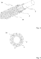
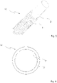
- FIG. 1-4 The embodiments shown in Fig. 1-4 are not according to the invention and are present for illustration purposes only.
- Fig. 1 and Fig. 2 show a superconducting wire 1a not claimed by the invention with a core strand 2 (here: single solid core) surrounded by a multitude of thinner reinforcing strands 3.
- the reinforcing strands 3 form a first cladding, which is in direct contact with the surface of the core strand 2.
- a further cladding (second cladding) is provided surrounding the first cladding and keeping the first cladding in place.
- the second cladding comprises a further strand 4 spirally wound around the first cladding.
- the further strand 4 of the second cladding and the core strand 2 confine an angle ⁇ near to 90°. If smaller angles ⁇ are chosen, more than one further strand is required to form the second cladding.
- the inventive idea is to coat the superconducting core strand 2 with a reinforcement cladding in order to increase the ability of the superconducting wire 1a, 1b, 1c to resist forces acting, e.g., in a magnet.
- thin reinforcement strands 3 are distributed around the circumference of the core strand and are aligned along the core strand 2.
- a second cladding of other thin strands 4, 4' can be provided.
- the superconducting wire 1a, 1b, 1c is even more resistant to radial compression.
- the inventive method allows the reinforcement to be matched/tuned in terms of strength of the reinforcement as well as of type of the reinforcing (longitudinal or radial) by selecting and combining respective materials and by choosing the alignment angle between superconducting strand and reinforcing strands.
Landscapes
- Engineering & Computer Science (AREA)
- Manufacturing & Machinery (AREA)
- Power Engineering (AREA)
- Superconductors And Manufacturing Methods Therefor (AREA)
Claims (9)
- Fil supraconducteur renforcé (1a ; 1b ; 1c) comprenant :un brin de cœur supraconducteur (2) qui présente une surface circonférentielle ;un premier gainage qui comprend un unique brin de renforcement ou une multitude de brins de renforcement (3) ;dans lequel le(s) brin(s) de renforcement (3) est/sont agencé(s) autour de la surface circonférentielle du brin de cœur supraconducteur (2) d'une manière sans croisement, dans lequel le(s) brin(s) de renforcement (3) est/sont en contact avec le brin de cœur supraconducteur (2) et dans lequel il n'y a pas de couche additionnelle entre les brins de renforcement (3) du premier gainage et le brin de cœur supraconducteur (2) ;caractérisé en ce que le(s) brin(s) de renforcement (3) du premier gainage est/sont enroulé(s) en spirale autour de la surface circonférentielle du brin de cœur supraconducteur (2) et en ce que les brins de renforcement (3) sont des brins de renforcement en fibre de carbone.
- Fil supraconducteur renforcé (1a ; 1b ; 1c) selon la revendication 1, caractérisé en ce que les brins de renforcement (3) du premier gainage sont parallèles les uns aux autres.
- Fil supraconducteur renforcé (1a ; 1b ; 1c) selon l'une quelconque des revendications précédentes, caractérisé en ce que le diamètre des brins de renforcement (3) du premier gainage est inférieur au diamètre du brin de cœur supraconducteur (2).
- Fil supraconducteur renforcé (1a ; 1b ; 1c) selon la revendication 3, caractérisé en ce que le diamètre des brins de renforcement (3) du premier gainage est inférieur au diamètre du brin de cœur supraconducteur (2) d'un facteur de 1,1.
- Fil supraconducteur renforcé (1a ; 1b ; 1c) selon l'une quelconque des revendications précédentes, caractérisé en ce que le premier gainage comprend des brins de renforcement de différentes dimensions en coupe transversale.
- Câble supraconducteur comprenant au moins deux fils supraconducteurs renforcés (1a; 1b; 1c) selon l'une quelconque des revendications précédentes.
- Bobine supraconductrice comprenant un câble supraconducteur selon la revendication 6 et/ou un fil supraconducteur renforcé (1a ; 1b ; 1c) selon l'une quelconque des revendications 1 à 5.
- Aimant supraconducteur comprenant une bobine supraconductrice selon la revendication 7.
- Procédé pour produire un fil supraconducteur renforcé (1a; 1b ;1c) selon l'une quelconque des revendications 1 à 5, comprenant les étapes qui suivent :a) la production d'un brin de cœur supraconducteur (2) ; etb) le chemisage du brin de cœur supraconducteur (2) à l'aide d'un premier gainage ;dans lequel un unique brin de renforcement non supraconducteur ou une multitude de brins de renforcement non supraconducteurs (3) est/sont lié(s) au brin de cœur supraconducteur (2) autour de la surface circonférentielle du brin de cœur supraconducteur (2) d'une manière sans croisement, dans lequel les brins de renforcement non supraconducteurs (3) sont en contact avec le brin de cœur supraconducteur (2) et dans lequel aucune couche additionnelle n'est prévue entre les brins de renforcement non supraconducteurs (3) du premier gainage et le brin de cœur supraconducteur (2);caractérisé en ce que le premier gainage est formé en enroulant en spirale les brins de renforcement non supraconducteurs (3) autour de la surface circonférentielle du brin de cœur supraconducteur (2) et les brins de renforcement non supraconducteurs (3) sont des brins de renforcement en fibre de carbone.
Priority Applications (2)
| Application Number | Priority Date | Filing Date | Title |
|---|---|---|---|
| EP19168191.5A EP3723105B1 (fr) | 2019-04-09 | 2019-04-09 | Fil supraconducteur renforcé |
| US16/844,032 US11031155B2 (en) | 2019-04-09 | 2020-04-09 | Reinforced superconducting wire, superconducting cable, superconducting coil and superconducting magnet |
Applications Claiming Priority (1)
| Application Number | Priority Date | Filing Date | Title |
|---|---|---|---|
| EP19168191.5A EP3723105B1 (fr) | 2019-04-09 | 2019-04-09 | Fil supraconducteur renforcé |
Publications (2)
| Publication Number | Publication Date |
|---|---|
| EP3723105A1 EP3723105A1 (fr) | 2020-10-14 |
| EP3723105B1 true EP3723105B1 (fr) | 2022-08-17 |
Family
ID=66286071
Family Applications (1)
| Application Number | Title | Priority Date | Filing Date |
|---|---|---|---|
| EP19168191.5A Active EP3723105B1 (fr) | 2019-04-09 | 2019-04-09 | Fil supraconducteur renforcé |
Country Status (2)
| Country | Link |
|---|---|
| US (1) | US11031155B2 (fr) |
| EP (1) | EP3723105B1 (fr) |
Families Citing this family (1)
| Publication number | Priority date | Publication date | Assignee | Title |
|---|---|---|---|---|
| WO2025196376A1 (fr) * | 2024-03-20 | 2025-09-25 | Nexans | Câble supraconducteur ayant une couche d'absorption d'un effort axial |
Family Cites Families (17)
| Publication number | Priority date | Publication date | Assignee | Title |
|---|---|---|---|---|
| US2111409A (en) | 1936-07-08 | 1938-03-15 | Gen Electric | Electric cable |
| DE1282116B (de) * | 1964-04-17 | 1968-11-07 | Siemens Ag | Supraleitender Draht zum Transport hoher Stroeme |
| FR2122741A5 (fr) * | 1971-01-21 | 1972-09-01 | Comp Generale Electricite | |
| US4646428A (en) * | 1985-11-21 | 1987-03-03 | Oxford Superconducting Technology | Method of fabricating multifilament intermetallic superconductor |
| US5214243A (en) | 1991-10-11 | 1993-05-25 | Endevco Corporation | High-temperature, low-noise coaxial cable assembly with high strength reinforcement braid |
| CA2130072C (fr) | 1994-08-12 | 2003-02-18 | John W. Cherwonogrodzky | Methode de detection d'un agent pathogene au moyen d'un virus |
| US5593524A (en) | 1994-11-14 | 1997-01-14 | Philips; Peter A. | Electrical cable reinforced with a longitudinally applied tape |
| JP3147219B2 (ja) | 1996-01-09 | 2001-03-19 | 矢崎総業株式会社 | 高圧ケーブル |
| JPH10188690A (ja) * | 1996-12-25 | 1998-07-21 | Sumitomo Electric Ind Ltd | 超電導導体の構造 |
| US6534718B1 (en) | 2001-01-30 | 2003-03-18 | Shahin Pourrahimi | Reinforcement of superconducting coils by high-strength materials |
| JP3718480B2 (ja) * | 2002-03-28 | 2005-11-24 | 日本原子力研究所 | 超伝導コイルの交流損失を低減する方法 |
| US20040055780A1 (en) | 2002-07-11 | 2004-03-25 | Susan Hakkarainen | Combined suspension cable and electrical conductor |
| JP4221968B2 (ja) * | 2002-07-31 | 2009-02-12 | 住友電気工業株式会社 | 2芯平行シールドケーブル及び配線部品並びに情報機器 |
| CN1658343A (zh) | 2004-02-16 | 2005-08-24 | 特变电工股份有限公司 | 高温超导线圈的加固装置及加固方法 |
| US9496073B2 (en) | 2013-04-02 | 2016-11-15 | Fermi Research Alliance, Llc | Method and system for controlling chemical reactions between superconductors and metals in superconducting cables |
| CN203787146U (zh) | 2014-03-04 | 2014-08-20 | 鹰潭瑞兴铜业有限公司 | 一种加强型合金铜线 |
| CN108711472B (zh) * | 2018-05-16 | 2020-04-24 | 中国科学院合肥物质科学研究院 | 一种基于rebco超导带材的准圆截面高温超导导体 |
-
2019
- 2019-04-09 EP EP19168191.5A patent/EP3723105B1/fr active Active
-
2020
- 2020-04-09 US US16/844,032 patent/US11031155B2/en active Active
Also Published As
| Publication number | Publication date |
|---|---|
| EP3723105A1 (fr) | 2020-10-14 |
| US20200328013A1 (en) | 2020-10-15 |
| US11031155B2 (en) | 2021-06-08 |
Similar Documents
| Publication | Publication Date | Title |
|---|---|---|
| US5187859A (en) | Method of preloading superconducting coils by using materials with different thermal expansion coefficients | |
| US20140302997A1 (en) | Superconducting Power Cable | |
| CN111613384B (zh) | 一种ReBCO高温超导带材CICC导体及其制造方法 | |
| CN110060815A (zh) | 一种应用于CICC的高温超导ReBCO线缆结构制作方法 | |
| JP5342749B2 (ja) | 高温超電導コイル | |
| US7985925B2 (en) | Superconducting cable and method for the production thereof | |
| JPS6047684B2 (ja) | 超電導複合体およびその製造方法 | |
| US8260386B2 (en) | Armored superconducting winding and method for its production | |
| US9859046B2 (en) | Method and system for controlling chemical reactions between superconductors and metals in superconducting cables | |
| US8173901B2 (en) | Multifilament superconductor, as well as method for its production | |
| US11031155B2 (en) | Reinforced superconducting wire, superconducting cable, superconducting coil and superconducting magnet | |
| US7953466B2 (en) | Superconducting cable | |
| JP5397994B2 (ja) | 超電導ケーブル | |
| WO2018203940A2 (fr) | Câbles supraconducteurs à haute température (hts) et procédé de fabrication | |
| JPH10188692A (ja) | 強制冷却型超電導導体、及びその製造方法、並びに強制冷却型超電導コイルの製造方法 | |
| US11881352B2 (en) | Superconductor with twisted structure | |
| Scanlan et al. | Evaluation of various fabrication techniques for fabrication of fine filament NbTi superconductors | |
| JP2009059652A (ja) | ブロンズ法Nb3Sn超電導線材およびその前駆体 | |
| US20260011489A1 (en) | Improved superconducting magnet reinforcement | |
| JP6345995B2 (ja) | 超電導ケーブルの製造方法 | |
| WO2020067335A1 (fr) | Bobine à oxide supraconducteur et son procédé de production | |
| CN113724941A (zh) | 一种用于提高机械强度的高温超导线材制备方法 | |
| JPH01102812A (ja) | 超電導線 | |
| JPH0452569B2 (fr) | ||
| JPH0950717A (ja) | 交流用超電導導体およびその製造方法ならびにその使用方法 |
Legal Events
| Date | Code | Title | Description |
|---|---|---|---|
| STAA | Information on the status of an ep patent application or granted ep patent |
Free format text: STATUS: EXAMINATION IS IN PROGRESS |
|
| PUAI | Public reference made under article 153(3) epc to a published international application that has entered the european phase |
Free format text: ORIGINAL CODE: 0009012 |
|
| 17P | Request for examination filed |
Effective date: 20200220 |
|
| AK | Designated contracting states |
Kind code of ref document: A1 Designated state(s): AL AT BE BG CH CY CZ DE DK EE ES FI FR GB GR HR HU IE IS IT LI LT LU LV MC MK MT NL NO PL PT RO RS SE SI SK SM TR |
|
| AX | Request for extension of the european patent |
Extension state: BA ME |
|
| GRAP | Despatch of communication of intention to grant a patent |
Free format text: ORIGINAL CODE: EPIDOSNIGR1 |
|
| STAA | Information on the status of an ep patent application or granted ep patent |
Free format text: STATUS: GRANT OF PATENT IS INTENDED |
|
| RIC1 | Information provided on ipc code assigned before grant |
Ipc: H01F 6/06 20060101ALN20220223BHEP Ipc: H01B 7/22 20060101ALN20220223BHEP Ipc: H01B 7/18 20060101ALI20220223BHEP Ipc: H01B 12/02 20060101AFI20220223BHEP |
|
| RIC1 | Information provided on ipc code assigned before grant |
Ipc: H01F 6/06 20060101ALN20220301BHEP Ipc: H01B 7/22 20060101ALN20220301BHEP Ipc: H01B 7/18 20060101ALI20220301BHEP Ipc: H01B 12/02 20060101AFI20220301BHEP |
|
| INTG | Intention to grant announced |
Effective date: 20220323 |
|
| GRAS | Grant fee paid |
Free format text: ORIGINAL CODE: EPIDOSNIGR3 |
|
| GRAA | (expected) grant |
Free format text: ORIGINAL CODE: 0009210 |
|
| STAA | Information on the status of an ep patent application or granted ep patent |
Free format text: STATUS: THE PATENT HAS BEEN GRANTED |
|
| AK | Designated contracting states |
Kind code of ref document: B1 Designated state(s): AL AT BE BG CH CY CZ DE DK EE ES FI FR GB GR HR HU IE IS IT LI LT LU LV MC MK MT NL NO PL PT RO RS SE SI SK SM TR |
|
| REG | Reference to a national code |
Ref country code: CH Ref legal event code: EP |
|
| REG | Reference to a national code |
Ref country code: DE Ref legal event code: R096 Ref document number: 602019018282 Country of ref document: DE |
|
| REG | Reference to a national code |
Ref country code: IE Ref legal event code: FG4D |
|
| REG | Reference to a national code |
Ref country code: AT Ref legal event code: REF Ref document number: 1512704 Country of ref document: AT Kind code of ref document: T Effective date: 20220915 |
|
| REG | Reference to a national code |
Ref country code: NL Ref legal event code: MP Effective date: 20220817 |
|
| REG | Reference to a national code |
Ref country code: LT Ref legal event code: MG9D |
|
| PG25 | Lapsed in a contracting state [announced via postgrant information from national office to epo] |
Ref country code: SE Free format text: LAPSE BECAUSE OF FAILURE TO SUBMIT A TRANSLATION OF THE DESCRIPTION OR TO PAY THE FEE WITHIN THE PRESCRIBED TIME-LIMIT Effective date: 20220817 Ref country code: RS Free format text: LAPSE BECAUSE OF FAILURE TO SUBMIT A TRANSLATION OF THE DESCRIPTION OR TO PAY THE FEE WITHIN THE PRESCRIBED TIME-LIMIT Effective date: 20220817 Ref country code: PT Free format text: LAPSE BECAUSE OF FAILURE TO SUBMIT A TRANSLATION OF THE DESCRIPTION OR TO PAY THE FEE WITHIN THE PRESCRIBED TIME-LIMIT Effective date: 20221219 Ref country code: NO Free format text: LAPSE BECAUSE OF FAILURE TO SUBMIT A TRANSLATION OF THE DESCRIPTION OR TO PAY THE FEE WITHIN THE PRESCRIBED TIME-LIMIT Effective date: 20221117 Ref country code: NL Free format text: LAPSE BECAUSE OF FAILURE TO SUBMIT A TRANSLATION OF THE DESCRIPTION OR TO PAY THE FEE WITHIN THE PRESCRIBED TIME-LIMIT Effective date: 20220817 Ref country code: LV Free format text: LAPSE BECAUSE OF FAILURE TO SUBMIT A TRANSLATION OF THE DESCRIPTION OR TO PAY THE FEE WITHIN THE PRESCRIBED TIME-LIMIT Effective date: 20220817 Ref country code: LT Free format text: LAPSE BECAUSE OF FAILURE TO SUBMIT A TRANSLATION OF THE DESCRIPTION OR TO PAY THE FEE WITHIN THE PRESCRIBED TIME-LIMIT Effective date: 20220817 Ref country code: FI Free format text: LAPSE BECAUSE OF FAILURE TO SUBMIT A TRANSLATION OF THE DESCRIPTION OR TO PAY THE FEE WITHIN THE PRESCRIBED TIME-LIMIT Effective date: 20220817 |
|
| REG | Reference to a national code |
Ref country code: AT Ref legal event code: MK05 Ref document number: 1512704 Country of ref document: AT Kind code of ref document: T Effective date: 20220817 |
|
| PG25 | Lapsed in a contracting state [announced via postgrant information from national office to epo] |
Ref country code: PL Free format text: LAPSE BECAUSE OF FAILURE TO SUBMIT A TRANSLATION OF THE DESCRIPTION OR TO PAY THE FEE WITHIN THE PRESCRIBED TIME-LIMIT Effective date: 20220817 Ref country code: IS Free format text: LAPSE BECAUSE OF FAILURE TO SUBMIT A TRANSLATION OF THE DESCRIPTION OR TO PAY THE FEE WITHIN THE PRESCRIBED TIME-LIMIT Effective date: 20221217 Ref country code: HR Free format text: LAPSE BECAUSE OF FAILURE TO SUBMIT A TRANSLATION OF THE DESCRIPTION OR TO PAY THE FEE WITHIN THE PRESCRIBED TIME-LIMIT Effective date: 20220817 Ref country code: GR Free format text: LAPSE BECAUSE OF FAILURE TO SUBMIT A TRANSLATION OF THE DESCRIPTION OR TO PAY THE FEE WITHIN THE PRESCRIBED TIME-LIMIT Effective date: 20221118 |
|
| PG25 | Lapsed in a contracting state [announced via postgrant information from national office to epo] |
Ref country code: SM Free format text: LAPSE BECAUSE OF FAILURE TO SUBMIT A TRANSLATION OF THE DESCRIPTION OR TO PAY THE FEE WITHIN THE PRESCRIBED TIME-LIMIT Effective date: 20220817 Ref country code: RO Free format text: LAPSE BECAUSE OF FAILURE TO SUBMIT A TRANSLATION OF THE DESCRIPTION OR TO PAY THE FEE WITHIN THE PRESCRIBED TIME-LIMIT Effective date: 20220817 Ref country code: ES Free format text: LAPSE BECAUSE OF FAILURE TO SUBMIT A TRANSLATION OF THE DESCRIPTION OR TO PAY THE FEE WITHIN THE PRESCRIBED TIME-LIMIT Effective date: 20220817 Ref country code: DK Free format text: LAPSE BECAUSE OF FAILURE TO SUBMIT A TRANSLATION OF THE DESCRIPTION OR TO PAY THE FEE WITHIN THE PRESCRIBED TIME-LIMIT Effective date: 20220817 Ref country code: CZ Free format text: LAPSE BECAUSE OF FAILURE TO SUBMIT A TRANSLATION OF THE DESCRIPTION OR TO PAY THE FEE WITHIN THE PRESCRIBED TIME-LIMIT Effective date: 20220817 Ref country code: AT Free format text: LAPSE BECAUSE OF FAILURE TO SUBMIT A TRANSLATION OF THE DESCRIPTION OR TO PAY THE FEE WITHIN THE PRESCRIBED TIME-LIMIT Effective date: 20220817 |
|
| REG | Reference to a national code |
Ref country code: DE Ref legal event code: R097 Ref document number: 602019018282 Country of ref document: DE |
|
| PG25 | Lapsed in a contracting state [announced via postgrant information from national office to epo] |
Ref country code: SK Free format text: LAPSE BECAUSE OF FAILURE TO SUBMIT A TRANSLATION OF THE DESCRIPTION OR TO PAY THE FEE WITHIN THE PRESCRIBED TIME-LIMIT Effective date: 20220817 Ref country code: EE Free format text: LAPSE BECAUSE OF FAILURE TO SUBMIT A TRANSLATION OF THE DESCRIPTION OR TO PAY THE FEE WITHIN THE PRESCRIBED TIME-LIMIT Effective date: 20220817 |
|
| PLBE | No opposition filed within time limit |
Free format text: ORIGINAL CODE: 0009261 |
|
| STAA | Information on the status of an ep patent application or granted ep patent |
Free format text: STATUS: NO OPPOSITION FILED WITHIN TIME LIMIT |
|
| PG25 | Lapsed in a contracting state [announced via postgrant information from national office to epo] |
Ref country code: AL Free format text: LAPSE BECAUSE OF FAILURE TO SUBMIT A TRANSLATION OF THE DESCRIPTION OR TO PAY THE FEE WITHIN THE PRESCRIBED TIME-LIMIT Effective date: 20220817 |
|
| 26N | No opposition filed |
Effective date: 20230519 |
|
| PG25 | Lapsed in a contracting state [announced via postgrant information from national office to epo] |
Ref country code: SI Free format text: LAPSE BECAUSE OF FAILURE TO SUBMIT A TRANSLATION OF THE DESCRIPTION OR TO PAY THE FEE WITHIN THE PRESCRIBED TIME-LIMIT Effective date: 20220817 |
|
| PG25 | Lapsed in a contracting state [announced via postgrant information from national office to epo] |
Ref country code: LU Free format text: LAPSE BECAUSE OF NON-PAYMENT OF DUE FEES Effective date: 20230409 |
|
| REG | Reference to a national code |
Ref country code: BE Ref legal event code: MM Effective date: 20230430 |
|
| PG25 | Lapsed in a contracting state [announced via postgrant information from national office to epo] |
Ref country code: MC Free format text: LAPSE BECAUSE OF FAILURE TO SUBMIT A TRANSLATION OF THE DESCRIPTION OR TO PAY THE FEE WITHIN THE PRESCRIBED TIME-LIMIT Effective date: 20220817 |
|
| P01 | Opt-out of the competence of the unified patent court (upc) registered |
Effective date: 20231221 |
|
| PG25 | Lapsed in a contracting state [announced via postgrant information from national office to epo] |
Ref country code: MC Free format text: LAPSE BECAUSE OF FAILURE TO SUBMIT A TRANSLATION OF THE DESCRIPTION OR TO PAY THE FEE WITHIN THE PRESCRIBED TIME-LIMIT Effective date: 20220817 |
|
| REG | Reference to a national code |
Ref country code: IE Ref legal event code: MM4A |
|
| PG25 | Lapsed in a contracting state [announced via postgrant information from national office to epo] |
Ref country code: BE Free format text: LAPSE BECAUSE OF NON-PAYMENT OF DUE FEES Effective date: 20230430 |
|
| PG25 | Lapsed in a contracting state [announced via postgrant information from national office to epo] |
Ref country code: IE Free format text: LAPSE BECAUSE OF NON-PAYMENT OF DUE FEES Effective date: 20230409 |
|
| PG25 | Lapsed in a contracting state [announced via postgrant information from national office to epo] |
Ref country code: IE Free format text: LAPSE BECAUSE OF NON-PAYMENT OF DUE FEES Effective date: 20230409 |
|
| PG25 | Lapsed in a contracting state [announced via postgrant information from national office to epo] |
Ref country code: IT Free format text: LAPSE BECAUSE OF FAILURE TO SUBMIT A TRANSLATION OF THE DESCRIPTION OR TO PAY THE FEE WITHIN THE PRESCRIBED TIME-LIMIT Effective date: 20220817 |
|
| PG25 | Lapsed in a contracting state [announced via postgrant information from national office to epo] |
Ref country code: BG Free format text: LAPSE BECAUSE OF FAILURE TO SUBMIT A TRANSLATION OF THE DESCRIPTION OR TO PAY THE FEE WITHIN THE PRESCRIBED TIME-LIMIT Effective date: 20220817 |
|
| PG25 | Lapsed in a contracting state [announced via postgrant information from national office to epo] |
Ref country code: BG Free format text: LAPSE BECAUSE OF FAILURE TO SUBMIT A TRANSLATION OF THE DESCRIPTION OR TO PAY THE FEE WITHIN THE PRESCRIBED TIME-LIMIT Effective date: 20220817 |
|
| PGFP | Annual fee paid to national office [announced via postgrant information from national office to epo] |
Ref country code: DE Payment date: 20250417 Year of fee payment: 7 |
|
| PGFP | Annual fee paid to national office [announced via postgrant information from national office to epo] |
Ref country code: FR Payment date: 20250422 Year of fee payment: 7 |
|
| PGFP | Annual fee paid to national office [announced via postgrant information from national office to epo] |
Ref country code: CH Payment date: 20250501 Year of fee payment: 7 |
|
| PG25 | Lapsed in a contracting state [announced via postgrant information from national office to epo] |
Ref country code: CY Free format text: LAPSE BECAUSE OF FAILURE TO SUBMIT A TRANSLATION OF THE DESCRIPTION OR TO PAY THE FEE WITHIN THE PRESCRIBED TIME-LIMIT; INVALID AB INITIO Effective date: 20190409 |
|
| PG25 | Lapsed in a contracting state [announced via postgrant information from national office to epo] |
Ref country code: HU Free format text: LAPSE BECAUSE OF FAILURE TO SUBMIT A TRANSLATION OF THE DESCRIPTION OR TO PAY THE FEE WITHIN THE PRESCRIBED TIME-LIMIT; INVALID AB INITIO Effective date: 20190409 |
|
| PG25 | Lapsed in a contracting state [announced via postgrant information from national office to epo] |
Ref country code: TR Free format text: LAPSE BECAUSE OF FAILURE TO SUBMIT A TRANSLATION OF THE DESCRIPTION OR TO PAY THE FEE WITHIN THE PRESCRIBED TIME-LIMIT Effective date: 20220817 |
|
| PGFP | Annual fee paid to national office [announced via postgrant information from national office to epo] |
Ref country code: GB Payment date: 20260324 Year of fee payment: 8 |
|
| REG | Reference to a national code |
Ref country code: CH Ref legal event code: U11 Free format text: ST27 STATUS EVENT CODE: U-0-0-U10-U11 (AS PROVIDED BY THE NATIONAL OFFICE) Effective date: 20260501 |