EP3724523B1 - Befestigungsvorrichtung, befestigungsanordnung mit einer solchen vorrichtung und verfahren zur herstellung einer solchen anordnung - Google Patents
Befestigungsvorrichtung, befestigungsanordnung mit einer solchen vorrichtung und verfahren zur herstellung einer solchen anordnung Download PDFInfo
- Publication number
- EP3724523B1 EP3724523B1 EP18833919.6A EP18833919A EP3724523B1 EP 3724523 B1 EP3724523 B1 EP 3724523B1 EP 18833919 A EP18833919 A EP 18833919A EP 3724523 B1 EP3724523 B1 EP 3724523B1
- Authority
- EP
- European Patent Office
- Prior art keywords
- section
- support
- longitudinal axis
- angle
- assembly
- Prior art date
- Legal status (The legal status is an assumption and is not a legal conclusion. Google has not performed a legal analysis and makes no representation as to the accuracy of the status listed.)
- Active
Links
Images


Classifications
-
- F—MECHANICAL ENGINEERING; LIGHTING; HEATING; WEAPONS; BLASTING
- F16—ENGINEERING ELEMENTS AND UNITS; GENERAL MEASURES FOR PRODUCING AND MAINTAINING EFFECTIVE FUNCTIONING OF MACHINES OR INSTALLATIONS; THERMAL INSULATION IN GENERAL
- F16B—DEVICES FOR FASTENING OR SECURING CONSTRUCTIONAL ELEMENTS OR MACHINE PARTS TOGETHER, e.g. NAILS, BOLTS, CIRCLIPS, CLAMPS, CLIPS OR WEDGES; JOINTS OR JOINTING
- F16B37/00—Nuts or like thread-engaging members
- F16B37/04—Devices for fastening nuts to surfaces, e.g. sheets, plates
- F16B37/06—Devices for fastening nuts to surfaces, e.g. sheets, plates by means of welding or riveting
- F16B37/062—Devices for fastening nuts to surfaces, e.g. sheets, plates by means of welding or riveting by means of riveting
- F16B37/065—Devices for fastening nuts to surfaces, e.g. sheets, plates by means of welding or riveting by means of riveting by deforming the material of the nut
- F16B37/067—Devices for fastening nuts to surfaces, e.g. sheets, plates by means of welding or riveting by means of riveting by deforming the material of the nut the material of the nut being deformed by a threaded member generating axial movement of the threaded part of the nut, e.g. blind rivet type
-
- F—MECHANICAL ENGINEERING; LIGHTING; HEATING; WEAPONS; BLASTING
- F16—ENGINEERING ELEMENTS AND UNITS; GENERAL MEASURES FOR PRODUCING AND MAINTAINING EFFECTIVE FUNCTIONING OF MACHINES OR INSTALLATIONS; THERMAL INSULATION IN GENERAL
- F16B—DEVICES FOR FASTENING OR SECURING CONSTRUCTIONAL ELEMENTS OR MACHINE PARTS TOGETHER, e.g. NAILS, BOLTS, CIRCLIPS, CLAMPS, CLIPS OR WEDGES; JOINTS OR JOINTING
- F16B19/00—Bolts without screw-thread; Pins, including deformable elements; Rivets
- F16B19/04—Rivets; Spigots or the like fastened by riveting
- F16B19/06—Solid rivets made in one piece
-
- F—MECHANICAL ENGINEERING; LIGHTING; HEATING; WEAPONS; BLASTING
- F16—ENGINEERING ELEMENTS AND UNITS; GENERAL MEASURES FOR PRODUCING AND MAINTAINING EFFECTIVE FUNCTIONING OF MACHINES OR INSTALLATIONS; THERMAL INSULATION IN GENERAL
- F16B—DEVICES FOR FASTENING OR SECURING CONSTRUCTIONAL ELEMENTS OR MACHINE PARTS TOGETHER, e.g. NAILS, BOLTS, CIRCLIPS, CLAMPS, CLIPS OR WEDGES; JOINTS OR JOINTING
- F16B19/00—Bolts without screw-thread; Pins, including deformable elements; Rivets
- F16B19/04—Rivets; Spigots or the like fastened by riveting
- F16B19/08—Hollow rivets; Multi-part rivets
- F16B19/086—Self-piercing rivets
Definitions
- the invention relates to fixing devices, and more particularly to fixing devices suitable for supports made of composite material.
- composite material a material comprising a matrix made from a thermoplastic material, such as polyolefins, polyamides or polypropylenes, or from a thermosetting material, such as unsaturated polyesters, polyepoxides or polyurethanes.
- a composite material can comprise reinforcements made from a material distinct from the matrix, for example glass, carbon, aramid or other fibres, taken alone or in combination.
- a part is fixed on a support using an insert previously fixed on the support.
- An insert can be a nut, a rivet, a screw or a stud, or even an insert having a spacer function or a ball joint function.
- a nut is a threaded hollow element, that is to say which has an internal thread, intended to be fixed to a threaded part.
- a rivet is an assembly element of flat parts.
- a screw or stud is a threaded element, that is to say which has an external thread capable of receiving the internal thread of a part to be fixed to the support.
- An insert with a spacer function makes it possible to maintain a constant distance between the part and the support.
- An insert with a ball joint function comprises a spherical head in order, in particular, to provide a ball joint connection.
- inserts intended to be fixed on supports made of composite material must be suitable for resisting tensile and shearing forces in order to guarantee a good resistance of the mechanical connection between the support on which they are fixed and the part which one wishes to fix to the insert, that is to say to the support.
- inserts whose body is embedded in a thermoplastic or thermosetting resin.
- Some inserts comprise a body extending along a longitudinal axis, such as a barrel, and a base welded or crimped to one end of the body.
- the base has the shape of a circular or parallelepipedal plate.
- the base is also perforated, that is to say that several through circular orifices are formed in the base.
- the circular orifices are intended to allow reinforcement fibers and resin to penetrate so as to create gripping and reinforcement zones.
- These inserts have their base integrated into the support.
- the support is molded by injecting a resin on the insert so as to embed the base in the resin to mechanically fix the insert to the support when the resin hardens.
- resin is a fluid material that can harden under the effect of heat and which is made from polyester and glass fibers.
- these inserts require prior preparation for the assembly of the body and the base.
- the insert is made from a material other than resin, for example steel, good mechanical strength between the insert and the support is difficult to obtain. Indeed, the penetration of the resin into the circular orifices is random, and in this case the reinforcing fibers are not distributed sufficiently around the base. The insert is then poorly anchored within the molded support.
- a plate consisting of a composite material with fibrous reinforcements in a matrix consisting of a thermoplastic polymer, and a metal part comprising a mechanical interface to perform technical functions of the joint, such as a pivot connection or indexing angular.
- the metal part further comprises a plate comprising a plurality of cylindrical pins substantially perpendicular to the plate and which penetrate into the plate to bind the metal part to the plate.
- flanged holes can be made in the plate, and form coupling patterns which penetrate into the plate.
- the document EP2947336 discloses a blind nut with an internal thread.
- the blind nut includes a hollow tubular portion adjacent to the internal thread and a flange.
- a portion of the tubular part can be plastically deformed so as to increase its diameter, and fix the nut to a fastener.
- the part with the internal thread comprises a first straight part adjacent to the tubular part, a first conical portion whose external diameter gradually decreases from the first straight part as well as a second straight part whose external diameter is smaller than the first straight part, a second conical part with a progressive outer diameter decreasing from the first straight part, and a third straight part with a smaller outer diameter than the second straight part.
- the document FROM 10 2014 206787 discloses a semi-tubular punch rivet for joining parts without pre-drilling.
- the rivet includes a rivet head and an adjacent rivet shank.
- the rivet shank defines a concentric recess and a rivet base with a punched edge.
- the rivet foot has a larger outside diameter than the rest of the rivet shank.
- the document JP H10 61628 discloses an element having a hemispherical or trapezoidal head surmounted by a stem and terminated by a point.
- the tip has two portions each having a different angle with respect to the longitudinal axis.
- the tip is defined by a frustoconical portion and a conical portion.
- the document FR 2 734 143 discloses a pyrotechnic nailing box with a fixing nail having a conical tip followed by a frustoconical portion and a circular section
- An object of the invention consists in overcoming these drawbacks, and more particularly in providing a means for fixing an insert to a support made of composite material while guaranteeing good mechanical strength between the insert and the support, and more particularly a means for fixing the insert by drilling the support.
- a fixation device comprising a shaft extending along a longitudinal axis and a distal end comprising a first section adjacent to the shaft and having an inclined outer surface at a first angle relative to the longitudinal axis.
- the distal end comprises a second section adjacent to the first section and having an outer surface inclined at a second angle relative to the longitudinal axis, the respective outer surfaces of the first and second sections flaring out in the same direction and the first and second angles having different respective values.
- a fixing device is provided, one end of which is particularly suitable for fixing the fixing device to a support made of composite material by drilling the support.
- the end forms a convex or concave point which facilitates the drilling of the support.
- Such a fixing device can be used by piercing the support by a translation of the device and by exerting a sufficient pressure force. The need to rotate the device to perform the drilling is avoided.
- the first and second sections may have a tapered outer surface.
- the frustoconical outer surfaces of the first and second sections can widen in the direction of the barrel and the second angle is strictly greater than the first angle.
- the device comprises a proximal end opposite the distal end, the tapered outer surfaces of the first and second sections being able to widen in a direction opposite to the proximal end and the second angle being strictly less than the first angle.
- the barrel has an undercut section, wherein grooves extending along the longitudinal axis are formed on an outer surface of the undercut section.
- the grooves facilitate the insertion of the fixing device within a support made of composite material.
- the barrel is hollow and the release section has a thread located on an interior surface of the release section.
- the device may comprise a support head adjacent to the barrel and located opposite the distal end, the barrel comprising a crimping section extending between the support head and the release section and being deformable to forming a crimping bead, a separation section extending between the bearing head and the crimping section, and a shoulder formed between the separation section and the crimping section.
- the bearing head can extend radially with respect to the longitudinal axis and has a projecting length of the separation section that is less than a length of the separation section extending along the longitudinal axis.
- the device may be hollow in which a through hole is formed within the distal end.
- a fixing assembly comprising a support and a fixing device, as defined above, mounted on the support.
- a method of manufacturing a fastening assembly comprising a hole in the support of the assembly by introducing the fastening device of the assembly into the support.
- the bore may include heating of the support of the assembly.
- a fixing device 1, or insert comprising a shaft 2 and a distal end 3.
- the device 1 is intended to be mounted on a support 4 made of composite material, as illustrated in the figures 6 to 10 .
- the device 1 is particularly suitable for being introduced into such a support 4 by piercing the support 4.
- the shaft 2 extends along a longitudinal axis A.
- the distal end 3 is located at a termination of the barrel 2.
- the distal end 3 comprises a first section 5 adjacent to the barrel 2 and having an outer surface inclined at a first angle 6 with respect to the longitudinal axis A.
- the first angle 6 corresponds to the angular sector located between the outer surface of the first section 5 and the longitudinal axis A and which is visible from the outside of the fixing device 1. More precisely, the first angle 6 corresponds to the complementary angle adjacent to the angle between a straight line normal to the outer surface of the first section 5 and the longitudinal axis A.
- the distal end 3 comprises a second section 7 adjacent to the first section 5 and having an outer surface inclined at a second angle 8 with respect to the longitudinal axis A.
- the second angle 8 corresponds to the angular sector located between the outer surface of the second section 7 and the longitudinal axis A and which is visible from the outside of the fixing device 1.
- the second angle 8 corresponds to the complementary angle adjacent to the angle between a straight line normal to the outer surface of the second section 7 and the longitudinal axis A. More particularly, the respective outer surfaces of the first and second sections 5, 7 flare out in the same direction. The direction may correspond to the orientation of the barrel 2 towards the distal end 3, as illustrated in the figures 3, 3b and 4 , or the opposite orientation, as shown in the figures 1, 2 And 5 to 10 . Furthermore, the first and second angles 6, 8 have different respective values. Thus, a distal end 3 is obtained having two sections 5, 7 inclined differently to facilitate the drilling of a support 4 made of composite material by the device 1. For example, the first and second sections 5, 7 each have a frustoconical external surface , which facilitates the manufacture of the device 1. In addition, the shaft 2 has a proximal end 9 located opposite the distal end 3.
- the outer surfaces of the first and second sections 5, 7 are respectively frustoconical and widen in the direction of the shaft 2.
- the second angle 8 has a value strictly greater than that of the first angle 6.
- the first and second angles 6, 8 are acute.
- the first angle ⁇ has a value comprised between 30° and 45° and the second angle ⁇ has a value comprised between 50° and 55°.
- the inclination of the second section 7 makes it possible to bear on the support 4 without cutting the reinforcing fibers.
- the first section 5 makes it possible to separate the reinforcing fibers during the drilling of the support 4 by the device 1.
- the outer surfaces of the first and second sections 5, 7 are respectively tapered and flare in a direction opposite to the proximal end 9. Furthermore, the second angle 8 has a value strictly lower than that of the first angle 6. According to this second embodiment, the first and second angles 6, 8 are obtuse.
- the first angle ⁇ has a value comprised between 135° and 150° and the second angle ⁇ has a value comprised between 125° and 130°.
- the outer surfaces of the first and second sections 5, 7 are respectively frustoconical and conical and widen in a direction opposite to the proximal end 9.
- the first and second angles 6, 8 are obtuse.
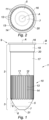
- the barrel 2 may further comprise a clearance section 10.
- Grooves 11 extending along the longitudinal axis A are formed on an outer surface of the clearance section 10.
- the grooves 11 correspond to long notches open towards the outside of the device 1, that is to say that a bottom of a groove 11 is visible from the outside of the device 1.
- the grooves 11 have a section that is partly rectangular, or in the shape of a dovetail , or partly parallelepipedic, or partly spherical. In particular, the grooves 11 open out at the junction between the release section 10 and the distal end 3.
- External parts 12 of the outer surface of the release section 10 each located between two grooves 11 have a shape parallelepipedal.
- the outer portions 12 may be strip-like.
- the outer parts 12 have two edges 13, 14 extending along the longitudinal axis A.
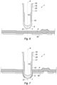
- the grooves 11 promote the flow of the reinforcing fibers separated from the material of the support 4 during the introduction of the device 1 within of support 4, as shown in figure 7 .
- the grooves 11 also make it possible to increase the outer surface of the release section 10 in contact with the material of the support 4.
- the grooves 11 facilitate the introduction of the device 1 by limiting a discharge of material towards the front of the device 1, that is to say towards the distal end 3 of the device 1.
- the material of the support 4 located in front of the device 1 is pushed back radially by the distal end 3.
- the pushed back material is evacuated by the grooves 11 along the release section 10.
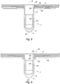
- the device 1 can also comprise a support head 16 adjacent to the barrel 2 and located at the level of the proximal end 9, that is to say located opposite the distal end 3
- the bearing head 16 extends radially with respect to the longitudinal axis A.
- the bearing head 16 extends along a transverse axis B perpendicular to the axis longitudinal a.
- the barrel 2 comprises a crimping section 17, deformable to form a crimping bead 18, during a crimping operation of the fastening device 1 on the support 4, as illustrated in figure 9 .
- the crimping section 17 extends between the support head 16 and the release section 10.
- the barrel 2 may include a separation section 19 extending between the support head 16 and the crimping section 17.
- the barrel 2 may include a shoulder 20 formed between the separation section 19 and the crimping section 17.
- the thickness of the separation section 19 is greater than that of the crimping section 17.
- the height of the separation section 19 is adapted to the thickness of the support 4, so that, when crimping the device 1, the support 4 is wedged between the support head 16 and the crimping bead 18, as illustrated in there figure 9 .
- the bearing head 16 forms a collar projecting from an outer surface of the separation section 19.
- the bearing head 16 has a projecting length of the separation section 19 less than a length of the separation section 19 s 'extending along the longitudinal axis A.
- the barrel 2 includes an anti-rotation section 30 extending between the first section 5 and the release section 10.
- the device 1 comprises an end section 31 located at its proximal end 9.
- the end section 31 extends from the support head 16 in the direction opposite to the release section 10.
- the end section 31 may include an external thread 32 and the device 1 is a screw or a stud.
- the barrel 2 is hollow.
- the release section 10 has an internal thread 15, as shown in the figures 6 to 9 , the device is then a nut.
- the internal thread 15 extends over part of an inner surface of the release section 10.
- the internal thread 15 extends only over the inner surface of the release section 10.
- the barrel 2 is hollow and the device 1 is blind, that is to say the second section 7 is closed.
- the second section 7 comprises an end surface 21 extending radially with respect to the longitudinal axis A, to close the second section 7.
- a straight line normal to the end surface 21 is parallel to the longitudinal axis A.
- the end surface 21 is flat, and in this case, it makes it possible to limit the ruptures of the reinforcing fibers of the support, compared to a conventional pointed end. In addition, it protects the users who manipulate the device 1, and prevents them from injuring themselves.
- the device 1 the shaft 2 is hollow and the device 1 is blind.
- the outer surfaces of the first and second sections 5, 7 flare in a direction opposite to the proximal end 9.
- the first section 5 is frustoconical and the second section 7 is conical, the apex of which is denoted by the reference 23
- the distal end 3 is pointed and located inside the shaft 2. The tip of the distal end 3 cannot injure a user who manipulates the device 1.
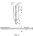
- the device 1 is hollow and a through hole 22 can be formed within the distal end 3.
- the through hole 22 is shaped to receive a pin 40 to pierce the support 4.
- the device 1 can be made in a single one-piece piece.
- the device 1 can be metallic or made of thermoplastic material.
- the fastening assembly 41 comprises the support 4 and the fastening device 1 mounted on the support 4.
- the fastening assembly 41 is intended to receive a part fixed to the device 1.
- the device 1 is placed opposite a first side of the support 4, ready to be introduced into the support 4.
- the support 4 may comprise a reinforcing plate 42 located on a second side opposite the first side.
- the support 4 is pierced with the device 1.
- a mold is used to control the pressure exerted on the support 4.
- the material of the support 4 is separated by the distal end 3 of the device 1, then the discarded material is evacuated by the grooves 11 of the clearance section 10.
- the device 1 is introduced into the support 4, until the support head 16 of the device 1 is in contact with the first side of the support 4, as shown on the figure 8 .
- the method can comprise heating the support 4 during the introduction of the fixing device 1 within the support 4, in order to facilitate the penetration of the device 1. Then, when the device 1 comprises a crimping section 17, the device 1 is crimped to the support 4, by deforming the crimping section 17 so as to create the crimping bead 18 and to wedge the support 4 between the bearing head 16 and the bead 18, as illustrated in the figure 9 .
- the crimping of the device 1 makes it possible to effectively fix the device 1 to the support 4, by increasing the resistance of the device 1 to tearing.
- FIG 10 another mode of implementation of the method of manufacturing the fixing assembly 41 has been shown.
- a pin 40 whether rotating or not, passes through the through-orifice 22 of the device 1.
- the pin 40 initiates the drilling of the support 4, and the distal end 3 of the device 1 comes into contact with the material of the support 4 separated by the pin 40.
- the end 3 participates in the drilling and also moves the material of the support 4.
- the fixing device which has just been described makes it possible to improve the mechanical strength of an insert with a support made of composite material.
- the insert is particularly suitable in the automotive, aeronautical and aerospace fields.
Landscapes
- Engineering & Computer Science (AREA)
- General Engineering & Computer Science (AREA)
- Mechanical Engineering (AREA)
- Connection Of Plates (AREA)
- Insertion Pins And Rivets (AREA)
- Joining Of Building Structures In Genera (AREA)
Claims (10)
- Befestigungsvorrichtung, umfassend einen Schaft (2), der sich entlang einer Längsachse (A) erstreckt, und ein distales Ende (3), das einen ersten Abschnitt (5) aufweist, der am Schaft (2) angrenzt und eine Außenfläche hat, die relativ zur Längsachse (A) in einem ersten Winkel (6) geneigt ist, wobei das distale Ende (3) einen zweiten Abschnitt (7) aufweist, der am ersten Abschnitt (5) angrenzt und eine Außenfläche hat, die relativ zur Längsachse (A) in einem zweiten Winkel (8) geneigt ist, wobei die jeweiligen Außenflächen des ersten und des zweiten Abschnitts (5, 7) sich in eine gleiche Richtung aufweiten und der erste und der zweite Winkel (6, 8) jeweils unterschiedliche Werte haben, dadurch gekennzeichnet, dass der Schaft (2) einen Räumabschnitt (10) umfasst, wobei auf einer Außenfläche des Räumabschnitts (10) Nuten (11) ausgebildet sind, die sich entlang der Längsachse (A) erstrecken, und dadurch, dass der Schaft (2) hohl ist und der Räumabschnitt (10) ein Gewinde (15) aufweist, das auf einer Innenfläche des Räumabschnitts (10) angeordnet ist
- Befestigungsvorrichtung nach Anspruch 1, wobei der erste und der zweite Abschnitt (5, 7) eine kegelstumpfförmige Außenfläche haben.
- Befestigungsvorrichtung nach Anspruch 2, wobei die kegelstumpfförmigen Außenflächen des ersten und des zweiten Abschnitts (5, 7) sich in Richtung des Schafts (2) aufweiten und der zweite Winkel (8) größer als der erste Winkel (6) ist.
- Befestigungsvorrichtung nach Anspruch 2, umfassend ein proximales Ende (9), das dem distalen Ende (3) entgegengesetzt ist, wobei die kegelstumpfförmigen Außenflächen des ersten und des zweiten Abschnitts (5, 7) sich in einer dem proximalen Ende (9) entgegengesetzten Richtung aufweiten und der zweite Winkel (8) kleiner als der erste Winkel (6) ist.
- Befestigungsvorrichtung nach einem der Ansprüche 1 bis 4, umfassend einen Stützkopf (16), der am Schaft (2) angrenzt und dem distalen Ende (3) gegenüberliegend angeordnet ist, wobei der Schaft (2) umfasst: einen Crimpabschnitt (17), der sich zwischen dem Stützkopf (16) und dem Räumabschnitt (10) erstreckt und verformbar ist, um einen Crimp-Wulst (18) zu bilden, einen Trennabschnitt (19), der sich zwischen dem Stützkopf (16) und dem Crimpabschnitt (17) erstreckt, und eine Schulter (20), die zwischen dem Trennabschnitt (19) und dem Crimpabschnitt (17) ausgebildet ist.
- Befestigungsvorrichtung nach Anspruch 5, wobei der Stützkopf (16) sich radial zur Längsachse (A) erstreckt und eine vom Trennabschnitt (19) vorspringende Länge hat, die kleiner als eine sich entlang der Längsachse (A) erstreckende Länge des Trennabschnitts (19) ist.
- Befestigungsvorrichtung nach einem der Ansprüche 1 bis 6, in welchem innerhalb des distalen Endes (3) eine Durchgangsöffnung (22) ausgebildet ist.
- Befestigungsanordnung, umfassend einen Träger (4) und eine auf dem Träger (4) montierte Befestigungsvorrichtung (1) nach einem der Ansprüche 1 bis 7.
- Verfahren zur Herstellung einer Befestigungsanordnung nach Anspruch 8, umfassend ein Durchbohren des Trägers (4) der Anordnung durch Einführen der Befestigungsvorrichtung (1) der Anordnung in das Innere des Trägers (4).
- Verfahren nach Anspruch 9, wobei das Durchbohren ein Erhitzen des Trägers (4) der Anordnung umfasst.
Applications Claiming Priority (2)
| Application Number | Priority Date | Filing Date | Title |
|---|---|---|---|
| FR1761932A FR3076326B1 (fr) | 2017-12-11 | 2017-12-11 | Dispositif de fixation, ensemble de fixation comprenant un tel dispositif et procede de fabrication d’un tel ensemble |
| PCT/FR2018/053210 WO2019115935A1 (fr) | 2017-12-11 | 2018-12-11 | Dispositif de fixation, ensemble de fixation comprenant un tel dispositif et procede de fabrication d'un tel ensemble |
Publications (2)
| Publication Number | Publication Date |
|---|---|
| EP3724523A1 EP3724523A1 (de) | 2020-10-21 |
| EP3724523B1 true EP3724523B1 (de) | 2023-06-21 |
Family
ID=61132693
Family Applications (1)
| Application Number | Title | Priority Date | Filing Date |
|---|---|---|---|
| EP18833919.6A Active EP3724523B1 (de) | 2017-12-11 | 2018-12-11 | Befestigungsvorrichtung, befestigungsanordnung mit einer solchen vorrichtung und verfahren zur herstellung einer solchen anordnung |
Country Status (3)
| Country | Link |
|---|---|
| EP (1) | EP3724523B1 (de) |
| FR (1) | FR3076326B1 (de) |
| WO (1) | WO2019115935A1 (de) |
Family Cites Families (5)
| Publication number | Priority date | Publication date | Assignee | Title |
|---|---|---|---|---|
| FR2374143A1 (fr) * | 1976-12-17 | 1978-07-13 | Alsetex | Dispositif pyrotechnique pour la fixation d'un objet sur une paroi, notamment metallique |
| JPH1061628A (ja) * | 1996-08-26 | 1998-03-06 | Hino Motors Ltd | リベット |
| US9514734B1 (en) | 2011-06-30 | 2016-12-06 | The United States Of America As Represented By The Administrator Of National Aeronautics And Space Administration | Acoustic liners for turbine engines |
| DE102014206787A1 (de) * | 2014-04-08 | 2015-10-08 | Volkswagen Aktiengesellschaft | Halbholstanzniet mit großem Stanzdurchmesser und Verfahren zur Herstellung eines Werkstückverbunds |
| JP6349609B2 (ja) * | 2014-05-22 | 2018-07-04 | ポップリベット・ファスナー株式会社 | ブラインドナット |
-
2017
- 2017-12-11 FR FR1761932A patent/FR3076326B1/fr active Active
-
2018
- 2018-12-11 EP EP18833919.6A patent/EP3724523B1/de active Active
- 2018-12-11 WO PCT/FR2018/053210 patent/WO2019115935A1/fr not_active Ceased
Also Published As
| Publication number | Publication date |
|---|---|
| EP3724523A1 (de) | 2020-10-21 |
| FR3076326A1 (fr) | 2019-07-05 |
| WO2019115935A1 (fr) | 2019-06-20 |
| FR3076326B1 (fr) | 2020-01-31 |
Similar Documents
| Publication | Publication Date | Title |
|---|---|---|
| EP0398403B1 (de) | Blindnietelement, Montageverfahren und dadurch entstehende Bauteile | |
| EP2960531B1 (de) | Werkstück zum festklemmen auf einer halterung, vorrichtung, die ein solches werkstück umfasst, und herstellungsverfahren eines solchen werkstücks und einer solchen vorrichtung | |
| CA2987870A1 (fr) | Fixation installee d'un seul cote | |
| WO2018007324A1 (fr) | Rivet de fixation aveugle avec fût épaulé et procédé d'installation associé | |
| EP2552622B1 (de) | Niet und nietsetzvorrichtung | |
| EP0512049B1 (de) | Verfahren zum verbinden von teilen und dafür verwendetes nietelement | |
| FR2489902A1 (fr) | Element de liaison | |
| FR2529488A1 (fr) | Embrayage a friction monte par rivetage des ressorts a lames avec le plateau de pression, et procede de rivetage correspondant | |
| EP1941167B1 (de) | Blindniet und verfahren zu dessen entfernung | |
| WO2017072430A1 (fr) | Rivet auto-perceur a haute resistance mecanique a l'arrachement et au cisaillement | |
| FR2686130A1 (fr) | Dispositif de fixation a butee-guide axiale escamotable. | |
| EP3724523B1 (de) | Befestigungsvorrichtung, befestigungsanordnung mit einer solchen vorrichtung und verfahren zur herstellung einer solchen anordnung | |
| EP3338988B1 (de) | Einsatz für trägerwerkstoff und entsprechender verbundteil | |
| EP2657542B1 (de) | Verfahren zum Befestigen einer Nietmutter ohne Kopf auf einem Sandwichpaneel | |
| EP1958715A1 (de) | Verfahren zum Zusammenbau von mindestens zwei Elementen mit Hilfe eines Blindniets | |
| EP2886883B1 (de) | Selbstbohrendes Schnellbauteil zum Befestigen und Zusammenbauen | |
| EP3440365B1 (de) | Befestigungskomponente und verfahren zur herstellung eines verbundteils mit dieser komponente | |
| EP3089859B1 (de) | Verfahren zum befestigen eines elements an einem stift | |
| FR3058485A3 (fr) | Insert, dispositif de fixation comprenant un tel insert, et procedes de fabrication d'un tel dispositif | |
| EP1141652B1 (de) | Vorrichtung und verfahren zum befestigen von einem zünder auf einer geschosshülle | |
| FR2565303A1 (fr) | Rivet compose a poser en aveugle avec cheville de sertissage s'ajustant automatiquement | |
| FR2959431A1 (fr) | Dispositif d'assemblage a sertir | |
| EP2620659B1 (de) | Zubehörteil zum zusammenbau eines materials einer verbundstruktur, anordnung zum versehen einer verbundstruktur mit diesem zubehörteil und befestigungsverfahren eines solchen zubehörteils | |
| FR3100850A1 (fr) | Fixation aveugle avec freinage chimique et procédé d’installation associé | |
| EP1793132A1 (de) | Ring für das Verhindern der Umdrehung einer Schraube auf einem stützenden Bauteil |
Legal Events
| Date | Code | Title | Description |
|---|---|---|---|
| STAA | Information on the status of an ep patent application or granted ep patent |
Free format text: STATUS: UNKNOWN |
|
| STAA | Information on the status of an ep patent application or granted ep patent |
Free format text: STATUS: THE INTERNATIONAL PUBLICATION HAS BEEN MADE |
|
| PUAI | Public reference made under article 153(3) epc to a published international application that has entered the european phase |
Free format text: ORIGINAL CODE: 0009012 |
|
| STAA | Information on the status of an ep patent application or granted ep patent |
Free format text: STATUS: REQUEST FOR EXAMINATION WAS MADE |
|
| 17P | Request for examination filed |
Effective date: 20200611 |
|
| AK | Designated contracting states |
Kind code of ref document: A1 Designated state(s): AL AT BE BG CH CY CZ DE DK EE ES FI FR GB GR HR HU IE IS IT LI LT LU LV MC MK MT NL NO PL PT RO RS SE SI SK SM TR |
|
| AX | Request for extension of the european patent |
Extension state: BA ME |
|
| DAV | Request for validation of the european patent (deleted) | ||
| DAX | Request for extension of the european patent (deleted) | ||
| RAP3 | Party data changed (applicant data changed or rights of an application transferred) |
Owner name: BOLLHOFF OTALU |
|
| GRAP | Despatch of communication of intention to grant a patent |
Free format text: ORIGINAL CODE: EPIDOSNIGR1 |
|
| STAA | Information on the status of an ep patent application or granted ep patent |
Free format text: STATUS: GRANT OF PATENT IS INTENDED |
|
| INTG | Intention to grant announced |
Effective date: 20220912 |
|
| GRAJ | Information related to disapproval of communication of intention to grant by the applicant or resumption of examination proceedings by the epo deleted |
Free format text: ORIGINAL CODE: EPIDOSDIGR1 |
|
| STAA | Information on the status of an ep patent application or granted ep patent |
Free format text: STATUS: REQUEST FOR EXAMINATION WAS MADE |
|
| GRAS | Grant fee paid |
Free format text: ORIGINAL CODE: EPIDOSNIGR3 |
|
| STAA | Information on the status of an ep patent application or granted ep patent |
Free format text: STATUS: GRANT OF PATENT IS INTENDED |
|
| GRAP | Despatch of communication of intention to grant a patent |
Free format text: ORIGINAL CODE: EPIDOSNIGR1 |
|
| INTC | Intention to grant announced (deleted) | ||
| INTG | Intention to grant announced |
Effective date: 20230206 |
|
| GRAA | (expected) grant |
Free format text: ORIGINAL CODE: 0009210 |
|
| STAA | Information on the status of an ep patent application or granted ep patent |
Free format text: STATUS: THE PATENT HAS BEEN GRANTED |
|
| AK | Designated contracting states |
Kind code of ref document: B1 Designated state(s): AL AT BE BG CH CY CZ DE DK EE ES FI FR GB GR HR HU IE IS IT LI LT LU LV MC MK MT NL NO PL PT RO RS SE SI SK SM TR |
|
| REG | Reference to a national code |
Ref country code: CH Ref legal event code: EP |
|
| REG | Reference to a national code |
Ref country code: DE Ref legal event code: R096 Ref document number: 602018052202 Country of ref document: DE |
|
| REG | Reference to a national code |
Ref country code: AT Ref legal event code: REF Ref document number: 1581088 Country of ref document: AT Kind code of ref document: T Effective date: 20230715 |
|
| REG | Reference to a national code |
Ref country code: IE Ref legal event code: FG4D Free format text: LANGUAGE OF EP DOCUMENT: FRENCH |
|
| REG | Reference to a national code |
Ref country code: LT Ref legal event code: MG9D |
|
| REG | Reference to a national code |
Ref country code: NL Ref legal event code: MP Effective date: 20230621 |
|
| PG25 | Lapsed in a contracting state [announced via postgrant information from national office to epo] |
Ref country code: SE Free format text: LAPSE BECAUSE OF FAILURE TO SUBMIT A TRANSLATION OF THE DESCRIPTION OR TO PAY THE FEE WITHIN THE PRESCRIBED TIME-LIMIT Effective date: 20230621 Ref country code: NO Free format text: LAPSE BECAUSE OF FAILURE TO SUBMIT A TRANSLATION OF THE DESCRIPTION OR TO PAY THE FEE WITHIN THE PRESCRIBED TIME-LIMIT Effective date: 20230921 |
|
| REG | Reference to a national code |
Ref country code: AT Ref legal event code: MK05 Ref document number: 1581088 Country of ref document: AT Kind code of ref document: T Effective date: 20230621 |
|
| PG25 | Lapsed in a contracting state [announced via postgrant information from national office to epo] |
Ref country code: RS Free format text: LAPSE BECAUSE OF FAILURE TO SUBMIT A TRANSLATION OF THE DESCRIPTION OR TO PAY THE FEE WITHIN THE PRESCRIBED TIME-LIMIT Effective date: 20230621 Ref country code: NL Free format text: LAPSE BECAUSE OF FAILURE TO SUBMIT A TRANSLATION OF THE DESCRIPTION OR TO PAY THE FEE WITHIN THE PRESCRIBED TIME-LIMIT Effective date: 20230621 Ref country code: LV Free format text: LAPSE BECAUSE OF FAILURE TO SUBMIT A TRANSLATION OF THE DESCRIPTION OR TO PAY THE FEE WITHIN THE PRESCRIBED TIME-LIMIT Effective date: 20230621 Ref country code: LT Free format text: LAPSE BECAUSE OF FAILURE TO SUBMIT A TRANSLATION OF THE DESCRIPTION OR TO PAY THE FEE WITHIN THE PRESCRIBED TIME-LIMIT Effective date: 20230621 Ref country code: HR Free format text: LAPSE BECAUSE OF FAILURE TO SUBMIT A TRANSLATION OF THE DESCRIPTION OR TO PAY THE FEE WITHIN THE PRESCRIBED TIME-LIMIT Effective date: 20230621 Ref country code: GR Free format text: LAPSE BECAUSE OF FAILURE TO SUBMIT A TRANSLATION OF THE DESCRIPTION OR TO PAY THE FEE WITHIN THE PRESCRIBED TIME-LIMIT Effective date: 20230922 |
|
| PG25 | Lapsed in a contracting state [announced via postgrant information from national office to epo] |
Ref country code: FI Free format text: LAPSE BECAUSE OF FAILURE TO SUBMIT A TRANSLATION OF THE DESCRIPTION OR TO PAY THE FEE WITHIN THE PRESCRIBED TIME-LIMIT Effective date: 20230621 |
|
| PG25 | Lapsed in a contracting state [announced via postgrant information from national office to epo] |
Ref country code: SK Free format text: LAPSE BECAUSE OF FAILURE TO SUBMIT A TRANSLATION OF THE DESCRIPTION OR TO PAY THE FEE WITHIN THE PRESCRIBED TIME-LIMIT Effective date: 20230621 |
|
| PG25 | Lapsed in a contracting state [announced via postgrant information from national office to epo] |
Ref country code: ES Free format text: LAPSE BECAUSE OF FAILURE TO SUBMIT A TRANSLATION OF THE DESCRIPTION OR TO PAY THE FEE WITHIN THE PRESCRIBED TIME-LIMIT Effective date: 20230621 |
|
| PG25 | Lapsed in a contracting state [announced via postgrant information from national office to epo] |
Ref country code: IS Free format text: LAPSE BECAUSE OF FAILURE TO SUBMIT A TRANSLATION OF THE DESCRIPTION OR TO PAY THE FEE WITHIN THE PRESCRIBED TIME-LIMIT Effective date: 20231021 |
|
| PG25 | Lapsed in a contracting state [announced via postgrant information from national office to epo] |
Ref country code: SM Free format text: LAPSE BECAUSE OF FAILURE TO SUBMIT A TRANSLATION OF THE DESCRIPTION OR TO PAY THE FEE WITHIN THE PRESCRIBED TIME-LIMIT Effective date: 20230621 Ref country code: SK Free format text: LAPSE BECAUSE OF FAILURE TO SUBMIT A TRANSLATION OF THE DESCRIPTION OR TO PAY THE FEE WITHIN THE PRESCRIBED TIME-LIMIT Effective date: 20230621 Ref country code: RO Free format text: LAPSE BECAUSE OF FAILURE TO SUBMIT A TRANSLATION OF THE DESCRIPTION OR TO PAY THE FEE WITHIN THE PRESCRIBED TIME-LIMIT Effective date: 20230621 Ref country code: PT Free format text: LAPSE BECAUSE OF FAILURE TO SUBMIT A TRANSLATION OF THE DESCRIPTION OR TO PAY THE FEE WITHIN THE PRESCRIBED TIME-LIMIT Effective date: 20231023 Ref country code: IS Free format text: LAPSE BECAUSE OF FAILURE TO SUBMIT A TRANSLATION OF THE DESCRIPTION OR TO PAY THE FEE WITHIN THE PRESCRIBED TIME-LIMIT Effective date: 20231021 Ref country code: ES Free format text: LAPSE BECAUSE OF FAILURE TO SUBMIT A TRANSLATION OF THE DESCRIPTION OR TO PAY THE FEE WITHIN THE PRESCRIBED TIME-LIMIT Effective date: 20230621 Ref country code: EE Free format text: LAPSE BECAUSE OF FAILURE TO SUBMIT A TRANSLATION OF THE DESCRIPTION OR TO PAY THE FEE WITHIN THE PRESCRIBED TIME-LIMIT Effective date: 20230621 Ref country code: CZ Free format text: LAPSE BECAUSE OF FAILURE TO SUBMIT A TRANSLATION OF THE DESCRIPTION OR TO PAY THE FEE WITHIN THE PRESCRIBED TIME-LIMIT Effective date: 20230621 Ref country code: AT Free format text: LAPSE BECAUSE OF FAILURE TO SUBMIT A TRANSLATION OF THE DESCRIPTION OR TO PAY THE FEE WITHIN THE PRESCRIBED TIME-LIMIT Effective date: 20230621 |
|
| PG25 | Lapsed in a contracting state [announced via postgrant information from national office to epo] |
Ref country code: PL Free format text: LAPSE BECAUSE OF FAILURE TO SUBMIT A TRANSLATION OF THE DESCRIPTION OR TO PAY THE FEE WITHIN THE PRESCRIBED TIME-LIMIT Effective date: 20230621 |
|
| REG | Reference to a national code |
Ref country code: DE Ref legal event code: R097 Ref document number: 602018052202 Country of ref document: DE |
|
| PLBE | No opposition filed within time limit |
Free format text: ORIGINAL CODE: 0009261 |
|
| STAA | Information on the status of an ep patent application or granted ep patent |
Free format text: STATUS: NO OPPOSITION FILED WITHIN TIME LIMIT |
|
| PG25 | Lapsed in a contracting state [announced via postgrant information from national office to epo] |
Ref country code: DK Free format text: LAPSE BECAUSE OF FAILURE TO SUBMIT A TRANSLATION OF THE DESCRIPTION OR TO PAY THE FEE WITHIN THE PRESCRIBED TIME-LIMIT Effective date: 20230621 |
|
| PG25 | Lapsed in a contracting state [announced via postgrant information from national office to epo] |
Ref country code: SI Free format text: LAPSE BECAUSE OF FAILURE TO SUBMIT A TRANSLATION OF THE DESCRIPTION OR TO PAY THE FEE WITHIN THE PRESCRIBED TIME-LIMIT Effective date: 20230621 |
|
| 26N | No opposition filed |
Effective date: 20240322 |
|
| PG25 | Lapsed in a contracting state [announced via postgrant information from national office to epo] |
Ref country code: SI Free format text: LAPSE BECAUSE OF FAILURE TO SUBMIT A TRANSLATION OF THE DESCRIPTION OR TO PAY THE FEE WITHIN THE PRESCRIBED TIME-LIMIT Effective date: 20230621 Ref country code: IT Free format text: LAPSE BECAUSE OF FAILURE TO SUBMIT A TRANSLATION OF THE DESCRIPTION OR TO PAY THE FEE WITHIN THE PRESCRIBED TIME-LIMIT Effective date: 20230621 |
|
| REG | Reference to a national code |
Ref country code: CH Ref legal event code: PL |
|
| PG25 | Lapsed in a contracting state [announced via postgrant information from national office to epo] |
Ref country code: LU Free format text: LAPSE BECAUSE OF NON-PAYMENT OF DUE FEES Effective date: 20231211 |
|
| PG25 | Lapsed in a contracting state [announced via postgrant information from national office to epo] |
Ref country code: MC Free format text: LAPSE BECAUSE OF FAILURE TO SUBMIT A TRANSLATION OF THE DESCRIPTION OR TO PAY THE FEE WITHIN THE PRESCRIBED TIME-LIMIT Effective date: 20230621 |
|
| GBPC | Gb: european patent ceased through non-payment of renewal fee |
Effective date: 20231211 |
|
| REG | Reference to a national code |
Ref country code: BE Ref legal event code: MM Effective date: 20231231 |
|
| PG25 | Lapsed in a contracting state [announced via postgrant information from national office to epo] |
Ref country code: MC Free format text: LAPSE BECAUSE OF FAILURE TO SUBMIT A TRANSLATION OF THE DESCRIPTION OR TO PAY THE FEE WITHIN THE PRESCRIBED TIME-LIMIT Effective date: 20230621 Ref country code: LU Free format text: LAPSE BECAUSE OF NON-PAYMENT OF DUE FEES Effective date: 20231211 |
|
| REG | Reference to a national code |
Ref country code: IE Ref legal event code: MM4A |
|
| PG25 | Lapsed in a contracting state [announced via postgrant information from national office to epo] |
Ref country code: IE Free format text: LAPSE BECAUSE OF NON-PAYMENT OF DUE FEES Effective date: 20231211 |
|
| PG25 | Lapsed in a contracting state [announced via postgrant information from national office to epo] |
Ref country code: GB Free format text: LAPSE BECAUSE OF NON-PAYMENT OF DUE FEES Effective date: 20231211 |
|
| PG25 | Lapsed in a contracting state [announced via postgrant information from national office to epo] |
Ref country code: BE Free format text: LAPSE BECAUSE OF NON-PAYMENT OF DUE FEES Effective date: 20231231 |
|
| PG25 | Lapsed in a contracting state [announced via postgrant information from national office to epo] |
Ref country code: CH Free format text: LAPSE BECAUSE OF NON-PAYMENT OF DUE FEES Effective date: 20231231 |
|
| PG25 | Lapsed in a contracting state [announced via postgrant information from national office to epo] |
Ref country code: IE Free format text: LAPSE BECAUSE OF NON-PAYMENT OF DUE FEES Effective date: 20231211 Ref country code: GB Free format text: LAPSE BECAUSE OF NON-PAYMENT OF DUE FEES Effective date: 20231211 Ref country code: CH Free format text: LAPSE BECAUSE OF NON-PAYMENT OF DUE FEES Effective date: 20231231 Ref country code: BE Free format text: LAPSE BECAUSE OF NON-PAYMENT OF DUE FEES Effective date: 20231231 |
|
| PG25 | Lapsed in a contracting state [announced via postgrant information from national office to epo] |
Ref country code: BG Free format text: LAPSE BECAUSE OF FAILURE TO SUBMIT A TRANSLATION OF THE DESCRIPTION OR TO PAY THE FEE WITHIN THE PRESCRIBED TIME-LIMIT Effective date: 20230621 |
|
| PG25 | Lapsed in a contracting state [announced via postgrant information from national office to epo] |
Ref country code: BG Free format text: LAPSE BECAUSE OF FAILURE TO SUBMIT A TRANSLATION OF THE DESCRIPTION OR TO PAY THE FEE WITHIN THE PRESCRIBED TIME-LIMIT Effective date: 20230621 |
|
| PG25 | Lapsed in a contracting state [announced via postgrant information from national office to epo] |
Ref country code: CY Free format text: LAPSE BECAUSE OF FAILURE TO SUBMIT A TRANSLATION OF THE DESCRIPTION OR TO PAY THE FEE WITHIN THE PRESCRIBED TIME-LIMIT; INVALID AB INITIO Effective date: 20181211 |
|
| PG25 | Lapsed in a contracting state [announced via postgrant information from national office to epo] |
Ref country code: HU Free format text: LAPSE BECAUSE OF FAILURE TO SUBMIT A TRANSLATION OF THE DESCRIPTION OR TO PAY THE FEE WITHIN THE PRESCRIBED TIME-LIMIT; INVALID AB INITIO Effective date: 20181211 |
|
| PG25 | Lapsed in a contracting state [announced via postgrant information from national office to epo] |
Ref country code: TR Free format text: LAPSE BECAUSE OF FAILURE TO SUBMIT A TRANSLATION OF THE DESCRIPTION OR TO PAY THE FEE WITHIN THE PRESCRIBED TIME-LIMIT Effective date: 20230621 |
|
| PGFP | Annual fee paid to national office [announced via postgrant information from national office to epo] |
Ref country code: DE Payment date: 20251222 Year of fee payment: 8 |
|
| PGFP | Annual fee paid to national office [announced via postgrant information from national office to epo] |
Ref country code: FR Payment date: 20251219 Year of fee payment: 8 |