EP3089859B1 - Verfahren zum befestigen eines elements an einem stift - Google Patents
Verfahren zum befestigen eines elements an einem stift Download PDFInfo
- Publication number
- EP3089859B1 EP3089859B1 EP14835484.8A EP14835484A EP3089859B1 EP 3089859 B1 EP3089859 B1 EP 3089859B1 EP 14835484 A EP14835484 A EP 14835484A EP 3089859 B1 EP3089859 B1 EP 3089859B1
- Authority
- EP
- European Patent Office
- Prior art keywords
- pin
- pins
- group
- wall
- rivet
- Prior art date
- Legal status (The legal status is an assumption and is not a legal conclusion. Google has not performed a legal analysis and makes no representation as to the accuracy of the status listed.)
- Active
Links
Images


Classifications
-
- B—PERFORMING OPERATIONS; TRANSPORTING
- B29—WORKING OF PLASTICS; WORKING OF SUBSTANCES IN A PLASTIC STATE IN GENERAL
- B29C—SHAPING OR JOINING OF PLASTICS; SHAPING OF MATERIAL IN A PLASTIC STATE, NOT OTHERWISE PROVIDED FOR; AFTER-TREATMENT OF THE SHAPED PRODUCTS, e.g. REPAIRING
- B29C65/00—Joining or sealing of preformed parts, e.g. welding of plastics materials; Apparatus therefor
- B29C65/56—Joining or sealing of preformed parts, e.g. welding of plastics materials; Apparatus therefor using mechanical means or mechanical connections, e.g. form-fits
- B29C65/60—Riveting or staking
- B29C65/606—Riveting or staking the rivets being integral with one of the parts to be joined, i.e. staking
-
- B—PERFORMING OPERATIONS; TRANSPORTING
- B29—WORKING OF PLASTICS; WORKING OF SUBSTANCES IN A PLASTIC STATE IN GENERAL
- B29C—SHAPING OR JOINING OF PLASTICS; SHAPING OF MATERIAL IN A PLASTIC STATE, NOT OTHERWISE PROVIDED FOR; AFTER-TREATMENT OF THE SHAPED PRODUCTS, e.g. REPAIRING
- B29C65/00—Joining or sealing of preformed parts, e.g. welding of plastics materials; Apparatus therefor
- B29C65/02—Joining or sealing of preformed parts, e.g. welding of plastics materials; Apparatus therefor by heating, with or without pressure
- B29C65/18—Joining or sealing of preformed parts, e.g. welding of plastics materials; Apparatus therefor by heating, with or without pressure using heated tools
-
- B—PERFORMING OPERATIONS; TRANSPORTING
- B29—WORKING OF PLASTICS; WORKING OF SUBSTANCES IN A PLASTIC STATE IN GENERAL
- B29C—SHAPING OR JOINING OF PLASTICS; SHAPING OF MATERIAL IN A PLASTIC STATE, NOT OTHERWISE PROVIDED FOR; AFTER-TREATMENT OF THE SHAPED PRODUCTS, e.g. REPAIRING
- B29C65/00—Joining or sealing of preformed parts, e.g. welding of plastics materials; Apparatus therefor
- B29C65/82—Testing the joint
- B29C65/8207—Testing the joint by mechanical methods
-
- B—PERFORMING OPERATIONS; TRANSPORTING
- B29—WORKING OF PLASTICS; WORKING OF SUBSTANCES IN A PLASTIC STATE IN GENERAL
- B29C—SHAPING OR JOINING OF PLASTICS; SHAPING OF MATERIAL IN A PLASTIC STATE, NOT OTHERWISE PROVIDED FOR; AFTER-TREATMENT OF THE SHAPED PRODUCTS, e.g. REPAIRING
- B29C66/00—General aspects of processes or apparatus for joining preformed parts
- B29C66/01—General aspects dealing with the joint area or with the area to be joined
- B29C66/02—Preparation of the material, in the area to be joined, prior to joining or welding
- B29C66/022—Mechanical pre-treatments, e.g. reshaping
- B29C66/0222—Mechanical pre-treatments, e.g. reshaping without removal of material, e.g. cleaning by air blowing or using brushes
-
- B—PERFORMING OPERATIONS; TRANSPORTING
- B29—WORKING OF PLASTICS; WORKING OF SUBSTANCES IN A PLASTIC STATE IN GENERAL
- B29C—SHAPING OR JOINING OF PLASTICS; SHAPING OF MATERIAL IN A PLASTIC STATE, NOT OTHERWISE PROVIDED FOR; AFTER-TREATMENT OF THE SHAPED PRODUCTS, e.g. REPAIRING
- B29C66/00—General aspects of processes or apparatus for joining preformed parts
- B29C66/01—General aspects dealing with the joint area or with the area to be joined
- B29C66/05—Particular design of joint configurations
- B29C66/20—Particular design of joint configurations particular design of the joint lines, e.g. of the weld lines
- B29C66/21—Particular design of joint configurations particular design of the joint lines, e.g. of the weld lines said joint lines being formed by a single dot or dash or by several dots or dashes, i.e. spot joining or spot welding
-
- B—PERFORMING OPERATIONS; TRANSPORTING
- B29—WORKING OF PLASTICS; WORKING OF SUBSTANCES IN A PLASTIC STATE IN GENERAL
- B29C—SHAPING OR JOINING OF PLASTICS; SHAPING OF MATERIAL IN A PLASTIC STATE, NOT OTHERWISE PROVIDED FOR; AFTER-TREATMENT OF THE SHAPED PRODUCTS, e.g. REPAIRING
- B29C66/00—General aspects of processes or apparatus for joining preformed parts
- B29C66/01—General aspects dealing with the joint area or with the area to be joined
- B29C66/343—Making tension-free or wrinkle-free joints
-
- B—PERFORMING OPERATIONS; TRANSPORTING
- B29—WORKING OF PLASTICS; WORKING OF SUBSTANCES IN A PLASTIC STATE IN GENERAL
- B29C—SHAPING OR JOINING OF PLASTICS; SHAPING OF MATERIAL IN A PLASTIC STATE, NOT OTHERWISE PROVIDED FOR; AFTER-TREATMENT OF THE SHAPED PRODUCTS, e.g. REPAIRING
- B29C66/00—General aspects of processes or apparatus for joining preformed parts
- B29C66/50—General aspects of joining tubular articles; General aspects of joining long products, i.e. bars or profiled elements; General aspects of joining single elements to tubular articles, hollow articles or bars; General aspects of joining several hollow-preforms to form hollow or tubular articles
- B29C66/51—Joining tubular articles, profiled elements or bars; Joining single elements to tubular articles, hollow articles or bars; Joining several hollow-preforms to form hollow or tubular articles
- B29C66/53—Joining single elements to tubular articles, hollow articles or bars
- B29C66/532—Joining single elements to the wall of tubular articles, hollow articles or bars
-
- B—PERFORMING OPERATIONS; TRANSPORTING
- B29—WORKING OF PLASTICS; WORKING OF SUBSTANCES IN A PLASTIC STATE IN GENERAL
- B29C—SHAPING OR JOINING OF PLASTICS; SHAPING OF MATERIAL IN A PLASTIC STATE, NOT OTHERWISE PROVIDED FOR; AFTER-TREATMENT OF THE SHAPED PRODUCTS, e.g. REPAIRING
- B29C66/00—General aspects of processes or apparatus for joining preformed parts
- B29C66/50—General aspects of joining tubular articles; General aspects of joining long products, i.e. bars or profiled elements; General aspects of joining single elements to tubular articles, hollow articles or bars; General aspects of joining several hollow-preforms to form hollow or tubular articles
- B29C66/61—Joining from or joining on the inside
-
- B—PERFORMING OPERATIONS; TRANSPORTING
- B29—WORKING OF PLASTICS; WORKING OF SUBSTANCES IN A PLASTIC STATE IN GENERAL
- B29C—SHAPING OR JOINING OF PLASTICS; SHAPING OF MATERIAL IN A PLASTIC STATE, NOT OTHERWISE PROVIDED FOR; AFTER-TREATMENT OF THE SHAPED PRODUCTS, e.g. REPAIRING
- B29C66/00—General aspects of processes or apparatus for joining preformed parts
- B29C66/80—General aspects of machine operations or constructions and parts thereof
- B29C66/83—General aspects of machine operations or constructions and parts thereof characterised by the movement of the joining or pressing tools
- B29C66/832—Reciprocating joining or pressing tools
- B29C66/8322—Joining or pressing tools reciprocating along one axis
-
- B—PERFORMING OPERATIONS; TRANSPORTING
- B29—WORKING OF PLASTICS; WORKING OF SUBSTANCES IN A PLASTIC STATE IN GENERAL
- B29C—SHAPING OR JOINING OF PLASTICS; SHAPING OF MATERIAL IN A PLASTIC STATE, NOT OTHERWISE PROVIDED FOR; AFTER-TREATMENT OF THE SHAPED PRODUCTS, e.g. REPAIRING
- B29C66/00—General aspects of processes or apparatus for joining preformed parts
- B29C66/90—Measuring or controlling the joining process
- B29C66/91—Measuring or controlling the joining process by measuring or controlling the temperature, the heat or the thermal flux
- B29C66/914—Measuring or controlling the joining process by measuring or controlling the temperature, the heat or the thermal flux by controlling or regulating the temperature, the heat or the thermal flux
- B29C66/9141—Measuring or controlling the joining process by measuring or controlling the temperature, the heat or the thermal flux by controlling or regulating the temperature, the heat or the thermal flux by controlling or regulating the temperature
- B29C66/91411—Measuring or controlling the joining process by measuring or controlling the temperature, the heat or the thermal flux by controlling or regulating the temperature, the heat or the thermal flux by controlling or regulating the temperature of the parts to be joined, e.g. the joining process taking the temperature of the parts to be joined into account
-
- B—PERFORMING OPERATIONS; TRANSPORTING
- B29—WORKING OF PLASTICS; WORKING OF SUBSTANCES IN A PLASTIC STATE IN GENERAL
- B29C—SHAPING OR JOINING OF PLASTICS; SHAPING OF MATERIAL IN A PLASTIC STATE, NOT OTHERWISE PROVIDED FOR; AFTER-TREATMENT OF THE SHAPED PRODUCTS, e.g. REPAIRING
- B29C66/00—General aspects of processes or apparatus for joining preformed parts
- B29C66/90—Measuring or controlling the joining process
- B29C66/91—Measuring or controlling the joining process by measuring or controlling the temperature, the heat or the thermal flux
- B29C66/919—Measuring or controlling the joining process by measuring or controlling the temperature, the heat or the thermal flux characterised by specific temperature, heat or thermal flux values or ranges
- B29C66/9192—Measuring or controlling the joining process by measuring or controlling the temperature, the heat or the thermal flux characterised by specific temperature, heat or thermal flux values or ranges in explicit relation to another variable, e.g. temperature diagrams
- B29C66/91921—Measuring or controlling the joining process by measuring or controlling the temperature, the heat or the thermal flux characterised by specific temperature, heat or thermal flux values or ranges in explicit relation to another variable, e.g. temperature diagrams in explicit relation to another temperature, e.g. to the softening temperature or softening point, to the thermal degradation temperature or to the ambient temperature
- B29C66/91931—Measuring or controlling the joining process by measuring or controlling the temperature, the heat or the thermal flux characterised by specific temperature, heat or thermal flux values or ranges in explicit relation to another variable, e.g. temperature diagrams in explicit relation to another temperature, e.g. to the softening temperature or softening point, to the thermal degradation temperature or to the ambient temperature in explicit relation to the fusion temperature or melting point of the material of one of the parts to be joined
-
- B—PERFORMING OPERATIONS; TRANSPORTING
- B29—WORKING OF PLASTICS; WORKING OF SUBSTANCES IN A PLASTIC STATE IN GENERAL
- B29C—SHAPING OR JOINING OF PLASTICS; SHAPING OF MATERIAL IN A PLASTIC STATE, NOT OTHERWISE PROVIDED FOR; AFTER-TREATMENT OF THE SHAPED PRODUCTS, e.g. REPAIRING
- B29C66/00—General aspects of processes or apparatus for joining preformed parts
- B29C66/90—Measuring or controlling the joining process
- B29C66/92—Measuring or controlling the joining process by measuring or controlling the pressure, the force, the mechanical power or the displacement of the joining tools
- B29C66/924—Measuring or controlling the joining process by measuring or controlling the pressure, the force, the mechanical power or the displacement of the joining tools by controlling or regulating the pressure, the force, the mechanical power or the displacement of the joining tools
- B29C66/9241—Measuring or controlling the joining process by measuring or controlling the pressure, the force, the mechanical power or the displacement of the joining tools by controlling or regulating the pressure, the force, the mechanical power or the displacement of the joining tools by controlling or regulating the pressure, the force or the mechanical power
-
- B—PERFORMING OPERATIONS; TRANSPORTING
- B29—WORKING OF PLASTICS; WORKING OF SUBSTANCES IN A PLASTIC STATE IN GENERAL
- B29C—SHAPING OR JOINING OF PLASTICS; SHAPING OF MATERIAL IN A PLASTIC STATE, NOT OTHERWISE PROVIDED FOR; AFTER-TREATMENT OF THE SHAPED PRODUCTS, e.g. REPAIRING
- B29C66/00—General aspects of processes or apparatus for joining preformed parts
- B29C66/70—General aspects of processes or apparatus for joining preformed parts characterised by the composition, physical properties or the structure of the material of the parts to be joined; Joining with non-plastics material
- B29C66/71—General aspects of processes or apparatus for joining preformed parts characterised by the composition, physical properties or the structure of the material of the parts to be joined; Joining with non-plastics material characterised by the composition of the plastics material of the parts to be joined
-
- B—PERFORMING OPERATIONS; TRANSPORTING
- B29—WORKING OF PLASTICS; WORKING OF SUBSTANCES IN A PLASTIC STATE IN GENERAL
- B29C—SHAPING OR JOINING OF PLASTICS; SHAPING OF MATERIAL IN A PLASTIC STATE, NOT OTHERWISE PROVIDED FOR; AFTER-TREATMENT OF THE SHAPED PRODUCTS, e.g. REPAIRING
- B29C66/00—General aspects of processes or apparatus for joining preformed parts
- B29C66/90—Measuring or controlling the joining process
- B29C66/93—Measuring or controlling the joining process by measuring or controlling the speed
- B29C66/934—Measuring or controlling the joining process by measuring or controlling the speed by controlling or regulating the speed
-
- B—PERFORMING OPERATIONS; TRANSPORTING
- B29—WORKING OF PLASTICS; WORKING OF SUBSTANCES IN A PLASTIC STATE IN GENERAL
- B29K—INDEXING SCHEME ASSOCIATED WITH SUBCLASSES B29B, B29C OR B29D, RELATING TO MOULDING MATERIALS OR TO MATERIALS FOR MOULDS, REINFORCEMENTS, FILLERS OR PREFORMED PARTS, e.g. INSERTS
- B29K2023/00—Use of polyalkenes or derivatives thereof as moulding material
- B29K2023/04—Polymers of ethylene
- B29K2023/06—PE, i.e. polyethylene
- B29K2023/0608—PE, i.e. polyethylene characterised by its density
- B29K2023/065—HDPE, i.e. high density polyethylene
-
- B—PERFORMING OPERATIONS; TRANSPORTING
- B29—WORKING OF PLASTICS; WORKING OF SUBSTANCES IN A PLASTIC STATE IN GENERAL
- B29L—INDEXING SCHEME ASSOCIATED WITH SUBCLASS B29C, RELATING TO PARTICULAR ARTICLES
- B29L2031/00—Other particular articles
- B29L2031/712—Containers; Packaging elements or accessories, Packages
- B29L2031/7172—Fuel tanks, jerry cans
-
- B—PERFORMING OPERATIONS; TRANSPORTING
- B29—WORKING OF PLASTICS; WORKING OF SUBSTANCES IN A PLASTIC STATE IN GENERAL
- B29L—INDEXING SCHEME ASSOCIATED WITH SUBCLASS B29C, RELATING TO PARTICULAR ARTICLES
- B29L2031/00—Other particular articles
- B29L2031/737—Articles provided with holes, e.g. grids, sieves
Definitions
- the present invention relates to a method for fixing an element on a wall of a reservoir, this wall having at least one plastic pin.
- a tank of liquid in a vehicle comprises a wall which delimits a space containing this liquid (for example it is a tank intended to contain a solution of urea, which will be used to clean the exhaust gas by catalytic reduction selective).
- this liquid for example it is a tank intended to contain a solution of urea, which will be used to clean the exhaust gas by catalytic reduction selective.
- it is sought to fix a rigid plate on an inner face of this wall while maintaining a predetermined distance between the plate and the inner face.
- this plate is located inside the tank and is completely bathed by the liquid.
- this plate is a heating plate, which is then able to heat the liquid.
- the distal part of the pawn designates its part which is the farthest from this internal face and which is located on the other side of the plate once this plate mounted on the pawn (a way of mounting the plate on the pawn is to pass the distal part of the pawn through a hole in the plate).
- the proximal portion of the peg designates the other portion of the peg, which is located between the wall and the plate.
- the pin is shaped such that it holds the plate at a fixed distance from the wall, for example the proximal portion of the pin can not pass through the hole in the plate while the distal portion can pass through this hole .
- a rivet heated above room temperature is applied against the distal portion of the pin, with a certain pressure, a rivet heated above room temperature.
- a rivet means a tool with a face intended to be heated and applied against the workpiece to be deformed.
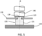
- FIG 5 illustrates this method according to the prior art of fixing a rigid plate 130 on a wall 110 with the aid of a pin 120.
- figure 5 is a sectional view of such a plate 130 fixed on the pin 120 at the end of this method according to the prior art.
- rigid plate is meant a plate which does not substantially deform during the process of crushing the pin 120, that is to say not visibly to the naked eye.
- the pin 120 extends in a longitudinal direction B.
- the distal portion 123 of the pin 120 is inserted into a hole 138 of the plate 130 so that the distal portion 123 has passed through the hole 138 and protrudes from the hole 138.
- proximal 121 of the pin is thus between the plate 130 and the wall 110.
- the proximal portion 121 can not pass through the hole 138 because its cross section is greater than the section of the hole 138.
- the plate 130 is thus maintained at the interface between the proximal portion 121 and the distal portion 123 of the peg.
- the heated face of a rivet 140 is pressed against the distal portion 123 by moving this rivet 140 along the longitudinal axis B towards the wall 110. Under the effect of pressure and heat, the distal portion 123 deforms while being sandwiched and crushed between the plate 130 and the rivet 140, and spreads on the plate 130 around the hole 138. The distal portion 123 is thus taken as an anvil between the plate 130 and the rivet 140.
- the proximal portion 121 having been slightly heated compared to the distal portion 123 and having been partially protected from the action of the rivet 140 by the plate 130, the proximal portion 121 is substantially not deformed. Then push aside the rivet 140 so as to limit the spreading of the distal portion 123 and to let this distal portion 123 to cool.
- the dashed lines represent the rivet 140 in this remote position.
- the pin 120 After cooling, the pin 120 has the shape of a mushroom whose head is the distal distal portion 123 and the foot is the proximal portion 121.
- the wall 130 is then maintained at the interface of the proximal portion 121 and the In fact, since the distal portion 123 extends laterally beyond the hole 138 of the plate 130, this distal portion can no longer slide out of the hole 138.
- the above method is repeated for each of the pins on which the plate is mounted. In this case, the pieces are successively crushed. Alternatively all the pins are simultaneously deformed and crushed by heating pins against the plate.
- the element that one wishes to fix on the pins is not a rigid plate but a more flexible element.
- this element is a membrane, for example a fabric with fibers.
- the flexibility of the element prohibits the distal portion is flattened by being crushed between this element and the rivet.
- the distal portion, and also the proximal portion deform undesirably.
- the proximal portion is crushed and shortened, or the proximal portion is bent laterally.
- such an element can not be properly maintained on a pin at a predetermined distance from the wall which is the height of the proximal portion.
- the pin and / or the element is shaped so that during the movement of the rivet, the distal portion is not crushed between this element and the rivet, even if the element is a rigid plate. This would be the case, for example, if the height-to-diameter ratio of the pin is high enough to produce a buckling of the proximal portion, or if the pin is not aligned with the direction of the compressive force applied by the riveting. In this case the pawn would be damaged and the element could not be held correctly on the pawn.
- the present invention aims to remedy these disadvantages.
- the aim of the invention is to propose a method that makes it possible to stably fix an element on a pin, and by extension on a plurality of pins.
- the combination of heating a portion of the distal portion and the pressure on this molten portion allows to deform this portion by free winding into a head, without constraint by the element.
- An undesirable deformation of the pion makes it unfit to fix the element stably.
- the element is fixed stably on the pin.
- the wall has a plurality of pions, and immediately after step (a1), a surface equalization step (b1) is carried out on a first group of pions and then in a step ( b2) step (a2) is carried out on each of the pions of the first group, this surface equalization step consisting in applying a determined pressure to compensate for the fact that all the ends of the traversing portions of the pions of the first group are not coplanar.
- a surface equalization step (b3) is carried out on a second group of pions distinct from the first group, then in a step (b4) the step (a2) on each of the pions of the second group, this surface equalization step of applying a determined pressure to compensate for the fact that all the ends of the through portions of the pions of the second group are not coplanar.
- step (b5) is carried out in which the steps (b3) and (b4) are iterated with another group of the pions.
- step (b6) is carried out in which step (b5) is iterated until the element is fixed on all the pins.
- Damage is understood to mean a deformation of the pin that renders it unsuitable to fix the element stably on this pin (for example because the proximal portion of the pin (defined above) becomes twisted, inclined, or deformed by another undesirable way.
- the element is thus fixed in a stable manner on each of the pieces.
- the invention also relates to a tank with a wall having at least one plastic pin, a through portion passing through an element.
- a portion of this through portion is deformed by free winding around the pin to form a pin head configured to hold the member on the pin.
- a wall 10 of a tank is considered.
- One or more plastic pins 20 extend along a longitudinal axis A which is substantially perpendicular to the surface of the wall 10 at the interface of the pin 20 with the wall 10.
- Figure 1A is a longitudinal sectional view of such a pin 20.
- this or these pins 20 are located on an inner wall of the tank.
- An element 30 is mounted on the pin 20 by threading the pin 20 through a pre-existing orifice on the element 30 and which passes through the element 30. If the element 30 is a woven piece, for example a fiber fabric, this orifice is one of the stitches of this element. If the element 30 is a nonwoven part, for example a sheet of plastic or metal, this orifice is a hole drilled or molded in this element 30.
- the element 30 is mounted on the pin 20 by piercing this element 30 by the pin 20.
- the pin 20 has a through portion 23 which is the portion of the pin 20 which is furthest from the wall 10 (distal portion of the pin 20), and which has passed through the member 30 during the mounting of the member 30 on the pion 20 (step (a1) of the method according to the invention).
- the proximal portion 21 of the pin 20 designates the other portion of the pin 20, which is located between the wall 10 and the element 30.
- the pin 20 is shaped so that it holds the element 30 at a fixed distance from the wall 10, namely the height (measured along the longitudinal axis A) of the proximal portion 21.
- the proximal portion 21 of the pin 20 can not pass through an orifice in the element 30 while the part distal 23 can pass through this orifice in the element 30.
- the pin flares from its distal portion 23 towards its proximal portion 21 by a conical portion located at the interface between these two parts.
- the rivet 40 has a face (contact face 43) which is intended to be heated and applied against the distal portion 23 so as to deform.
- This contact face 43 may be flat or convex.
- the element 30 is a membrane, that is to say an element of which one of the spatial dimensions (thickness) is much smaller in front of the other two, and whose compressive rigidity is much lower than the tensile rigidity .
- this element 30 is a heating membrane, and the wall 10 is part of a reservoir for containing a liquid, for example urea.
- the invention also applies to the case where the element 30 is not a membrane, for example is a rigid plate whose rigidity is at least equal to that of the pin 20.
- a portion 235 of the through portion 23 is melted and the molten portion 235 is pressed so that the fused portion 235 winds freely around the pin 20 so as to form a pion head configured to maintain the element 30 on the pin 20 (step (a2)).
- the portion 235 may represent only part or all of the through portion 23.
- melt is meant that the material of the portion 235 is heated to a heating temperature T where it has a pasty state intermediate between a solid state and a liquid state.
- this heating of the portion 235 is performed by heating the contact face 43 of the rivet 40 to the heating temperature T and placing it in contact with the end of the through portion 23. Then press the rivet 40 against the end of the through portion 23 of the pin 20 so that the contact face 43 exerts, along the longitudinal axis A, a pressure P on this through portion 23.
- This step is illustrated in FIG. Figure 1B .
- the heating temperature T is close to the melting temperature T F of the material constituting the pin 20.
- close is meant that the heating temperature T is in a range of 50 ° C around the melting temperature T F .
- the material deforms more easily and rapidly under the effect of the pressure exerted on the pin 20 by the rivet 40.
- the heating temperature T is greater than the melting temperature T F.
- the portion 235 is melted at a constant temperature T c , which is the heating temperature.
- Constant temperature means a temperature that varies little around the value T c , the temperature being in practice regulated by a control device. Thus, portion 235 is melted at a substantially constant temperature which oscillates around the average temperature T c .
- the temperature T c is of the order of 200 ° C., and the variations around this temperature are of the order of ⁇ 15 ° C.
- the portion 235 is brought rapidly to the temperature where it takes a pasty state and deforms before the remainder of the through portion 23 (located closer to the proximal portion 21) is heated.
- the deformation of the proximal portion 21 is further minimized.
- the temperature T varies during the period of contact between the pin 20 and the rivet 40.
- the temperature T increases with the duration of contact between the pin 20 and the rivet 40.
- the contact pressure P between the rivet 40 and the pin 20 varies over the period of contact between the rivet 40 and the pin 20, up to a maximum value P 0 .
- the molten portion 235 is pressed progressively, with a pressure P or a determined speed V.
- the combination of the heating temperature T of the rivet 40 and the pressure P exerted by the rivet 40 on the portion 235 leads to a deformation of the portion 235 such that the proximal portion 21 is substantially not deformed, and is essentially compressed only along the longitudinal axis A.
- the temperature T of the rivet 40 is sufficiently high (and / or the pressure P exerted by the rivet 40 or the speed of advancement V of the rivet 40 is sufficiently small) to allow time for the portion 235 to deform laterally (radially outwardly) while the proximal portion 21 does not deform undesirably.
- the pressure P exerted by the rivet 40 on the portion 235 or the forward speed V of the rivet 40 is chosen as a function of the temperature T c so that the proximal portion 21 of the stud 20 is little or not distorted.
- the proximal portion 21 does not flare up (buckling denotes, in known manner, the instability phenomenon of a structure subjected to a normal compressive force that deforms globally perpendicular to the direction of compression) or does not does not lean appreciably under the action of the snap 40.
- the membrane 30 remains positioned at a predetermined distance from the wall 10, at the interface between the through portion 23 and the proximal portion 21 of the pin 20, the membrane 30 being maintained at this distance by the through portion 23 deformed.
- the area of the maximum cross section of the through portion 23 is strictly less than the minimum cross sectional area of the proximal portion 21 of the pin 20.
- This geometry of the pin 20 contributes to keeping the membrane 30 at its initial position (before step (a2)).
- the pin 20 is cylindrical and has a shoulder at the interface between its through portion 23 and its proximal portion 21, the diameter of the cross section of the through portion 23 being smaller than the diameter of the cross section of the proximal portion. 21.
- the pin 20 is conical and flares from its through portion 23 to its proximal portion 21.
- the pin 20 has on its proximal portion 21 fins 22 which extend longitudinally from the wall and radially outwardly. These fins 22 contribute to keeping the pin 20 aligned with the longitudinal direction along the axis A. These fins are visible on some of the pins on the figure 4 .
- step (a2) the rivet 40 is moved away so that it is no longer in contact with the peg 20. This situation is illustrated in FIG. Figure 1C .
- molten portion 235 is allowed to cool and freeze more quickly in its shape taken after compression by rivet 40.
- the fused portion 235 of the pin 20 winds freely, which means that no other part than the pin 20 interferes with this winding.
- the element 30, whether flexible or rigid, does not interfere with this winding.
- the figure 2 is a longitudinal sectional view (in a plane containing the longitudinal axis A) of a pin 20 after its deformation by a rivet 40 according to the method of the invention.
- the pin 20 has a conical shape.
- the pin head formed by the deformation of the molten portion 235 has a torus shape 24 at the end of the winding process and extends radially outwardly from the remainder of the through portion (23).
- This torus 24 is centered on the longitudinal axis A and has an annular bead shape.
- the central portion of the through portion 23 is hollowed to form a depression centered on the longitudinal axis A.
- the membrane 30 is thus held on the pin 20 by the torus 24 since the torus 24 extends laterally (radially) beyond the orifice of the membrane 30 through which the through portion 23 was passed before its deformation by the method according to the invention.
- the torus 24 is attached to the circumference of the distal end of the remainder of the through portion 23 by an annular junction zone 25, visible on the figure 2 .
- the tests carried out by the inventors show that the minimum thickness E of the junction zone 25 must be greater than a threshold value Es to withstand a tearing force F A.
- the threshold thickness Es depends on the material of the pin 20. For a tearing force F A equal to 140 N and in pin 20 made of high density polyethylene (referenced HDPE CC252), the threshold thickness Es is equal to 200 ⁇ m (microns ).
- the combination of the contact pressure P exerted by the rivet 40 on the pin 20 and the heating temperature T of the rivet 40 which is such that the counter 20 is deformed by free winding into a torus centered on the longitudinal axis A may vary.
- the values of the contact pressure P and the heating temperature T can not therefore be unique and fixed for the entire range of materials capable of constituting the pion.
- the proximal portion 21 of the pin 20 is of non-zero length, as shown in the figures.
- the proximal portion 21 is of zero length.
- the membrane 30 is then fixed against the wall 10 once the fixing process according to the invention is completed.
- the invention also relates to a method for fixing an element 30 to a plurality of pins 20 extending from a wall 10.
- step (a1) described above is first carried out for each of the pins 20, so that the traversing portion 23 of each pin 20 passes through the element 30, while the proximal portion 21 of each pin 20 is located between the element 30 and the wall 10.
- a surface equalization step (b1) is performed on a first group of these pins 20.
- Step (b1) consists in applying a determined pressure on the first group only of the pins 20 to compensate for the fact that all the ends of the through portions 23 of the pions 20 of the first group are not necessarily coplanar, that is to say say are not all in the same plane. This is generally the case either because the pins 20 do not have the same height (length along the longitudinal axis A), or because the surface of the wall 10 carrying the pins 20 is not flat.
- This step avoids that under the action of the rivet 40 some pins 20 are too high pressure and are undesirably deformed.
- step (b1) several bouterolles 40, each intended to compress one of the pins 20, are approached simultaneously, that is to say the bouterolles 40 are translated together in one and the same movement along the longitudinal axis A until a first group of pins 20 comes into contact substantially simultaneously with the snap-fasteners 40.
- the contact surfaces 43 of the snaps 40 are all located in the same plane.
- the caps 40 are all mounted on the same support which is translated.
- a single bolt 40 with a large contact surface 43 capable of touching each of the pins is translated.
- the first group of pins 20 thus groups the pins 20, which, when lowering the or bouterolles 40 (or more generally a tool), the traversing portion 23 is in contact with the or bouterolles 40 without being compressed in its longitudinal direction undesirably, advantageously without being permanently compressed.
- the movement of "lowering" or the bouterolles 40 designates bringing these bouterolles 40 closer to the wall 10 carrying the pins 20.
- the rivet 40 is not necessarily heated.
- the rivet 40 is heated before step (b1) to a heating temperature, and remains heated at this heating temperature during all the steps of the method according to the invention.
- it avoids cooling and heating phases between these steps, and saves time in the treatment of pins 20.
- step (b2) the step (a2) described above is performed on each of the pawns 20 of the first group.
- the element 30 is thus fixed on all the pins 20 of the first group, these pins 20 having been deformed during the step (b2).
- the element 30 is fixed on all the pins 20 at the end of step (b2), and the process according to the invention is stopped.
- Step (b3) consists in applying a determined pressure on the second group of pins 20 to compensate for the fact that all the ends of the through portions 23 of the pins 20 of the first group are not necessarily coplanar.
- step (b4) is performed step (a2) on each of the pawns (20) of the second group.
- the element 30 is thus fixed on all the pins 20 of the second group, these pins 20 having been deformed during step (b4).
- step (b2) the tool 40 may come into contact with the second group of pegs simply because the molten portion 23 of the pegs 20 of the first group of pieces has been pressed. during step (b2).
- step (b3) is thus performed during the performance of step (b2), and step (b4) is directly carried out.
- a step (b5) is carried out in which iterates the steps (b3) and (b4) with another group of the pions (20).
- a step is carried out ( b6) in which the step (b5) is iterated until the element 30 is fixed on all the pins 20.
- the figure 4 illustrates a wall 10 which has on its inner surface several pins 20 which extend substantially along a longitudinal axis A. This figure shows the state of the pins 20 between step (b2) and step (b3).
- the membrane 30 is fixed on a first group of pins 20, and is not fixed on a second group of pins 20.
- the caps 40 are shown in dashed lines.
- the first group of pawns 20 is located on the left, the second group of pawns 20 is located on the right on the figure 4 .
- the invention also relates to a tank with a wall 10 having at least one plastic pin 20, a through portion 23 passes through a member 30, a portion 235 of this through portion 23 is deformed by free winding around the pin 20 to form a pin head configured to hold the member 30 on the pin 20.
Landscapes
- Engineering & Computer Science (AREA)
- Mechanical Engineering (AREA)
- Physics & Mathematics (AREA)
- Thermal Sciences (AREA)
- High Energy & Nuclear Physics (AREA)
- Plasma & Fusion (AREA)
- Lining Or Joining Of Plastics Or The Like (AREA)
- Casting Or Compression Moulding Of Plastics Or The Like (AREA)
- Connection Of Plates (AREA)
Claims (15)
- Verfahren zum Befestigen eines Elements (30) an einer Wand (10) eines Vorratsbehälters, wobei die Wand (10) mindestens einen Stift (20) aus Kunststoffmaterial aufweist, wobei das Verfahren die folgenden Schritte umfasst:(a1) Montieren des Elements (30) auf dem mindestens einen Stift (20), sodass ein durchgehender Teil (23) des Stifts (20) durch das Element (30) dringt,(a2) Aufschmelzen eines Abschnitts (235) des durchgehenden Teils (23) und Drücken auf den geschmolzenen Abschnitt (235), sodass der geschmolzene Abschnitt (235) sich frei um den mindestens einen Stift (20) aufrollt, um einen Stiftkopf zu bilden, der ausgelegt ist, um das Element (30) auf dem Stift (20) zu halten.
- Verfahren nach Anspruch 1, dadurch gekennzeichnet, dass der Abschnitt (235) bei einer konstanten Temperatur Tc geschmolzen wird.
- Verfahren nach Anspruch 2, dadurch gekennzeichnet, dass mit einem bestimmten Druck P oder einer bestimmten Geschwindigkeit V schrittweise auf den geschmolzenen Abschnitt (235) gedrückt wird.
- Verfahren nach Anspruch 3, dadurch gekennzeichnet, dass der Druck P oder die Geschwindigkeit V in Abhängigkeit von der Temperatur Tc ausgewählt wird, sodass der proximale Teil (21) des Stifts (20), der der Teil des Stifts (20) ist, der nicht durch das Element (20) dringt, kaum oder gar nicht verformt wird.
- Verfahren nach einem der vorangehenden Ansprüche, dadurch gekennzeichnet, dass der Stiftkopf am Ende des Aufrollvorgangs einen Torus ausbildet und sich vom Rest des durchgehenden Teils (23) des Stifts (20) radial nach außen erstreckt.
- Verfahren nach einem der vorangehenden Ansprüche, dadurch gekennzeichnet, dass sich der mindestens eine Stift (20) auf einer Innenwand des Vorratsbehälters befindet.
- Verfahren nach einem der vorangehenden Ansprüche, dadurch gekennzeichnet, dass das Element (30) flexibler ist als der mindestens eine Stift (20).
- Verfahren nach Anspruch 7, dadurch gekennzeichnet, dass das Element (30) eine Membran ist.
- Verfahren nach einem der vorangehenden Ansprüche, dadurch gekennzeichnet, dass die Wand (10) eine Vielzahl der Stifte (20) aufweist und dass unmittelbar nach dem Schritt (a1) ein Schritt (b1) ausgeführt wird, bei dem eine Oberflächenglättung auf einer ersten Gruppe der Stifte (20) erfolgt, und dann in einem Schritt (b2) der Schritt (a2) an jedem der Stifte (20) der ersten Gruppe ausgeführt wird, wobei der Schritt (b1) der Oberflächenglättung darin besteht, einen bestimmten Druck auszuüben, um auszugleichen, dass nicht alle Enden der durchgehenden Teile (23) der Stifte (20) der ersten Gruppe koplanar sind.
- Verfahren nach dem vorangehenden Anspruch, dadurch gekennzeichnet, dass in dem Schritt (b1) ein Werkzeug (40) auf die erste Gruppe der Stifte (20) abgesenkt wird, sodass jeder der Teile (23) der Stifte (20) der ersten Gruppe im Kontakt mit dem Werkzeug (40) steht, ohne auf unerwünschte Weise entlang seiner Längsrichtung komprimiert zu sein.
- Verfahren nach Anspruch 9 oder 10, dadurch gekennzeichnet, dass nach dem Schritt (b2) ein Schritt (b3) der Oberflächenglättung auf einer zweiten Gruppe der Stifte (20) erfolgt, die sich von der ersten Gruppe unterscheidet, und dann in einem Schritt (b4) der Schritt (a2) auf jedem der Stifte (20) der zweiten Gruppe ausgeführt wird, wobei der Schritt (b3) der Oberflächenglättung darin besteht, einen bestimmten Druck auszuüben, um auszugleichen, dass nicht alle Enden der durchgehenden Teile (23) der Stifte (20) der zweiten Gruppe koplanar sind.
- Verfahren nach dem vorangehenden Anspruch, dadurch gekennzeichnet, dass in dem Schritt (b3) ein Werkzeug (40) auf die zweite Gruppe abgesenkt wird, sodass jeder der Teile (23) der Stifte (20) der zweiten Gruppe im Kontakt mit dem Werkzeug (40) steht, ohne auf unerwünschte Weise entlang seiner Längsrichtung komprimiert zu sein.
- Verfahren nach Anspruch 11 oder 12, dadurch gekennzeichnet, dass nach Schritt dem (b4) ein Schritt (b5) ausgeführt wird, in dem die Schritte (b3) und (b4) mit einer anderen Gruppe der Stifte (20) wiederholt werden.
- Verfahren nach dem vorangehenden Anspruch, dadurch gekennzeichnet, dass nach dem Schritt (b5) ein Schritt (b6) ausgeführt wird, in dem der Schritt (b5) wiederholt wird, bis das Element (30) an den Stiften (20) befestigt ist.
- Vorratsbehälter mit einer Wand (10), aufweisend mindestens einen Stift (20) aus Kunststoffmaterial, von dem ein durchgehender Teil (23) durch ein Element (30) dringt, wobei mindestens ein Stift (20) dadurch gekennzeichnet ist, dass ein Abschnitt (235) des durchgehenden Teils (23) durch freies Aufrollen um mindestens einen Stift (20) verformt ist, um einen Stiftkopf auszubilden, der ausgelegt ist, um das Element (30) auf dem Stift (20) zu halten.
Applications Claiming Priority (2)
| Application Number | Priority Date | Filing Date | Title |
|---|---|---|---|
| FR1363748 | 2013-12-31 | ||
| PCT/FR2014/053531 WO2015101746A1 (fr) | 2013-12-31 | 2014-12-23 | Procede pour la fixation d'un element sur un pion |
Publications (3)
| Publication Number | Publication Date |
|---|---|
| EP3089859A1 EP3089859A1 (de) | 2016-11-09 |
| EP3089859B1 true EP3089859B1 (de) | 2019-07-31 |
| EP3089859B8 EP3089859B8 (de) | 2019-09-18 |
Family
ID=52462336
Family Applications (1)
| Application Number | Title | Priority Date | Filing Date |
|---|---|---|---|
| EP14835484.8A Active EP3089859B8 (de) | 2013-12-31 | 2014-12-23 | Verfahren zum befestigen eines elements an einem stift |
Country Status (6)
| Country | Link |
|---|---|
| US (1) | US20160318242A1 (de) |
| EP (1) | EP3089859B8 (de) |
| JP (1) | JP6524103B2 (de) |
| KR (1) | KR20160104037A (de) |
| CN (1) | CN105848858B (de) |
| WO (1) | WO2015101746A1 (de) |
Families Citing this family (2)
| Publication number | Priority date | Publication date | Assignee | Title |
|---|---|---|---|---|
| DE102019112174A1 (de) * | 2019-05-09 | 2020-11-12 | Paul Hettich Gmbh & Co. Kg | Verfahren zum Fixieren eines Kunststoffbauteils eines Beschlages an einem Metallteil und Beschlag für Möbel oder Haushaltsgeräte |
| CN113967719A (zh) * | 2021-11-08 | 2022-01-25 | 南昌锌之蓝节能环保新材料有限公司 | 一种可省去铆钉的盘扣式脚手架横杆板销自动安装系统 |
Family Cites Families (10)
| Publication number | Priority date | Publication date | Assignee | Title |
|---|---|---|---|---|
| JPS6062325U (ja) * | 1983-10-06 | 1985-05-01 | 山川工業株式会社 | 自動車用燃料タンク |
| JPS63212533A (ja) * | 1987-02-28 | 1988-09-05 | Showa Denko Kk | 合成樹脂製タンクの製造方法 |
| US5308427A (en) * | 1992-09-28 | 1994-05-03 | Ford Motor Company | Method for fastening plastic articles |
| US20030044553A1 (en) * | 2001-08-23 | 2003-03-06 | Ravi Ramanathan | Fuel tanks |
| JP4681257B2 (ja) * | 2004-06-03 | 2011-05-11 | 株式会社ニフコ | 保護板取付構造 |
| JP2008162125A (ja) * | 2006-12-28 | 2008-07-17 | Nidec Copal Corp | 熱カシメ連結構造及び熱カシメ連結方法 |
| JP2010208173A (ja) * | 2009-03-11 | 2010-09-24 | Toyoda Gosei Co Ltd | 熱カシメ構造体 |
| CN201573339U (zh) * | 2009-09-28 | 2010-09-08 | 上海施耐德低压终端电器有限公司 | 一种塑铆装置 |
| DE102010032279B4 (de) * | 2010-07-26 | 2012-09-06 | Kautex Textron Gmbh & Co. Kg | Verfahren zur Nietbefestigung eines Zubehörteils |
| JP5333584B2 (ja) * | 2010-12-08 | 2013-11-06 | トヨタ自動車株式会社 | 部材の接続方法 |
-
2014
- 2014-12-23 WO PCT/FR2014/053531 patent/WO2015101746A1/fr not_active Ceased
- 2014-12-23 KR KR1020167020668A patent/KR20160104037A/ko not_active Ceased
- 2014-12-23 JP JP2016543658A patent/JP6524103B2/ja not_active Expired - Fee Related
- 2014-12-23 CN CN201480071179.8A patent/CN105848858B/zh active Active
- 2014-12-23 US US15/109,016 patent/US20160318242A1/en not_active Abandoned
- 2014-12-23 EP EP14835484.8A patent/EP3089859B8/de active Active
Non-Patent Citations (1)
| Title |
|---|
| None * |
Also Published As
| Publication number | Publication date |
|---|---|
| US20160318242A1 (en) | 2016-11-03 |
| JP6524103B2 (ja) | 2019-06-05 |
| CN105848858B (zh) | 2018-02-23 |
| JP2017508923A (ja) | 2017-03-30 |
| EP3089859A1 (de) | 2016-11-09 |
| CN105848858A (zh) | 2016-08-10 |
| EP3089859B8 (de) | 2019-09-18 |
| WO2015101746A1 (fr) | 2015-07-09 |
| KR20160104037A (ko) | 2016-09-02 |
Similar Documents
| Publication | Publication Date | Title |
|---|---|---|
| EP1892120B1 (de) | Speiche für ein Speichenrad, Herstellungsverfahren und Rad mit mindestens einer solchen Speiche | |
| EP2140151A2 (de) | Hochleistungsfähige blindnietvorrichtung, insbesondere zur strukturellen befestigung | |
| WO2009010698A2 (fr) | Systeme de serrage a declenchement automatique pour un collier de serrage elastique | |
| EP2002164B1 (de) | Anquetschbares rohrverbindungszubehörteil | |
| FR2972238A1 (fr) | Procede de pose d'un rivet a ame creuse, rivet et outil de pose adaptes | |
| EP2552622B1 (de) | Niet und nietsetzvorrichtung | |
| EP3089859B1 (de) | Verfahren zum befestigen eines elements an einem stift | |
| EP2036697A1 (de) | Verfahren zur Herstellung von Rohren durch Schweißen | |
| CA2720457C (fr) | Procede de fabrication de tubes par soudage | |
| WO2015158983A1 (fr) | Assemblage riveté et procédé de fabrication associé | |
| WO2010061094A1 (fr) | Dispositif de soudage a double épaulement | |
| WO2016192888A1 (fr) | Profilé creux tel qu'un tube réalisé en matériaux composite thermodurcissable et son procédé | |
| EP2657542B1 (de) | Verfahren zum Befestigen einer Nietmutter ohne Kopf auf einem Sandwichpaneel | |
| EP1958715B1 (de) | Verfahren zum Zusammenbau von mindestens zwei Elementen mit Hilfe eines Blindniets | |
| EP1379342B1 (de) | Verfahren zum aufweiten einer buchse, insbesondere eine buchse eines elastischen gelenkes, sowie dadurch erhaltene buchse und elastisches gelenk | |
| EP2265445B1 (de) | Speichenradspeiche sowie entsprechendes rad und verfahren dafür | |
| FR2732417A1 (fr) | Piece d'insertion metallique pour thermoplastique, a tenue mecanique renforcee | |
| EP2886883B1 (de) | Selbstbohrendes Schnellbauteil zum Befestigen und Zusammenbauen | |
| EP3061595B1 (de) | Herstellungsverfahren von hohlprofilen aus verbundmaterialien | |
| EP3724523B1 (de) | Befestigungsvorrichtung, befestigungsanordnung mit einer solchen vorrichtung und verfahren zur herstellung einer solchen anordnung | |
| EP2620329B1 (de) | Hizte- und Schallschutzverfahren einer Strukturwand eines Kraftfahrzeuges | |
| WO2024241294A1 (fr) | Biellette comprenant un pivot à rotule | |
| EP0572296B1 (de) | System zum chemischen Einmauern von einem Befestigungselement in einem hohlen Material | |
| FR3103769A1 (fr) | Bras d'essuie-glace | |
| FR2959431A1 (fr) | Dispositif d'assemblage a sertir |
Legal Events
| Date | Code | Title | Description |
|---|---|---|---|
| PUAI | Public reference made under article 153(3) epc to a published international application that has entered the european phase |
Free format text: ORIGINAL CODE: 0009012 |
|
| 17P | Request for examination filed |
Effective date: 20160708 |
|
| AK | Designated contracting states |
Kind code of ref document: A1 Designated state(s): AL AT BE BG CH CY CZ DE DK EE ES FI FR GB GR HR HU IE IS IT LI LT LU LV MC MK MT NL NO PL PT RO RS SE SI SK SM TR |
|
| AX | Request for extension of the european patent |
Extension state: BA ME |
|
| DAX | Request for extension of the european patent (deleted) | ||
| GRAP | Despatch of communication of intention to grant a patent |
Free format text: ORIGINAL CODE: EPIDOSNIGR1 |
|
| STAA | Information on the status of an ep patent application or granted ep patent |
Free format text: STATUS: GRANT OF PATENT IS INTENDED |
|
| INTG | Intention to grant announced |
Effective date: 20180312 |
|
| GRAJ | Information related to disapproval of communication of intention to grant by the applicant or resumption of examination proceedings by the epo deleted |
Free format text: ORIGINAL CODE: EPIDOSDIGR1 |
|
| STAA | Information on the status of an ep patent application or granted ep patent |
Free format text: STATUS: REQUEST FOR EXAMINATION WAS MADE |
|
| INTC | Intention to grant announced (deleted) | ||
| GRAP | Despatch of communication of intention to grant a patent |
Free format text: ORIGINAL CODE: EPIDOSNIGR1 |
|
| STAA | Information on the status of an ep patent application or granted ep patent |
Free format text: STATUS: GRANT OF PATENT IS INTENDED |
|
| INTG | Intention to grant announced |
Effective date: 20180927 |
|
| GRAJ | Information related to disapproval of communication of intention to grant by the applicant or resumption of examination proceedings by the epo deleted |
Free format text: ORIGINAL CODE: EPIDOSDIGR1 |
|
| STAA | Information on the status of an ep patent application or granted ep patent |
Free format text: STATUS: REQUEST FOR EXAMINATION WAS MADE |
|
| GRAP | Despatch of communication of intention to grant a patent |
Free format text: ORIGINAL CODE: EPIDOSNIGR1 |
|
| STAA | Information on the status of an ep patent application or granted ep patent |
Free format text: STATUS: GRANT OF PATENT IS INTENDED |
|
| INTC | Intention to grant announced (deleted) | ||
| INTG | Intention to grant announced |
Effective date: 20190225 |
|
| GRAS | Grant fee paid |
Free format text: ORIGINAL CODE: EPIDOSNIGR3 |
|
| GRAA | (expected) grant |
Free format text: ORIGINAL CODE: 0009210 |
|
| STAA | Information on the status of an ep patent application or granted ep patent |
Free format text: STATUS: THE PATENT HAS BEEN GRANTED |
|
| AK | Designated contracting states |
Kind code of ref document: B1 Designated state(s): AL AT BE BG CH CY CZ DE DK EE ES FI FR GB GR HR HU IE IS IT LI LT LU LV MC MK MT NL NO PL PT RO RS SE SI SK SM TR |
|
| REG | Reference to a national code |
Ref country code: CH Ref legal event code: EP Ref country code: GB Ref legal event code: FG4D Free format text: NOT ENGLISH |
|
| REG | Reference to a national code |
Ref country code: AT Ref legal event code: REF Ref document number: 1160459 Country of ref document: AT Kind code of ref document: T Effective date: 20190815 |
|
| REG | Reference to a national code |
Ref country code: IE Ref legal event code: FG4D Free format text: LANGUAGE OF EP DOCUMENT: FRENCH |
|
| REG | Reference to a national code |
Ref country code: DE Ref legal event code: R096 Ref document number: 602014050998 Country of ref document: DE |
|
| RAP2 | Party data changed (patent owner data changed or rights of a patent transferred) |
Owner name: PLASTIC OMNIUM ADVANCED INNOVATION AND RESEARCH |
|
| REG | Reference to a national code |
Ref country code: CH Ref legal event code: PK Free format text: RECTIFICATION B8 |
|
| REG | Reference to a national code |
Ref country code: NL Ref legal event code: MP Effective date: 20190731 |
|
| REG | Reference to a national code |
Ref country code: LT Ref legal event code: MG4D |
|
| REG | Reference to a national code |
Ref country code: AT Ref legal event code: MK05 Ref document number: 1160459 Country of ref document: AT Kind code of ref document: T Effective date: 20190731 |
|
| PG25 | Lapsed in a contracting state [announced via postgrant information from national office to epo] |
Ref country code: FI Free format text: LAPSE BECAUSE OF FAILURE TO SUBMIT A TRANSLATION OF THE DESCRIPTION OR TO PAY THE FEE WITHIN THE PRESCRIBED TIME-LIMIT Effective date: 20190731 Ref country code: HR Free format text: LAPSE BECAUSE OF FAILURE TO SUBMIT A TRANSLATION OF THE DESCRIPTION OR TO PAY THE FEE WITHIN THE PRESCRIBED TIME-LIMIT Effective date: 20190731 Ref country code: SE Free format text: LAPSE BECAUSE OF FAILURE TO SUBMIT A TRANSLATION OF THE DESCRIPTION OR TO PAY THE FEE WITHIN THE PRESCRIBED TIME-LIMIT Effective date: 20190731 Ref country code: AT Free format text: LAPSE BECAUSE OF FAILURE TO SUBMIT A TRANSLATION OF THE DESCRIPTION OR TO PAY THE FEE WITHIN THE PRESCRIBED TIME-LIMIT Effective date: 20190731 Ref country code: NL Free format text: LAPSE BECAUSE OF FAILURE TO SUBMIT A TRANSLATION OF THE DESCRIPTION OR TO PAY THE FEE WITHIN THE PRESCRIBED TIME-LIMIT Effective date: 20190731 Ref country code: BG Free format text: LAPSE BECAUSE OF FAILURE TO SUBMIT A TRANSLATION OF THE DESCRIPTION OR TO PAY THE FEE WITHIN THE PRESCRIBED TIME-LIMIT Effective date: 20191031 Ref country code: NO Free format text: LAPSE BECAUSE OF FAILURE TO SUBMIT A TRANSLATION OF THE DESCRIPTION OR TO PAY THE FEE WITHIN THE PRESCRIBED TIME-LIMIT Effective date: 20191031 Ref country code: LT Free format text: LAPSE BECAUSE OF FAILURE TO SUBMIT A TRANSLATION OF THE DESCRIPTION OR TO PAY THE FEE WITHIN THE PRESCRIBED TIME-LIMIT Effective date: 20190731 Ref country code: PT Free format text: LAPSE BECAUSE OF FAILURE TO SUBMIT A TRANSLATION OF THE DESCRIPTION OR TO PAY THE FEE WITHIN THE PRESCRIBED TIME-LIMIT Effective date: 20191202 |
|
| PG25 | Lapsed in a contracting state [announced via postgrant information from national office to epo] |
Ref country code: IS Free format text: LAPSE BECAUSE OF FAILURE TO SUBMIT A TRANSLATION OF THE DESCRIPTION OR TO PAY THE FEE WITHIN THE PRESCRIBED TIME-LIMIT Effective date: 20191130 Ref country code: GR Free format text: LAPSE BECAUSE OF FAILURE TO SUBMIT A TRANSLATION OF THE DESCRIPTION OR TO PAY THE FEE WITHIN THE PRESCRIBED TIME-LIMIT Effective date: 20191101 Ref country code: ES Free format text: LAPSE BECAUSE OF FAILURE TO SUBMIT A TRANSLATION OF THE DESCRIPTION OR TO PAY THE FEE WITHIN THE PRESCRIBED TIME-LIMIT Effective date: 20190731 Ref country code: LV Free format text: LAPSE BECAUSE OF FAILURE TO SUBMIT A TRANSLATION OF THE DESCRIPTION OR TO PAY THE FEE WITHIN THE PRESCRIBED TIME-LIMIT Effective date: 20190731 Ref country code: AL Free format text: LAPSE BECAUSE OF FAILURE TO SUBMIT A TRANSLATION OF THE DESCRIPTION OR TO PAY THE FEE WITHIN THE PRESCRIBED TIME-LIMIT Effective date: 20190731 Ref country code: RS Free format text: LAPSE BECAUSE OF FAILURE TO SUBMIT A TRANSLATION OF THE DESCRIPTION OR TO PAY THE FEE WITHIN THE PRESCRIBED TIME-LIMIT Effective date: 20190731 |
|
| PG25 | Lapsed in a contracting state [announced via postgrant information from national office to epo] |
Ref country code: TR Free format text: LAPSE BECAUSE OF FAILURE TO SUBMIT A TRANSLATION OF THE DESCRIPTION OR TO PAY THE FEE WITHIN THE PRESCRIBED TIME-LIMIT Effective date: 20190731 |
|
| PG25 | Lapsed in a contracting state [announced via postgrant information from national office to epo] |
Ref country code: IT Free format text: LAPSE BECAUSE OF FAILURE TO SUBMIT A TRANSLATION OF THE DESCRIPTION OR TO PAY THE FEE WITHIN THE PRESCRIBED TIME-LIMIT Effective date: 20190731 Ref country code: EE Free format text: LAPSE BECAUSE OF FAILURE TO SUBMIT A TRANSLATION OF THE DESCRIPTION OR TO PAY THE FEE WITHIN THE PRESCRIBED TIME-LIMIT Effective date: 20190731 Ref country code: PL Free format text: LAPSE BECAUSE OF FAILURE TO SUBMIT A TRANSLATION OF THE DESCRIPTION OR TO PAY THE FEE WITHIN THE PRESCRIBED TIME-LIMIT Effective date: 20190731 Ref country code: RO Free format text: LAPSE BECAUSE OF FAILURE TO SUBMIT A TRANSLATION OF THE DESCRIPTION OR TO PAY THE FEE WITHIN THE PRESCRIBED TIME-LIMIT Effective date: 20190731 Ref country code: DK Free format text: LAPSE BECAUSE OF FAILURE TO SUBMIT A TRANSLATION OF THE DESCRIPTION OR TO PAY THE FEE WITHIN THE PRESCRIBED TIME-LIMIT Effective date: 20190731 |
|
| PG25 | Lapsed in a contracting state [announced via postgrant information from national office to epo] |
Ref country code: CZ Free format text: LAPSE BECAUSE OF FAILURE TO SUBMIT A TRANSLATION OF THE DESCRIPTION OR TO PAY THE FEE WITHIN THE PRESCRIBED TIME-LIMIT Effective date: 20190731 Ref country code: SK Free format text: LAPSE BECAUSE OF FAILURE TO SUBMIT A TRANSLATION OF THE DESCRIPTION OR TO PAY THE FEE WITHIN THE PRESCRIBED TIME-LIMIT Effective date: 20190731 Ref country code: SM Free format text: LAPSE BECAUSE OF FAILURE TO SUBMIT A TRANSLATION OF THE DESCRIPTION OR TO PAY THE FEE WITHIN THE PRESCRIBED TIME-LIMIT Effective date: 20190731 Ref country code: IS Free format text: LAPSE BECAUSE OF FAILURE TO SUBMIT A TRANSLATION OF THE DESCRIPTION OR TO PAY THE FEE WITHIN THE PRESCRIBED TIME-LIMIT Effective date: 20200224 |
|
| REG | Reference to a national code |
Ref country code: DE Ref legal event code: R097 Ref document number: 602014050998 Country of ref document: DE |
|
| PLBE | No opposition filed within time limit |
Free format text: ORIGINAL CODE: 0009261 |
|
| STAA | Information on the status of an ep patent application or granted ep patent |
Free format text: STATUS: NO OPPOSITION FILED WITHIN TIME LIMIT |
|
| PG2D | Information on lapse in contracting state deleted |
Ref country code: IS |
|
| PG25 | Lapsed in a contracting state [announced via postgrant information from national office to epo] |
Ref country code: IS Free format text: LAPSE BECAUSE OF FAILURE TO SUBMIT A TRANSLATION OF THE DESCRIPTION OR TO PAY THE FEE WITHIN THE PRESCRIBED TIME-LIMIT Effective date: 20191030 |
|
| REG | Reference to a national code |
Ref country code: CH Ref legal event code: PL |
|
| 26N | No opposition filed |
Effective date: 20200603 |
|
| REG | Reference to a national code |
Ref country code: BE Ref legal event code: MM Effective date: 20191231 |
|
| PG25 | Lapsed in a contracting state [announced via postgrant information from national office to epo] |
Ref country code: MC Free format text: LAPSE BECAUSE OF FAILURE TO SUBMIT A TRANSLATION OF THE DESCRIPTION OR TO PAY THE FEE WITHIN THE PRESCRIBED TIME-LIMIT Effective date: 20190731 Ref country code: SI Free format text: LAPSE BECAUSE OF FAILURE TO SUBMIT A TRANSLATION OF THE DESCRIPTION OR TO PAY THE FEE WITHIN THE PRESCRIBED TIME-LIMIT Effective date: 20190731 |
|
| GBPC | Gb: european patent ceased through non-payment of renewal fee |
Effective date: 20191223 |
|
| PG25 | Lapsed in a contracting state [announced via postgrant information from national office to epo] |
Ref country code: GB Free format text: LAPSE BECAUSE OF NON-PAYMENT OF DUE FEES Effective date: 20191223 Ref country code: IE Free format text: LAPSE BECAUSE OF NON-PAYMENT OF DUE FEES Effective date: 20191223 Ref country code: LU Free format text: LAPSE BECAUSE OF NON-PAYMENT OF DUE FEES Effective date: 20191223 |
|
| PG25 | Lapsed in a contracting state [announced via postgrant information from national office to epo] |
Ref country code: BE Free format text: LAPSE BECAUSE OF NON-PAYMENT OF DUE FEES Effective date: 20191231 Ref country code: CH Free format text: LAPSE BECAUSE OF NON-PAYMENT OF DUE FEES Effective date: 20191231 Ref country code: LI Free format text: LAPSE BECAUSE OF NON-PAYMENT OF DUE FEES Effective date: 20191231 |
|
| PG25 | Lapsed in a contracting state [announced via postgrant information from national office to epo] |
Ref country code: CY Free format text: LAPSE BECAUSE OF FAILURE TO SUBMIT A TRANSLATION OF THE DESCRIPTION OR TO PAY THE FEE WITHIN THE PRESCRIBED TIME-LIMIT Effective date: 20190731 |
|
| PG25 | Lapsed in a contracting state [announced via postgrant information from national office to epo] |
Ref country code: MT Free format text: LAPSE BECAUSE OF FAILURE TO SUBMIT A TRANSLATION OF THE DESCRIPTION OR TO PAY THE FEE WITHIN THE PRESCRIBED TIME-LIMIT Effective date: 20190731 Ref country code: HU Free format text: LAPSE BECAUSE OF FAILURE TO SUBMIT A TRANSLATION OF THE DESCRIPTION OR TO PAY THE FEE WITHIN THE PRESCRIBED TIME-LIMIT; INVALID AB INITIO Effective date: 20141223 |
|
| PG25 | Lapsed in a contracting state [announced via postgrant information from national office to epo] |
Ref country code: MK Free format text: LAPSE BECAUSE OF FAILURE TO SUBMIT A TRANSLATION OF THE DESCRIPTION OR TO PAY THE FEE WITHIN THE PRESCRIBED TIME-LIMIT Effective date: 20190731 |
|
| P01 | Opt-out of the competence of the unified patent court (upc) registered |
Effective date: 20230515 |
|
| REG | Reference to a national code |
Ref country code: DE Ref legal event code: R081 Ref document number: 602014050998 Country of ref document: DE Owner name: OPMOBILITY C-POWER BELGIUM RESEARCH, BE Free format text: FORMER OWNER: PLASTIC OMNIUM ADVANCED INNOVATION AND RESEARCH, BRUXELLES, BE |
|
| PGFP | Annual fee paid to national office [announced via postgrant information from national office to epo] |
Ref country code: DE Payment date: 20251211 Year of fee payment: 12 |
|
| PGFP | Annual fee paid to national office [announced via postgrant information from national office to epo] |
Ref country code: FR Payment date: 20251230 Year of fee payment: 12 |