EP3725427A1 - Reinigungsverfahren und reinigungsmaschine - Google Patents
Reinigungsverfahren und reinigungsmaschine Download PDFInfo
- Publication number
- EP3725427A1 EP3725427A1 EP19220013.7A EP19220013A EP3725427A1 EP 3725427 A1 EP3725427 A1 EP 3725427A1 EP 19220013 A EP19220013 A EP 19220013A EP 3725427 A1 EP3725427 A1 EP 3725427A1
- Authority
- EP
- European Patent Office
- Prior art keywords
- cleaning
- program
- section
- target portion
- nozzle
- Prior art date
- Legal status (The legal status is an assumption and is not a legal conclusion. Google has not performed a legal analysis and makes no representation as to the accuracy of the status listed.)
- Granted
Links
Images




Classifications
-
- B—PERFORMING OPERATIONS; TRANSPORTING
- B08—CLEANING
- B08B—CLEANING IN GENERAL; PREVENTION OF FOULING IN GENERAL
- B08B3/00—Cleaning by methods involving the use or presence of liquid or steam
- B08B3/02—Cleaning by the force of jets or sprays
- B08B3/024—Cleaning by means of spray elements moving over the surface to be cleaned
-
- B—PERFORMING OPERATIONS; TRANSPORTING
- B08—CLEANING
- B08B—CLEANING IN GENERAL; PREVENTION OF FOULING IN GENERAL
- B08B9/00—Cleaning hollow articles by methods or apparatus specially adapted thereto
-
- B—PERFORMING OPERATIONS; TRANSPORTING
- B08—CLEANING
- B08B—CLEANING IN GENERAL; PREVENTION OF FOULING IN GENERAL
- B08B3/00—Cleaning by methods involving the use or presence of liquid or steam
- B08B3/02—Cleaning by the force of jets or sprays
-
- B—PERFORMING OPERATIONS; TRANSPORTING
- B08—CLEANING
- B08B—CLEANING IN GENERAL; PREVENTION OF FOULING IN GENERAL
- B08B13/00—Accessories or details of general applicability for machines or apparatus for cleaning
-
- B—PERFORMING OPERATIONS; TRANSPORTING
- B08—CLEANING
- B08B—CLEANING IN GENERAL; PREVENTION OF FOULING IN GENERAL
- B08B3/00—Cleaning by methods involving the use or presence of liquid or steam
- B08B3/04—Cleaning involving contact with liquid
- B08B3/08—Cleaning involving contact with liquid the liquid having chemical or dissolving effect
-
- B—PERFORMING OPERATIONS; TRANSPORTING
- B08—CLEANING
- B08B—CLEANING IN GENERAL; PREVENTION OF FOULING IN GENERAL
- B08B2203/00—Details of cleaning machines or methods involving the use or presence of liquid or steam
- B08B2203/02—Details of machines or methods for cleaning by the force of jets or sprays
-
- B—PERFORMING OPERATIONS; TRANSPORTING
- B08—CLEANING
- B08B—CLEANING IN GENERAL; PREVENTION OF FOULING IN GENERAL
- B08B2203/00—Details of cleaning machines or methods involving the use or presence of liquid or steam
- B08B2203/02—Details of machines or methods for cleaning by the force of jets or sprays
- B08B2203/0217—Use of a detergent in high pressure cleaners; arrangements for supplying the same
-
- B—PERFORMING OPERATIONS; TRANSPORTING
- B08—CLEANING
- B08B—CLEANING IN GENERAL; PREVENTION OF FOULING IN GENERAL
- B08B2203/00—Details of cleaning machines or methods involving the use or presence of liquid or steam
- B08B2203/02—Details of machines or methods for cleaning by the force of jets or sprays
- B08B2203/027—Pump details
-
- B—PERFORMING OPERATIONS; TRANSPORTING
- B08—CLEANING
- B08B—CLEANING IN GENERAL; PREVENTION OF FOULING IN GENERAL
- B08B9/00—Cleaning hollow articles by methods or apparatus specially adapted thereto
- B08B9/08—Cleaning containers, e.g. tanks
- B08B9/46—Inspecting cleaned containers for cleanliness
Definitions
- the present invention relates to a cleaning method and a cleaning apparatus.
- Patent Literature 1 A cleaning apparatus including a cleaning chamber, a turret device in which a plurality of nozzles are arranged, and a moving device for driving the turret device has been proposed (for example, Japanese Patent No. 6147623 , hereinafter, Patent Literature 1).
- the cleaning liquid is ejected from the nozzle, and a jet sequentially collides with all the target portions of an object.
- the present invention provides a cleaning method and a cleaning apparatus capable of omitting the cleaning of a target portion that does not need to be cleaned.
- a first aspect of the present invention is a cleaning method of an object, including:
- a second aspect of the present invention is a cleaning apparatus, including:
- the particle beam includes an electromagnetic wave and a neutron beam.
- the electromagnetic wave is, for example, an X-ray or a ⁇ -ray.
- the scanner is, for example, an X-ray CT scanner, a ⁇ -ray CT scanner, or a neutron beam CT scanner.
- the foreign matter is, for example, chips, cutting burrs, fiber scraps, or abrasives.
- the object is a mechanical part after machining or before assembly.
- the object may be, for example, a cylinder head, a cylinder block, a crankshaft, a transaxle case, a transaxle housing, a valve body, a pump body, or an ABS body.
- the object includes a structure such as a water hole, an oil hole, an internal thread, a through hole, a pin hole, an oil passage, a crank chamber, a cam chamber, and a boss.
- a target portion a portion to be cleaned by colliding with a jet of cleaning liquid is referred to as a target portion.
- the cleaning apparatus may include a cleaner and a scanner.
- the cleaner may include a high-pressure cleaner and a low-pressure cleaner.
- the high-pressure cleaner ejects a jet to collide with a target portion only in which a foreign matter of a target object is found
- the low-pressure cleaner ejects a jet to collide with a surface of the target object or a target portion in which a foreign matter is not found.
- the cleaning apparatus may include a pump or a tank.
- the tank stores a cleaning liquid.
- the pump pressurizes and dispenses the cleaning liquid.
- the pump is, for example, a piston pump, a gear pump, or a centrifugal pump.
- the discharge pressure of the pump is preferably between 5 and 200 MPa.
- the cleaning apparatus may have a moving device and fixed nozzle.
- the moving device may move the object with respect to the fixed nozzle.
- the 3D model is a stereoscopic model of the object in reference dimensions, and includes the target portion and the label. One or more labels are affixed to each target portion.
- the 3D models may include a plurality of components and may include material data.
- the entire program, the partial program and the cleaning program are numerically controlled programs.
- the entire program is a program for cleaning all target portions of the object.
- the entire program includes partial programs and has a layer structure.
- the lower layer partial program is associated with the middle layer partial program.
- the middle layer partial program is associated with the upper layer partial program.
- the label is affixed to each partial program.
- the partial program includes a nozzle selection section, a retraction section, or a cleaning target portion section relating to the target portion.
- Each cleaning target portion section includes an associated nozzle selection section and a retraction section.
- the partial program may include a header portion and a footer portion.
- the entire program may be an aggregate of sub-programs.
- the entire program may include a partial program related to the target portion (essential cleaning portion) to be cleaned without fail, and a partial program related to the target portion (selective cleaning portion) to be cleaned selectively.
- the label associates the cleaning target portion section of the partial program with the target portion.
- the label is associated with the cleaning target portion section.
- One or more labels are associated with one target portion.
- the labels may include a combination order or associations between partial programs.
- the label may be a program number.
- the comparison unit extracts a target portion to be cleaned for each object from the scan data.
- the scan data includes, for example, the structure of a casting defect, a machining error, a foreign matter, and a burr, depending on the processing history of the object.
- the machining error is, for example, a position error, a cylindricity, a total run-out, or a dimension error. Burrs and foreign matter appear in the data as unique protrusions. Further, the foreign matter is sometimes detected as a difference in material from the material.
- the machining error appears as parallel moving or inclination of a hole or an entire surface, or vibration of the surface. Therefore, the comparison unit performs overall comparison and individual evaluation.
- the center of gravity of the scanning model is compared with the center of gravity of the 3D model for the cylindrical bore position.
- the center of gravity may extract a plurality of positions with respect to the depth of the hole.
- the displacement of the center of gravity position is detected as a position error.
- the center of gravity of the cylindrical hole in the scanning model is superimposed on the cylindrical hole in the 3D model to obtain a partial difference.
- the comparison unit may extract only the foreign matter whose evaluation value is equal to or larger than the threshold value.
- the evaluation value is a measurement value of the foreign matter, and is, for example, a major axis dimension or a volume.
- the major axis dimension is a dimension in which the longest distance between two points determined on the surface of the foreign matter.
- the threshold value is an evaluation value of the foreign matter in which no residual is observed after cleaning.
- the program creation unit reads out a partial program related to the label affixed to the target portion to be cleaned, from the entire program.
- the program creation unit creates a cleaning program by configuring the read partial programs.
- the order in which the partial programs are combined is given as labels or rank data. At this time, a header portion or a footer portion may be added.
- the program creation unit may add an essential cleaning unit to the cleaning program.
- a cleaning method and a cleaning apparatus capable of omitting cleaning of a target portion that does not need to be cleaned are provided.
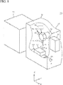
- a cleaning apparatus 10 includes an X-ray CT scanner 11 (hereinafter referred to as "scanner"), a cleaning machine 12, and a control device 31.
- the cleaning machine 12 includes a cleaning chamber 19, a pump 18, and a nozzle 15.
- the cleaning machine 12 may include a turret 13 and a moving device 14.
- the nozzle 15 is, for example, a straight jet nozzle 151 or an L-type nozzle 153.
- the cleaning machine 12 causes a jet 47 from the nozzle 15 to collide with an object 17, and clean or deburr the object 17.
- U.S. Patent Nos. 9,364,869 , 9,393,627 , and 9,630,217 have been proposed as the cleaning machine 12.
- the cleaning machine 12 is sold as the JCC series by Sugino Machine Limited.
- the cleaning table 20 is located in the cleaning chamber 19.
- the cleaning table 20 may be swingable about a rotation axis 21 parallel to the X-axis direction.
- the cleaning table 20 positions and fixes the object 17 at a predetermined position.
- the pump 18 pressurizes the cleaning liquid from a cleaning liquid tank (not shown) and supplies the cleaning liquid to the nozzle 15 via the turret 13.
- the moving device 14 freely moves the turret 13 and the nozzle 15 in the left-right direction (X-axis direction), the front-rear direction (Y-axis direction), and the vertical direction (Z-axis direction) with respect to the cleaning table 20.
- the turret 13 is mounted on the moving device 14.
- the turret 13 has a rotation axis 16 parallel to the Z-axis.
- a plurality of nozzles 15 may be attached to the turret 13.
- the turret 13 turns to index a single nozzle 15 downwardly.
- the turret 13 supplies the cleaning liquid to the downwardly indexed nozzle 15.
- the downwardly indexed nozzle 15 can rotate about a rotation axis 16 or can be positioned in a rotational direction.
- the straight injection nozzle 151 has a shaft body 15a and a nozzle hole 15b.
- the shaft body 15a extends along the rotation axis 16.
- the nozzle hole 15b is disposed at the distal end of the shaft body 15a on the rotation axis 16.
- the nozzle hole 15b generates a jet 47 along the rotation axis 16.
- the L-type nozzle 153 has a shaft body 15a and a nozzle hole 15c.
- the nozzle hole 15c is disposed at the distal end of the shaft body 15a, directing perpendicular to the rotation axis 16.
- the nozzle hole 15c generates a jet 47 in a direction perpendicular to the rotation axis 16.
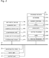
- the control device 31 includes an arithmetic device 32, a storage device 33, an input/output port 34, an input unit 35, an output unit 36, and a bus 37.
- the bus 37 communicably connects the arithmetic device 32, the storage device 33, the input/output port 34, the input unit 35, and the output unit 36.
- the storage device 33 may include a main storage device or an external storage device.
- the storage device 33 stores the 3D model 33b, the scan data 33e, and the entire program 33f.
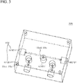
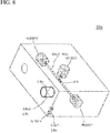
- the 3D model 33b includes a plurality of target portions 33c.
- the same number of labels 33d as the number of partial programs 33h for cleaning each target portion 33c are affixed to the target portion 33c.
- a single label N1001 is affixed to the target portion 33c1.
- Three labels N1201, N3001, N3101 are affixed to the target portion 33c2.
- the entire program includes a label 33d and a partial program 33h associated with the label 33d.
- the partial program 33h includes, for example, a header portion 33h1, a nozzle selection section 33h2, a cleaning target portion section 33h3, a retraction section 33h4, and a footer portion 33h5.
- Each partial program 33h is provided with a label 33d.
- the nozzle selection section 33h2 may be omitted when the cleaning machine 12 has only one nozzle 15.
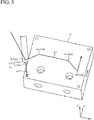
- the trajectory 41 indicates a trajectory of the nozzle 151.
- M06 Nozzle selection.
- M50 Start injection
- M51 Stop injection
- M30 End of block
- T1 Select Straight injection nozzle
- T3 Select L-type nozzle
- the header portion 33h1 includes instructions for substitution of a numerical value into a function parameter or a coordinate system, initial setting of a G code, or, a preparation operation such as closing of a door, clamping, and operation of a pump.
- the nozzle selection section 33h2 includes preparation operations such as retraction for rotating the turret 13, nozzle selection, and starting injection.
- the nozzle selection section 33h2 belongs to an upper layer.
- the cleaning target portion section 33h3 indicates a path of the nozzle for each target portion. For example, in the case of a hole, the path to the opening of the hole is described for each nozzle.
- the cleaning target portion section 33h3 belongs to a lower layer.
- the retraction section 33h4 indicates a path along which the nozzle 15 is retracted.
- the retraction section 33h4 is inserted between the several cleaning target portion sections 33h3.
- the retraction section 33h4 is inserted therebetween so that the nozzle 15 does not interfere with the object 17 or the cleaning machine 12.
- the retraction section 33h4 is, for example, a gate motion or a table rotation operation.
- the retraction section 33h4 belongs to the middle layer.
- FIG. 6 shows an exemplary trajectory (gate-motion) 42 of the retraction section 33h4 to which label N3100 is affixed.
- the L-type nozzle 153 causes the jet 47 to collide with the target portion 33c2 from the opening on the X- side. At this time, the L-type nozzle 153 is located on the X- side of the object 17.
- the trajectory 42 shows that the L-type nozzle 153 moves upward in the Z direction, and then moves to the X+ side of the object 17 on the X-Y plane. Thereafter, the L-type nozzle 153 is moved so that the jet 47 is ejected from the X+ side. At this time, the L-type nozzle 153 moves upward in the Z direction, and thus does not interfere with the object 17.
- the footer portion 33h5 includes instructions of a stop operation such as an origin return operation, door opening, unclamping, pump stopping, and the like.
- the label 33d is numbered with the associated nozzle number (T code) as a thousands place digit, the associated retraction part arrangement order as a hundreds place digit, and the pair of cleaning target portion section 33h3 associated with the nozzle selection part 33h2 or the retraction section 33h4 as the last two digits.
- the processing order of the programs is determined in ascending order of labels.
- the input/output port 34 is connected to the moving device 14 and the pump 18.
- the input unit 35 is, for example, a keyboard or a pointing device.
- the input unit 35 may be a software keyboard or touch panel.
- the output unit 36 is, for example, a monitor.
- the arithmetic device 32 includes a scanning unit 32a, a numerical control unit 32b, a comparison unit 32c, a cleaning portion specifying unit 32d, and a program creating unit 32e.
- a scanning unit 32a controls the scanner 11.
- the numerical control unit 32b numerically controls the moving device 14.
- the numerical control unit 32b controls the pump 18 and the turret 13 in accordance with the cleaning program.
- the comparison unit 32c compares the scan data 33e with the 3D model 33b, and extracts the foreign matter 33i included in the scan data 33e.
- step S1 the scanner 11 scans the object 17 by transmitting a particle beam through the object 17.
- the scanning unit 32a obtains scan data 33e including the structure of the object 17.
- the comparison unit 32c compares the scan data 33e with the 3D model 33b to extract foreign matter from the scan data 33e.
- the comparison unit 32c defines the specific structures inside the target portion 33c1 and the target portion 33c2 as the foreign matter 33i.
- the comparison unit 32c defines a machining error (excessive diameter) 33k with respect to the target portion 33c3.
- step S3 the cleaning portion specifying unit 32d specifies the target portions 33c1 and 33c2 including the extracted foreign matter 33i as cleaning portions. Then, the cleaning portion specifying unit 32d sends the labels N1001, N1201, N3001, N3101 associated with the cleaning points to the program creating unit 32e.
- step S4 the program creating unit 32e creates a cleaning program 33m based on the entire program 33f and the specified cleaning portion.
- the partial program 33h related to the cleaning place is indicated by labels as follows.
- the nozzle selection section 33h2 to which the label N1000 is affixed is associated with the upper layer of the cleaning target portion section 33h3 to which the label N1001 is affixed.
- the retraction portion 33h4 to which the label N3100 is affixed is associated with an upper layer of the cleaning target portion section 33h3 to which the label N3101 is affixed.
- the nozzle selection section 33h2 to which the label N3000 is affixed is associated with the upper layer of the labels N3001 and N3100.
- the program creating unit 32e adds the header portion 33h1 (label: N0010) and the footer portion 33h5 (label: N7000) to the above-described partial program 33h to form the cleaning program 33m.
- the program creating unit 32e arranges the partial programs 33h in the describing order of the entire program 33f, that is, in ascending order of labels, to form the cleaning program 33m.
- step S5 the cleaning machine 12 executes the cleaning program 33m to clean the object 17.
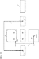
- FIG. 10 shows the trajectories 42 to 43 of the nozzles 151, 153 on an orthogonal view of the object 17 according to the third angle projection.
- the nozzles 151 and 153 clean only the target portions 33c1 and 33c2.
Landscapes
- Engineering & Computer Science (AREA)
- Mechanical Engineering (AREA)
- Chemical & Material Sciences (AREA)
- Chemical Kinetics & Catalysis (AREA)
- General Chemical & Material Sciences (AREA)
- Cleaning By Liquid Or Steam (AREA)
- Numerical Control (AREA)
Applications Claiming Priority (1)
| Application Number | Priority Date | Filing Date | Title |
|---|---|---|---|
| US201962834607P | 2019-04-16 | 2019-04-16 |
Publications (2)
| Publication Number | Publication Date |
|---|---|
| EP3725427A1 true EP3725427A1 (de) | 2020-10-21 |
| EP3725427B1 EP3725427B1 (de) | 2025-11-19 |
Family
ID=69167563
Family Applications (1)
| Application Number | Title | Priority Date | Filing Date |
|---|---|---|---|
| EP19220013.7A Active EP3725427B1 (de) | 2019-04-16 | 2019-12-30 | Reinigungsverfahren und reinigungsmaschine |
Country Status (4)
| Country | Link |
|---|---|
| US (1) | US20200331039A1 (de) |
| EP (1) | EP3725427B1 (de) |
| JP (1) | JP6806875B2 (de) |
| CN (1) | CN111822416B (de) |
Cited By (1)
| Publication number | Priority date | Publication date | Assignee | Title |
|---|---|---|---|---|
| EP4094852A1 (de) * | 2021-05-28 | 2022-11-30 | OHB System AG | Verfahren zur reinigung und reinheitskontrolle |
Families Citing this family (1)
| Publication number | Priority date | Publication date | Assignee | Title |
|---|---|---|---|---|
| WO2024089846A1 (ja) * | 2022-10-27 | 2024-05-02 | ファナック株式会社 | シミュレーション装置及びプログラム |
Citations (12)
| Publication number | Priority date | Publication date | Assignee | Title |
|---|---|---|---|---|
| JPS6147623B2 (de) | 1979-09-21 | 1986-10-20 | Concast Ag | |
| WO2015127547A1 (en) * | 2014-02-27 | 2015-09-03 | Walter Surface Technologies Inc. | Industrial cleanliness measurement methodology |
| US9364869B2 (en) | 2010-09-10 | 2016-06-14 | Sugino Machine Limited | Turret-type cleaning apparatus |
| US9393627B2 (en) | 2013-09-17 | 2016-07-19 | Sugino Machine Limited | Turret device |
| JP2016212661A (ja) * | 2015-05-11 | 2016-12-15 | 株式会社スギノマシン | 噴流衝突領域確認方法、噴流衝突領域確認装置、プログラム、およびコンピュータ読み取り可能な記録媒体 |
| JP2017013182A (ja) * | 2015-07-01 | 2017-01-19 | 富士機械製造株式会社 | 工作機械、ワーク清掃方法 |
| CN106513380A (zh) * | 2016-10-27 | 2017-03-22 | 苏州菲镭泰克激光技术有限公司 | 多孔网状结构物体的激光清洗装置及方法 |
| JP2017062657A (ja) * | 2015-09-25 | 2017-03-30 | 株式会社スギノマシン | 運動プログラムの作成方法、コンピュータ、プログラム、および記録媒体 |
| US9630217B2 (en) | 2014-07-24 | 2017-04-25 | Sugino Machine Limited | Cleaning apparatus |
| JP6338333B2 (ja) * | 2013-07-25 | 2018-06-06 | 中村留精密工業株式会社 | 工作機械の機内洗浄装置 |
| EP3372318A1 (de) * | 2017-03-06 | 2018-09-12 | General Electric Company | Engspaltverarbeitung |
| US20180354000A1 (en) * | 2015-08-11 | 2018-12-13 | Fanuc Corporation | Washing system of machine tool |
Family Cites Families (3)
| Publication number | Priority date | Publication date | Assignee | Title |
|---|---|---|---|---|
| JPH06297292A (ja) * | 1993-04-07 | 1994-10-25 | Mitsubishi Heavy Ind Ltd | 切り粉自動除去装置 |
| JP2001264047A (ja) * | 2000-03-17 | 2001-09-26 | Hitachi Ltd | 立体物造形作業の処理方法 |
| CN104607400B (zh) * | 2015-01-05 | 2017-01-25 | 北京天诚同创电气有限公司 | 光伏电池板的清洁扫描装置及清洁方法 |
-
2019
- 2019-12-19 US US16/720,326 patent/US20200331039A1/en not_active Abandoned
- 2019-12-19 JP JP2019229053A patent/JP6806875B2/ja active Active
- 2019-12-30 EP EP19220013.7A patent/EP3725427B1/de active Active
-
2020
- 2020-01-16 CN CN202010048817.1A patent/CN111822416B/zh active Active
Patent Citations (12)
| Publication number | Priority date | Publication date | Assignee | Title |
|---|---|---|---|---|
| JPS6147623B2 (de) | 1979-09-21 | 1986-10-20 | Concast Ag | |
| US9364869B2 (en) | 2010-09-10 | 2016-06-14 | Sugino Machine Limited | Turret-type cleaning apparatus |
| JP6338333B2 (ja) * | 2013-07-25 | 2018-06-06 | 中村留精密工業株式会社 | 工作機械の機内洗浄装置 |
| US9393627B2 (en) | 2013-09-17 | 2016-07-19 | Sugino Machine Limited | Turret device |
| WO2015127547A1 (en) * | 2014-02-27 | 2015-09-03 | Walter Surface Technologies Inc. | Industrial cleanliness measurement methodology |
| US9630217B2 (en) | 2014-07-24 | 2017-04-25 | Sugino Machine Limited | Cleaning apparatus |
| JP2016212661A (ja) * | 2015-05-11 | 2016-12-15 | 株式会社スギノマシン | 噴流衝突領域確認方法、噴流衝突領域確認装置、プログラム、およびコンピュータ読み取り可能な記録媒体 |
| JP2017013182A (ja) * | 2015-07-01 | 2017-01-19 | 富士機械製造株式会社 | 工作機械、ワーク清掃方法 |
| US20180354000A1 (en) * | 2015-08-11 | 2018-12-13 | Fanuc Corporation | Washing system of machine tool |
| JP2017062657A (ja) * | 2015-09-25 | 2017-03-30 | 株式会社スギノマシン | 運動プログラムの作成方法、コンピュータ、プログラム、および記録媒体 |
| CN106513380A (zh) * | 2016-10-27 | 2017-03-22 | 苏州菲镭泰克激光技术有限公司 | 多孔网状结构物体的激光清洗装置及方法 |
| EP3372318A1 (de) * | 2017-03-06 | 2018-09-12 | General Electric Company | Engspaltverarbeitung |
Cited By (1)
| Publication number | Priority date | Publication date | Assignee | Title |
|---|---|---|---|---|
| EP4094852A1 (de) * | 2021-05-28 | 2022-11-30 | OHB System AG | Verfahren zur reinigung und reinheitskontrolle |
Also Published As
| Publication number | Publication date |
|---|---|
| CN111822416B (zh) | 2021-05-14 |
| JP2020177642A (ja) | 2020-10-29 |
| JP6806875B2 (ja) | 2021-01-06 |
| US20200331039A1 (en) | 2020-10-22 |
| EP3725427B1 (de) | 2025-11-19 |
| CN111822416A (zh) | 2020-10-27 |
Similar Documents
| Publication | Publication Date | Title |
|---|---|---|
| EP3725427B1 (de) | Reinigungsverfahren und reinigungsmaschine | |
| US10668563B2 (en) | Laser machining apparatus | |
| Pham et al. | Part orientation in stereolithography | |
| EP4116033B1 (de) | Werkzeugmaschine, werkzeugmaschinensteuerungsverfahren und werkzeugmaschinensteuerungsprogramm | |
| DE102007063200B4 (de) | Verfahren zum Feinbearbeiten mindestens eines Werkstücks mit Hilfe eines Rotationswerkzeugs und eine Feinbearbeitungsvorrichtung | |
| JP2018008252A (ja) | めねじの洗浄方法 | |
| JP2011095879A (ja) | 研削加工ワークの補正研削加工方法 | |
| EP3878567B1 (de) | Reinigungsverfahren für werkstücke | |
| JP6868157B2 (ja) | 工作機械 | |
| JP2020097036A (ja) | 洗浄機 | |
| US20220008960A1 (en) | Cleaning method and cleaning apparatus | |
| EP3928169A1 (de) | Verfahren und vorrichtung zur taktbasierten programmierung eines steuerprogramms für eine numerisch gesteuerte werkzeugmaschine | |
| JP2001062666A (ja) | 加工及び洗浄の複合装置 | |
| JP7471851B2 (ja) | 工作機械、制御方法、及び、プログラム | |
| US20240269790A1 (en) | Machine tool | |
| EP3805524A2 (de) | Markierung und identifizierung eines verbundmaterials | |
| CN208713538U (zh) | 用于高精密笔记本后盖的cnc加工装置 | |
| CN114167811B (zh) | 一种ug后置处理线性优化方法 | |
| JP7000618B1 (ja) | 工作機械 | |
| KR100764487B1 (ko) | 공작기계용 스핀들 유닛 | |
| EP4468100A2 (de) | System und verfahren zur herstellung eines teils | |
| JP2023125957A (ja) | 切削加工システム、切削加工方法、プログラム及び制御システム | |
| JPH06210544A (ja) | Ncデータ作成装置 | |
| JP2022068587A (ja) | 検出方法 | |
| Zhang et al. | Adaptive measurement enhancing the performance of a five-axis laser robot machine |
Legal Events
| Date | Code | Title | Description |
|---|---|---|---|
| PUAI | Public reference made under article 153(3) epc to a published international application that has entered the european phase |
Free format text: ORIGINAL CODE: 0009012 |
|
| STAA | Information on the status of an ep patent application or granted ep patent |
Free format text: STATUS: REQUEST FOR EXAMINATION WAS MADE |
|
| 17P | Request for examination filed |
Effective date: 20191230 |
|
| AK | Designated contracting states |
Kind code of ref document: A1 Designated state(s): AL AT BE BG CH CY CZ DE DK EE ES FI FR GB GR HR HU IE IS IT LI LT LU LV MC MK MT NL NO PL PT RO RS SE SI SK SM TR |
|
| AX | Request for extension of the european patent |
Extension state: BA ME |
|
| STAA | Information on the status of an ep patent application or granted ep patent |
Free format text: STATUS: EXAMINATION IS IN PROGRESS |
|
| 17Q | First examination report despatched |
Effective date: 20221116 |
|
| RAP3 | Party data changed (applicant data changed or rights of an application transferred) |
Owner name: SUGINO MACHINE LIMITED |
|
| GRAP | Despatch of communication of intention to grant a patent |
Free format text: ORIGINAL CODE: EPIDOSNIGR1 |
|
| STAA | Information on the status of an ep patent application or granted ep patent |
Free format text: STATUS: GRANT OF PATENT IS INTENDED |
|
| GRAS | Grant fee paid |
Free format text: ORIGINAL CODE: EPIDOSNIGR3 |
|
| GRAA | (expected) grant |
Free format text: ORIGINAL CODE: 0009210 |
|
| STAA | Information on the status of an ep patent application or granted ep patent |
Free format text: STATUS: THE PATENT HAS BEEN GRANTED |
|
| INTG | Intention to grant announced |
Effective date: 20250918 |
|
| AK | Designated contracting states |
Kind code of ref document: B1 Designated state(s): AL AT BE BG CH CY CZ DE DK EE ES FI FR GB GR HR HU IE IS IT LI LT LU LV MC MK MT NL NO PL PT RO RS SE SI SK SM TR |
|
| REG | Reference to a national code |
Ref country code: CH Ref legal event code: F10 Free format text: ST27 STATUS EVENT CODE: U-0-0-F10-F00 (AS PROVIDED BY THE NATIONAL OFFICE) Effective date: 20251119 Ref country code: GB Ref legal event code: FG4D |
|
| REG | Reference to a national code |
Ref country code: DE Ref legal event code: R096 Ref document number: 602019078214 Country of ref document: DE |
|
| REG | Reference to a national code |
Ref country code: IE Ref legal event code: FG4D |
|
| PGFP | Annual fee paid to national office [announced via postgrant information from national office to epo] |
Ref country code: DE Payment date: 20251211 Year of fee payment: 7 |
|
| REG | Reference to a national code |
Ref country code: NL Ref legal event code: MP Effective date: 20251119 |
|
| PG25 | Lapsed in a contracting state [announced via postgrant information from national office to epo] |
Ref country code: ES Free format text: LAPSE BECAUSE OF FAILURE TO SUBMIT A TRANSLATION OF THE DESCRIPTION OR TO PAY THE FEE WITHIN THE PRESCRIBED TIME-LIMIT Effective date: 20251119 |
|
| REG | Reference to a national code |
Ref country code: LT Ref legal event code: MG9D |
|
| PG25 | Lapsed in a contracting state [announced via postgrant information from national office to epo] |
Ref country code: NO Free format text: LAPSE BECAUSE OF FAILURE TO SUBMIT A TRANSLATION OF THE DESCRIPTION OR TO PAY THE FEE WITHIN THE PRESCRIBED TIME-LIMIT Effective date: 20260219 |
|
| PG25 | Lapsed in a contracting state [announced via postgrant information from national office to epo] |
Ref country code: FI Free format text: LAPSE BECAUSE OF FAILURE TO SUBMIT A TRANSLATION OF THE DESCRIPTION OR TO PAY THE FEE WITHIN THE PRESCRIBED TIME-LIMIT Effective date: 20251119 Ref country code: AT Free format text: LAPSE BECAUSE OF FAILURE TO SUBMIT A TRANSLATION OF THE DESCRIPTION OR TO PAY THE FEE WITHIN THE PRESCRIBED TIME-LIMIT Effective date: 20251119 Ref country code: HR Free format text: LAPSE BECAUSE OF FAILURE TO SUBMIT A TRANSLATION OF THE DESCRIPTION OR TO PAY THE FEE WITHIN THE PRESCRIBED TIME-LIMIT Effective date: 20251119 |
|
| PGFP | Annual fee paid to national office [announced via postgrant information from national office to epo] |
Ref country code: IT Payment date: 20260227 Year of fee payment: 7 |
|
| REG | Reference to a national code |
Ref country code: AT Ref legal event code: MK05 Ref document number: 1858422 Country of ref document: AT Kind code of ref document: T Effective date: 20251119 |
|
| PG25 | Lapsed in a contracting state [announced via postgrant information from national office to epo] |
Ref country code: NL Free format text: LAPSE BECAUSE OF FAILURE TO SUBMIT A TRANSLATION OF THE DESCRIPTION OR TO PAY THE FEE WITHIN THE PRESCRIBED TIME-LIMIT Effective date: 20251119 |
|
| PG25 | Lapsed in a contracting state [announced via postgrant information from national office to epo] |
Ref country code: RS Free format text: LAPSE BECAUSE OF FAILURE TO SUBMIT A TRANSLATION OF THE DESCRIPTION OR TO PAY THE FEE WITHIN THE PRESCRIBED TIME-LIMIT Effective date: 20260219 |
|
| PG25 | Lapsed in a contracting state [announced via postgrant information from national office to epo] |
Ref country code: IS Free format text: LAPSE BECAUSE OF FAILURE TO SUBMIT A TRANSLATION OF THE DESCRIPTION OR TO PAY THE FEE WITHIN THE PRESCRIBED TIME-LIMIT Effective date: 20260319 |
|
| PGFP | Annual fee paid to national office [announced via postgrant information from national office to epo] |
Ref country code: FR Payment date: 20260113 Year of fee payment: 7 |
|
| PG25 | Lapsed in a contracting state [announced via postgrant information from national office to epo] |
Ref country code: PT Free format text: LAPSE BECAUSE OF FAILURE TO SUBMIT A TRANSLATION OF THE DESCRIPTION OR TO PAY THE FEE WITHIN THE PRESCRIBED TIME-LIMIT Effective date: 20260319 |
|
| PG25 | Lapsed in a contracting state [announced via postgrant information from national office to epo] |
Ref country code: PL Free format text: LAPSE BECAUSE OF FAILURE TO SUBMIT A TRANSLATION OF THE DESCRIPTION OR TO PAY THE FEE WITHIN THE PRESCRIBED TIME-LIMIT Effective date: 20251119 |
|
| PG25 | Lapsed in a contracting state [announced via postgrant information from national office to epo] |
Ref country code: LV Free format text: LAPSE BECAUSE OF FAILURE TO SUBMIT A TRANSLATION OF THE DESCRIPTION OR TO PAY THE FEE WITHIN THE PRESCRIBED TIME-LIMIT Effective date: 20251119 |